

Page 1

User Manual X8400 sc 1
X8400sc
User Manual
Document Number: DC085U
Version: C
Issue Date: 08/03/2013
Page 2

User Manual X8400 sc 2
Table of Contents
1 REVISION HISTORY ................................................................................................................................................. 4
2 INTRODUCTION ..................................................................................................................................................... 5
2.1 C
AMERA SYSTEM COMPONENTS
................................................................................................................................... 5
2.2 S
YSTEM OVERVIEW
.................................................................................................................................................... 6
2.3 K
EY FEATURES OF THE
X8400
SC CAMERA
....................................................................................................................... 8
3 WARNINGS AND CAUTIONS ................................................................................................................................. 10
4 INSTALLING THE X8400SC ON THE EXPERIMENT .................................................................................................. 11
4.1 M
OUNTING THE CAMERA
.......................................................................................................................................... 11
4.2 P
OWERING THE CAMERA
........................................................................................................................................... 11
4.2.1 Power supply 11
4.2.2 Power button 11
4.2.3 Camera boot-up and Cooling down 12
4.3 A
DJUSTING FIELD OF VIEW
......................................................................................................................................... 12
4.3.1 LCD Screen 12
4.3.2 Lens 14
4.4 S
ETTING THE CAMERA PARAMETERS
............................................................................................................................ 16
4.4.1 Connection to Computer 16
4.4.2 Connection to FLIR ResearchIR Max 16
4.4.3 Image size adjustment 17
4.4.4 Measurement configuration 18
4.4.5 Temperature Range adjustment 19
4.4.6 Frame frequency 20
4.4.7 Synchronizing the camera to an external signal 20
4.4.8 Advanced camera controls 21
4.4.9 Extended Camera Information 22
5 X8400SC OPERATIONS ......................................................................................................................................... 23
5.1 F
ILTER WHEEL
........................................................................................................................................................ 23
5.1.1 Removing an optical filter holder 23
5.1.2 Installing an optical filter holder 23
5.1.3 Filter holder identification 24
5.1.4 Creating custom filter holder 24
5.1.5 Adding a custom filter parameter into the camera 25
5.1.6 Filter definition file description 26
5.2 C
AMERA CONFIGURATION FILE MANAGEMENT
............................................................................................................... 27
5.2.1 CNUC file management 27
5.3 C
AMERA WI-FI APPLICATION
..................................................................................................................................... 27
5.4 I
NFRARED REMOTE
.................................................................................................................................................. 28
6 RADIOMETRIC MEASUREMENT WITH THE X8400SC ............................................................................................. 29
6.1 N
ON UNIFORMITY CORRECTION
................................................................................................................................. 29
6.1.1 CNUC™ 29
6.1.2 Two-Point Correction Process 29
6.1.3 One point Correction (offset correction) 30
6.2 T
EMPERATURE CALIBRATION
...................................................................................................................................... 30
6.2.1 Hypercal™ 30
6.2.2 AutoExposure 30
6.3 30
6.4 B
AD PIXEL REPLACEMENT
.......................................................................................................................................... 31
6.5 F
RAME RATE AND INTEGRATION MODES
...................................................................................................................... 31
6.5.1 Integrate Then Read 31
6.5.2 Integrate While Read 34
6.5.3 Selecting detector integration mode 35
6.6 D
YNAMIC RANGE EXTENSION “SUPERFRAMING
” ........................................................................................................... 36
6.7 C
AMERA SYNCHRONIZATION
...................................................................................................................................... 36
6.7.1 Sync In 37
6.7.2 Sync Out 38
6.8 T
RIGGER
IN ............................................................................................................................................................ 39
6.9 L
OCKIN
.................................................................................................................................................................. 40
7 INTERFACES ......................................................................................................................................................... 41
7.1 WI-F
I CONNECTION
................................................................................................................................................. 41
7.2 USB
CONNECTION
................................................................................................................................................... 43
7.2.1 USB Driver Installation 43
Page 3

User Manual X8400 sc 3
7.2.2
Accessing the camera files with Windows Explorer 47
7.3 M
ECHANICAL
.......................................................................................................................................................... 48
8 SPECIFICATIONS ................................................................................................................................................... 50
8.1 D
IMENSIONS
.......................................................................................................................................................... 50
8.2 I
NTERFACES
............................................................................................................................................................ 50
8.3 W
INDOWING CAPACITY
............................................................................................................................................ 50
8.4 P
OWER
.................................................................................................................................................................. 50
8.5 P
ERFORMANCE CHARACTERISTICS
............................................................................................................................... 51
8.6 D
ETECTOR
/FPA ...................................................................................................................................................... 51
8.7 C
AMERA LINK
......................................................................................................................................................... 51
8.8 E
XTENSION CONNECTOR
............................................................................................................................................ 51
9 MAINTENANCE AND SERVICE ............................................................................................................................... 52
9.1 C
AMERA AND LENS CLEANING
.................................................................................................................................... 52
9.1.1 Camera Body, Cables and Accessories 52
9.1.2 Lens 52
9.2 C
OOLER
................................................................................................................................................................. 52
9.3 FLIR C
USTOMER SUPPORT
........................................................................................................................................ 53
9.3.1 Technical Support 53
9.3.2 FLIR Knowledgebase (FAQ) 53
9.3.3 Repair Services 53
10 QUALITY............................................................................................................................................................... 54
10.1 F
OR US MARKET
..................................................................................................................................................... 54
10.2 F
OR CANADIAN MARKET
........................................................................................................................................... 54
10.3 F
OR THE WHOLE WORLD
........................................................................................................................................... 54
11 LEGAL DISCLAIMER .............................................................................................................................................. 55
12 COPYRIGHTS ........................................................................................................................................................ 56
Page 4

User Manual X8400 sc 4
1 REVISION HISTORY
Version
Date
Author
Changes
A 14/05/2012 E.VANNEAU Creation
B 19/12/2012 E.VANNEAU Modification for new version
C 19/02/2013 E.VANNEAU Modification for V2013
Page 5

User Manual X8400 sc 5
2 INTRODUCTION
2.1 Camera System Components
The X8400sc infrared camera and its accessories are delivered in a transport case which
typically contains the items below.
• X8400sc camera with removable LCD touchscreen.
• Portfolio containing important information on the camera
o Packing list
o Factory acceptance report
o Calibration curves (if applicable)
o Camera files on a CD-ROM
o Optical cleaning tissue
o Filter holding tool
o Micro SD card with SD adapter
• Camera Power supply
• Camera cables
o Power Supply
o Ethernet GigE with locks
o 50 Ohms Coaxial cable for sync (Yellow colored)
o 50 Ohms Coaxial cable for triggering (Orange colored)
o 50 Ohms Coaxial cable for lockin (Green colored)
o 75 Ohms Coaxial cable for general purposes (Blue colored)
o LCD extender cable (with right angle USB connectors)
• LCD connector protective cap
There may also be additional items that you have ordered such as software or CDs.
Page 6
User Manual X8400 sc 6
2.2 System Overview
The X8400sc infrared camera system has been developed by FLIR to meet the needs of the
research communities. The camera makes use of an advanced 1280x1024 digital readout
circuit (ROIC), mated to an Indium Antimonide (InSb) detector to cover the 1.5-5.5µm
Midwave infrared band.
The X8400sc is a stand-alone imaging camera that interfaces to host PCs using standard
interfaces, including Gigabit Ethernet and Cameral Link® medium.
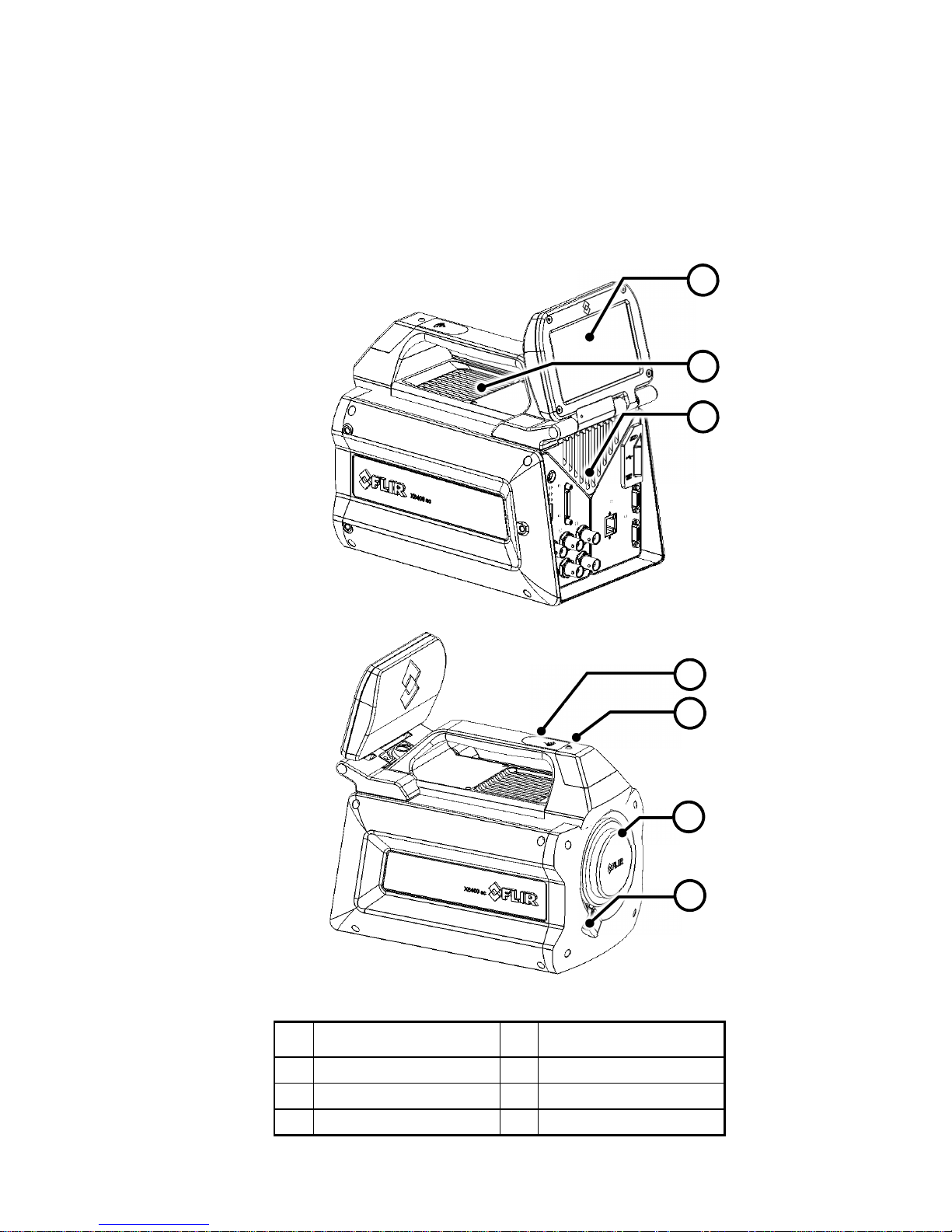
Figure 1: Camera general description
1
Removable touchscreen
LCD
5 Global Status LED
2 External cooling intake 6 Lens Bayonet Interface
3 External cooling exhaust 7 Lens release latch
4 Wi-Fi antenna
1
2
3
4
5
6
7
Page 7
User Manual X8400 sc 7
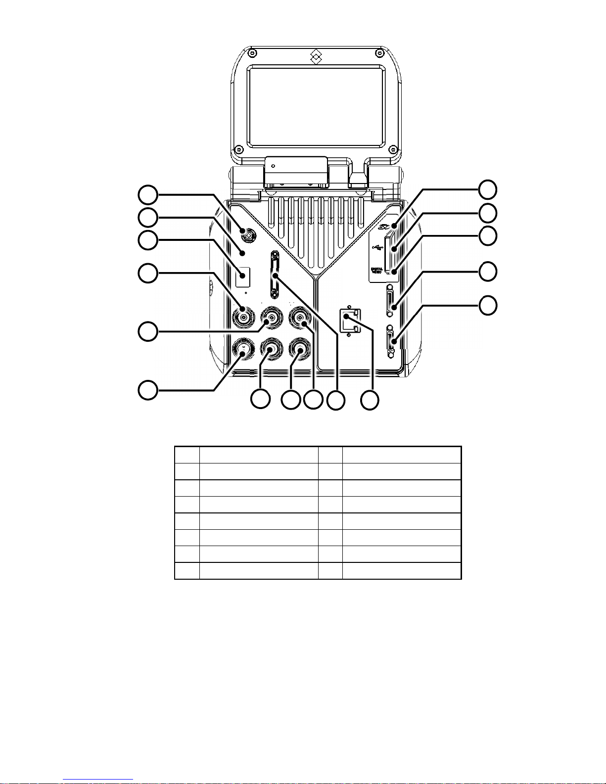
Figure 2: Camera back panel description
1 Power Button 9 Trigger IN
2 Status LED 10 Auxilliary Port
3 IR Remote Sensor 11 GigEVision
4 Sync IN 12 Camera Link Base
5 Sync OUT 13 Camera Link Medium
6 Power IN 14 Digital Video Interface
7 Lockin IN 15 USB
8 General Purpose IO 16 Micro SD-Card
1
2
3
7
4
6
5
8
9
10
11
12
13
14
15
16
Page 8

User Manual X8400 sc 8
2.3 Key features of the X8400sc camera
• 1.3 million pixels – 1280x1024
The X8400sc provides 1.3 million pixels per image, allowing enlarging the area under
inspection with same instantaneous field of view (IFOV) lenses or increasing the spatial
resolution with the same field of view (FOV). The snapshot integration ensures that all pixels
are temporally coherent.
• Fast Frame Rate
The FLIR X8400sc Series have an adjustable frame rate of up to 106 Hz full frame and more
than 3 kHz at 48x4. Windowing allows a subset of the total image to be selectively read out
with user adjustable window size. The sub-sample windows can be arbitrarily chosen and are
easily defined.
• 14-Bit Digital Image Data
The X8400sc camera detector is digital. The A/D conversion is performed directly into the
ROIC in 14-bit depth. The embedded digitalization improves noise and linearity performances
to an outstanding standard.
• Outstanding measurement accuracy
High accuracy of +/- 1ºC or +/- 1% produces sensitive thermal images. The FLIR X8400sc
can measure temperatures up to +3,000º C. The FLIR X8400sc detects temperature
differences smaller than 25mK (18mK typically).
• CNUC™ Calibration
CNUC™ is a proprietary calibration process that provides beautiful imagery and
measurement stability. CNUC™ allows for flexible integration time adjustments without the
need to perform non-uniformity corrections. CNUC™ calibration also produces accurate
measurement stability regardless of camera exposure to ambient temperature variations.
• Hypercal™
Hypercal™ ensures the best measurement range with the highest sensitivity. Simply set the
desired lower and upper temperature limits and the camera will automatically adjust to the
appropriate integration (exposure) time.
• Auto exposure
The camera automatically adjusts its temperature range to best fit the thermal scene.
• Presets
Up to eight presets and their associated parameters, such as integration time, frame rate,
window size and window location, are available for instant selection with a single command.
These presets can be used in Dynamic Range Extension (DRX) mode (also called
Superframing”) which allows the acquisition of thermal data from up to four user-defined
temperature ranges simultaneously, then merges those streams into a single real-time data
stream that spans all four temperature ranges, effectively extending dynamic range from 14
bit to 16 bit.
• Multiple Triggering Modes and Synchronizing Interfaces
The X8400sc camera provides different interfaces to support maximum flexibility for
synchronizing the camera to external events, as well as synchronizing external events to the
camera.
o Sync In (TTL)
o Sync Out
o Trigger In
• Multiple Video Outputs
The X8400sc camera features multiple independent and simultaneous videos:
o Digital 14-bit video – CameraLink® Base or Medium
o Digital 14-bit video – Gigabit Ethernet – GigEVision Compliant
o Digital 8-bit Video – DVI format 1080p30 digital output
• Wide range of interchangeable lenses
The FLIR X8400sc comes with an advanced high performance optical design with lens
recognition and automatic measurement adjustments. It is also possible to manually adjust
the focus directly on the camera. A temperature probe is integrated in the lens for improved
measurement accuracy and drift compensation.
A wide range of lenses and various extension rings are available.
• Motorized filter wheel
The FLIR X8400sc contains a 4 slot motorized filter wheel with automatic filter recognition
and measurement parameter adjustment. The removable filter holders contain an integrated
temperature probe for improved measurement accuracy.
Page 9

User Manual X8400 sc 9
• Removable Touchscreen LCD
The detachable touchscreen LCD provides you with on-site image feedback and camera
configuration parameters. The camera can easily be adjusted to the needs. One touch on the
screen controls the acquisition on the computer.
The LCD touchscreen can be removed from the camera when the FLIR X8400sc needs to be
installed in a hard to reach position. Just position the camera and control it from a distance.
• Wi-Fi
The camera embeds a Wi-Fi interface which enables to control it via a smart phone (iPhone)
or a tablet PC (iPad).
• Video Color Palettes
The X8400sc camera supports a selection of standard and user-defined color palettes (or
grayscale) for the DVI video.
• Configuration management
Save your camera configuration to the SD-Card when loaning your camera to your colleague.
Once back, just insert your SD-card and get the camera up and running with exactly your
configuration. Stop wasting time to reconfigure your thermal measurement system.
• Global Status LED
Located on the top of the camera, the global status LED provides instant system status,
including ResearchIR Max status. When green, no doubt your experiment will be fully
acquired. The back panel LEDs instantly informs you about the camera status.
Page 10

User Manual X8400 sc 10
3 Warnings and Cautions
For best results and user safety, the following warnings and precautions should be followed
when handling and operating the camera.
Warnings and Cautions:
o Do not open the camera body for any reason. Disassembly of the camera (including
removal of the cover) can cause permanent damage and will void the warranty.
o Great care should be exercised with your camera optics. Refer to Chapter 9.1.2 for lens
cleaning.
o Operating the camera outside of the specified input voltage range or the specified operating
temperature range can cause permanent damage.
o Do not image extremely high intensity radiation sources, such as the sun, lasers, arc
welders, etc.
o The camera is a precision optical instrument and should not be exposed to excessive shock
and/or vibration.
o The camera contains static-sensitive electronics and should be handled appropriately
o Though the camera laser is a class I laser, avoid looking directly at it when activated
o Do not put any item on the external cooling intake (#2 on Figure 1 Camera general
description) to maintain the cooling of the camera
Page 11
User Manual X8400 sc 11
4 INSTALLING THE X8400sc ON THE EXPERIMENT
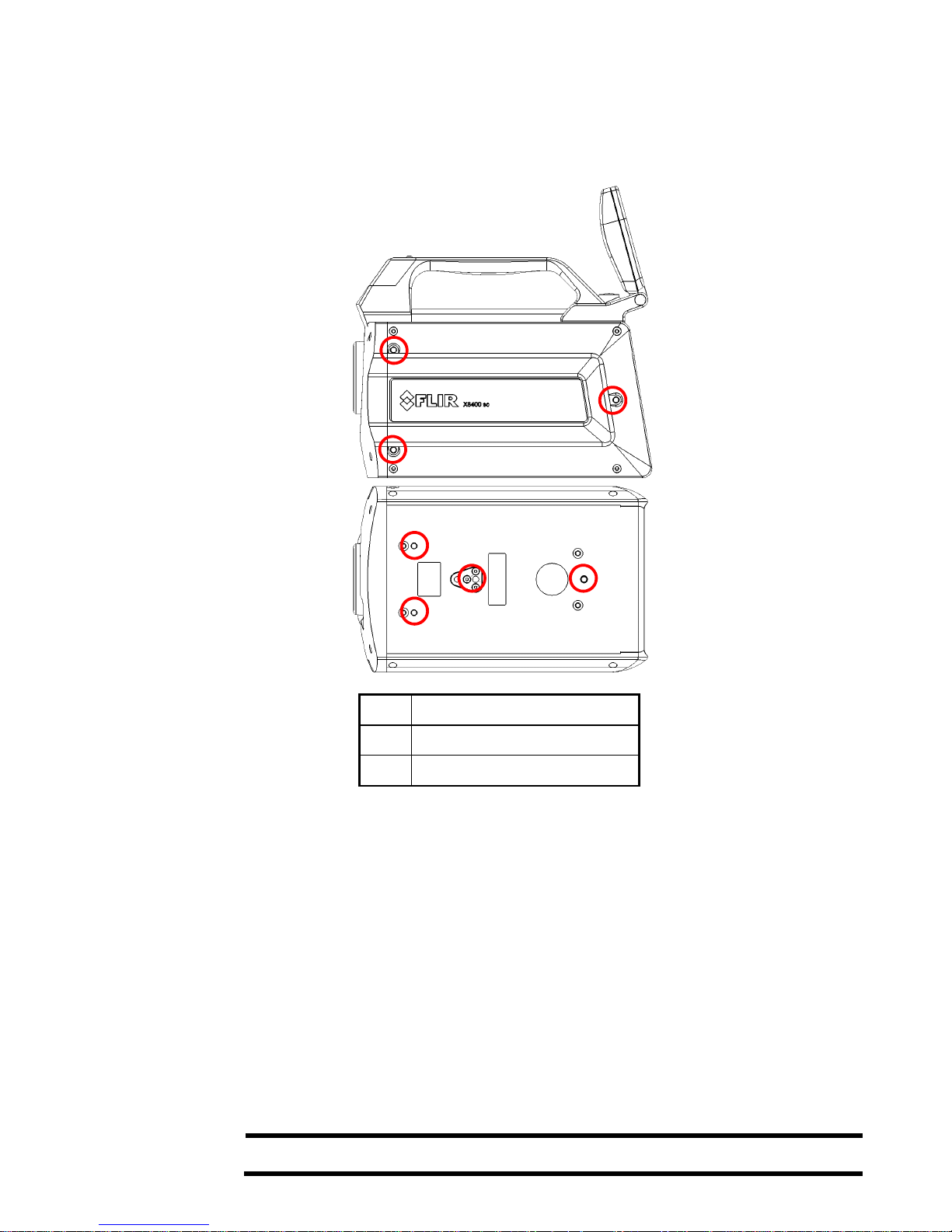
4.1 Mounting the camera
The camera can be operated installed either on a workbench or mounted on a tripod or
custom mount. Standard photo mount interface (1/4” UNC-20 or 3xM5 on camera bottom as
well as 3xM5 on left side of the camera) are available.
1 ¼ UNC – 20
2 Camera base plate M5 threads
3 Camera left side M5 threads
4.2 Powering the camera
4.2.1 Power supply
The camera is powered through the red power connector (#6 on Figure 1: Camera back
panel description) on the back panel. Connect the 24VDC power supply provided with the
camera (PN X1159).
The power button (#1 on Figure 1: Camera back panel description) now blinks slowly,
indicating power is received at the camera level.
Please refer to chapter 9.5 for power supply technical data.
4.2.2 Power button
The power button (#1 on Figure 2: Camera back panel description) is located behind the
touchscreen LCD. Open the touchscreen LCD to its maximal extension to access the button.
Note
Keep the LCD screen opened or detach it when the camera is under operation not to block
the external cooling exhaust
1
2
2
2
Page 12

User Manual X8400 sc 12
Press the power button shortly to start the camera.
When the camera is running,
o A short press on the power button starts the camera shutdown procedure.
The camera is switched off some seconds later.
o A long press on the power button forces the camera to stop immediately,
bypassing the shutdown procedure.
4.2.3 Camera boot-up and Cooling down
When starting up, the embedded Stirling cooler starts first. Stirling coolers produce noise
which is typical to advanced cooled science cameras. A high volume of noise is normal.
The camera requires up to 7 minutes reaching the detector temperature of 77K. In parallel,
the camera performs a built-in test of its components and initializes the internal software and
interfaces.
The camera is ready to use when the all status LEDs on back panel are green (#2 on Figure
2: Camera back panel description).
4.3 Adjusting Field of view
Once the camera is installed and running, the field of view of the camera is adjusted to match
the thermal scene under experiment. This adjustment is done by selecting the best lens for
the field of view to achieve, and then by fine tuning the camera position to the scene.
The LCD described hereby is a useful tool during that process.
4.3.1 LCD Screen
The X8400sc embeds a detachable touchscreen LCD which provides instant thermal image
feedback. The LCD screen also presents camera information, adjustment controls and
ResearchIR Max acquisition control.
In the LCD screenshot example hereby, the camera measurement configuration and
temperature range is adapted to the thermal scene. If the camera is not correctly set up for
the scene, the image displayed can then be either black or white.
Page 13

User Manual X8400 sc 13
The temperature range of the camera can be automatically adjusted using the autoexposure
button on the touchscreen. Please refer to §6.2.2 for more information on autoexposure.
If the thermal scene does not match the configuration measurement (spectral filter on filter
wheel), it is required to select the correct configuration measurement in ResearchIR Max.
Please refer to §4.4.4)
Figure 3 : LCD Touchscreen Description
1 Image Statistics 4
Start Acquisition in
ResearchIR Max
2
Camera configuration
information
5 Auto-exposure
3
Synchronisation
information
6 Change Color palette
Detaching the touchscreen LCD
4.3.1.1
The LCD screen can be detached from the camera and used remotely when the camera is
mounted on hard to reach position.
Note
• The camera can still be operated without any LCD screen connected.
• The screen can be detached and attached while the camera is in operation
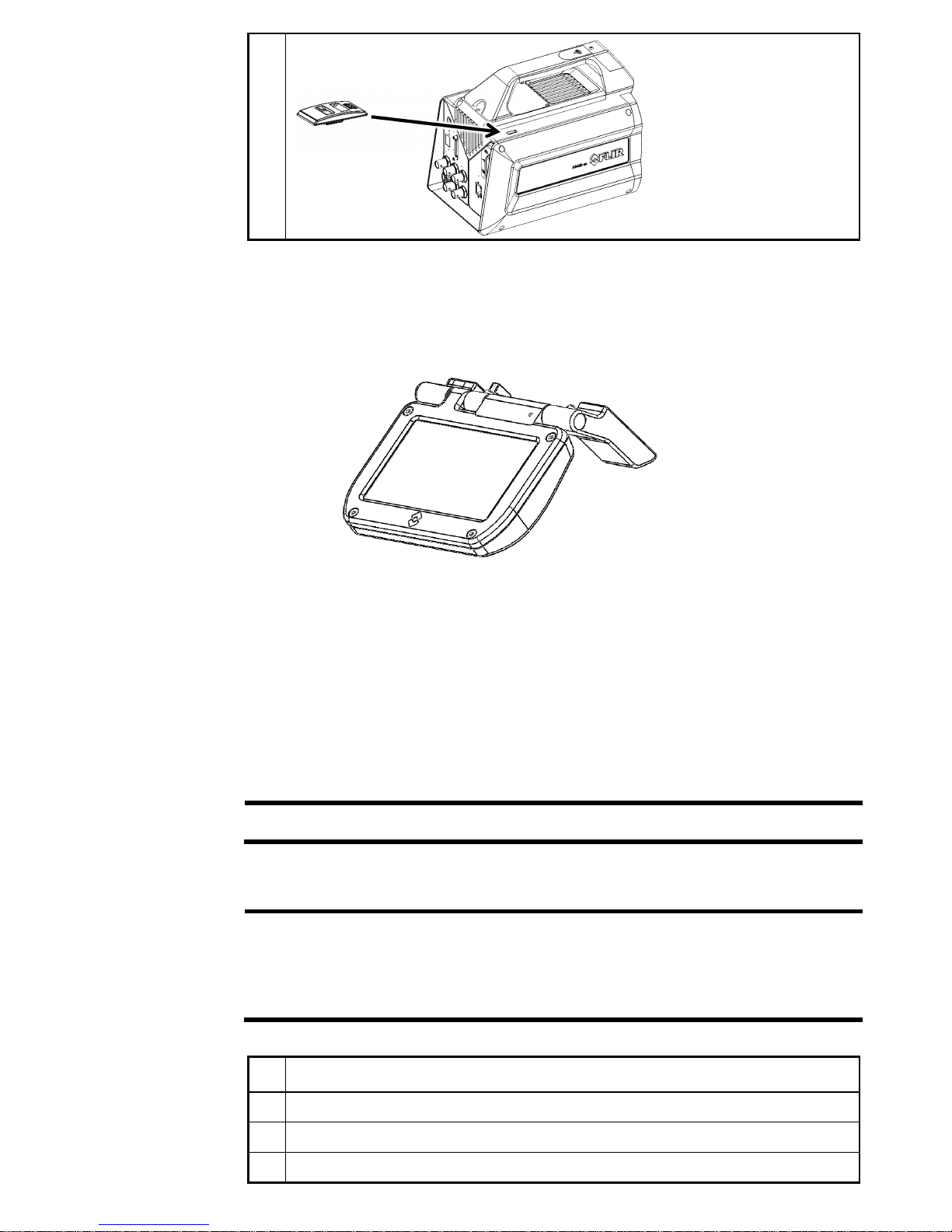
Procedure Follow the procedure to install and detach the LCD screen from the camera
1
Unscrew the LCD screw using a flat screwdriver or a simple coin
2 Gently lift up the screen to disconnect it from the camera
3
Set in place the protective cap provided with the camera to avoid dust or water to
enter in the camera
4
5
2
3
6
1
Page 14
User Manual X8400 sc 14
General When detached, the LCD screen can be connected to the camera using a provided right
angled USB extender cable. Any additional USB extender cable can be added to extend the
length. Performances are then strongly depending on the quality of the used cable and the
environment in which the camera is used.
The screen has been designed to be easily used on a workbench, as shown in next figure
The screen detects automatically its orientation and flips the interface accordingly. The
orientation can be locked in the ResearchIR Max camera user interface (see §4.4.8)
4.3.2 Lens
A large range of lenses is available for the X8400sc. Lenses feature a professional bayonet
mount with lock. Each lens is identified through the bayonet connector. A temperature probe
is also integrated into the lens. This probe is used by the camera to compensate for thermal
drifts.
Note
• FLIR is continuously extending the range of available optics. Contact your FLIR
sales representative for more information on the newly available optics.
Installing an infrared lens
4.3.2.1
Note
• The detector is a very sensitive sensor. It must not be directed towards strong visible
or sun light.
• Do not touch the lens surface when you install the lens. If this happens, clean the
lens accordingly to the instructions in section 9.1.2 on page 52.
• Do not touch the filter surface when you install the lens. If this happens, clean the
filter accordingly to the instructions in section 9.1.2 on page 52
Procedure Follow the procedure to install an infrared lens
1
If any, remove the previous lens or the protection that was in front of the detector/filter
wheel
2 Align the red index mark on the lens with the red index mark on the bayonet ring
3 Carefully push the infrared lens into the bayonet ring
4 Rotate the infrared lens 30° clockwise (looking a t the front of the lens)
Page 15

User Manual X8400 sc 15
Removing an infrared lens
4.3.2.2
Note
• The detector is a very sensitive sensor. It must not be directed towards strong visible
or sun light.
• Do not touch the lens surface when you install the lens. If this happens, clean the
lens accordingly to the instructions in section 9.1.2 on page 52.
• Lenses can be heavy. Some lenses weight several hundred grams. Be careful not to
be surprised by its weight.
• When you have removed the infrared lens, put the lens caps on the lens to protect it
from dust and fingerprints.
Procedure
Follow the procedure to remove an infrared lens
1
Push forward the release button for the infrared lens (#8 on Figure 1: Camera general
description).
2 Rotate the infrared lens 30° counter-clockwise (l ooking at the front of the lens)
3 Carefully pull out the infrared lens from the bayonet ring
4
Install the protective cap or a new optic on the camera to avoid visible light to be
directed to the detector.
Lens identification
4.3.2.3
X8400sc lenses integrate a unique identifier. The camera reads the lens identifier and
automatically adapts the measurement ranges to the connected lens.
The lens connected to the camera is displayed in ResearchIR Max and on the LCD interface.
Adjusting the camera focus
4.3.2.4
Note
• Do not touch the lens surface when you install the lens. If this happens, clean the
lens accordingly to the instructions in section 9.1.2 on page 52.
Camera focus can be done manually by rotating the focus ring on the lens.
Procedure
• For far focus, rotate the focus ring counterclockwise (looking at the front of the
lens)
• For near focus, rotate the focus ring clockwise (looking at the front of the lens)
Using an Extension ring
4.3.2.5
Note
• The detector is a very sensitive sensor. It must not be directed towards strong visible
or sun light.
• Do not touch the lens surface when you install the lens. If this happens, clean the
lens accordingly to the instructions in section 9.1.2 on page 52.
• Using an extension ring requires the user to have strong understanding of the
radiometric consequences and induced measurement errors. Infrared Training
Center (ITC) offers courses and training. For more information about obtaining the
training you require, contact your FLIR sales representative or ITC at
www.infraredtraining.com
Extension rings can be introduced between the camera and the infrared lens in order to
change the minimum focus distance and thus the field of view of the camera. It is possible to
add several extension rings at the same time.
Please refer to the specification sheet of your infrared lens for available extension ring
dimensions and corresponding performances.
When an extension ring is used, the identification of the measurement configuration to be
used by the camera is done manually. Please refer to §4.4.4.
Page 16

User Manual X8400 sc 16
4.4 Setting the camera parameters
4.4.1 Connection to Computer
Connect the camera to the computer. It can be connected either with CameraLink® or GigE.
Although it is possible to use both interfaces in parallel, only one of these should send
commands to the camera. The second PC shall be used only to retrieve images.
Connection through camera link interface
4.4.1.1
CameraLink® is a standard data interface for high end visible and IR cameras. The X8400sc
uses a CameraLink® Medium interface in a single tap, 16-bit configuration. In terms of ports,
the A and B ports are used with bit A0 being the LSB and bit B7 being the MSB of the
transferred data. The header row uses the entire 16-bit value while the pixel data has a 14-bit
range with the upper MSB’s masked to “0”.
In base mode, the camera is connected to the computer using one camera link cable (Refer
to §8.7 for cable reference and CameraLink® information). Connect the cable to connector
#12 on Figure 2: Camera back panel description. The maximum frame frequency is limited in
base mode.
In medium mode, the camera is connected to the computer using two camera link cables
(Refer to §8.7 for cable reference and CameraLink® information). Connect the cables to
connector #12 and #13 on Figure 2: Camera back panel description. This configuration
allows reaching the maximum frame frequency of the camera.
The CameraLink® mode is selected with the ResearchIR Max camera control panel interface.
Please refer to §4.4.8
). It should be always set to BASE for X8400sc cameras.
Note
• Various connector notations can be found on CameraLink® medium frame grabbers
(0&1, 1&2, A&B), make sure to connect the camera connector #12 with the first port
of the frame grabber.
• ResearchIR Max software supports a variety of frame grabbers. Contact your FLIR
sales representative for more information on compatibility.
Connection through Gigabit Ethernet interface
4.4.1.2
The X8400sc camera features a Gigabit Ethernet connection. The GigE interface can be
used for image acquisition and/or camera control. The GigE interface uses a Pleora NTXmini
interface. The GigE interface is GigE Vision compliant.
Gigabit Ethernet is available when the camera is in BASE mode. Please refer to §4.4.8 for
mode selection.
Note
• Use only the high quality Ethernet cable provided with the camera or a CAT 6
equivalent cable.
• The GigE driver installation procedure requires to be thoroughly followed. Please
contact your FLIR local support if required.
4.4.2 Connection to FLIR ResearchIR Max
Note
• Refer to 4.4.1 Connection to Computer to make sure the camera is correctly
connected to the computer.
Page 17
User Manual X8400 sc 17
General The X8400sc camera is interfaced with FLIR ResearchIR Max software. FLIR ResearchIR
Max is a powerful image acquisition and analysis tool. Please refer to ResearchIR Max user
manual for operating instructions. X8400sc specific camera control is described in this
document.
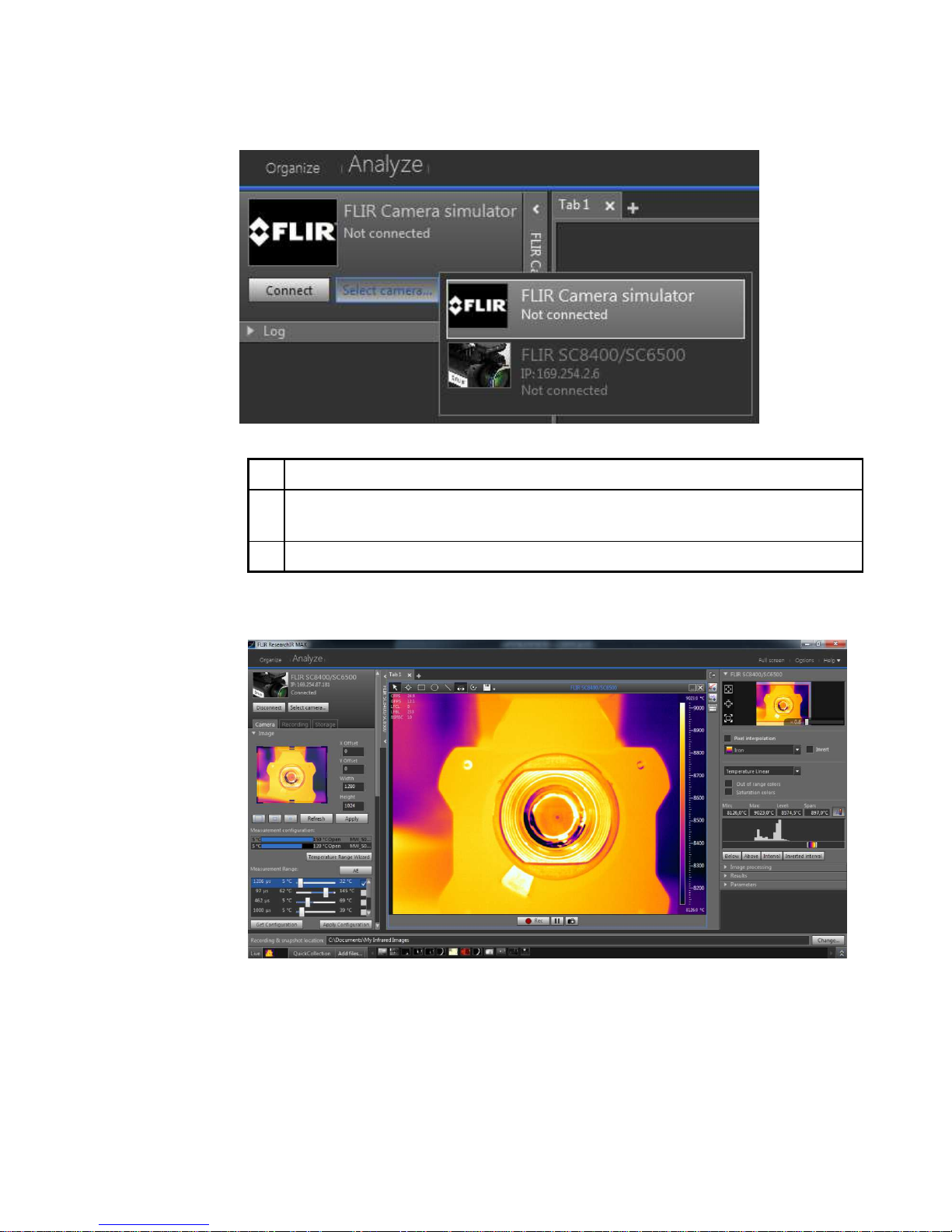
Procedure
Follow the procedure to select and connect the camera
1 Click the select camera button
2
Select the X8400sc camera.
The camera’s IP address is displayed when connected with GigE connection.
The CameraLink® port is displayed when connected with CameraLink®.
3 Click Connect button to activate the camera connection.
Once connected, the camera control interface is populated with camera parameters and the
live image is displayed on the current tab.
4.4.3 Image size adjustment
General The X8400sc camera can be set up to use a subpart of the detector. As a consequence, the
camera can be operated at higher frame rates. The selection is done through the upper part
of the camera control panel.
Page 18

User Manual X8400 sc 18
1
Preview window. The FPA window size can be selected by dragging the handles. The
whole box can be dragged to set the location.
2 X offset can be manually set in this field.
3 Y offset can be manually set in this field.
4 The window width can be manually set in this field
5 The window height can be manually set in this field
6 Set the window size to full detector size (640x512)
7 Set the window size to half detector size (320x256 centered)
8 Set the window size to quarter detector size (160x128 centered)
9 Refresh the preview window with last acquired image from camera.
10 Apply the settings to the camera.
11 Calibrate the image against a homogeneous reference target (also called 1-point NUC)
4.4.4 Measurement configuration
General The measurement configurations available on the camera are displayed on the interface. A
measurement configuration is a combination of optical setup (lenses and spectral filters) and
detector operating modes (ITR/IWR).
Each configuration is described with minimum and maximum calibrated temperatures, filter
and lens configuration. Only the configurations which are relevant to the actual camera setup
are displayed.
The configuration is selected by simply clicking on it. It is then highlighted in light grey. Once
selected, the camera is automatically set to this configuration.
It is possible to deactivate the configuration filter by unchecking the hereby shown check box.
When unchecked, all configurations available on the camera are listed. It is then possible to
select a configuration which does not match with the current optical and detector setup. This
is useful for advanced users when, for instance, using an infrared lens for which no
calibration files are available. In this example, the camera will provide temperature data even
if the calibration does not apply to the lens.
Note
• Only one measurement configuration is valid at one time.
• Make sure to select a configuration which matches the temperature of the scene to
be measured. If not, your measurements will not be correct because outside the
limits of the calibration.
2
3
4
5
1
9
10
11
8
7
6
Page 19

User Manual X8400 sc 19
4.4.5 Temperature Range adjustment
General The temperature range is defined by the minimum and maximum temperatures which can be
measured for a given integration time.
1
Integration time: the given integration time for the range. Double click on the
integration time to manually enter a value. The range is shadowed in red and will be
applied to the camera after clicking on the Apply Configuration button.
2
Drag the range slider to adjust integration time. The corresponding lower and upper
temperatures of the range are displayed. The range is shadowed in red and will be
applied to the camera after clicking on the Apply Configuration button.
3
Activate the range by checking the box. If more than one range is activated, the
camera enter superframing mode, playing each range alternatively. Refer to §6.6 for
more information on superframing.
4
The X8400sc features an automatic exposure control which automatically selects the
best integration time for the current thermal scene. Refer to §6.2.2 for more
information on Autoexposure
5
The temperature range wizard automates the selection of integration times and
superframing.
1. Select the temperature range to measure :
2. The wizard automatically calculates the best integration times to cover the
desired temperature range.
1
2
3
4
5
6
7
Page 20

User Manual X8400 sc 20
Click on the Finish button to set up the camera accordingly.
6 Apply the temperature range configuration to the camera.
7 Read the actual camera configuration
4.4.6 Frame frequency
General Frame rate is the number of images taken by the camera per second. Achievable frame rates
are based on camera settings, camera overhead, and integration settings.
4.4.7 Synchronizing the camera to an external signal
Note
• Refer to §6.7 Camera Synchronization for detailed information on synchronization
General The camera can be synchronized to an external signal. This is useful for instance when
considering a brake disk testing. A signal from the testing machine will synchronize the
camera to the disk speed.
Synchronization parameters are set through the ResearchIR Max user interface:
1
Activate / Deactivate external synchronization. Select the active edge and input
impedance.
2
Based upon camera configuration such as window size, integration time or integration
mode, the maximum allowable Sync IN frequency is displayed.
3
The actual Sync IN signal frequency is measured by the camera and displayed here. If
the Sync IN frequency is higher than the maximum allowable frame rate, a warning
message is displayed. In that case the input signal is under sampled.
4 The jitter on the Sync IN signal, which is typically one pixel clock, is displayed here.
5
Integration time length is displayed here. The integration time is defined on the
measurement range control.
6
A delay between the Sync IN signal and the start of integration time can be defined
here.
7
Several camera signals can be routed to the Sync OUT connector. The polarity of these
signals is also defined here.
1
4
7
2
3
6
5
Page 21

User Manual X8400 sc 21
4.4.8 Advanced camera controls
General This section describes the advanced Camera Controls.
Image Orientation
Select the orientation of the image at detector level. This impacts
digital radiometric outputs as well as video outputs.
Integration Mode
Select between Integrate Then Read (ITR) or Integrate While Read
(IWR).
Please refer to §6.5 for more information about these modes.
The integration mode impacts the available measurement ranges,
depending on the calibration configuration of the camera.
Streaming Mode Select between BASE and MEDIUM camera configuration.
Auto measurement
configuration
selection
When this option is checked, the camera automatically searches the
measurement configuration corresponding to the exact optical path
(filter + lens) and detector configuration.
If no measurement configuration is available in the camera, selecting
this option will have no effect.
Synchronize filter
on measurement
configuration
When this option is checked (default), the filter corresponding to the
selected measurement configuration is automatically placed by the
filter wheel in front of the detector.
Deactivating this option should be reserved to advanced setups
where the user wants to use a spectral filter different from a
measurement configuration.
Lock LCD
orientation
Freeze the LCD screen automatic orientation.
Remote control
action
Select the action associated to the IR Remote controller. Refer to
chapter 5.4 for more information on IR Remote.
Page 22

User Manual X8400 sc 22
4.4.9 Extended Camera Information
General Extended camera information can be found in the extended information section in the
ResearchIR Max Camera tab.
Temperature
Probes
The camera is equipped with various temperature probes which are
used for improving measurement accuracy or for camera diagnostic.
Click the refresh button to update the temperature values.
Miscellaneous
The section contains the firmware version information, the camera
name and serial number of the camera.
Image Statistics
The image statistics as measured by the camera are shown here.
Click the refresh button to update the statistics values.
Page 23

User Manual X8400 sc 23
5 X8400sc OPERATIONS
5.1 Filter Wheel
X8400sc embeds a 4 slot filter wheel. Each slot can hold a 1-inch diameter filter with a
thickness up to 2.5mm. An identification system is also implemented so that the camera
recognizes the inserted slot and automatically adjusts the measurement configuration.
5.1.1 Removing an optical filter holder
Note
•
This operation is done close to the detector window. Pay extreme attention not
to touch or scratch the detector window. Contact FLIR service if you wish
assistance for this operation.
• The detector is a very sensitive sensor. It must not be directed towards strong
visible or sun light. It is preferred to remove filters with the camera powered on
as the detector, when cooled, is less sensitive to visible light.
• A filter holder tool is provided with the camera and located in the portfolio.
• Do not touch the filter surface when you install the filter. If this happens, clean the
filter accordingly to the manufacturer instructions.
Procedure Follow the procedure to dismount a filter holder from the camera filter wheel.
1
Select the measurement range configuration using the filter to be used. The filter is
placed in front of the detector allowing access to it.
2
If no configuration range allows to select the correct filter, then switch off the camera
and manually rotate the wheel to place the filter to remove in front of the detector.
3 Gently insert the 2 pins of the filter holder tool into the corresponding holes.
4 Rotate the filter holder counter clockwise to release the holder from the wheel.
5 Gently remove the holder from the camera and store it on its case.
5.1.2 Installing an optical filter holder
Note
•
This operation is done close to the detector window. Pay extreme attention not
to touch or scratch the detector window. Contact FLIR service if you wish
assistance for this operation.
• The detector is a very sensitive sensor. It must not be directed to strong
visible or sun light. It is preferred to remove filters with the camera powered on
as the detector, when cooled is less sensitive to visible light.
• A filter holder tool is provided with the camera and located in the portfolio.
• Do not touch the filter surface when you install the filter. If this happens, clean the
filter accordingly to the manufacturer instructions.
Procedure Follow the procedure to mount a filter holder to the camera filter wheel.
1
Select the measurement range configuration using the filter to be used. The
corresponding filter slot is placed in front of the detector allowing access to it.
2
If no configuration range allows to select the correct filter, then switch off the camera
and manually rotate the wheel to place the filter slot in which to mount the filter in front
of the detector.
3
Gently insert the 2 pins of the filter holder tool into the corresponding holes of the
holder to mount.
4
Place the filter holder on the location, making sure the maintaining springs threads are
in front of the corresponding holder’s location.
Rotate the filter holder clockwise to mount the holder to the wheel until the spring
threads are correctly maintaining the holder.
Page 24

User Manual X8400 sc 24
5.1.3 Filter holder identification
Each filter holder is identified with a combination of magnet glued on the filter holder. FLIR
provides standard filter configurations with reserved identification number. At startup, the
camera scans the filter wheel, identifies the inserted holders and adjusts the measurement
configuration accordingly.
Identifiers from #40 to #58 are reserved for customer defined holders.
5.1.4 Creating custom filter holder
Note
•
Filters are fragile elements. Handle them with the greatest care.
• Do not touch the filter surface when you install the filter. If this happens, clean the
filter accordingly to the manufacturer instructions.
• Wear gloves or finger dots to handle the filter.
General You can configure your own filter holder embedding your own spectral filter. You need an
empty holder (P/N SC8_SC6_FILT_HOLD – Please contact your FLIR representative for
more information on blank filter holders).
Procedure Follow the procedure to assemble a filter within a filter holder.
1
Select a holder identifier within the range #40 to #58. This will be the one used by the
camera to identify your filter.
2
Convert this number to binary
For example, #40 is noted 101000 in binary code.
3
Magnets provided optionally are glued accordingly with the binary code into location as
shown in above figures. Glue a magnet on its position for every zero in the binary code.
Place the magnet north face looking into the hole.
For example, for binary code 101000, you need to place a magnet on positions #5, #3,
#2 and #1.
The use of Loctite Hysol 3430 A&B glue is recommended
Binary code 1 0 1 0 0 0
Magnet requirement No Yes No Yes Yes Yes
Magnet position #6 #5 #4 #3 #2 #1
4
Place your filter into the holder. Take special care on filter orientation to avoid
disturbance in the radiometric measurement. Contact your filter provider to get this
information.
5
Gently place the filter screw and screw it using the filter tool. Pay special attention not
to damage the filter with the tool.
Page 25

User Manual X8400 sc 25
Note
• The Windows® calculator in programmer mode provides an easy way to convert
decimal number into binary code
5.1.5 Adding a custom filter parameter into the camera
General Up to 2 filters can be mounted on a slot. A slot is defined in the camera’s slot.ini file, and
filters definition is stored in a text file into the camera.
Slot.ini file is a text file containing holder identification and corresponding filter numbers.
[Holder XXX]
F1 = FYYYY
F2 = FZZZZ
Where XXX is the unique identifier of the slot, YYYY and ZZZZ are filter number
referring to an existing FYYYY.txt and FZZZZ.txt files.
For instance, for a holder defined with ID 42 in which the F3221 filter is mounted, the
following shall be added to the slot.ini file:
[Holder 42]
F1=F3221
For a holder defined with ID 45 in which the filters F3221 and F1518 are mounted, the
following shall be added to the slot.ini file:
[Holder 45]
F1=F3221
F2=F1518
Note
• Refer to §0 to access the camera files through USB connection
• Refer to §0 for the description of the filter definition
1 Connect your camera to your PC trough the USB Port.
2
Edit the file Slot.ini file located in \\Platinum\filters\slot.ini
3 Save and close the file Slot.ini
4
If the filter definition files for the added holder are not present in
\\Platinum
\
filters
, they
have to be created
5 Repeat step 2 to 4 for all filters and holders to be added
6 Reboot the camera by shortly pressing the power button in order to apply modification
Page 26

User Manual X8400 sc 26
5.1.6 Filter definition file description
General Filter definition files contain identification and spectral information for the corresponding filter.
This information is used by the camera and ResearchIR Max to adjust measurement
configurations.
Filter definition files must contain all the sections described hereby. Values in section must
not be longer than the specified number of characters. It may be easier to copy an existing
filter file and modify it.
The file structure is described hereby. The text in bold is given as an example.
#reference max 20 char
[reference]
F1201
The reference of the filter. This reference is used in the
Slot.ini file and must start with the capital letter F.
#name max 20 char
[name]
NA_4094_4388_60%
The user friendly name which is displayed on the LCD
GUI and ResearchIR Max user interface. FLIR ATS
uses the following naming convention, but it can be
freely modified.
XX_YYYY_ZZZZ_WW%
• XX : Type of filter (NA : Narrow, LP: Low Pass,
HP: High Pass, BP: Band pass)
• YYYY : Cut on in nm
• ZZZZ : Cut off in nm
• WW : Average Transmission
#application max 20 char
[application]
Blue CO² Filter
Application in which the filter is used
#band max 10 char
[band]
MW
BB : Broadband midwave (1.5-5µm)
MW : midwave (3-5 µm)
#material max 20 char
[material]
Silicon
Filter substrate
#type max 20 char
[type]
Narrow
Type of filter (Narrow / Band pass / High Pass / Low
pass)
#peak in µm
[peak]
4.22
Peak transmission
#cuton in nm
[cuton]
4094
Filter’s cut on in nm
#cutoff in nm
[cutoff]
4388
Filter’s cut off in nm
#transmission in %
[transmission]
60
Average filter’s transmission (in %)
#tolerance in %
[tolerance]
0.3
Filter’s spectral tolerances
#[thickness]in mm
[thickness]
0.5
Filter’s substrate thickness
#spectral response max 160 char
[spectral response]
1:0;3,94:0,01;3,95:0,02;3,96:0,07;
4,04:0,04;4,06:0,01;4,08:0;6:0
Spectral response curve definition. Wavelength and
corresponding transmission (max is 1) are separated
with a colon. Couples of values are separated with
semi-colons.
Page 27

User Manual X8400 sc 27
5.2 Camera configuration file management
5.2.1 CNUC file management
Note
• CNUC files are related to the measurement configurations available for the camera.
Refer to chapter 4.4.4
• Accessing camera files exposes the camera system files. Do not erase or modify
other files than the configuration files.
General CNUC files are accessible by FTP connection to the camera. Please refer to chapter 0 to
connect to camera files
1 Connect your camera to your PC trough the USB Port.
2 You can add or delete camera calibration files directly in this directory \\Platinum\cnuc\
3 Reboot the camera in order to apply modification
5.3 Camera Wi-Fi application
Note
• Refer to chapter 7.1 to setup WI-FI connection to the camera
General A web application is available through camera’s Wi-Fi connection. This application enables to
start and stop the image recording on ResearchIR Max.
Procedure
1 Connect your device (smartphone or computer) to your camera
2
On a web browser, go to http://169.254.242.23
3 Control the ResearchIR Max recording from the webpage
Camera webpage description
1
Indicates camera status.
• Ready: Camera is running properly and providing infrared images
• Not Ready: Camera is not delivering infrared images. Check the camera
status LEDs for detailed information
2
Indicates ResearchIR Max connection status
• Connected: ResearchIR Max is connected to the camera and ready to
acquire a sequence
• Not Connected: No sequence acquisition is possible. Check ResearchIR
Max status on main computer.
3
Indicates current sequence recording status
• Blank: Recording is not in progress in ResearchIR Max
• Recording: ResearchIR Max is currently recording infrared sequence.
4
Press the start/stop acquisition button to start or stop the infrared image sequence
acquisition in ResearchIR Max
1
3
2
4
Page 28

User Manual X8400 sc 28
5.4 Infrared Remote
General The X8400sc can be controlled with the provided IR remote or any XLR camera remote
control using the NIKON protocol.
The actions available are the following:
• Start Acquisition on ResearchIR Max
• Trigger 1 point NUC calibration
• Trigger Auto exposure
• Trigger Autofocus
Procedure Follow the procedure to select IR remote action
1 Connect the camera to ResearchIR Max
2
In camera tab>Advanced Camera Control, select the IR Remote action
Page 29

User Manual X8400 sc 29
6 RADIOMETRIC MEASUREMENT WITH THE X8400sc
6.1 Non Uniformity Correction
General Non-Uniformity Correction (NUC) refers to the process by which the camera electronics
correct for the differences in the pixel-to-pixel response of each individual pixel in the detector
array. The camera can create (or allow for the user to load) a Non-Uniformity Correction
(NUC) table which consists of a unique gain and offset coefficients and a bad pixel indicator
for each pixel. The table is then applied in the digital processing pipeline as shown in Figure
4. The result is corrected data where each pixel responds consistently across the detector
input range creating a uniform image.
Figure 4: Digital Process showing application of NUC tables
To create the NUC table, the camera images either one or two uniform temperature sources.
The source is an external source provided by the user. The source should be uniform and
large enough to overfill the camera field-of-view (FOV). By analyzing the pixel data from
these constant sources, the non-uniformity of the pixels can be determined and corrected.
There are two types of processes which are used to create the NUC table: One-Point and
Two-Points.
6.1.1 CNUC™
General CNUC is a proprietary calibration process. A camera calibrated with CNUC™ allows for
flexible integration time adjustments without the need to perform non-uniformity corrections.
Additionally, the CNUC™ calibration produces accurate measurement stability regardless of
camera exposure to ambient temperature variations.
A CNUC™ correction is valid for a specific optical configuration composed of a combination
of lens and spectral filers. CNUC™ corrections are generated by FLIR service offices where
advanced calibration benches are available. Contact your FLIR representative to proceed to
CNUC™ correction on new spectral filters or infrared lenses.
CNUC™ process generates a gain and offset map based upon camera internal parameters
and environmental probes.
6.1.2 Two-Point Correction Process
General The Two-Point Correction Process builds a NUC table that contains individually computed
gain and offset coefficients for each pixel as seen in Figure 5. Two uniform sources are
required for this correction. One source at the low end and a second source at the upper end
of the usable detector input range.
Figure 5: Two Points Correction
Page 30

User Manual X8400 sc 30
6.1.3 One point Correction (offset correction)
General The NUC correction is strongly depending on the optical path in front of the detector, and the
detector setup itself. It is common that any change on the camera or detector settings
requires a new NUC. However, this change is mainly in the offset response of the image
while the gain component stays constant. An Update Offset simply computes a new offset
coefficient using the existing gain coefficient and corrects the image non-uniformity.
An Update Offset requires only one uniform source, usually set at a temperature on the lower
edge of the operational range.
One point correction is done when clicking the Calibrate Button in ResearchIR Max Camera
Panel (#11 of §4.4.3)
6.2 Temperature Calibration
6.2.1 Hypercal™
General Hypercal™ is a proprietary temperature measurement process which complements the
CNUC™. With Hypercal™, for any integration time selected, the camera produces accurate
measurement within +/- 1°C or +/-1% over the Measurement configuration. Therefore it
makes the selection of the optimal measurement range for a given thermal scene an easy
task.
Note
• +/- 1°C or +/-1% accuracy is standard for X8400sc camera, unless explicitly
specified. Typically, calibration on custom spectral filters or custom optical
configurations can show higher accuracy tolerances.
6.2.2 AutoExposure
General Because the dynamic range of a natural thermal scene can be larger than the range of the
camera, some images taken by a camera can be saturated. When an image is ranged on the
bottom part of the dynamic range, the sensitivity is affected; therefore the integration time has
to be increased. Conversely, when an image is saturated on the higher part of the dynamic
range, the integration time has to be decreased.
When activated, the camera will search for the highest integration time for which the image
dynamic range is contained in the upper part of the linearity domain of the detector.
AutoExposure can be started from ResearchIR Max interface (see §4.4.5) or from the camera
LCD (see Figure 3 page 13).
Note
• The autoexposure process looks for the best integration time for the actual thermal
scene. It may happen that this preferred integration time is not achievable because
of the actual camera frame rate. In this case, the auto exposure process is stopped
and the preferred integration is not applied
• The autoexposure process is not designed to handle multiple integration times
6.3
Page 31

User Manual X8400 sc 31
6.4 Bad Pixel Replacement
General Once the correction of non-uniformity has been calculated, the bad pixels can be detected
and replaced. The replacement is done by replacing the bad pixels by the median value of
the 8 neighboring pixels.
Note
There are three kinds of bad pixels:
• Bad pixels relative to the gain of the non-uniformity correction. In this case the
system will consider a pixel as bad one if the gain coefficient from the non-uniformity
correction is lower or higher the predefined percentage. For instance if the threshold
is 25%, the system will determine pixel as bad if gain < 0.75 and gain > 1.25.
• Bad pixels relative to the offset of the non-uniformity correction. In this case the
system will consider a pixel as a bad one if the offset coefficient from the NUC table
is lower or higher the predefined threshold. For instance if the threshold is 30% and if
the range of digitization is 16 384 DL, the system will determine pixel as bad if offset
< -4 915 DL and offset > 4 915 DL.
• Bad pixels relative to its level of RMS noise. In this case the system will consider
pixel as bad if the RMS noise is lower or higher the predefined threshold. For
instance if the threshold is 3.5 and the mean and standard-deviation of the noise
image are respectively 5.0 and 1.0, the system will determine pixel as bad if RMS
noise > 8.5.
With the absolute threshold, the system considers a pixel as bad if its value is higher
than this threshold.
6.5 Frame Rate and Integration modes
General Frame rate is the number of images taken by the camera per second. The Integration time is
the “exposure time”, the period of time the camera actually views the scene. Achievable
frame rates are based on camera settings, camera overhead, and integration settings. A brief
review of the processes that occur during a frame is needed to understand how to determine
maximum achievable frame rates.
There are two basic integration modes: Integrate Then Read (ITR) and Integrate While Read
(IWR). Integrate Then Read is the most basic behavior of the camera and shows the process
most clearly.
Note
• A NUC update is recommended anytime an adjustment is made to either frame rate
or integration time, regardless of the integration mode.
6.5.1 Integrate Then Read
As seen in Figure 6, the frame generation process begins with a Frame Sync. The camera
then integrates the set amount of time, goes through a fixed dead time, transmits data, goes
through a second fixed dead time, and then is ready to start the process over again. Here you
see the camera first completes the integration process and then reads the data out, hence
the term Integrate Then Read.
Figure 6: ITR Frame Generation Process
Integration
Data Read
Frame Sync
Integration Period Dead Time
Data Width
Dead Time
Integration
Data Read
Frame Sync
Integration Period Dead Time
Data Width
Dead Time
Page 32

User Manual X8400 sc 32
Max Achievable frame rate in ITR Mode – Base Mode
6.5.1.1
Number of points
1280 1152 1024 896 768 640 512 384 256 128
Number of lines
1024
57 63 71 80 92 106 106 106 106 106
896
65 72 81 91 105 121 121 121 121 121
768
76 84 94 106 122 141 141 141 141 141
640
91 100 112 126 146 168 168 168 168 168
512
113 124 139 157 180 207 207 207 207 207
384
148 164 182 206 237 272 272 272 272 272
320
176 195 217 245 281 322 322 322 322 322
256
218 240 267 301 345 395 395 395 395 395
224
246 271 302 340 389 445 445 445 445 445
192
284 312 347 391 446 510 510 510 510 510
160
335 368 409 459 524 598 598 598 598 598
128
408 448 497 557 634 721 721 721 721 721
96
523 572 633 707 802 908 908 908 908 908
64
726 792 872 969 1091 1227 1227 1227 1227 1227
56
804 876 963 1068 1200 1344 1344 1344 1344 1344
48
901 980 1075 1190 1332 1487 1487 1487 1487 1487
40
1025 1113 1217 1342 1497 1664 1664 1664 1664 1664
32
1188 1286 1401 1540 1708 1889 1889 1889 1889 1889
24
1413 1523 1652 1805 1989 2184 2184 2184 2184 2184
16
1743 1868 2013 2182 2381 2589 2589 2589 2589 2589
8
2274 2415 2574 2756 2966 3177 3177 3177 3177 3177
2
2948 3094 3255 3434 3634 3829 3829 3829 3829 3829
Table 1: Maximum Frame Rate vs Image Size
(detector Mode: ITR / Base / integration time = 0.5µs)
Number of points
1280 1152 1024 896 768 640 512 384 256 128
Number of lines
1024
56 61 68 77 88 101 101 101 101 101
896
63 70 77 87 100 114 114 114 114 114
768
73 80 89 101 115 131 131 131 131 131
640
87 95 106 119 136 155 155 155 155 155
512
107 117 130 145 165 188 188 188 188 188
384
138 151 167 187 212 239 239 239 239 239
320
162 177 196 218 246 277 277 277 277 277
256
196 214 235 261 294 330 330 330 330 330
224
219 239 262 290 326 364 364 364 364 364
192
249 270 296 327 365 407 407 407 407 407
160
287 311 339 373 415 460 460 460 460 460
128
339 366 398 435 481 530 530 530 530 530
96
414 445 481 522 572 624 624 624 624 624
64
532 567 607 653 706 760 760 760 760 760
56
573 609 650 696 750 804 804 804 804 804
48
621 658 699 746 799 853 853 853 853 853
40
678 715 756 803 856 908 908 908 908 908
32
745 783 824 870 921 971 971 971 971 971
24
828 865 905 949 997 1044 1044 1044 1044 1044
16
931 966 1003 1043 1087 1128 1128 1128 1128 1128
8
1064 1094 1125 1159 1194 1227 1227 1227 1227 1227
2
1191 1214 1238 1264 1290 1313 1313 1313 1313 1313
Table 2: Maximum Frame Rate vs Image Size
(detector Mode: ITR / Base / integration time = 500µs)
Number of points
1280 1152 1024 896 768 640 512 384 256 128
Number of lines
1024
53 58 64 71 81 92 92 92 92 92
896
59 65 72 80 91 103 103 103 103 103
768
68 74 82 91 103 116 116 116 116 116
640
80 87 96 106 119 134 134 134 134 134
512
96 105 115 127 142 158 158 158 158 158
384
121 131 143 157 175 193 193 193 193 193
320
140 151 163 179 197 217 217 217 217 217
256
164 176 190 207 227 248 248 248 248 248
224
180 193 208 225 246 267 267 267 267 267
192
199 213 228 246 267 289 289 289 289 289
160
223 237 253 272 293 315 315 315 315 315
128
253 268 284 303 325 346 346 346 346 346
96
293 308 324 343 364 384 384 384 384 384
64
347 362 378 395 414 432 432 432 432 432
56
364 378 394 410 428 445 445 445 445 445
48
383 397 411 427 444 460 460 460 460 460
40
404 417 430 445 461 476 476 476 476 476
32
427 439 451 465 479 492 492 492 492 492
24
453 463 475 486 499 510 510 510 510 510
16
482 491 500 510 520 530 530 530 530 530
8
515 522 529 536 544 551 551 551 551 551
2
543 548 553 558 563 567 567 567 567 567
Table 3: Maximum Frame Rate vs Image Size
(detector Mode: ITR / Base / integration time = 1500µs)
Page 33

User Manual X8400 sc 33
Max Achievable frame rate in ITR Mode – Medium Mode
6.5.1.2
Number of points
1280 1152 1024 896 768 640 512 384 256 128
Number of lines
1024
106 106 106 106 106 106 106 106 106 106
896
121 121 121 121 121 121 121 121 121 121
768
141 141 141 141 141 141 141 141 141 141
640
168 168 168 168 168 168 168 168 168 168
512
207 207 207 207 207 207 207 207 207 207
384
272 272 272 272 272 272 272 272 272 272
320
322 322 322 322 322 322 322 322 322 322
256
395 395 395 395 395 395 395 395 395 395
224
445 445 445 445 445 445 445 445 445 445
192
510 510 510 510 510 510 510 510 510 510
160
598 598 598 598 598 598 598 598 598 598
128
721 721 721 721 721 721 721 721 721 721
96
908 908 908 908 908 908 908 908 908 908
64
1227 1227 1227 1227 1227 1227 1227 1227 1227 1227
56
1344 1344 1344 1344 1344 1344 1344 1344 1344 1344
48
1487 1487 1487 1487 1487 1487 1487 1487 1487 1487
40
1664 1664 1664 1664 1664 1664 1664 1664 1664 1664
32
1889 1889 1889 1889 1889 1889 1889 1889 1889 1889
24
2184 2184 2184 2184 2184 2184 2184 2184 2184 2184
16
2589 2589 2589 2589 2589 2589 2589 2589 2589 2589
8
3177 3177 3177 3177 3177 3177 3177 3177 3177 3177
2
3829 3829 3829 3829 3829 3829 3829 3829 3829 3829
Table 4: Maximum Frame Rate vs Image Size
(detector Mode: ITR / Medium / integration time = 0.5µs)
Number of points
1280 1152 1024 896 768 640 512 384 256 128
Number of lines
1024
101 101 101 101 101 101 101 101 101 101
896
114 114 114 114 114 114 114 114 114 114
768
131 131 131 131 131 131 131 131 131 131
640
155 155 155 155 155 155 155 155 155 155
512
188 188 188 188 188 188 188 188 188 188
384
239 239 239 239 239 239 239 239 239 239
320
277 277 277 277 277 277 277 277 277 277
256
330 330 330 330 330 330 330 330 330 330
224
364 364 364 364 364 364 364 364 364 364
192
407 407 407 407 407 407 407 407 407 407
160
460 460 460 460 460 460 460 460 460 460
128
530 530 530 530 530 530 530 530 530 530
96
624 624 624 624 624 624 624 624 624 624
64
760 760 760 760 760 760 760 760 760 760
56
804 804 804 804 804 804 804 804 804 804
48
853 853 853 853 853 853 853 853 853 853
40
908 908 908 908 908 908 908 908 908 908
32
971 971 971 971 971 971 971 971 971 971
24
1044 1044 1044 1044 1044 1044 1044 1044 1044 1044
16
1128 1128 1128 1128 1128 1128 1128 1128 1128 1128
8
1227 1227 1227 1227 1227 1227 1227 1227 1227 1227
2
1313 1313 1313 1313 1313 1313 1313 1313 1313 1313
Table 5: Maximum Frame Rate vs Image Size
(detector Mode: ITR / Medium / integration time = 500µs)
Number of points
1280 1152 1024 896 768 640 512 384 256 128
Number of lines
1024
92 92 92 92 92 92 92 92 92 92
896
103 103 103 103 103 103 103 103 103 103
768
116 116 116 116 116 116 116 116 116 116
640
134 134 134 134 134 134 134 134 134 134
512
158 158 158 158 158 158 158 158 158 158
384
193 193 193 193 193 193 193 193 193 193
320
217 217 217 217 217 217 217 217 217 217
256
248 248 248 248 248 248 248 248 248 248
224
267 267 267 267 267 267 267 267 267 267
192
289 289 289 289 289 289 289 289 289 289
160
315 315 315 315 315 315 315 315 315 315
128
346 346 346 346 346 346 346 346 346 346
96
384 384 384 384 384 384 384 384 384 384
64
432 432 432 432 432 432 432 432 432 432
56
445 445 445 445 445 445 445 445 445 445
48
460 460 460 460 460 460 460 460 460 460
40
476 476 476 476 476 476 476 476 476 476
32
492 492 492 492 492 492 492 492 492 492
24
510 510 510 510 510 510 510 510 510 510
16
530 530 530 530 530 530 530 530 530 530
8
551 551 551 551 551 551 551 551 551 551
2
567 567 567 567 567 567 567 567 567 567
Table 6: Maximum Frame Rate vs Image Size
(detector Mode: ITR / Base / integration time = 1500µs)
Page 34

User Manual X8400 sc 34
6.5.2 Integrate While Read
The Integration and the Data Readout periods can be thought of as two separate processes.
However, they are linked together by certain timing requirements. This means that the
camera can integrate for a period, starts the data read out for that integration period, and
during that readout starts the integration period for the next frame. This process is called
Integrate While Read (IWR) and can greatly speed up frame rates as seen in
Figure 7. The drawback to this process is that it injects a fixed
pattern noise into the data which can be removed by performing a Non Uniformity Correction
(NUC) to the data.
Figure 7: IWR Frame Generation Process
Max Achievable frame rate in IWR Mode – Base Mode
6.5.2.1
Number of points
1280 1152 1024 896 768 640 512 384 256 128
Number of lines
1024
57 63 71 80 92 106 106 106 106 106
896
65 72 80 91 105 121 121 121 121 121
768
76 84 93 106 122 140 140 140 140 140
640
90 100 111 126 145 167 167 167 167 167
512
112 124 138 156 179 206 206 206 206 206
384
148 163 181 205 235 270 270 270 270 270
320
176 193 215 243 278 319 319 319 319 319
256
216 238 265 298 341 391 391 391 391 391
224
245 269 299 337 385 440 440 440 440 440
192
282 310 344 386 441 503 503 503 503 503
160
332 364 404 453 516 587 587 587 587 587
128
403 442 490 548 622 706 706 706 706 706
96
515 563 621 693 784 885 885 885 885 885
64
711 774 850 943 1058 1185 1185 1185 1185 1185
56
786 855 937 1036 1160 1294 1294 1294 1294 1294
48
878 953 1043 1150 1283 1426 1426 1426 1426 1426
40
995 1078 1175 1292 1435 1588 1588 1588 1588 1588
32
1149 1240 1347 1474 1628 1792 1792 1792 1792 1792
24
1358 1459 1577 1716 1882 2055 2055 2055 2055 2055
16
1660 1773 1902 2053 2229 2409 2409 2409 2409 2409
8
2134 2258 2397 2553 2732 2911 2911 2911 2911 2911
2
2717 2841 2976 3125 3290 3449 3449 3449 3449 3449
Table 7: Maximum Frame Rate vs Image Size
(detector Mode: IWR / Base / integration time = 1500µs)
Note
• In IWR mode, the integration time has much less effect on maximum frame rate.
Integration
Data Read
Frame Sync
Integration Period Dead Time
Data Width
Dead Time
Integration
Data Read
Frame Sync
Integration Period Dead Time Data Width Dead Time
Integration must end after
the Dead Time following
the previous frame’s Data
Read
Integration can’t start
before previous frame’s
Data Read
Page 35

User Manual X8400 sc 35
Max Achievable frame rate in IWR Mode – Medium Mode
6.5.2.2
Number of points
1280 1152 1024 896 768 640 512 384 256 128
Number of lines
1024
106 106 106 106 106 106 106 106 106 106
896
121 121 121 121 121 121 121 121 121 121
768
140 140 140 140 140 140 140 140 140 140
640
167 167 167 167 167 167 167 167 167 167
512
206 206 206 206 206 206 206 206 206 206
384
270 270 270 270 270 270 270 270 270 270
320
319 319 319 319 319 319 319 319 319 319
256
391 391 391 391 391 391 391 391 391 391
224
440 440 440 440 440 440 440 440 440 440
192
503 503 503 503 503 503 503 503 503 503
160
587 587 587 587 587 587 587 587 587 587
128
706 706 706 706 706 706 706 706 706 706
96
885 885 885 885 885 885 885 885 885 885
64
1185 1185 1185 1185 1185 1185 1185 1185 1185 1185
56
1294 1294 1294 1294 1294 1294 1294 1294 1294 1294
48
1426 1426 1426 1426 1426 1426 1426 1426 1426 1426
40
1588 1588 1588 1588 1588 1588 1588 1588 1588 1588
32
1792 1792 1792 1792 1792 1792 1792 1792 1792 1792
24
2055 2055 2055 2055 2055 2055 2055 2055 2055 2055
16
2409 2409 2409 2409 2409 2409 2409 2409 2409 2409
8
2911 2911 2911 2911 2911 2911 2911 2911 2911 2911
2
3449 3449 3449 3449 3449 3449 3449 3449 3449 3449
Table 8: Maximum Frame Rate vs Image Size
(detector Mode: IWR / Medium / integration time = 1500µs)
Note
• In IWR mode, the integration time has much less effect on maximum frame rate.
6.5.3 Selecting detector integration mode
Procedure Follow the procedure to select camera integration mode.
1 Connect the camera to ResearchIR Max
2
In camera tab>Advanced Camera Control, select the integration mode.
Page 36

User Manual X8400 sc 36
6.6 Dynamic Range Extension “Superframing”
The main purpose of superframing is to capture a large dynamic range event with various
integration times. Consider a rocket launch as an example. During the launch a short
integration time would be needed to monitor the plume of the rocket. However, such a short
integration time would not yield adequate images across the rest of the rocket body. If the
integration time was increased to yield adequate images across the entire rocket, the rocket
plume would saturate the detector. Superframing cycles through up to eight different
integration periods. Below is a timing graph explaining the link between the recorded frame
and the integration time in superframing mode.
Refer to 4.4.5 to set the superframing up.
6.7 Camera Synchronization
The X8400sc camera can be synchronized to an external signal. The synchronization applies
to the timing of an individual frame. The camera features a Sync IN (#4 on Figure 2) and a
Sync OUT (#5 on Figure 2) connector.
The X8400sc makes use of frame syncs to control the generation of image data. The
generation of a frame consists in two phases: integration and data readout. Depending on the
timing between these two events, you can have two basic integration modes: Integration
Then Read (ITR), and Integrate While Read (IWR). In ITR mode, integration and data
readout occur sequentially. The complete frame time is the combined total of the integration
time plus readout time. In IWR mode, the integration phase of the current frame occurs
during the readout phase of the previous frame. In other words, ITR and IWR terms refer to
whether or not the camera will overlap the data readout and integration periods. In ITR mode,
the data are not overlapped which means lower frame rates but this process provides a less
noisy image. IWR mode can enable the user to achieve much faster frame rates with a slight
increase in noise.
Upon frame sync, the camera immediately integrates followed by data read out.
Note
• When using an external frame sync and preset sequencing or super framing, the
external frame sync should be set to comply with ITR frame rate limits. If the external
sync rate is too fast, the camera will ignore syncs that come before the camera is
ready
• Synchronization is different from triggering. The latter is described paragraph 6.8.
Figure 8 : Frame Synchronization - ITR mode
Page 37

User Manual X8400 sc 37
Figure 9: Frame Synchronization - IWR mode
6.7.1 Sync In
General The Sync IN signal is connected to the camera on connector #4 on Figure 2. The minimum
pulse width is 300 ns.
The Sync IN setup is described in §4.4.7
Characteristics
Name Value
Amplitude (V) Rising Edge TTL 0/+5 V
High state minimum voltage >3.5 V
Low state maximum voltage <0.5 V
Polarity User Selectable
Max frequency (Hz)
Maximum Frame Rate of the camera for
a given detector configuration*
Minimum Pulse width (ns) 300
Impedance User selectable. 50 Ohms / 10 MOhms
Protection
Voltage peaks (500 V / < 1 ns)
Overvoltage (15 V)
Reversed polarity
Connector type Coaxial BNC Jack
Chronogram
Name Value Notes
Jitter 12.5 ns 1 pixel clock (80 MHz)
Fixed Delay 690 ns
Propagation through back
panel card + propagation
from FPGA to detector
Manual Delay - Set by user
Integration Time - Set by user
Page 38

User Manual X8400 sc 38
LED Description
LED STATUS Description
OFF
No signal detected. Check connection
and signal levels
GREEN
Signal is detected and signal voltage is
correct, but signal is continuous
ORANGE
Signal is detected but signal voltage is
incorrect
Blinking Green
Signal is detected.
LED is blinking at signal frequency.
Signal voltage is correct
Blinking Orange
Signal is detected.
LED is blinking at signal frequency.
Signal voltage is incorrect
6.7.2 Sync Out
General The Sync OUT signal is synchronous with the Sync IN or with the frame rate (if the Sync In is
not selected). It can be used to synchronize other events with the camera. It is a TTL signal.
The Sync OUT setup is described in §4.4.7
Characteristics
Name Value
Amplitude (V) TTL signal 0/+5 V
Max frequency (Hz)
Maximum Frame Rate of the camera for a
given detector configuration
Impedance High impedance
Minimum Pulse width (ns) 300 ns
Protection
Voltage peaks (500 V / <1 ns)
Overvoltage (15 V)
Reversed polarity
Connector Coaxial BNC Jack
LED Description
LED Status Description
OFF No signal.
Blinking GREEN
Signal is ready to use.
LED is blinking at signal frequency.
GREEN
Signal is not
usable
because it
saturates the camera input.
Signal voltage is 5V continuously.
Page 39

User Manual X8400 sc 39
6.8 Trigger IN
General Trigger IN is used to tag images on the camera side so they are recorded on the software.
The status of the trigger IN signal at start of integration is added on the frame header sent to
the recording software.
∆T is a jitter of one frame period maximum. The Trigger IN signal must be at least one frame
period long. All frames are sent to the PC. ResearchIR Max will start or stop acquisition
based upon Trigger IN signal. This is configured in the start and stop conditions of the
ResearchIR Max recording tab of the left panel.
When to use this configuration?
- To capture a fugitive event. The camera will acquire images, but the software only records
the frame of interest.
- When a precise start of recording time is requested.
- When only few frames are needed to be recorded
When NOT to use this configuration?
- When it is needed to trigger each acquisition. In that situation, it is preferable to use the Sync
IN input.
Characteristics
Name Value
Amplitude (V) Rising Edge TTL 0/+5 V
High state minimum voltage >3.5 V
Low state maximum voltage <0.5 V
Minimum Pulse width (ns) 300
Impedance User selectable. 50 Ohms / 10 MOhms
Protection
Voltage peaks (500 V / < 1 ns)
Overvoltage (15 V)
Reversed polarity
Connector type Coaxial BNC Jack
LED Description
LED Status Description
OFF
No signal detected. Check connection and
signal levels
GREEN
Signal is detected and signal voltage is
correct, but signal continuous
ORANGE
Signal is detected.
Signal voltage is incorrect
Blinking Green
Signal is detected.
LED is blinking at signal frequency.
Signal voltage is correct
Blinking Orange
Signal is detected.
LED is blinking at signal frequency.
Signal voltage is incorrect
Page 40

User Manual X8400 sc 40
6.9 Lockin
General Lock-in technique is commonly used in thermography to improve the sensitivity of the camera
and extract from the thermal signal the thermal effects correlated to an external excitation in
the material under evaluation.
The X8400sc camera features a lock-in signal input BNC connector on the back panel of the
camera (ref 7 on Figure 2: Camera back panel description).
The value of the signal is digitalized during the integration of the infrared image and
embedded within it. It is then recorded by ResearchIR Max and stored in the sequence file
image headers.
Files recorded with ResearchIR Max can then be exploited with FLIR Thesa software. Please
contact your FLIR representative for further information.
Characteristics
Name Value
Amplitude 150 mV <V
lockin
< 10 V
Frequency 10 mHz < F
lockin
< 6 kHz
Maximum signal offset sweep rate ½ amplitude per period
Impedance High Z
Protection
Peak Voltage 500 V
Clamping Voltage 150 V
Rated Voltage 24 V
ESD Contact 8 kV
ESD Air 15 kV
Connector type Coaxial BNC Jack
Page 41

User Manual X8400 sc 41
7 INTERFACES
7.1 Wi-Fi connection
General It is possible to connect to the X8400sc using the integrated Wi-Fi and a peer-to-peer (ad-
hoc) WLAN network. This connection enables to control the acquisition in ResearchIR Max
from the camera (same action as on LCD screen).
At the time of writing this manual, no image streaming is available on Wi-Fi.
Procedure Follow the procedure to set the peer-to-peer WLAN network.
1
Connect the camera
2
Enter password : 1234567890
3 Configure advanced parameters
Page 42

User Manual X8400 sc 42
4
Connect to http://192.168.64.1/
Page 43

User Manual X8400 sc 43
7.2 USB connection
General The camera features a USB connector which is used to get access to camera’s internal file
system. Once connected, the connection allows to:
• Access to the camera memory upload configuration and CNUC files
• Access to the camera registry with the Res.NET utility (provided on demand to the
support site – http://support.flir.com)
Note
• The connection type to the camera is a RDNIS over USB connection
• The following operating systems are supported :
o Windows 7 32 & 64bits
o Windows Vista 32 & 64bits
o Windows XP SP2
• The driver FLIR X8400sc - X6500sc – USB.inf is required. Contact your FLIR
service centre or visit support.flir.com to download it
7.2.1 USB Driver Installation
First Time installation
7.2.1.1
When the camera is connected with USB for the first time, Windows detects the camera and
prompts to select the driver.
Procedure Follow the procedure to install the USB driver.
1 Connect the camera to the PC using the USB cable.
2 At Windows prompt, select the FLIR X8400sc - X6500sc – USB.inf file
3
Accept to install driver, even if it is not a Microsoft trusted one.
4 Configure the network interface by following the procedure in chapter 7.2.1.3
Replacing an existing driver
7.2.1.2
When the USB driver has already been installed, follow the hereby procedure to update the
driver.
Procedure
1 Disconnect the Ethernet connection between the camera and the PC
2 Connect the camera with USB
3 Open the Control Panel > Device Manager
4
Under the Network section, find the device called FLIR Platinum USB
5 Right click to select Update Driver Software
Page 44

User Manual X8400 sc 44
6
Select “Browse my computer for driver Software”
7
Select “Let me pick from a list of device on my computer”
8
Select “Have Disk…”
9
Browse and select the file X8400sc – X6500sc – USB.inf” file
Page 45

User Manual X8400 sc 45
10
Select Driver X8400sc – X6500sc – USB and click Next
11
Select “Install this driver software anyway”. The driver is now installing. If it doesn’t
seem to progress correctly, try to unplug the USB cable from the PC
12 Restart the computer
13
The Device manager now shows the new device FLIR X8400sc – X6500sc USB
14 Configure the network interface by following the procedure in chapter 7.2.1.3
Page 46

User Manual X8400 sc 46
Configuration of the network interface
7.2.1.3
Procedure
1
Open the Network connections configuration page : Control Panel\Network and
Internet\Network Connections
2
Right Click > Properties and select Internet Protocol V4. Click on Properties
3
Set the IP address to
169.254.242.10
with a subnet mask at
255
.255.255.0
Click OK
4
The camera can now be accessed:
• With the Windows Explorer to get access to the camera files such as CNUC,
lens or filter ID descriptors.
• With Res.NET to get access to the camera registry. ResNet is an internal tool.
Contact your FLIR service department for more information.
Page 47

User Manual X8400 sc 47
7.2.2 Accessing the camera files with Windows Explorer
Note
• The camera must be connected to the PC with the USB interface
• The USB drivers must be correctly installed
General Once connected the camera is connected to the PC with USB (camera Ethernet must be
disconnected), type the address of the camera in Window Explorer. Address can be in the
form of:
- The camera IP address : 169.254.242.23
- The camera SMB name : Platinum
Procedure Windows Seven default configuration needs to be modified to allow a correct display of the
camera files into the Windows Explorer
1
Open the Local Security Policy control panel. It can be easily found by typing “Local” in
the Windows Start Menu Search Field.
2
Set Lan Manager authentication level to “
Send LM & NTLM responses
”
Page 48

User Manual X8400 sc 48
7.3 Mechanical
General Below are the mechanical interfaces
Page 49

User Manual X8400 sc 49
Page 50

User Manual X8400 sc 50
8 SPECIFICATIONS
8.1 Dimensions
General Dimensions are given without lens.
Length
233 mm
Height
178 mm without LCD
221 mm with LCD in open position
Width
150 mm
Weight
4.350 Kg without LCD
4.800 Kg with LCD
8.2 Interfaces
AC Power 85-264 VAC, 47-63 Hz
Control
Gigabit Ethernet, Camera Link, USB
Sync IN
TTL singled ended, BNC, >300 ns pulse width
Sync OUT
TTL singled ended, BNC
Trigger IN
TTL singled ended, BNC, >300 ns pulse width
Radiometric
Digital Video
Out
14-bit Camera Link Base or Medium and Gigabit Ethernet
(GigE Vision)
Visualization Video Out
DVI 1080p30
Analog Input
1x 0-10 V, BNC
2x additional in extension connector
Waveform generator
Waveform: Sinus, Triangle, Square
TTL: 0 - 5 V
Frequency range: 0.001 Hz – 250 kHz
Optical Interface
Integrated, bayonet mount
Thermal Interface
Internal heat is conductively transferred through the bottom
mount.
Additional forced convection, close external cycle, cooling
on camera top face.
8.3 Windowing Capacity
Minimum Window Size
1280 columns x 8 rows (1280x8)
Lower number of columns can be set without effect on
frame rate.
Windowing Step Size
2 columns, 4 rows
Maximum Window Size
1280 columns x 1024 rows (640x512)
Window Offset Step Size
2 columns, 4 rows
8.4 Power
General An external AC-DC power converter is provided with the X8400sc camera as a standard
accessory.
Power supply specifications are:
Input voltage range
100-240VAC 50/60Hz
Output voltage
+24VDC
Power Consumption: FLIR Power Supply @ 220 VAC
Continuous Cool Down
60 VA
Continuous Normal
49 VA
Page 51

User Manual X8400 sc 51
DC Power (to camera)
24 VDC
Connector type
Connector : LEMO FGJ.1B.302.CLLD62Z
Plug : LEMO ECJ.1B.302.CLD
Power Consumption: Camera DC Power @ 24 VDC
Continuous Cool Down
48 W
Continuous Normal
35 W
Pin-out:
Pin Signal
1
GND
2
24 V
8.5 Performance Characteristics
Cool-down Time
Approx. 7 minutes to reach operating temperature
NETD
<25 mK, <18 mK typical
8.6 Detector/FPA
Spectral response
1.5-5 µm
Detector Material
InSb
ROIC
Digital
Integration Mode
Snapshot
Format (HxV)
1280x1024
Operability
≥ 99.5%
Charge Handling Capacity
5.8 Me-
Detector Pitch
15 microns (square)
Maximum Frame Rate
Up to 106 Hz full frame
Up to 3170 Hz in 1280x8
Minimum Integration time
500 ns
Integration time step
12.5 ns
Detector Cooling
Rotary Cryo Cooler
8.7 Camera Link
Connector type
Mini MDR26
Camera Link Master Clock
80 MHz
Tap number
Base : 1 (A/B)
Medium : 2 (A/B/C/D)
Bit depth
16bpp
8.8 Extension connector
The extension connector features additional signal reserved for future use. Please contact
your FLIR Service Centre for more information on the availability of camera upgrades.
Page 52

User Manual X8400 sc 52
9 MAINTENANCE AND SERVICE
9.1 Camera and Lens Cleaning
9.1.1 Camera Body, Cables and Accessories
The camera body, cables and accessories may be cleaned by wiping with a soft cloth. To
remove stains, wipe with a soft cloth moistened with a mild detergent solution and wrung dry,
then wipe with a dry soft cloth.
Do not use benzene, thinner, or any other chemical product on the camera, the cables or the
accessories, as this may cause deterioration.
9.1.2 Lens
Note
• The cleaning of all optical elements, in particular when coated, risks deterioration of
it surface.
• Minimize cleaning by storing the optical elements in their case, or covering the
element and its support by a protective cover when not used.
Use the following procedure to clean the lens surface.
Procedure
1
Blow or brush loose particles from surface. Don’t let them contaminate your work area.
Use air from a can or a filtered source.
2
If dust remains, take a lens tissue (ref. Melles GRIOT: 18LAB020) and wipe surface
gently in circle from center to exterior.
3 If necessary, change the lens tissue and repeat the operation
4
If dust persists, apply propanol-2 RECTAPUR 20 (ref. PROLABO: 839.322) to your
lens tissue. Use slow, even, light pressure working from edge to edge across the optic.
9.2 Cooler
General
The microcooler is designed to provide maintenance-free operation for many thousands of
hours. The microcooler contains pressurized helium gas.
After several thousand hours of operation the gas pressure decreases, and cooler service is
required to restore cooler performance. The cooler also contains microball bearings, which
may exhibit wear-out by becoming louder.
Signs to watch for
The FLIR Systems microcooler is equipped with a closed-loop speed regulator, which adjusts
the cooler motor speed to regulate the detector temperature.
Typically, the cooler runs at maximum speed for 7–10 minutes (depending on model), and
then slows down to about 40% of the maximum speed. As the gas pressure degrades, the
motor continues at maximum speed for longer and longer periods to reach operating
temperature.
Eventually, as the helium pressure decreases, the motor will loose the ability to reach and/or
maintain operating temperature. When this occurs, the camera must be returned to FLIR
Systems Customer Service Department for service.
Page 53

User Manual X8400 sc 53
9.3 FLIR Customer Support
As the global leader in infrared cameras and thermography equipment, FLIR ensures that
your support begins, not ends, at the time of purchase. With over 60 sales and service offices
worldwide, you are never far from a FLIR support representative.
When contacting FLIR customer support, please note the information located on the bottom
of the camera (serial number and model number).
9.3.1 Technical Support
The FLIR Customer Support Center portal will help you as a FLIR customer to get the most
out of your FLIR products. The portal gives you access to our support team, software and
documentation, service contacts, etc.
The portal address is: http://support.flir.com
9.3.2 FLIR Knowledgebase (FAQ)
Search the open FLIR Knowledgebase or ask a question to our support team (requires a
simple registration).
The FAQ address is: http://flir.custhelp.com/app/answers/list
9.3.3 Repair Services
The FLIR expert service team provides quality warranty and non-warranty repair. Find your
local service representative here: http://flir.custhelp.com/app/utils/fl_service
Page 54

User Manual X8400 sc 54
10 QUALITY
Quality Assurance
The Quality Management System under which this product is developed and manufactured
has been certified in accordance with the ISO 9001 standard. FLIR Systems is committed to a
policy of continuous development; therefore we reserve the right to make changes and
improvements of the product described in this manual without prior notice.
10.1 For US market
Important Instructions and notices to user
Modification of this device without the express authorization of FLIR Systems Advanced
Thermal Solutions may void the user’s authority under FCC rules to operate this device.
Note
This equipment generates, uses, and can radiate radio frequency energy and if not installed
and used in accordance with the instructions, may cause harmful interference to radio
communications. It has been tested and found to comply with the limits for a Class A
computing device pursuant to Subpart J of Part 15 of FCC Rules, which are designed to
provide reasonable protection against such interference when operated in a commercial
environment. Operation of this equipment in a residential area is likely to cause interference
in which case the user at its own expense will be required to take whatever measures may
be required to correct the interference.
10.2 For Canadian market
Industry Canada Notice
This Class A digital apparatus complies with Canadian ICES-003.
Note d’industrie Canada
Cet appareil numérique de Classe A est conforme à la norme NMB-003 du Canada.
10.3 For the whole world
Proper Disposal of Electrical and Electronic Equipment (EEE)
The European Union (EU) has enacted Waste Electrical and Electronic Equipment Directive
2002/96/EC (WEEE), which aims to prevent EEE waste from arising; to encourage reuse,
recycling, and recovery of EEE waste; and to promote environmental responsibility.
In accordance with these regulations, all EEE products labeled with the “crossed out wheeled
bin” either on the product itself or in the product literature must not be disposed of in regular
rubbish bins, mixed with regular household or other commercial waste, or by other regular
municipal waste collection means. Instead, and in order to prevent possible harm to the
environment or human health, all EEE products (including any cables that came with the
product) should be responsibly discarded or recycled.
To identify a responsible disposal method where you live, please contact your local waste
collection or recycling service, your original place of purchase or product supplier, or the
responsible government authority in your area. Business users should contact their supplier
or refer to their purchase contract.
Page 55

User Manual X8400 sc 55
11 LEGAL DISCLAIMER
All products manufactured by FLIR Systems are warranted against defective materials and
workmanship for a period of one (1) year from the delivery date of the original purchase,
provided such products have been under normal storage, use and service, and in accordance
with FLIR Systems instruction.
All products not manufactured by FLIR Systems included in systems delivered by FLIR
Systems to the original purchaser carry the warranty, if any, of the particular supplier only and
FLIR Systems has no responsibility whatsoever for such products.
The warranty extends only to the original purchaser and is not transferable. It is not applicable
to any product which has been subjected to misuse, neglect, accident or abnormal conditions
of operation. Expendable parts are excluded from the warranty. In the case of defect in a
product covered by this warranty the product must not be further used in order to prevent
additional damage. The purchaser shall promptly report any defect to FLIR Systems or this
warranty will not apply.
FLIR Systems will, at its option, repair or replace any such defective product free of charge if,
upon inspection, it proves to be defective in material or workmanship and provided that it is
returned to FLIR Systems within the said one-year period. FLIR Systems has no other
obligations or liability for defects than those set forth above.
No other warranty is expressed or implied. FLIR Systems specifically disclaims the implied
warranties or merchantability and fitness for a particular purpose.
FLIR Systems shall not be liable for any direct, indirect, special, incidental or consequential
loss or damage, whether based on contract, tort or any other legal theory.
Page 56

User Manual X8400 sc 56
12 COPYRIGHTS
© FLIR Systems, 2012. All rights reserved worldwide. No parts of the software including
source code may be reproduced, transmitted, transcribed or translated into any language in
any form or by any means, electronic, magnetic, optical, manual or otherwise, without the
prior written permission of FLIR Systems.
This manual must not, in whole or part, be copied, photocopied, reproduced, translated or
transmitted to any electronic medium or machine readable form without the prior consent, in
writing, from FLIR Systems.
Names and marks appearing on the products herein are either registered trademarks or
trademarks of FLIR Systems and/or its subsidiaries.
All other trademarks, trade names or company names referenced herein are used for
identification only and are the property of their respective owners.
 Loading...