

Page 1
USER MANUAL
Voltage, Continuity, and Current Testers
VT8-600 and VT8-1000
Page 2

2 VT8-600_1000-en-US_AA 10/18
Table of Contents
1. ADVISORIES 3
1.1 Copyright 3
1.2 Quality Assurance 3
1.3 Documentation 3
1.4 Disposal of Electronic Waste 3
2. INTRODUCTION 4
2.1 Features 4
2.2 Accessories 4
3. SAFETY INFORMATION 5
4. DESCRIPTIONS 7
4.1 Meter Description 7
4.2 Display Icon Descriptions 8
4.3 Push-Button Descriptions 8
4.4 Rotary Function Switch Description 9
5. OPERATION 9
5.1 Meter Power ON/OFF 9
5.2 Display Backlight 9
5.3 Worklight 9
5.4 Data Hold 9
5.5 Test Lead Considerations 10
5.6 Voltage Measurement Warnings and Cautions 10
5.7 AC/DC Voltage Measurements 10
5.8 AC/DC Current Measurements 11
5.9 Non-Contact AC Voltage Detector 12
5.10 Resistance Measurements 13
5.11 Continuity Measurements 14
5.12 Capacitance Measurements 15
6. MAINTENANCE 16
6.1 Battery Replacement 16
6.2 Cleaning and Storage 16
7. SPECIFICATIONS 17
7.1 Electrical Specifications 17
7.2 General Specifications 19
8. TECHNICAL SUPPORT 20
9. THREE-YEAR LIMITED WARRANTY 20
Page 3

3 VT8-600_1000-en-US_AA 10/18
1. Advisories
1.1 Copyright
© 2018, FLIR Systems, Inc. All rights reserved worldwide. No parts of the software including
source code may be reproduced, transmitted, transcribed or translated into any language or
computer language in any form or by any means, electronic, magnetic, optical, manual or
otherwise, without the prior written permission of FLIR Systems.
The documentation must not, in whole or part, be copied, photocopied, reproduced, translated or
transmitted to any electronic medium or machine readable form without prior consent, in writing,
from FLIR Systems.
Names and marks appearing on the products herein are either registered trademarks or
trademarks of FLIR Systems and/or its subsidiaries. All other trademarks, trade names or company
names referenced herein are used for identification only and are the property of their respective
owners.
1.2 Quality Assurance
The Quality Management System under which these products are developed and manufactured
has been certified in accordance with the ISO 9001 standard.
FLIR Systems is committed to a policy of continuous development; therefore, we reserve the right
to make changes and improvements on any of the products without prior notice.
1.3 Documentation
To access the latest manuals and notifications, go to the ‘Downloads’ tab at:
http://support.flir.com. It only takes a few minutes to register online. In the download area you
will also find the latest releases of manuals for our other products, as well as manuals for our
historical and obsolete products.
1.4 Disposal of Electronic Waste
As with most electronic products, this equipment must be disposed of in an
environmentally friendly way, and in accordance with existing regulations for
electronic waste.
Please contact your FLIR Systems representative for more details.
Page 4

4 VT8-600_1000-en-US_AA 10/18
2. Introduction
Thank you for selecting the FLIR VT8 Series Voltage, Continuity, and Current Tester.
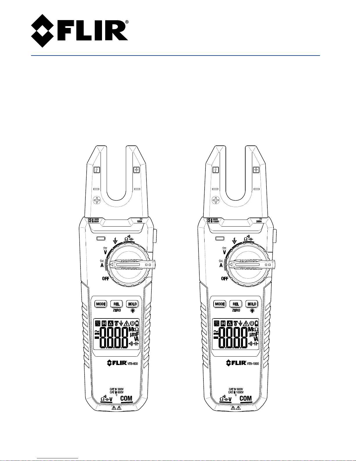
The VT8 series is a feature-packed Open Jaw True RMS Electrical Tester. The VT8-600 is a
100A/600V rated instrument while the VT8-1000 is rated for 200A/1000V.
Measure AC/DC voltage, AC/DC current, Resistance, Continuity, and Capacitance. This meter series
also includes a Non-Contact Voltage Detector (NCV).
Other functions include Data Hold, Relative/Zero mode, Worklight, LCD Backlight, and Auto poweroff (APO).
This device is shipped fully tested and calibrated and, with proper use, will provide years of reliable
service. Please visit our website (www.flir.com) to check for the latest version of this User Guide,
Product Updates, Product Registration, and Customer Support.
2.1 Features
6000 count (0 ~ 5999) digital display
LCD display with high/low intensity backlight
True RMS AC measurements
0.8% DCV accuracy
Data Hold freezes the displayed reading
Relative and DC Zero functions
Auto Power OFF (APO)
100A (VT8-600) and 200A (VT8-1000) AC/DC current measurements
600V (VT8-600) and 1000V (VT8-1000) AC/DC voltage measurements
Non-Contact Voltage Detector
Visual and audible continuity measurement alert
Low battery indicator
CAT III 1000V / CAT IV 600V (VT8-1000)
CAT III 600V / CAT IV 300V (VT8-600)
2.2 Accessories
The VT8 series includes test leads, a printed Quick Start guide, batteries, and carry pouch.
If items are missing, please contact your FLIR sales agent. If there is a need to replace the test
leads, please select test leads that meet or exceed these requirements: Double insulation, CAT III
1000V, CAT IV 600V, 10A (VT8-1000) or CAT III 600V, CAT IV 300V, 10A (VT8-600)
Page 5

5 VT8-600_1000-en-US_AA 10/18
3. Safety Information
To ensure the safe operation and service of the meter, follow these instructions closely. Failure to
observe warnings can result in severe injury.
This instrument is designed and produced in strict accordance with GB4793 Safety Requirements
for Electronic Measuring Apparatus and IEC61010-1 and IEC 61010-2-032 safety standards, and
complies with the safety standard of double insulation, over-voltage CAT III 1000V, CAT IV 600V
(VT8-1000) or CAT III 600V, CAT IV 300V (VT8-600) and pollution level 2. Please use this instrument
in strict accordance with the user manual and quick start guides, failure to do so could compromise
or defeat the provided protections.
Confirms to UL standards 61010-1, 61010-2-030, 61010-2-032, and 61010-2-033; Certified to CSA
standards C22.2 No. 61010-1, 61010-02-030, IE CSTD 61010-2-032, and 61010-2-033.
WARNINGS
WARNINGS identify hazardous conditions and actions that could cause BODILY HARM or DEATH.
When handling test leads or probes, keep hands and fingers behind the finger guards at all times. To
avoid electrical shock do not touch exposed electrical wire, connectors, unused input terminals, or
circuits under test.
Remove test leads from the meter before opening the battery compartment or meter housing.
Use the meter only as specified in this User Guide or accompanying Quick Manual to avoid
compromising the protections provided by the meter.
Be sure to use the proper terminals, switch positions, and ranges when taking measurements.
Verify the meter’s operation by measuring a known voltage. Have the meter serviced if the meter
responds unusually or if there are questions regarding the meter’s functional integrity.
Do not apply more than the rated voltage, as marked on the meter, between terminals or between any
terminal and earth ground.
Do not measure voltages above 1000V AC/DC (VT8-1000) or 600V AC/DC (VT8-600) between terminal
and ground to prevent electrical shock and damage to the electrical tester.
Use caution working with voltages above 30 VAC RMS, 42 VAC peak, or 60 VDC. These voltages pose a
shock hazard.
To avoid misleading readings that could lead to electric shock and injury, replace the batteries as soon as
the low battery indicator is displayed.
Disconnect power to the circuit under test and discharge all high-voltage capacitors before testing
resistance, continuity, diodes, or capacitance.
Do not use the meter in the presence of explosive gas or vapor.
To reduce risk of fire or electric shock, do not use the meter if it is wet and do not expose the meter to
moisture.
Individual protective equipment should be used if HAZARDOUS LIVE parts in the installation where
measurements are to be carried out could be accessible.
Page 6
6 VT8-600_1000-en-US_AA 10/18
CAUTIONS
CAUTIONS identify conditions and actions that could cause DAMAGE to the meter or equipment
under test. Do not expose the meter to extremes in temperature or high humidity.
Disconnect the test leads from the test points before changing the position of the function (rotary)
switch.
Do not expose the meter to extremes in temperature or to high humidity.
Never set the meter to the resistance, diode, capacitance, micro-amp, or amp functions when
measuring the voltage of a power supply circuit; this could result in meter damage and damage to the
equipment under test.
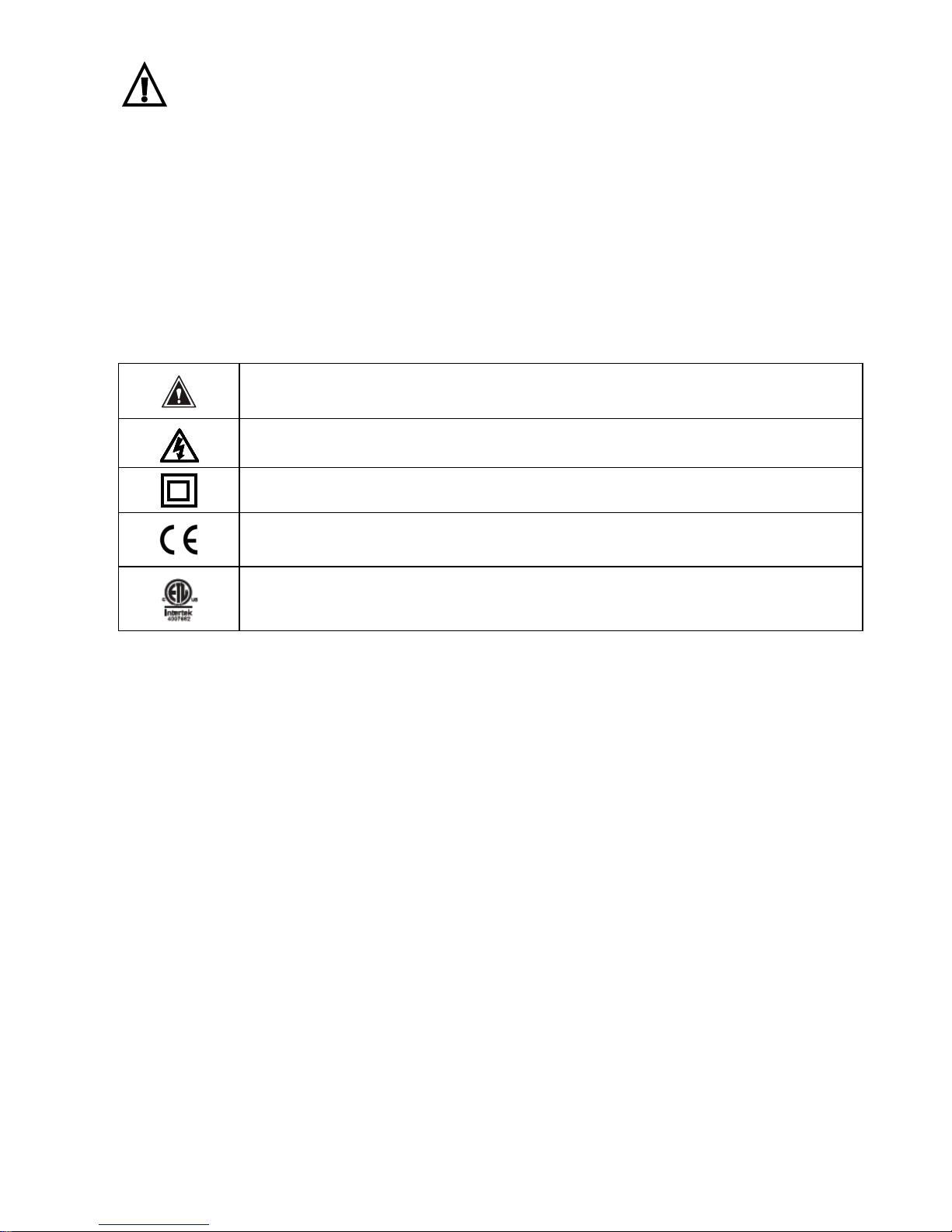
Safety Symbols
This symbol, adjacent to another symbol, indicates the user must refer to the
manual for further information
Risk of electrical shock
Equipment protected by double or reinforced insulation
Conforms to EU directives
ETL listed; complies with USA and Canada requirements
PER IEC1010 OVERVOLTAGE INSTALLATION CATEGORY
OVERVOLTAGE CATEGORY I
Equipment of OVERVOLT AGE CATEGORY I is equipment for connection to circuits in which measures are taken to limit the
transient over-voltages to an appropriate low level.
Note – Examples include protected electronic circuits.
OVERVOLTAGE CATEGORY II
Equipment of OVERVOLTAGE CATEGORY II is energy-consuming equipment to be supplied from the fixed installation.
Note – Examples include household, office, and laboratory appliances.
OVERVOLTAGE CATEGORY III
Equipment of OVERVOLTAGE CATEGORY III is equipment in fixed installations.
Note – Examples include switches in the fixed installation and some equipment for industrial use with permanent
connection to the fixed installation.
OVERVOLTAGE CATEGORY IV
Equipment of OVERVOLTAGE CATEGORY IV is for use at the origin of the installation.
Note – Examples include electricity meters and primary over-current protection equipment
Page 7

7 VT8-600_1000-en-US_AA 10/18
4. Descriptions
4.1 Meter Description
1. Non-Contact Voltage Detector
2. Open jaw hall effect Current sensor
3. NCV alert LED lamp
4. Worklight button
5. Rotary function switch
6. REL (Relative ) and ZERO button
7. MODE button
8. HOLD and LCD Backlight button
9. LCD Display
10. Test lead jacks
11. Worklight lens
12. Test leads in holders
13. Battery compartment
14. Compartment screw
Fig 4-1 METER DESCRIPTION
Page 8
8 VT8-600_1000-en-US_AA 10/18
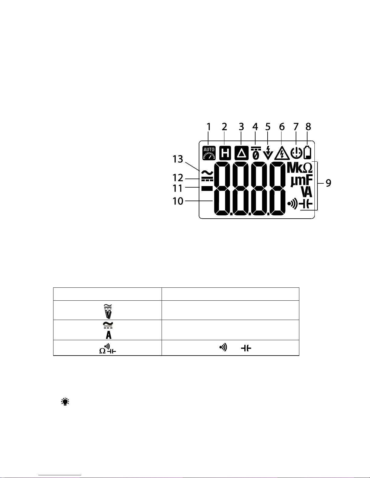
4.2 Display Icon Descriptions
1. Auto Range
2. Data Hold
3. Relative mode
4. DC Zero
5. Non-Contact Voltage detector
6. Electrical signal detected
7. Auto Power OFF (APO)
8. Battery status
9. Unit of measure and
measurement function icons
10. Main display digits
11. Minus (negative) sign
12. DC (direct current)
13. AC (alternating current)
Fig 4-2 METER DISPLAY
4.3 Push-Button Descriptions
MODE: Short press to step through the functions shown in the table below.
Fig. 4-3 MODE Button Function Table
Switch Position
Mode Button Function
AC < > DC
AC < > DC
Ω > > >
REL/ZERO: Short press to enter/exit the Relative mode. Relative mode is only available for
AC/DC voltage, AC Current, and Capacitance. In DCA mode, short press to zero the display;
long press to exit the zero function.
H : Data Hold (short press) and LCD backlight (long press for low intensity light, long press
again for high intensity light, long press again to switch lighting OFF). See the dedicated
paragraphs for Data Hold and Display Backlight in Section 5, Operation.
Page 9

9 VT8-600_1000-en-US_AA 10/18
4.4 Rotary Function Switch Description
OFF: Meter power OFF position
: AC/DC Current mode (press MODE to choose AC or DC)
: AC/DC Voltage mode (press MODE to choose AC or DC)
: Non-Contact Voltage Detect position
: Resistance, Continuity, and Capacitance (press MODE to select function)
5. Operation
CAUTION: Read and understand all of the Safety statements listed in the safety section of
this manual prior to use.
5.1 Meter Power ON/OFF
Turn the rotary function switch to any position to power the meter. Replace the batteries if the
unit fails to power ON (refer to the Maintenance section).
Turn the function switch to the OFF position to power OFF the meter.
The meter includes an Auto Power OFF feature (APO); the meter switches OFF after 15 minutes
of inactivity.
The low battery symbol
appears on the display when the battery voltage is insufficient.
5.2 Display Backlight
The LCD backlight has two intensity levels, low and high:
With the LCD backlight OFF, long press the
button to activate the low intensity backlight
With the low intensity backlight ON, long press the
button a second time to activate the high
intensity backlight
With the high intensity backlight ON, long press the button to extinguish the LCD backlight.
5.3 Worklight
With the meter powered ON, short press the Worklight button on the right side of the meter to
switch the Worklight ON or OFF. Excessive Worklight use will shorten battery life.
5.4 Data Hold
To freeze the LCD meter reading, short press the HOLD (Data Hold) button. While data hold is
active, the H display icon appears on the LCD. Short press HOLD to return to normal operation. The
H icon will switch OFF.
Page 10

10 VT8-600_1000-en-US_AA 10/18
5.5 Test Lead Considerations
Test lead probe covers can be removed for CAT II 1000V installations. Use the test lead probe
covers for CAT III 1000V and CAT III 600V installations. Do not measure voltages > 1000V AC/DC
(VT8-1000) or > 600V AC/DC (VT8-600). Remove the storage caps from the meter end of the test
leads before connecting the test leads to the meter.
5.6 Voltage Measurement Warnings and Cautions
WARNING:
Remove the test lead probe covers for CAT II 1000V installations. Use the test lead probe covers
for CAT III 1000V and CAT III 600V installations.
Do not measure voltages > 1000V AC/DC (VT8-1000) or 600V AC/DC (VT8-600).
CAUTION: When connecting the test leads to the circuit or device under test, connect the
black lead before the red; when removing the test leads, remove the red before the black lead.
Disconnect probes and circuit under test after all measurements are completed.
5.7 AC/DC Voltage Measurements
1. Insert the black test lead banana plug into the
negative (COM) jack and the red test lead banana
plug into the positive (V) jack.
2. Turn the function switch to the position. Use the
MODE button to select AC or DC.
3. Read the Warning and Caution statements above to
determine whether or not to use the test lead probe
covers.
4. Touch the test probe tips to the circuit under test.
For DC measurements observe the correct polarity
(red lead to positive, black lead to negative).
5. Read the digital value shown on the display. The
meter is Auto Ranging and therefore selects the
proper decimal point position. For DC, when the
polarity is reversed, the display will show the (-)
minus sign before the value.
6. The VT8-1000 is rated for 1000VAC/DC and the VT8-
600 is rated for 600VAC/DC.
Fig 5-1 AC and DC VOLTAGE MEASUREMENTS
Page 11

11 VT8-600_1000-en-US_AA 10/18
5.8 AC/DC Current Measurements
WARNING: Do not measure the current on a circuit when the voltage increases to more
than 1000V AC/DC (VT8-1000) or 600V AC/DC (VT8-600). This can cause damage to the
instrument and can cause injury to persons.
Fig 5-2 Test only one conductor
1. Ensure that the probe leads are disconnected from the meter.
2. Set the function switch to the position.
3. Use the MODE button to select AC or DC. For DC press ZERO to remove any residual
magnetism before testing a conductor.
4. Test only one conductor and position the conductor as close to the center of the jaw
opening as possible.
5. Read the current measurement in the display. The display will indicate the proper decimal
point and value. In DC, when the polarity is reversed, the display will show (-) minus
before the value.
6. The VT8-1000 is rated for 200A and the VT8-600 is rated for 100A maximum.
Page 12

12 VT8-600_1000-en-US_AA 10/18
5.9 Non-Contact AC Voltage Detector
WARNING: It is possible for voltage to be present in a circuit even if the meter does not
beep or flash the NCV LED lamp. Always verify meter operation on a known live AC current
circuit and verify that the batteries are fresh before use.
When the meter senses an AC Voltage or electromagnetic field > 100VAC, the following occurs:
The meter produces audible tones (beeps)
The LED lamp flashes ON and OFF
The display shows 1, 2, 3, or 4 dashes
The greater the electrical field strength, the faster the rate of the
audible tones, the flashing of the LED lamp, and the number of dashes
displayed. If the meter does not emit a tone or flash the LED, there is
still the possibility that voltage is present; please use caution.
1. Turn the function switch to the position to select Non-Contact
Voltage Detect mode.
2. Note that EF is displayed when in this mode. If the EF does not
display when the function switch is turned to the NCV position,
check the batteries and do not use the meter until EF is displayed.
3. To test, place the meter near a source of electrical energy. Note
that the tip of the meter offers the highest sensitivity.
4. Note the audible beeping, the flashing LED, and the displayed
dashes when a source of electrical energy is detected.
Fig 5-3 NON-CONTACT VOLTAGE DETECTOR
Page 13

13 VT8-600_1000-en-US_AA 10/18
5.10 Resistance Measurements
CAUTION: Switch OFF power to the device under test before measuring. Do not test on
circuits or devices where 60VDC or 30VAC is present.
1. Insert the black test lead banana plug into the negative (COM) jack. Insert the red test
lead banana plug into the positive (V/Ω) jack.
2. Turn the Function Switch to the position.
3. Press MODE to select the Ω icon on the display.
4. Touch the test probe tips across the circuit or part
under test. It is best to disconnect one side of the
part under test so the rest of the circuit will not
interfere with the resistance reading.
5. For resistance values, use the REL button (Relative
mode ) to remove test lead residual resistance.
6. Read the resistance value in the display. The display
will indicate the proper decimal point and value. If
the reading is out of range, the OL display icon will
appear.
Fig 5-4 RESISTANCE MEASUREMENTS
Resistance Measurement Notes:
The display will show “OL” when an open circuit is detected or if the resistance > maximum
range.
The test leads introduce an error of approx. 0.1Ω~0.2Ω for low resistance measurements.
Use the Relative mode to obtain accurate readings. Short the test leads together, press the
REL button, and then measure a low resistance. The meter subtracts the short-circuit value
from the reading.
If the test lead resistance of probe is > 0.5Ω when shorted, inspect the test leads and the
connection.
It may take several seconds for the reading to stabilize when measuring resistance >1MΩ.
This is normal operation.
For personal safety, do not measure a circuit with voltages > 30V DC or AC.
Page 14

14 VT8-600_1000-en-US_AA 10/18
5.11 Continuity Measurements
1. Insert the black test lead into the negative COM terminal and the red test lead into the
positive terminal.
2. Set the function switch to the position.
3. Use the MODE button to select the Continuity mode .
4. Touch the test probe tips across the wire or circuit under test.
5. If the resistance is < 10Ω, the beeper will sound continuously. If the resistance is between
10 and 100Ω the beeper may or may not sound. For an open circuit condition the meter will
display OL.
Fig 5-5 CONTINUITY MEASUREMENTS
Continuity Measurement Notes:
Turn off power to the circuit under test and discharge capacitors before measuring
continuity.
Open-circuit voltage is approx. -3.5V
Disconnect test leads and circuit measured after measurements are completed.
Page 15

15 VT8-600_1000-en-US_AA 10/18
5.12 Capacitance Measurements
WARNING: To avoid electric shock, remove power to the circuit under test and discharge
the capacitor under test before measuring. Do not test on circuits or devices where 60VDC or
30VAC is present.
1. Set the function switch to the
position.
2. Insert the black test lead banana plug into the
negative COM jack
and the red test lead banana plug into the positive
jack.
3. Press MODE to select the capacitance function .
4. Touch the test probe tips across the part under test.
5. For small capacitance values, use the REL button
(Relative mode ) to remove test lead and probe
capacitance.
6. Read the capacitance value in the display.
7. The display will indicate the proper decimal point and
value.
Fig 5-6 CAPACITANCE MEASUREMENTS
Capacitance Measurement Notes:
The display will show “OL” if a capacitor is short circuited or if the measured capacitance >
maximum range of the instrument.
Capacitance measurements > 600μF may require several seconds to obtain a stable
reading.
In order to ensure measurement accuracy, discharge residual charges before measuring
capacitance; Use maximum safety when working with high voltage capacitors to prevent
damage to the instrument and risk to personal safety.
Disconnect test leads and circuit under test after measurements are completed.
Page 16

16 VT8-600_1000-en-US_AA 10/18
6. Maintenance
WARNING: To avoid electrical shock, remove the test leads, disconnect the meter from any
circuit and turn OFF the meter before opening the case. Do not operate with an open case.
6.1 Battery Replacement
1. Turn meter OFF.
2. Remove the test leads from the meter.
3. Remove the Phillips head screw that secures the battery compartment cover on the back of
the meter.
4. Open the battery compartment and replace the two AA batteries, observing correct
polarity. Re-assemble the meter before use.
Battery Safety Notes: Please dispose of batteries responsibly; never dispose of batteries in a fire,
batteries may explode or leak. If the meter is not to be used for 60 days or more, remove the
batteries and store separately. Do not mix battery types or freshness levels; please use batteries
of the same type and of the same freshness level.
Never dispose of used batteries or rechargeable batteries in household waste.
As consumers, users are legally required to take used batteries to appropriate collection sites, the
retail store where the batteries were purchased, or wherever batteries are sold.
Disposal: Do not dispose of this instrument in household waste. The user is obligated to take end-of-life
devices to a designated collection point for the disposal of electrical and electronic equipment.
6.2 Cleaning and Storage
Periodically wipe the case with a damp cloth and mild detergent; do not use abrasives or solvents.
Please remove the batteries if the meter is stored for a long period of time.
Page 17

17 VT8-600_1000-en-US_AA 10/18
7. Specifications
7.1 Electrical Specifications
Accuracy is given as ± (% of reading + least significant digits) at 73.4F ±9F (23C ±5C) with
relative humidity <80%. Accuracy is specified for a period of one year after calibration.
Function
Range
Resolution
Accuracy
(reading)
‘OL’ Protection
AC Current
100A (VT8-600)
200A (VT8-1000)
0.1A
± (2.5% + 5 digits)
100A (VT8-600)
200A (VT8-1000)
True RMS, Frequency Response 50 ~ 60Hz
DC Current
100A (VT8-600)
200A (VT8-1000)
0.1A
± (2.5% + 5 digits)
100A (VT8-600)
200A (VT8-1000)
Use the DC Zero function to null the display reading
AC Voltage
6.000V
0.001V
± (1.2% + 5 digits)
600V (VT8-600)
1000V (VT8-1000)
60.00V
0.01V
± (1.2% + 3 digits)
600.0V
0.1V
± (1.5% + 2 digits)
1000V (VT8-1000)
0.1V
± (1.5% + 3 digits)
True RMS voltage applicable to 10% ~ 100% of the range
Input Impedance: ≥ 10MΩ; Frequency response 45 ~ 66Hz
DC Voltage
6.000V
0.001V
± (0.8% + 3 digits)
600V (VT8-600)
1000V (VT8-1000)
60.00V
0.01V
600.0V
0.1V
± (1.0% + 2 digits)
1000V (VT8-1000)
0.1V
± (1.0% + 3 digits)
Input Impedance: ≥ 10MΩ
Resistance
600.0Ω
0.1Ω
± (1.2% + 2 digits)
600V DC (VT8-600)
1000V DC (VT8-1000)
600V AC
6.000kΩ
0.001kΩ
± (1.0% + 2 digits)
60.00kΩ
0.01kΩ
600.0kΩ
0.1kΩ
6.000MΩ
0.001MΩ
± (1.2% + 2 digits)
60.00MΩ
0.01MΩ
± (1.5% + 5 digits)
Continuity
600.0Ω
0.1Ω
-----
< 10Ω beeper sounds. 10Ω to 100Ω undetermined. > 100Ω beeper off (OL
displayed). Open circuit voltage approx. 1.2V
Page 18

18 VT8-600_1000-en-US_AA 10/18
Function
Range
Resolution
Accuracy (reading)
‘OL’ Protection
Capacitance
60.00nF
0.01nF
± (4.0% + 20 digits)
600V DC (VT8-600)
1000V DC (VT8-1000)
600V AC
600.0nF
0.1nF
6.000µF
0.001µF
60.00µF
0.01µF
600.0µF
0.1µF
6.000mF
0.001mF
± (10%)
60.00mF
0.01mF
For reference only
Non-Contact
Volt Detector (NCV)
≥100Vrms; ≤10mm distance (LED/Buzzer alerts)
Page 19

19 VT8-600_1000-en-US_AA 10/18
7.2 General Specifications
Display Backlit 6000-count (0 ~ 5999) multi-function LCD
Display update rate 3 times/second, approximately
Polarity Automatic display of positive and negative polarity
Over-range indication “OL” or “-OL” is displayed
Open Jaw Sensor Type Hall Effect
Jaw opening 0.61” (15.5mm)
Electromagnetic field influence
Unstable or inaccurate readings may be displayed if there is an
electromagnetic field disturbance in the measurement environment
Maximum Voltage 1000V AC rms/DC (VT8-1000) or 600V AC rms/DC (VT8-600)
maximum applied to any terminal
Auto Power OFF After 15 minutes
Operating Temperature 14 ~ 122F (-10 ~ 50C)
Storage Temperature -22 ~ 140F (-30 ~ 60C)
Relative Humidity 95% maximum; 41 ~ 86F (5 ~ 30C)
75% maximum; 86 ~ 104F (30 ~ 40C)
45% maximum; 104 ~ 122F (40 ~ 50C)
Operating Altitude 6562’ (2000m)
Battery power 2 x 1.5V ‘AA’ alkaline batteries
Low battery indication is displayed if batteries need replacing
Weight 5.7 oz. (163.7g), including batteries
Dimensions (W x H x D) 8.27x 2.1 x 0.67” (210 x 53 x 35mm)
Safety Standards Complies with EN61010-1, EN61010-2-032, and EN61010-2-033
VT8-600: CAT III 600V, CAT IV 300V
VT8-1000: CAT III 1000V, CAT IV 600V
Pollution Degree 2
ETL Listed, RCM, cULus, CE
Drop Protection 6.6’ (2m) approx.
For Indoor Use
Page 20

20 VT8-600_1000-en-US_AA 10/18
8. Technical Support
Main Website
http://www.flir.com/test
Technical Support Website
http://support.flir.com
Technical support Email
TMSupport@flir.com
Service/Repair Support Email
Repair@flir.com
Support Telephone number
+1 855-499-3662 option 3 (toll-free)
9. Three-Year Limited Warranty
This product is protected by FLIR’s 3-Year Limited Warranty. Visit www.flir.com/testwarranty to
read the 3-Year Limited Warranty document. Register your product at the website to receive a
free 1-year warranty extension.
Page 21

21 VT8-600_1000-en-US_AA 10/18
Corporate Headquarters
FLIR Systems, Inc.
2770 SW Parkway Avenue
Wilsonville, OR 97070 USA
Telephone: +1 503-498-3547
Customer Support
Technical Support Website http://support.flir.com
Technical Support Email TMSupport@flir.com
Service and Repair Email Repair@flir.com
Customer Support Telephone +1 855-499-3662 option 3 (toll free)
Publication Identification No.: VT8-600_1000
Release version: AA
Release Date: October 2018
Language: en-US
Copyright © 2018 FLIR Systems, Inc.
All rights reserved including the right of reproduction in whole or in part in any form.
www.flir.com
 Loading...