

Page 1
User’s manual
FLIR VS70
High definition videoscope inspection camera
Page 2

Page 3

User’s manual
FLIR VS70
#T559827; r. AE/36943/36943; en-US
Page 4

Page 5

Table of contents
1 Disclaimers. . ... ... . .. . .. . .. . ... ... . .. . .. . ... ... . .. . .. . ... ... ... . .. . .. . .. 1
1.1 Copyright. .. . ... ... ... . .. . ... ... ... . .. . .. . ... ... ... . .. . .. . ... ... 1
1.2 Quality assurance .. ... . .. . .. . ... ... ... . .. . .. . ... ... . .. . .. . ... . 1
1.3 Documentation updates . . .. . .. . ... ... . .. . .. . ... ... . .. . .. . ... .. 1
1.4 Disposal of electronic waste. . ... ... ... . .. . .. . ... ... . .. . .. . ... . 2
1.5 FCC Compliance . . ... ... . .. . .. . ... ... . .. . .. . ... ... ... . .. . .. . .. 2
1.6 Industry Canada compliance .. . .. . ... ... ... . .. . .. . ... ... . .. . .. 3
2 Safety information . ... ... ... . .. . .. . ... ... . .. . .. . ... ... ... . .. . .. . ... ... . . 4
3 Introduction . . ... ... . .. . .. . ... ... ... . .. . .. . ... ... . .. . .. . ... ... ... . .. . .. . . 5
4 Description . .. . ... ... . .. . .. . ... ... . .. . .. . ... ... ... . .. . .. . ... ... . .. . .. . ... 6
4.1 Monitor ... ... ... . .. . .. . ... ... . .. . .. . ... ... . .. . .. . ... ... ... . .. . .. 6
4.1.1 Function buttons . . .. . ... ... . .. . .. . ... ... ... . .. . .. . .. 8
4.1.2 Display icons . . ... ... ... . .. . .. . ... ... ... . .. . .. . ... ... 8
4.2 Articulating probe . ... . .. . .. . ... ... ... . .. . .. . ... ... . .. . .. . ... ... 9
4.3 Wireless transmitter ... ... ... . .. . .. . ... ... . .. . .. . ... ... ... . .. .10
4.4 Probe accessories ... . .. . ... ... ... . .. . .. . ... ... . .. . .. . ... ... . .10
4.5 Probe. ... ... . .. . .. . ... ... . .. . .. . ... ... . .. . .. . ... ... . .. . .. . ... ..11
5 Operation ... . .. . .. . ... ... . .. . .. . ... ... . .. . .. . ... ... ... . .. . .. . ... ... . .. . .12
5.1 Basic operation . .. . .. . ... ... . .. . .. . ... ... ... . .. . .. . ... ... . .. . .12
5.1.1 Controlling the camera LED light
5.1.2 Taking a picture . . .. . .. . ... ... . .. . .. . ... ... . .. . .. . ..12
5.1.3 Recording a video. ... . .. . .. . ... ... . .. . .. . ... ... . .. .12
5.2 Setup menu . ... . .. . .. . ... ... . .. . .. . ... ... ... . .. . .. . ... ... . .. . .13
5.3 Factory Default Profiles menu . .. . ... ... ... . .. . .. . ... ... . .. . .. 14
5.4 Installing probe accessories. ... . .. . .. . ... ... . .. . .. . ... ... . .. .14
5.5 Articulating probe . ... . .. . .. . ... ... ... . .. . .. . ... ... . .. . .. . ... ..15
5.5.1 Articulating probe—wireless version . . ... ... . .. . .. 15
5.5.2 Articulating probe—direct version . ... ... ... . .. . .. . 16
5.6 Wireless transmitter ... ... ... . .. . .. . ... ... . .. . .. . ... ... ... . .. .17
5.6.1 Wireless transmitter—wireless version. ... . .. . .. . .17
5.6.2 Wireless transmitter—direct version . . ... ... . .. . .. 18
5.7 Managing stored pictures and videos.. ... ... . .. . ... ... ... . .. 19
intensity .. . ... ... . .. . .. . ... ... ... . .. . .. . ... ... . .. . .. 12
#T559827; r. AE/36943/36943; en-US v
Page 6

Table of contents
5.7.1 Viewing pictures and videos on the monitor
display .. . .. . ... ... . .. . .. . ... ... ... . .. . .. . ... ... . .. . .19
5.7.2 Transferring files to a PC ... ... . .. . .. . ... ... ... . .. . .19
5.7.3 Deleting the picture/video memory ... ... . .. . .. . ... 20
5.8 Video output to a TV or external monitor ... . .. . .. . ... ... . .. . .20
5.9 Reset.. ... ... . .. . .. . ... ... . .. . .. . ... ... . .. . .. . ... ... ... . .. . .. . .20
5.10 Rear stand . .. . ... ... . .. . .. . ... ... . .. . .. . ... ... . .. . .. . ... ... ... 20
6 Maintenance. .. . .. . ... ... . .. . .. . ... ... . .. . .. . ... ... ... . .. . .. . ... ... . .. . .21
6.1 Cleaning . . .. . ... ... ... . .. . .. . ... ... . .. . .. . ... ... ... . .. . .. . ... .21
6.2 Battery recharging . . ... ... ... . .. . .. . ... ... . .. . .. . ... ... ... . .. .21
7 Technical specifications . ... ... . .. . .. . ... ... . .. . .. . .. . ... . .. . .. . .. . ...22
7.1 Monitor ... ... ... . .. . .. . ... ... . .. . .. . ... ... . .. . .. . ... ... ... . .. . .22
7.2 Transmitter . ... ... . .. . .. . ... ... ... . .. . .. . ... ... . .. . .. . ... ... ... 23
7.3 Camera . . .. . .. . ... ... . .. . .. . ... ... ... . .. . .. . ... ... . .. . .. . ... ..23
7.4 Probes and cameras . . .. . ... ... . .. . .. . ... ... . .. . .. . ... ... ... .24
7.5 Earphone . . ... ... . .. . .. . ... ... ... . .. . .. . ... ... . .. . .. . ... ... . .. 24
7.6 Part numbers .. ... . .. . .. . ... ... . .. . .. . ... ... ... . .. . ... ... ... . .24
8 Technical support for external meters . . .. . ... ... ... . .. . ... ... ... . .. 27
9 FLIR Test and Measurement Limited 2 Year Warranty .. . .. . ... ... .28
#T559827; r. AE/36943/36943; en-US vi
Page 7

1 Disclaimers
1.1 Copyright
© 2016, FLIR Systems, Inc. All rights reserved worldwide. No parts of the software including source code may be reproduced, transmitted, transcribed or
translated into any language or computer language in any form or by any means,
electronic, magnetic, optical, manual or otherwise, without the prior written permission of FLIR Systems.
The documentation must not, in whole or part, be copied, photocopied, reproduced, translated or transmitted to any electronic medium or machine readable
form without prior consent, in writing, from FLIR Systems.
Names and marks appearing on the products herein are either registered trademarks or trademarks of FLIR Systems and/or its subsidiaries. All other trademarks, trade names or company names referenced herein are used for
identification only and are the property of their respective owners.
1.2 Quality assurance
The Quality Management System under which these products are developed
and manufactured has been certified in accordance with the ISO 9001 standard.
FLIR Systems is committed to a policy of continuous development; therefore we
reserve the right to make changes and improvements on any of the products
without prior notice.
1.3 Documentation updates
Our manuals are updated several times per year, and we also issue product-critical notifications of changes on a regular basis.
To access the latest manuals and notifications, go to the Download tab at:
http://support.flir.com
It only takes a few minutes to register online. In the download area you will also
find the latest releases of manuals for our other products, as well as manuals for
our historical and obsolete products.
#T559827; r. AE/36943/36943; en-US 1
Page 8

1 Disclaimers
1.4 Disposal of electronic waste
As with most electronic products, this equipment must be disposed of in an environmentally friendly way, and in accordance with existing regulations for electronic waste.
Please contact your FLIR Systems representative for more details.
1.5 FCC Compliance
This device complies with part 15 of the FCC Rules. Operation is subject to the
following two conditions:
1. This device may not cause harmful interference.
2. This device must accept any interference received, including interference
that may cause undesired operation.
This equipment has been tested and found to comply with the limits for a Class B
digital device, pursuant to part 15 of the FCC Rules. These limits are designed to
provide reasonable protection against harmful interference in a residential installation. This equipment generates, uses, and can radiate radio frequency energy
and, if not installed and used in accordance with the instructions, may cause
harmful interference to radio communications. However, there is no guarantee
that interference will not occur in a particular installation. If this equipment does
cause harmful interference to radio or television reception, which can be determined by turning the equipment off and on, the user is encouraged to try to correct the interference by one or more of the following measures:
• Reorient or relocate the receiving antenna.
• Increase the separation between the equipment and receiver.
• Connect the equipment into an outlet on a circuit different from that to which
the receiver is connected.
• Consult the dealer or an experienced radio/TV technician for help.
#T559827; r. AE/36943/36943; en-US 2
Page 9
1 Disclaimers
CAUTION
Exposure to Radio Frequency Radiation.
To comply with FCC/IC RF exposure compliance requirements, a separation
distance of at least 20 cm must be maintained between the antenna of this device and all persons. This device must not be co-located or operating in conjunction with any other antenna or transmitter.
WARNING
Changes or modifications not expressly approved by the party responsible for
compliance could void the user's authority to operate the equipment.
1.6 Industry Canada compliance
This device complies with Industry Canada licence-exempt RSS standard(s). Operation is subject to the following two conditions: (1) this device may not cause interference, and (2) this devicemust accept any interference, including
interference that may cause undesired operation of thedevice.
CAUTION
Exposure to Radio Frequency Radiation.
To comply with RSS 102 RF exposure compliance requirements, for mobile
configurations, a separation distance of at least 20 cm must be maintained between the antenna of this device and all persons. This device must not be colocated or operating in conjunction with any other antenna or transmitter.
#T559827; r. AE/36943/36943; en-US 3
Page 10
2 Safety information
Note Before operating the device, you must read, understand, and follow all in-
structions, dangers, warnings, cautions, and notes.
Note FLIR Systems reserves the right to discontinue models, parts or accessories, and other items, or to change specifications at any time without prior notice.
WARNING
Make sure that children cannot touch the device. The device contains dangerous objects and small parts that children can swallow. If a child swallows an
object or a part, speak with a physician immediately. Injury to persons can
occur.
WARNING
Do not let children play with the packing material. These can be dangerous for
children if they use them as toys.
CAUTION
For the Articulating Probe, do not operate the articulation knob with the probe
in a coiled configuration. This will cause damage to the articulation controls.
This symbol, adjacent to another symbol or terminal, indicates that
the user must refer to the manual for further information.
This symbol, adjacent to a terminal, indicates that, under normal
use, hazardous voltages may be present.
Double insulation.
#T559827; r. AE/36943/36943; en-US 4
Page 11

3 Introduction
Congratulations on your purchase of this FLIR VS70 video borescope.
This instrument is designed for use as a remote inspection device. It can be used
to peer into tight spots, and record and playback real-time video and images.
Typical applications include HVAC inspection, cable routing, and automotive/
boat/aircraft inspection. The monitor is designed with dual left- or right-handed
controls for maximum flexibility, and is available with a full line of accessories.
This borescope is shipped fully tested and, with proper use, will provide years of
reliable service.
#T559827; r. AE/36943/36943; en-US 5
Page 12
4 Description
4.1 Monitor
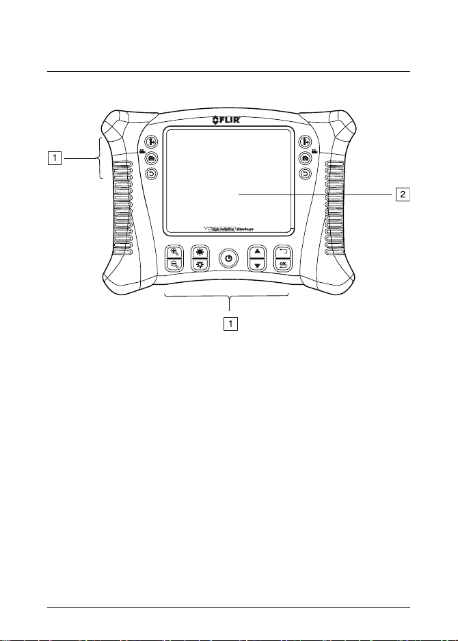
Figure 4.1 Monitor front view
1. Function buttons, see section 4.1.1 Function buttons, page 8.
2. Display.
#T559827; r. AE/36943/36943; en-US 6
Page 13

4 Description
Figure 4.2 Monitor rear view
1. Probe connector.
2. Rear stand.
Figure 4.3 Monitor bottom view, with access cover removed
1. USB connector.
2. Reset button.
3. SD card slot.
4. Video output jack.
5. Headset jack (audio and mic).
6. AC adapter connector.
#T559827; r. AE/36943/36943; en-US 7
Page 14

4 Description
4.1.1 Function buttons
For two-camera probe, press the button to toggle between the
side view and the front view camera lens.
• Press the button to take a picture.
• Press and hold down the button for 3 seconds to start/stop recording a video.
Press the button to rotate the display 90°.
Press the buttons to increase/decrease the display resolution.
Press the buttons to increase/decrease the camera LED light
intensity.
Press and hold down the button for 5 seconds to switch on/off the
monitor.
• Press the buttons to navigate up/down in the setup menu.
• Press the
• Press the button to open the setup menu.
• Press the button to select the highlighted menu item.
Press the button to exit the setup menu.
button to access the picture/video memory.
4.1.2 Display icons
Indicates that a picture is being taken.
Indicates that a video is being recorded.
Indicates the battery voltage status.
#T559827; r. AE/36943/36943; en-US 8
Page 15

4 Description
Indicates that a stored picture is being displayed.
Indicates that a stored video is being displayed.
Indicates playback of a stored video.
Indicates paused playback of a stored video.
4.2 Articulating probe
Figure 4.4 Articulating probe
1. Articulation knob (up/down).
2. Articulation knob (left/right).
3. Tension knob (left/right).
4. Articulating camera.
5. Tension knob (up/down).
6. Light intensity buttons.
7. Power button.
8. AC adaptor and extension cable sockets.
#T559827; r. AE/36943/36943; en-US 9
Page 16

4 Description
4.3 Wireless transmitter
Figure 4.5 Wireless transmitter
1. Probe connector.
2. Light intensity buttons.
3. Power button.
4. AC adaptor and extension cable sockets.
4.4 Probe accessories
Figure 4.6 Probe accessories
1. Anti-snag tip.
2. Magnet.
3. 45° mirror.
#T559827; r. AE/36943/36943; en-US 10
Page 17

4 Description
4.5 Probe
Figure 4.7 Probe
1. Camera.
2. Shaft.
3. Monitor connector.
#T559827; r. AE/36943/36943; en-US 11
Page 18

5 Operation
5.1 Basic operation
1. Insert an SD card into the SD card slot, located on the bottom of the monitor.
2. Connect the probe to the monitor or turn on the wireless adapter if applicable.
3. Press and hold down the
monitor.
4. If the battery indicator
monitor does not power on, recharge the battery. See section 6.2 Battery re-
charging, page 21.
5. Maneuver the probe into position to view the area to be examined. The probe
can be bent into the shape of the area to be examined. The optimum focus
distance is probe dependent.
6. For TWO-CAMERA PROBE, press the
side view and the front view camera lens. Two-camera operation requires a
direct connection of the dual channel cable (VSC2-58-1FM) to the VS70
monitor.
7. Use the
5.1.1 Controlling the camera LED light intensity
Note The camera LEDs become warm when set to maximum intensity.
1. In wireless mode, use the light intensity buttons on the articulating probe
(see Figure 4.4 Articulating probe, page 9) or wireless transmitter (see Figure 4.5 Wireless transmitter, page 10) to increase/decrease the light intensity.
2. In direct mode, use the
light intensity.
5.1.2 Taking a picture
1. Press the
icon is briefly displayed.
5.1.3 Recording a video
1. Audio can be recorded on the video via the microphone, located on the bottom of the monitor. For audio recording, remove the bottom access cover.
and buttons to zoom in and out.
button to take a picture and store it in the memory. The
button for 5 seconds to switch on the
shows that the battery voltage is low or if the
button to toggle between the
and buttons to increase/decrease the
#T559827; r. AE/36943/36943; en-US 12
Page 19

5 Operation
2. Press and hold down the button for 3 seconds (long press) to start the
video recording. The
3. While recording, you can take a picture by pressing the
icons are displayed.
button (short
press).
4. Press and hold down the
button for 3 seconds (long press) to stop the
video recording.
5.2 Setup menu
Monitor settings are adjusted in the setup menu.
DELETE ALL Delete all stored pictures and videos.
VIDEO OUTPUT For two-camera probe, select the front view or the
side view camera.
DATE/TIME SETUP Select the date and time format, set the date and
time, and select display on/off (when on, the date
and time are shown on the display and on the pictures/videos).
LANGUAGE Select the menu display language.
VIDEO FORMAT Set the video output to NTSC or PAL format.
Press either of the two camera buttons (upper right
or upper left button) to access the Factory Default
menu for camera brightness, contrast, hue, and
saturation settings. See section 5.3 Factory Default
Profiles menu, page 14 for more information.
AUTO POWER OFF Set auto power off to 5, 10, 15, or 30 minutes or
DISABLE.
INPUT SOURCE Set the input source to DIRECT or WIRELESS.
1. Press the
2. Press the
3. Press the
#T559827; r. AE/36943/36943; en-US 13
button to open the setup menu.
or button to navigate to the desired menu item.
button to select the highlighted menu item.
Page 20

5 Operation
4. Press the
or button to scroll through the options in an open menu
item.
5. Press the
6. Press the
or button to increase/decrease the selected value.
button to exit without saving.
7. After a change, do one of the following:
• Press the
• Press the
button to save the changed value.
button to exit without saving.
Note After 10 seconds of inactivity, the setup menu will exit without saving
any changes.
8. Press the
button to move up one step in the menu hierarchy and to exit
the setup menu.
5.3 Factory Default Profiles menu
The FLIR VS70 has two factory default profiles (Default1 and Default2) and one
user profile for brightness, contrast, hue, and saturation camera settings. To access the Factory Default menu, follow this procedure:
1. Navigate to the the VIDEO FORMATscreen in the setup menu as explained
in Section 5.2.
2. Press OK to open the TV OUTPUT NTSC/PAL selection screen
3. Press either of the camera buttons (top left or top right button) to access the
Factory Setup screen; The user profile settings will be shown, these can be
adjusted and saved by the user. Scroll down to Default1 or Default2 and
press OK to use one of the factory default profiles.
5.4 Installing probe accessories
Three accessories (mirror, anti-snag tip, and magnet) are supplied with each
probe.
#T559827; r. AE/36943/36943; en-US 14
Page 21

5 Operation
Figure 5.1 Installing probe accessories
1. Unscrew the probe ring.
2. Screw on the accessory.
5.5 Articulating probe
The articulating probe, with an adjustable tip angle, is used for improved viewing
angles and optimum inspection when the probe is inserted into the area to be examined. The articulating probe is available in a direct (wired) or wireless version.
Turn the articulation knobs to adjust the camera tip. The tension of an articulation
knob is adjusted by turning the corresponding tension knob. Refer to Figure 4.4
Articulating probe, page 9.
Note Do not operate the articulation knobs (see Figure 4.4 Articulating probe,
page 9) with the probe in a coiled configuration. This will damage the articulation
controls.
5.5.1 Articulating probe—wireless version
#T559827; r. AE/36943/36943; en-US 15
Page 22

5 Operation
Note The articulating probe battery must be fully charged for wireless opera-
tion. A weak battery may result in shut down of data transmission.
Note The FLIR VS70 wireless operation transmits on 2.4 GHz which may interfere with other equipment operating on this same frequency.
1. Connect the AC adaptor to the articulating probe and charge the battery if
necessary.
2. On the monitor, press and hold down the
button for 5 seconds to
switch on the monitor.
3. In the setup menu under INPUT SOURCE, select WIRELESS. Refer to section 5.2 Setup menu, page 13.
4. On the articulating probe, press and hold down the
button for 5 seconds to switch on the articulating probe. The camera video is displayed on
the monitor display.
5. Insert the probe into the area to be examined. Adjust the camera tip to the required viewing angle.
5.5.2 Articulating probe—direct version
1. Connect the articulating probe to the probe connector on the monitor, using
the supplied patch cable.
#T559827; r. AE/36943/36943; en-US 16
Page 23

5 Operation
2. On the monitor, press and hold press and hold down the
button for 5
seconds to switch on the monitor. The camera video is displayed on the
monitor display.
3. In the setup menu under INPUT SOURCE, select DIRECT. Refer to section
5.2 Setup menu, page 13.
4. Insert the probe into the area to be examined. Adjust the camera tip to the required viewing angle.
5.6 Wireless transmitter
The wireless transmitter is intended for use in areas that are difficult to access or
in situations where it is hard to maneuver the probe with the display attached.
The wireless transmitter can also be connected directly to the monitor using the
patch cord.
5.6.1 Wireless transmitter—wireless version
Note The wireless transmitter battery must be fully charged for wireless operation. A weak battery may result in shut down of the transmitter.
Note The FLIR VS70 wireless operation transmits on 2.4 GHz which may interfere with other equipment operating on this same frequency.
1. Connect the AC adaptor to the wireless transmitter and charge the battery.
2. Attach the probe to the wireless transmitter.
#T559827; r. AE/36943/36943; en-US 17
Page 24

5 Operation
3. On the monitor, press and hold down the
button for 5 seconds to
switch on the monitor.
4. In the setup menu under INPUT SOURCE, select WIRELESS. Refer to section 5.2 Setup menu, page 13.
5. On the wireless transmitter, press and hold down the
button for 5 seconds to switch on the transmitter. The camera video is displayed on the monitor display.
5.6.2 Wireless transmitter—direct version
1. Attach the probe to the wireless transmitter.
2. Connect the wireless transmitter to the probe connector on the monitor, using the supplied patch cable.
3. On the wireless transmitter, press and hold down the
button for 5 seconds to switch on both the transmitter and the monitor. The camera video is
displayed on the monitor display.
4. In the setup menu under INPUT SOURCE, select DIRECT. Refer to section
5.2 Setup menu, page 13.
#T559827; r. AE/36943/36943; en-US 18
Page 25

5 Operation
5.7 Managing stored pictures and videos
5.7.1 Viewing pictures and videos on the monitor display
1. Press the
2. Thumbnails of the pictures and videos are displayed. The
button to access the pictures and videos in the memory.
icon is dis-
played on video thumbnails.
3. Use the
and buttons to navigate through the picture/video thumb-
nails. The selected picture/video is framed.
4. To open the selected picture/video file, press the
The file number (e.g., IMG00005) and the
button.
icon (for pictures) or the
icon (for videos) are displayed.
5. To start playback of an open video file, press the
button. The icon
is displayed.
6. To pause the playback of a video, press the
button. The icon is
displayed.
7. To exit an open picture/video, press the
8. To exit the picture/video file memory, press the
button.
button.
5.7.2 Transferring files to a PC
There a two methods for transferring stored picture/video files to a PC:
• Remove the SD card from the monitor and insert it into the PC.
• Connect the monitor to the PC with a USB cable.
Pictures are saved in *.JPG format and videos in *.AVI format.
#T559827; r. AE/36943/36943; en-US 19
Page 26

5 Operation
5.7.3 Deleting the picture/video memory
1. In the setup menu, select DELETE ALL. Refer to section 5.2 Setup menu,
page 13.
The ERASE YES/NO box appears.
2. Press the
button to select YES. Press the button to delete all files
in the memory.
Press the
button to exit without deleting the file.
5.8 Video output to a TV or external monitor
The monitor can be set to output the high-quality video to a TV or other external
video monitor.
1. In the setup menu under VIDEO FORMAT, select PAL or NTSC to match the
TV/external monitor to be used. Refer to section 5.2 Setup menu, page 13.
2. Connect the video cable to the video output jack, located on the bottom of
the monitor. Connect the other end of the cable to the video input jack of the
TV or other external monitor.
The high-quality video image is displayed on the TV/external monitor.
5.9 Reset
If the monitor becomes unresponsive due to electromagnetic interference or other magnetic event, use a paper clip or other narrow object to press the Reset button, located on the bottom of the monitor.
5.10 Rear stand
The rear stand can be set to three positions: lower position (stored), middle position for bench viewing, and upper position for hanging.
#T559827; r. AE/36943/36943; en-US 20
Page 27

6 Maintenance
6.1 Cleaning
Clean the monitor, articulating probe, wireless transmitter, and accessories with
a damp cloth and mild detergent; do not use abrasives or solvents.
6.2 Battery recharging
1. Ensure that the monitor is switched off.
2. Connect the AC adaptor to the monitor.
3. After several hours, press the
The battery voltage status is indicated on the display:
• The battery is fully charged:
• The battery charging is still in process:
4. If the battery is fully charged, remove the AC adaptor and observe that the
fully charged four-bar indicator appears:
5. If the battery is not fully charged, press the
monitor and continue charging.
Note The battery will not charge properly if the monitor is switched on during
the charging cycle.
Note If the battery fails to charge, please contact FLIR Systems for battery replacement service. In order to maintain IP rating, the battery must be replaced by
authorized FLIR service personnel.
button to switch on the monitor.
.
.
.
button to switch off the
#T559827; r. AE/36943/36943; en-US 21
Page 28

7 Technical specifications
7.1 Monitor
LCD screen 145 mm (5.7″); viewable: 135 mm
Interface Mini USB 1.1 and AV out
Recording medium SD card
SD memory 4 GB standard (32 GB maximum)
Compression format MPEG4
Still image format JPEG (640 × 480)
Video recording format AVI (640 × 480)
Video output format NTSC and PAL; Frame rate 30 fps
Receiver frequency 2.4 GHz
Receiver sensitivity –87 dBm (SNR = 42 dB, F
Video system NTSC/PAL
Data
Audio type
Tripod mount On rear, accepts standard tripod
Battery 3.7 V rechargeable lithium polymer
Power adaptor 100–240 V input/5 V DC output
Ingress Protection IP67
Operating temperature –10 to 60℃ (14 to 140℉)
Storage temperature –40 to 80℃ (–40 to 176℉)
Operating humidity (maximum)
(5.3″)
Active matrix, 640 × 480 pixels
mod
kHz)
Video/audio
Stereo
screw
80%
= 15
#T559827; r. AE/36943/36943; en-US 22
Page 29

7 Technical specifications
Dimensions (W × D × H) 241 mm × 178 mm × 70 mm (9.5″ ×
7″ × 2.75″)
Weight 1.57 kg (3.46 lb.), including batteries
7.2 Transmitter
Frequency
2.4 GHz
Data Video/audio
Video system NTSC/PAL
Battery 3.7 V rechargeable lithium polymer
Power adaptor
100–240 V input/9 V DC output
Unobstructed effective range 10 m (32.5′)
Operating temperature –10 to 60℃ (14 to 140℉)
Storage temperature –40 to 80℃ (–40 to 176℉)
Dimensions (W × D × H) 190 mm × 70 mm × 63.5 mm (7.5″ ×
2.75″ × 2.5″)
Weight (approximate) 0.43 kg (0.95 lb)
7.3 Camera
Imaging Sensor CMOS
Video Format NTSC
Brightness Control Manual
Lamp Type LED
Interface Composite video
Ingress Protection IP67
Operating Temperature –10℃ to 50℃ (14 to 122℉)
#T559827; r. AE/36943/36943; en-US 23
Page 30

7 Technical specifications
7.4 Probes and cameras
Articulation 240 ± 20° manual tip articulation
Accessories Mirror, magnet and anti-snag ball (ex-
cluding 25 mm diameter cables)
7.5 Earphone
Plug
• 3.5 mm (0.14″)
• 4 rings
Speaker
• 15 mm (0.59″)
• 32 Ω
• 20~20 kHz
Microphone 6 × 5 mm (0.24″ × 0.2″)
Boom microphone, total length 10 cm (3.9″)
Color Black
Wire length 1.2 m (3.9′)
7.6 Part numbers
Part number Field of view Description
VST
VSA2-1-w
-
56°
Wireless 2.4 GHz VS70 transmitter
Wireless 2-way 6 mm (0.24″) articulating camera with 1 m (3.3′) probe
VSA2-2-w
56° Wireless 2-way articulating camera
with 2 m (6.6′) probe
VSA2-1
56°
2-way 6 mm (0.24″) articulating camera with 1 m (3.3′) probe
VSA2-2
56°
2-way 6 mm (0.24″) articulating camera with 2 m (6.6′) probe
#T559827; r. AE/36943/36943; en-US 24
Page 31

7 Technical specifications
Part number Field of view Description
VSC3.9-1FM
53°
3.9 mm (0.15″) camera with 1 m
(3.3′) flexible probe – QVGA via SF
VSC4.1-2RM
53°
4.1 mm (0.16″) camera with 2 m
(6.6′) SR probe – QVGA via SF
VSC5.8-1RM
56°
5. 8 mm (0.23″) camera with 1 m
(3.3′) SR probe – VGA via SF
VSC5.8-2RM
56°
5.8 mm (0.23″) camera with 2 m
(6.6′) SR probe – VGA via SF
VSC5.8-1R
56°
5.8 mm (0.23″) camera with 1 m
(3.3′) SR probe – VGA via LF
VSC5.8-2R
56°
5.8 mm (0.23″) camera with 2 m
(6.6′) SR probe – VGA via LF
VSC5.8-20
56°
5.8 mm (0.23″) camera with 20 m
(66′) FG probe – VGA via LF
VSC5.8-30
56°
5.8 mm (0.23″) camera with 30 m
(98′) FG probe – VGA via LF
VSC8.0-1R
56°
8 mm (0.31″) camera with 1 m (3.3′)
SR probe – VGA via LF
VSC8.0-2R
56°
8 mm (0.31″) camera with 2 m (6.6′)
SR probe – VGA via LF
VSC6.5-12S
56°
6.5 mm (0.26″) camera with 0.30 m
(12″) SS rigid probe – VGA via SF
VSC6.5-17S
56°
6.5 mm (0.26″) camera with 0.43 m
(17″) SS rigid probe – VGA via SF
VSS-20
VSS-30
-
-
Plumbing spool 20 m (66′)
Plumbing spool 30 m (98′)
#T559827; r. AE/36943/36943; en-US 25
Page 32

7 Technical specifications
Part number Field of view Description
VSC25
72°
25 mm (0.98″) camera with FG detachable probe – VGA via LF
VSC28
110°
28 mm (1.1″) camera with FG detachable probe – VGA via LF
#T559827; r. AE/36943/36943; en-US 26
Page 33

8 Technical support for external meters
Website http://www.flir.com/test
Technical support TMSupport@flir.com
Repairs Repair@flir.com
Phone number +1 855-499-3662 (toll-free)
#T559827; r. AE/36943/36943; en-US 27
Page 34

9 FLIR Test and Measurement Limited 2 Year Warranty
A qualifying FLIR Test and Measurement product (the
“Product”) purchased either directly from FLIR Commercial Systems Inc and affiliates (FLIR) or from anauthorized FLIR distributor or reseller that Purchaser registers
on-line with FLIR is eligible forcoverage under FLIR’s Limited Warranty, subject to the terms and conditions in this
document. This warranty onlyapplies to purchases of
Qualifying Products (see below) purchased and manufactured after April 1, 2013.
PLEASE READ THIS DOCUMENTCAREFULLY; ITCONTAINS IMPORTANT INFORMATION ABOUT THE PRODUCTS THAT QUALIFY FOR COVERAGEUNDER THE
LIMITED WARRANTY, PURCHASER’S OBLIGATIONS,
HOW TO ACTIVATE THEWARRANTY, WARRANTY
COVERAGE, AND OTHERIMPORTANT TERMS, CONDITIONS, EXCLUSIONS AND DISCLAIMERS.
1. PRODUCT REGISTRATION. To qualify forFLIR’s Lim-
ited Warranty, Purchaser must fully register the Product directly with FLIR on-line at http://www.flir.com within Sixty
(60) DAYS of the date the Product was purchased bythe
first retail customer (the “Purchase Date”). Qualifying
PRODUCTS THAT ARE NOTREGISTERED ON-LINE
WITHIN SIXTY (60) DAYS OF THE PURCHASE DATE
WILL HAVE A LIMITEDONE YEAR WARRANTY FROM
DATE OF PURCHASE.
2. QUALIFYING PRODUCTS. Uponregistration, Test and
Measurement products that qualify for coverage under
FLIR’s Limited Warrantyare: VS70 Videoscope, VSAxx
Articulation Camera, VSCxx Camera, VSSxx Probe Spool,
VST handset, MR02 Pin Extension Probe,and TAxx not
including accessories which may havetheir own warranty.
3. WARRANTY PERIODS. Theapplicable LimitedWar-
ranty Period measured from the Purchasedata are:
Products Limited Warranty
VS70, VSAxx, VSCxx,
VSSxx, VST, MR02,
TAxx
Any Product that is repaired or replaced under warranty is
covered under this Limited Warrantyfor one hundred
eighty days (180) daysfrom the date of return shipment
by FLIR or for the remaining duration ofthe applicable
Warranty Period, whichever is longer.
4. LIMITED WARRANTY. In accordance with theterms
and conditions of this Limited Warranty, and except as excluded or disclaimed in this document, FLIR warrants,
from the Purchase Date, that all fully registeredProducts
will conform to FLIR’s publishedproduct specifications
and be free from defects in materials andworkmanship
during the applicable Warranty Period. PURCHASER’S
SOLE AND EXCLUSIVE REMEDY UNDER THIS
Period
TWO (2) Years
WARRANTY, AT FLIR’S SOLEDISCRETION, IS THE REPAIR OR REPLACEMENT OF DEFECTIVE PRODUCTS
IN A MANNER, AND BYA SERVICE CENTER, AUTHORIZED BY FLIR. IF THIS REMEDY IS ADJUDICATEDTO
BE INSUFFICIENT,FLIR SHALL REFUND PURCHASER’S PAID PURCHASEPRICE AND HAVE NO OTHER
OBLIGATION OR LIABILITYTO BUYER WHATSOEVER.
5. WARRANTY EXCLUSIONSAND DISCLAIMERS.
FLIR MAKES NO OTHER WARRANTY OF ANYKIND
WITH RESPECT TO THE PRODUCTS. ALL OTHER
WARRANTIES, EXPRESS OR IMPLIED, INCLUDING
BUT NOT LIMITED TO IMPLIED WARRANTIES OF MERCHANTABILITY, FITNESS FOR A PARTICULAR PURPOSE (EVEN IF PURCHASER HAS NOTIFIEDFLIR OF
ITS INTENDED USE FOR THE PRODUCTS),AND NONINFRINGEMENT ARE EXPRESSLY EXCLUDEDFROM
THIS AGREEMENT.
THIS WARRANTY EXPRESSLY EXCLUDES ROUTINE
PRODUCT MAINTENANCE, SOFTWARE UPDATES,
AND REPLACEMENT OF FUSES,OR DISPOSABLE
BATTERIES.FLIR FURTHER EXPRESSLY DISCLAIMS
ANY WARRANTYCOVERAGE WHERE THE ALLEGED
NONCONFORMITY IS DUE TO NORMALWEAR AND
TEAR, OTHER ALTERATION, MODIFICATION, REPAIR,
ATTEMPTED REPAIR, IMPROPER USE, IMPROPER
MAINTENANCE, NEGLECT, ABUSE, IMPROPER STORAGE, FAILURETO FOLLOW ANY PRODUCT INSTRUCTIONS, DAMAGE (WHETHER CAUSED BY ACCIDENT
OR OTHERWISE), OR ANYOTHER IMPROPER CARE
OR HANDING OF THE PRODUCTS CAUSED BY ANYONE OTHER THAN FLIR OR FLIR’SEXPRESSLY AUTHORIZED DESIGNEE.
THIS DOCUMENT CONTAINS THE ENTIRE WARRANTY AGREEMENT BETWEEN PURCHASER AND
FLIR AND SUPERSEDES ALL PRIOR WARRANTY NEGOTIATIONS,AGREEMENTS, PROMISES AND
UNDERSTANDINGS BETWEENPURCHASER AND
FLIR. THIS WARRANTY MAY NOT BE ALTERED WITHOUT THE EXPRESS WRITTEN CONSENT OFFLIR.
6. WARRANTY RETURN, REPAIR AND REPLACEMENT. To be eligible for warrantyrepair or replacement,
Purchaser must notify FLIR within thirty (30) days of discovering of any apparent defectin materials or workmanship. Before Purchaser may returna Product for warranty
service or repair, Purchaser must first obtain areturned
material authorization (RMA) number from FLIR. To obtain
the RMA number Owner must provide an originalproof of
purchase. For additional information, to notify FLIRof an
apparent defect in materials or workmanship, or to request
an RMA number, visit http://www.flir.com. Purchaser is
solely responsible for complying with all RMA instructions
provided by FLIR including but not limited toadequately
packaging the Product for shipment to FLIR andfor all
packaging and shipping costs. FLIR will payfor returning
#T559827; r. AE/36943/36943; en-US 28
Page 35

9 FLIR Test and Measurement Limited 2 Year Warranty
to Purchaser any Product that FLIR repairs orreplaces
under warranty.
FLIR reserves the right to determine, in itssole discretion,
whether a returned Product is covered underWarranty. If
FLIR determines that any returned Product isnot covered
under Warranty or is otherwise excluded from Warranty
coverage, FLIR may chargePurchaser areasonable handling fee and return the Product to Purchaser, at Purchaser’s expense, or offerPurchaser theoption of handling the
Product as a non-warranty return.
7. NON-WARRANTY RETURN. Purchaser mayrequest
that FLIR evaluate andserv iceor repair a Product not covered under warranty, which FLIR may agree to do in its
sole discretion. Before Purchaser returns a Product for
non-warranty evaluation and repair, Purchaser must contact FLIR by visiting http://www.flir.com to request an evaluation and obtain an RMA. Purchaser is solely
responsible for complying with all RMA instructions provided by FLIR including but not limited to adequately
packaging the Product for shipment to FLIR andfor all
packaging and shipping costs. Upon receipt ofan authorized non-warranty return, FLIR will evaluate the Product
and contact Purchaser regarding the feasibility ofand the
costs and fees associated with Purchaser’srequest. Purchaser shall be responsible for the reasonable cost of
FLIR’s evaluation, for thecost of any repairs or services
authorized by Purchaser, and forthe cost of repackaging
and returning the Product to Purchaser.
Any non-warranty repair of a Productis warranted for one
hundred eighty days (180) days from the date of return
shipment by FLIR to be free from defectsin materials and
workmanship only,subject to all of the limitations, exclusions and disclaimers in this document.
#T559827; r. AE/36943/36943; en-US 29
Page 36

A note on the technical production of this publication
This publication was produced using XML — the eXtensible Markup Language.
For more information about XML, please visit http://www.w3.org/XML/
A note on the typeface used in this publication
This publication was typeset using Linotype Helvetica™ World. Helvetica™ was
designed by Max Miedinger (1910–1980)
LOEF (List Of Effective Files)
T501026.xml; en-US; AE; 36943; 2016-08-19
#T559827; r. AE/36943/36943; en-US 30
Page 37

Page 38

Website
last page
http://www.flir.com
Customer support
http://support.flir.com
Copyright
© 2016, FLIR Systems, Inc. All rights reserved worldwide.
Disclaimer
Specifications subject to change without further notice. Models and accessories
subject to regional market considerations. License procedures may apply.
Products described herein may be subject to US Export Regulations. Please
refer to exportquestions@flir.com with any questions.
Publ. No.: T559827
Release: AE
Commit: 36943
Head: 36943
Language: en-US
Modified: 2016-08-19
Formatted: 2016-08-19
 Loading...