


Voyager III
432-0005-00-12
Revision 100
September 2011
Installation Guide

© FLIR Commercial Systems, Inc., 2011. All rights reserved worldwide. No parts of this manual, in whole or in part, may be
copied, photocopied, translated, or transmitted to any electronic medium or machine readable form without the prior written
permission of FLIR Commercial Systems, Inc.
Names and marks appearing on the products herein are either registered trademarks or trademarks of FLIR Commercial
Systems, Inc. and/or its subsidiaries. All other trademarks, trade names, or company names referenced herein are used for
identification only and are the property of their respective owners.
This product is protected by patents, design patents, patents pending, or design patents pending.
The Voyager III thermal imaging system is controlled by US export laws. There are special versions of this system that are
approved for international distribution and travel. Please contact FLIR Systems if you have any questions.
FLIR Systems, Inc.
70 Castilian Drive
Goleta, CA 93117
Phone: +1.888.747.FLIR (+1.888.747.3547)
www.flir.com/maritime
Document Number: 432-0005-00-12, Revision 100
Document History
Revision Date Comment
100 September 2011 Initial Release
This document is controlled to FLIR Technology Level 1. The information contained in this document pertains to a dual use
product controlled for export by the Export Administration Regulations (EAR). FLIR trade secrets contained herein are
subject to disclosure restrictions as a matter of law. Diversion contrary to US law is prohibited. US Department of
Commerce authorization is not required prior to export or transfer to foreign persons or parties unless otherwise prohibited.
Warning: This is a Class A product. In a domestic environment this product may cause radio interference in
which case the user may be required to take adequate measures.

Contents
CHAPTER 1 Voyager III Installation ................................................................. 3
Additional References .................................................................................................................... 3
Documentation Conventions .......................................................................................................... 4
Warnings and Cautions............................................................................................... 4
Installation Overview. .................................................................................................. 5
Installation Planning. ................................................................................................... 6
Camera Location Planning ............................................................................................................. 6
Bulkhead Box Planning .................................................................................................................. 6
JCU Planning ................................................................................................................................. 7
Determine Component Locations and Cable Routing .................................................................... 7
Physical Installation..................................................................................................... 7
Voyager III Camera Body Handle ................................................................................................... 7
Voyager III Camera Body ............................................................................................................... 8
Voyager III Bulkhead Box ............................................................................................................... 9
Voyager III Joystick Control Unit (JCU) ........................................................................................ 10
Electrical Connections................................................................................................11
Proper Grounding ......................................................................................................................... 12
Main Sensor Cable ....................................................................................................................... 12
Ship Power, Ship Video, Ethernet, and NMEA ............................................................................. 19
NMEA Interface ............................................................................................................................ 20
Control Station Installation ............................................................................................................ 21
Digital Video Installation ............................................................................................................... 24
CHAPTER 2 Voyager III Reference ............................................................... 27
Introduction. .............................................................................................................. 27
Specifications. ........................................................................................................... 27
Parts and Accessories .................................................................................................................. 27
System Overview ......................................................................................................................... 29
External Standards.................................................................................................... 30
Acronyms. ................................................................................................................. 31
Installation Template. ................................................................................................ 31
432-0005-00-12 Rev 100 — Voyager III Installation Guide 1

Contents
2 432-0005-00-12 Rev 100 — Voyager III Installation Guide
CHAPTER 1 Voyager III Installation
This manual describes the physical mounting and electrical connection of the
Voyager III system. If you need help or have additional questions, call to speak
with our support experts; see the phone numbers on the back cover of this
manual.
Voyager III is a stabilized maritime thermal and visible-light camera system for
use on most types of vessels. Its state-of-the-art thermal imaging system provides
excellent night visibility and situational awareness, without any form of natural or
artificial illumination.
The Voyager III should be installed by a qualified marine electronics technician;
incorrect installation could void the warranty.
This manual includes information about the following topics:
• Installation overview and planning
• Mounting the camera and installing the bulkhead box and JCU
• Connecting the electronics
• Using the NMEA interface
• Parts list and general specifications, standards list, acronyms, and camera
installation template
Additional References
Your Voyager III camera comes with a complete documentation set on a CD
(FLIR Doc. # 432-0005-00-16) that includes this manual as well as others. All
documents are in PDF format and can be viewed with Adobe Acrobat Reader.
• Voyager III Operator’s Manual (FLIR Doc. # 432-0005-00-10) contains
information about how to configure, use, and operate the camera.
432-0005-00-12 Rev 100 — Voyager III Installation Guide 3
Warnings and Cautions
• Voyager III Quick Start Guide (FLIR Doc. # 432-0005-00-11) is a set of
double-sided cards that show the functions executed by the various JCU
buttons, puck movements, and on-screen symbols.
• Voyager III Interface Control Documents (ICD) is a set of CAD drawings with
detailed component dimensions, wiring schemes, and mounting dimensions.
There are three separate ICD documents:
• FLIR Doc. # 500-0385-19 contains dimensions of the maritime multi-
• FLIR Doc. # 432-0005-XX-19 contains drawings related to the Voyager III
• FLIR Doc. # 500-0483-19 contains the drawings for the bulkhead box,
The ICD drawings are also available from the FLIR Web site:
http://www.flir.com/cvs/americas/en/maritime/ae/
You may also refer to the Resources Web page for up-to-date documentation:
product JCU and a template to use while installing it.
camera body and the interconnections among system components.
including over all dimensions, component locations, and wiring.
http://www.flir.com/cvs/americas/en/maritime/resources/
Documentation Conventions
For safety, and to achieve the highest levels of performance from the Voyager III
system, always follow the warnings and cautions in this manual when handling
and operating the camera system.
Warning: Warning notices are used to emphasize that hazardous voltages,
currents, temperatures, or other conditions that could cause personal injury or
death exist with this equipment, or may be associated with its use.
Caution: Caution notices are used where equipment might be damaged if care is
not taken or an operation might have an unexpected outcome.
Note: Notes call attention to information that is especially significant to
understanding and operating the equipment.
Warnings and Cautions
Warning: Do not use the Voyager III imaging system as the primary navigation
system. Use it in conjunction with other navigation aids and a primary manual
navigation system.
4 432-0005-00-12 Rev 100 — Voyager III Installation Guide
Warning: Use of insufficient wire gauge can result in fire.

Installation Overview
Caution: Do not open the Voyager III camera unit for any reason. Disassembly of
the camera (including removal of the cover) can cause permanent damage and
will void the warranty.
Caution: Be careful not to leave fingerprints on the Voyager III camera optics.
Caution: The Voyager III requires a power supply of 24V DC nominal, 10
Amp maximum. Absolute voltage range: 21 – 32V DC. Operating the camera
outside of the specified input voltage range or the specified operating temperature
range can cause permanent damage.
This equipment must be disposed of as electronic waste. Contact your nearest
FLIR representative for instructions on how to return the product to FLIR for
proper disposal.
Installation Overview
The Voyager III system includes these standard components:
• Camera body
• “Non-flight” carrying handle and attaching screws
• Bulkhead box with connectors and terminal blocks
• NMEA interface board, installed in bulkhead box
• FLIR Video Tracker module, installed in bulkhead box
• Tracker bypass PCB, in a separate bag inside the bulkhead box
The bypass PCB is needed only if you want to operate the camera after
removing the tracker module.
• Main sensor cable, for connecting the camera body to the bulkhead box
• Joystick control unit (JCU) and cover
• Ethernet PoE cable (25 ft.)
• System power cable (10 ft.)
You need to supply:
• One 3/8 x 16 and six 1/4-20 stainless steel bolts and washers to secure the
Voyager III camera body—bolt length depends on mounting platform thickness
• Mounting hardware for securing the Voyager III bulkhead box
• One or more multi-function displays (MFD) or other analog video display
devices
432-0005-00-12 Rev 100 — Voyager III Installation Guide 5
• Coaxial RG59/U video cables (BNC at bulkhead box) to customer-supplied
video displays
Installation Planning
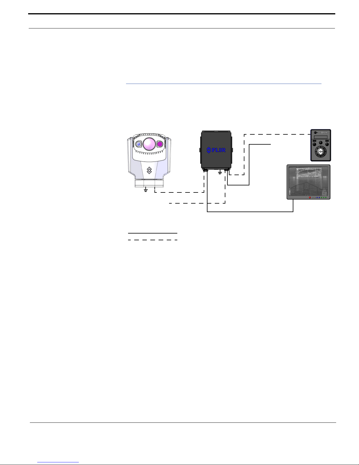
Camera Body
Bulkhead Box
JCU
Display
25 ft. Ethernet Cable
Ship Power
NMEA
To Voyager Video
Main Sensor
Customer-supplied cable
Cable shipped with system
Cable Legend
(Customer
supplied)
cable
Note: If an Ethernet cable longer than 25 ft.
is required, it is supplied by the customer.
FLIR recommends the use of shielded Ethernet cables.
• Ethernet cables (up to 100 ft.) to connect to the bulkhead box Ship Ethernet
Installation Planning
The following illustration shows a schematic of a basic Voyager III installation
with one Ethernet JCU, a NMEA connection, and one analog video display.
port, rated for use with PoE devices (IEEE802.3af), 8-conductor T568B
6 432-0005-00-12 Rev 100 — Voyager III Installation Guide
You should consider a number of factors in planning the locations for the key
Voyager III components: the camera body, bulkhead box, JCU, and cables.
Camera Location Planning
• Mount the Voyager III camera body as high as practical, but without interfering
with any radar, navigational, or communications electronics, and minimizing
the degree to which vessel structures block the camera’s 360° view. The
approximate camera weight is 50 lbs.
• Mount the Voyager III camera body as close to the vessel’s center line as
possible so you will have a symmetrical view of on-coming traffic, obstacles,
and other navigational hazards.
• Mount the camera body on a flat surface with the base on the bottom and the
camera on top. The camera body should not be hung upside down. Improper
mounts that are loose and/or resonate can magnify vessel impacts causing
the camera to be unable to maintain pointing direction.

Installation Planning
Bulkhead Box Planning
• Mount the bulkhead box in an area that is sheltered from the weather, has
• Ensure the box has access to power. The Voyager III system power cable
JCU Planning
• Mount the JCU in a convenient area close to the device that will be displaying
• Ensure the area you choose has enough room for the JCU body, connector,
• If you are relying on a magnetic compass for navigation and direction, you
• Optionally more than one JCU can be used to control the camera. If you are
good airflow, is not exposed to direct sunlight, and is within easy reach of all
required cables.
connecting the bulkhead box to ship’s power is 10 feet long.
the Voyager III system video.
and cable.
need to consider the “compass safe distance” when mounting the JCU. The
magnetic compass safe distance for the JCU is 21.7 inches (55 cm).
planning to use more than one JCU, you should consider the multiple locations
in your planning.
Determine Component Locations and Cable Routing
Caution: The Voyager III main sensor cable must maintain a secured minimum
bend radius of 5 inches where the cable is connected to the camera body. The
cable must be clamped at regular intervals to avoid excess motion, chafing, and
to provide strain relief to terminations when the boat is in motion.
• Route all cables and verify they are long enough given the proposed mounting
locations and cable routing requirements before you install any other
components.
• Verify that both sides of the mounting surface are accessible.
• Verify compliance with minimum keep-out volume, which is represented by a
cylinder 22 x 15.5 inches in diameter (see the camera diagram in the ICD).
• Verify compliance with minimum cable routing clearance as shown in the
bulkhead box diagram included in the ICD.
• Determine if any interior trim panels must be removed in order to gain access
to the mounting hardware, and if so, remove them ahead of time.
432-0005-00-12 Rev 100 — Voyager III Installation Guide 7
Physical Installation
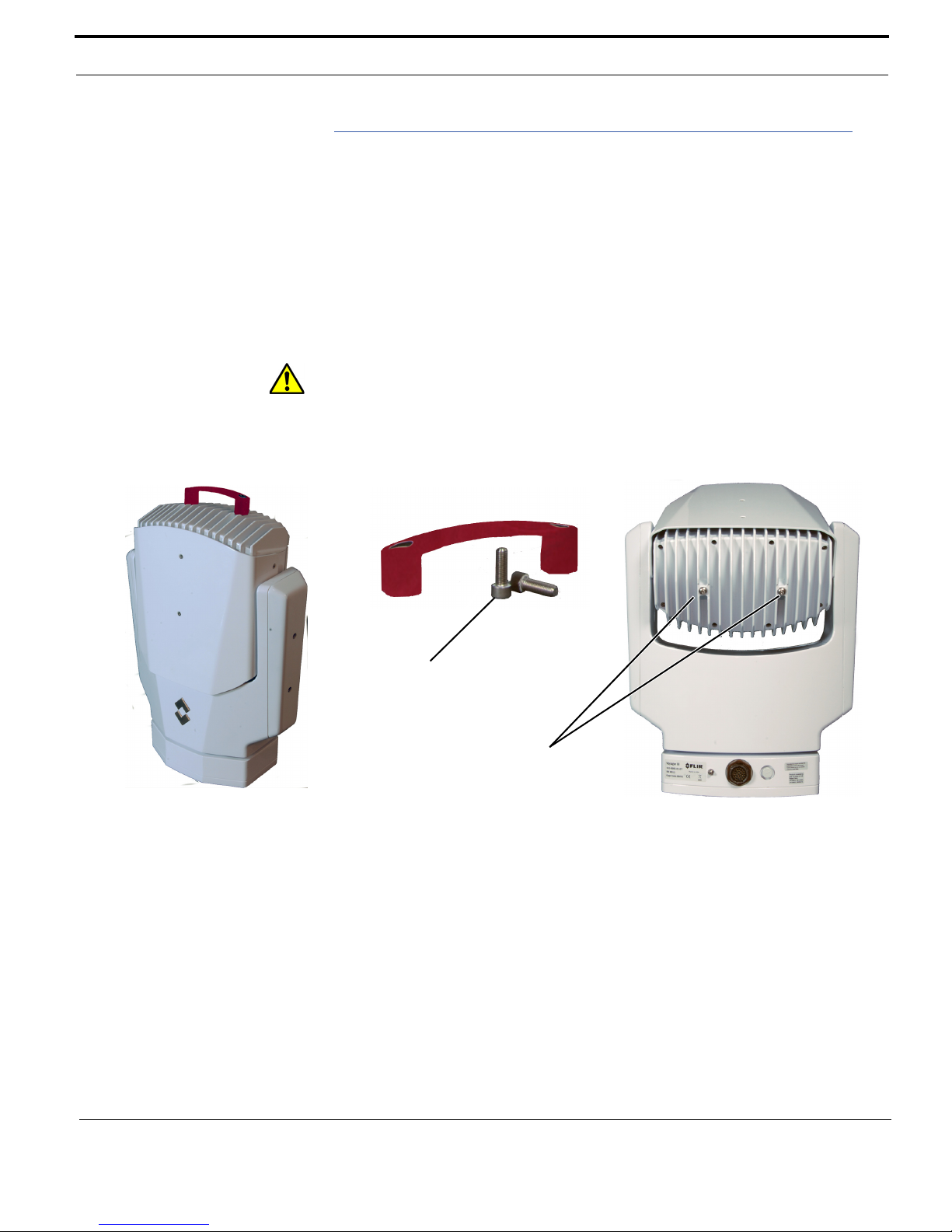
Socket-head screws
Button-head screws
(M8 x12 mm BHCS
18.8 Stainless)
(M8 x 25 mm SHCS
18.8 Stainless)
Physical Installation
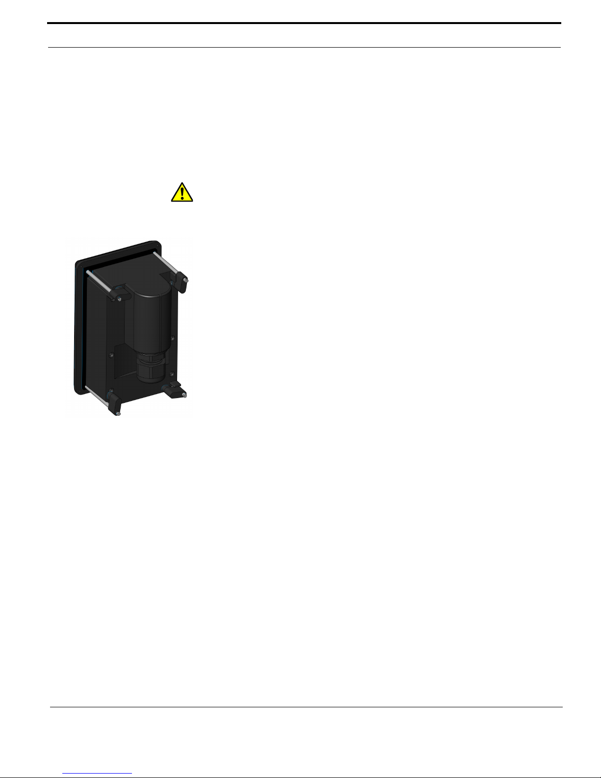
Voyager III Camera Body Handle
A red “non-flight” handle and bolts are supplied with the camera body to make it
easier to carry. Install the handle using the following procedure.
1. Using a 5.0 mm hex driver, remove the two button head screws from the rear
of the camera body.
2. Using a 6.0 mm hex driver, install the red handle and secure with the two
socket head screws supplied.
Caution: Ensure the red handle is removed from the Voyager III camera body
before making cable connections or applying power. Damage to the Voyager III
camera body may result if the handle is not removed.
When the camera body is mounted, remove the handle and socket-head screws
and replace the two button-head screws.
8 432-0005-00-12 Rev 100 — Voyager III Installation Guide
Voyager III Camera Body
• Using the template supplied on page 31 as a guide, mark the location of the
holes for mounting the camera body.
• Using customer-supplied stainless steel hardware, mount the Voyager III
camera body with six 1/4-20 bolts and washers and a 3/8 x 16 bolt in the
center for added support. All the bolts are required due to the weight of the
Voyager III camera body.
• Connect the main sensor cable to the camera body and verify the 5 inch
minimum bend radius after the cable is connected and secured.
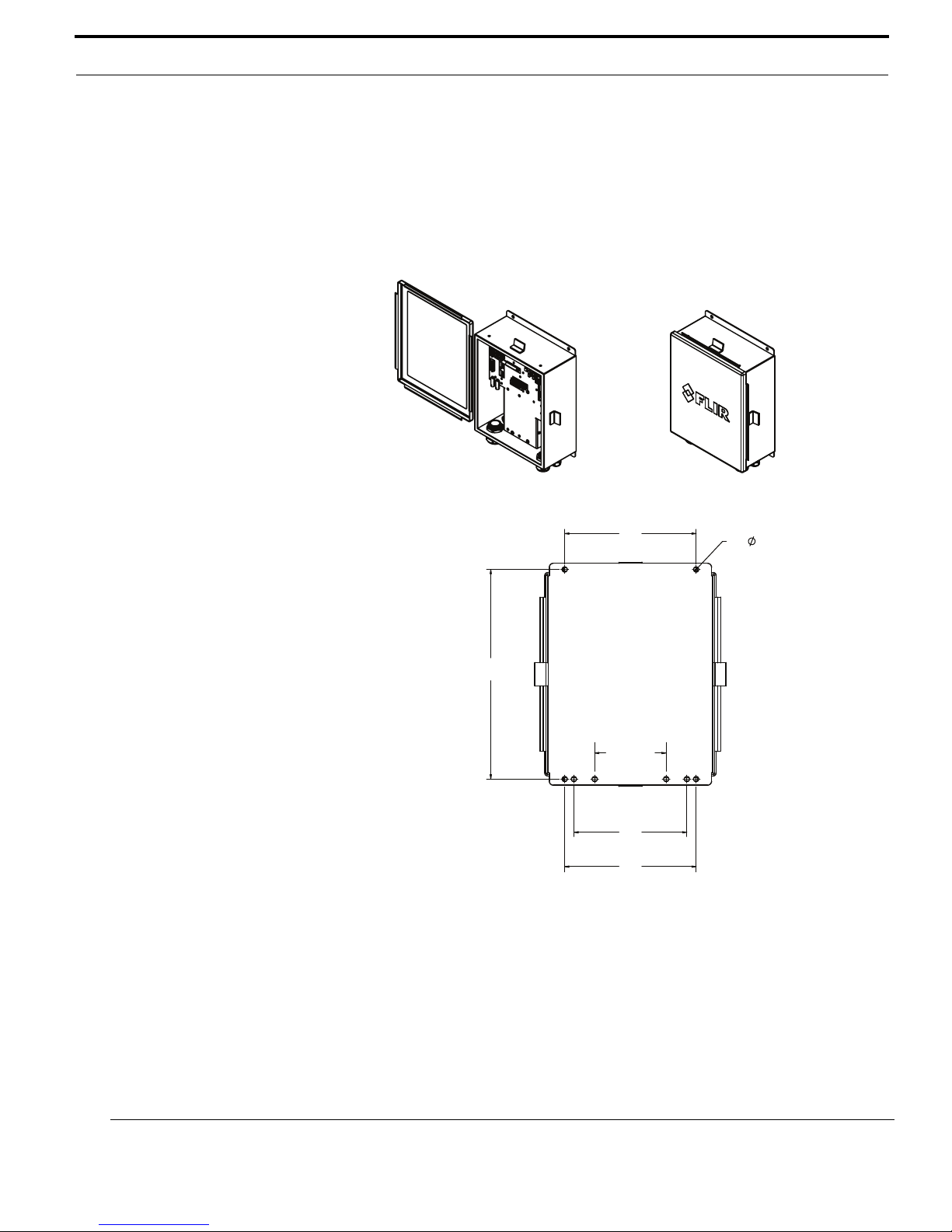
Physical Installation
203.20 mm
(8.00 in.)
203.20 mm
(8.00 in.)
174.61 mm
(6.87 in.)
110.49 mm
Recommended
(4.35 in.)
323.85 mm
(12.75 in.)
8X
7.92 mm (0.31 in.)
Bulkhead Box Mounting Dimensions
Voyager III Bulkhead Box
• Provide room for adequate service loops as depicted in the installation
drawings supplied.
• Using customer-supplied hardware, mount the Voyager III bulkhead box. Refer
to the bulkhead box drawings in the Voyager III ICD for detailed instructions.
432-0005-00-12 Rev 100 — Voyager III Installation Guide 9
Physical Installation
Voyager III Joystick Control Unit (JCU)
The cable gland seal is designed for use with double-shielded category 5
Ethernet cable. To ensure a good seal and to maintain compliance with EMI
ratings, a double-shielded cable is required.
The JCU enclosure is rated IP66 above the JCU mounting surface/gasket and
rated IP64 behind or below the gasket.
Caution: An installation template is provided in the JCU ICD (Doc. # 500-0385-
19). If you print the template from the PDF file, ensure that it was printed to the
correct scale by checking the dimensions prior to cutting any holes.
Standard JCU Mounting Instructions
1. Using the JCU template supplied as a guide in Doc. # 500-0385-19, mark the
location of the rectangular opening that will allow the JCU to be recessed in
the vessel’s control console. Ensure the corners are marked precisely and cut
square.
2. Apply the adhesive side of the rubber gasket to the back of the JCU on the
surface that faces the mounting platform. The JCU comes with 4 panel
mounting clamps that can be reversed when the thickness of the panel
material is less than 5/16 inches (0.31 in, 0.79 cm; see instructions below).
Ensure the mounting clamps are rotated inward and are recessed so the
entire JCU fits into the hole.
3. Remove boots from both ends of the Ethernet cable, as it may interfere with
the coupling gland. The boot may cause the RJ45 connector tab to depress,
which can lead to intermittent connections.
4. Loosen or remove the cable gland nut on the JCU, and insert the Ethernet
cable RJ45 connector through the gland nut. Once the Ethernet cable is
connected to the JCU, replace the gland nut and turn the nut 1/4 turn beyond
hand tight.
5. Insert the JCU into the hole and secure by turning the 4 corner screws
clockwise. Rotate each screw one full turn and ensure the mounting clamps
are rotated outward from the JCU housing. Tighten the screws to draw the
mounting clamps up against the mounting surface and then tighten another
quarter or half turn. Do not overtighten the screws.
Mounting the JCU to a Thin Panel
As shipped from the factory, the JCU can be mounted to dash thicknesses
ranging from 0.31 – 1.750 inches (0.79 – 4.45 cm). The clamps are set with the
small foot on the clamp facing away from the panel and toward the front of the
JCU, as shown below.
10 432-0005-00-12 Rev 100 — Voyager III Installation Guide
 Loading...