

VOYAGER II
INSTALLATION GUIDE
1

© FLIR Systems, Inc., 2009. All rights reserved worldwide. No parts of this manual, in whole or in part,
may be copied, photocopied, translated, or transmitted to any electronic medium or machine readable
form without the prior written permission of FLIR Systems, Inc.
Names and marks appearing on the products herein are either registered trademarks or
trademarks of FLIR Systems, Inc. and/or its subsidiaries. All other trademarks, trade names, or
company names referenced herein are used for identifi cation only and are the property of their
respective owners.
This product is protected by patents, design patents, patents pending, or design patents pending.
The Voyager II imaging system is controlled by US export laws. There are special versions of this system
that are approved for international distribution and travel. Please contact FLIR Systems if you have any
questions.
FLIR Systems, Inc.
70 Castilian Drive
Goleta, CA 93117
Phone: +1.888.747.FLIR (+1.888.747.3547)
www.fl ir.com
Document Number: 432-0002-00-11, rev 110
Document History
Revision Date Comment
100 Feb 2008 Initial Release
110 Jan 2009 Voyager II: includes NMEA interface, updated drawings, added TOC
and page numbers, other minor changes
This document is controlled to FLIR Technology Level 2. The information contained in this document
pertains to a dual use product controlled for export by the Export Administration Regulations (EAR).
FLIR trade secrets contained herein are subject to disclosure restrictions as a matter of law. Diversion
contrary to US law is prohibited. US Department of Commerce authorization is not required prior to
export or transfer to foreign persons or parties unless otherwise prohibited.
2

Contents
VOYAGER II INSTALLATION 4
Introduction 4
Installation Preparation 4
Prior to Cutting/Drilling Holes 4
PHYSICAL INSTALLATION 5
Voyager II Camera Body 5
Voyager II Bulkhead Box 5
Voyager II Joystick Control Unit (JCU) 5
ELECTRICAL INTERCONNECT 6
Main Sensor Cable 6
Installation Steps 6
NMEA INTERFACE 14
References 14
NMEA INTERFACE INSTALLATION 14
NMEA Installation Card 14
Connector Slot 14
NMEA Interface Wiring 15
Spare JCU Slot (1 or 2 JCUs in use) 15
Pigtail Connection (3 JCUs in use) 16
Electrical Checkout 16
Testing the NMEA Interface 17
DRAWINGS & INSTALLATION TEMPLATES 18
CONNECTIONS QUICK REFERENCE 18
3

VOYAGER II INSTALLATION
Introduction
Thank you for buying your new Voyager II! This manual describes the physical mounting and electrical
connection of the Voyager II camera. If you need help during the installation process, call 888.747.3547
to speak with one of FLIR’s Applications experts. The Voyager II should be installed by a qualifi ed marine
electronics technician, as incorrect installation could void the warranty.
The Voyager II comes with these standard components:
• Camera Body
• Bulkhead Box
• NMEA Interface Board (in a separate bag inside the Bulkhead Box)
• 50’ or 100’ main sensor cable (depending on what you ordered) - connects
the Camera Body to the Bulkhead Box
• Joystick Control Unit (JCU) with 100’ cable that connects to the Bulkhead Box
• System Power cable (10’)
• Voyager Documentation Package
You may need to supply:
• 16- gauge electrical wire; up to 100’ (3-conductor, for system power)
• Six (6) ¼-20 stainless steel bolts for attaching the Voyager II Camera Body. Note that bolt
length may be dependant on mounting platform thickness
• Four (4) bolts or screws for attaching the Bulkhead Box as required
• Miscellaneous electrical hardware, connectors and tools
If using the NMEA interface features, you will need to provide a 2-wire serial cable to the Bulkhead
Box from your NMEA device.
Installation Preparation
• Find a good place to mount the Voyager II’s components:
o Mount the Voyager II as high as practical, but without interfering with any radar,
navigational or communications electronics, and minimizing the degree to which
vessel structures block the camera’s view.
o Mount the Voyager II as close to the vessel’s centerline as possible so you will have
a symmetrical view of on-coming traffi c.
o Voyager II should be mounted on a fl at surface with the base on the bottom and the
camera on top. Do not hang the Voyager II upside down; the picture will display
upside down, and you may damage the Voyager II.
Prior to Cutting/Drilling Holes
• Once the mounting location has been selected, verify both
sides of the mounting surface are accessible.
• Determine if any interior trim panels must be removed in order to gain access to the
mounting hardware, and remove them ahead of time.
When selecting a mounting location for the Voyager II, consider cable lengths and routing. Ensure •
the cables are long enough, given the proposed mounting locations and cable routing requirements, and route the cables before you install the components.
4
PHYSICAL INSTALLATION
Voyager II Camera Body
Using the template supplied with this Installation Manual as a guide,
mark the location of the holes for mounting the Voyager II. Make sure the
template is aligned so that the Voyager II will point straight ahead, and that
the cable will exit towards the stern of the vessel.
Mount the Voyager II’s camera body with 6 1/4x20 bolts and washers.
There is also a 3/8x16 center insert which can be used for added support.
Voyager II Bulkhead Box
NOTE:
FLIR recommends that you terminate all cable ends inside the Bulkhead Box BEFORE you mount
it. Refer to the section on detailed cable preparation and termination for these instructions.
Mount the Bulkhead Box in an area that:
• Is sheltered from the weather
• Has good airfl ow
• Is not exposed to direct sunlight
• Is within easy reach of all required cables
• Provides room for adequate service loops as depicted in the installation drawings supplied
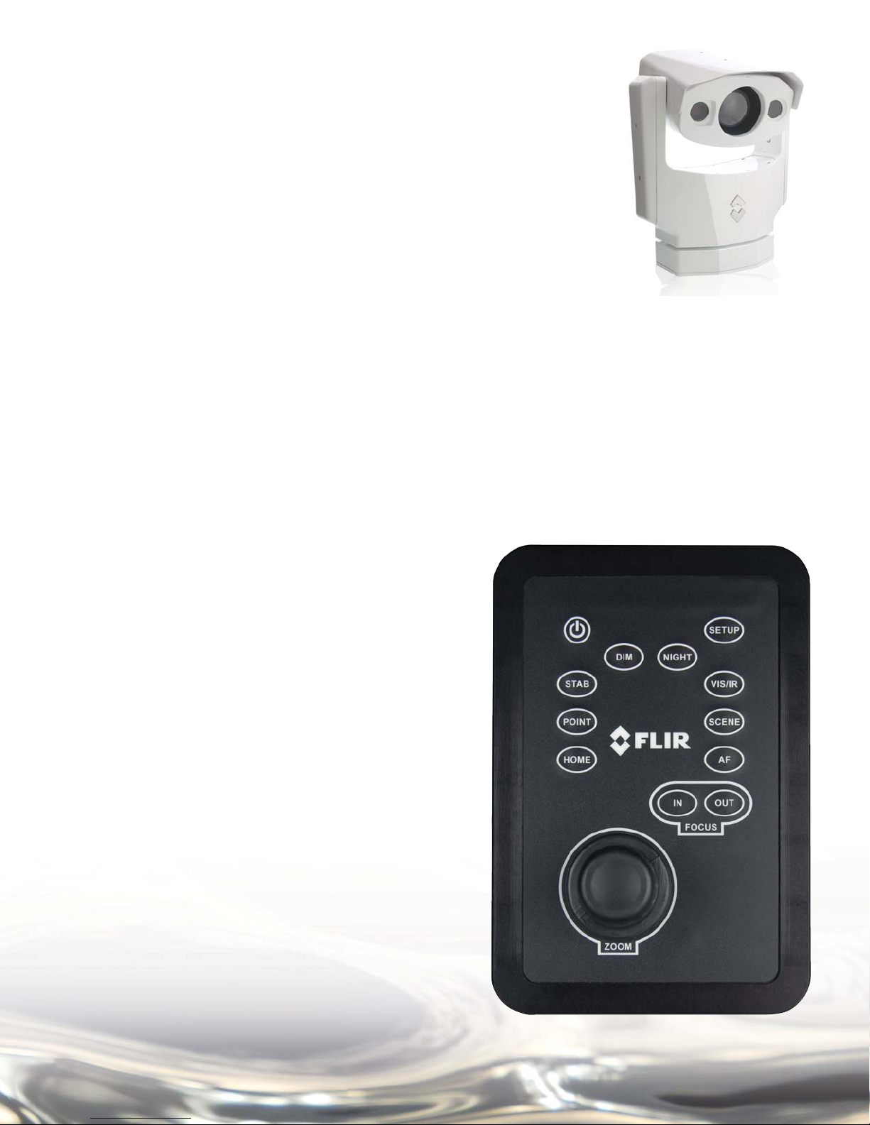
Voyager II Joystick Control Unit
(JCU)
Mount the JCU in a convenient area that is close
to the monitor that will display the Voyager II video
output. Make sure the area you choose will leave
enough room for the connector and cable under
the JCU (refer to the drawing package supplied for
dimensions).
Using the template supplied with the Installation
Manual as a guide, mark the locations of the holes to
be cut and drilled for the JCU.
Cut the hole that will allow the JCU to be recessed
in the vessel’s control console per the installation
drawings supplied, and drill the holes for the four
mounting studs.
Route the JCU cable through the JCU munting hole.
Connect the terminated end of the cable to the JCU,
insert the JCU into its mounting location and secure
with the supplied mounting studs.
5
The following sections (Electrical Interconnect and NMEA Interface) describe the connections to the
Voyager. Refer to the NMEA 0183 Standard for details on interconnecting the Voyager II with other
marine electronic devices.
ELECTRICAL INTERCONNECT
Main Sensor Cable
After routing the main sensor cable between the Camera Body and the Bulkhead Box, install the
Camera Body and connect the terminated end of the main sensor cable to the connector on the back
of the Camera Body’s base.
This section describes the procedures required to prepare the main sensor cable, JCU cable and main
power cable for termination inside the Bulkhead Box. The following tools and documents are recommended to complete the job:
• The installation drawings and templates (FLIR p/n 432-0002-00-19) at the end of this manual
• Ruler or measuring tape
• Exacto knife
• Scissors
• Wire cutter
• Wire stripper for 20 gauge wires
• Crimping tool for BNC connector
• Channel locks
• 2mm fl athead screw driver
Installation Steps
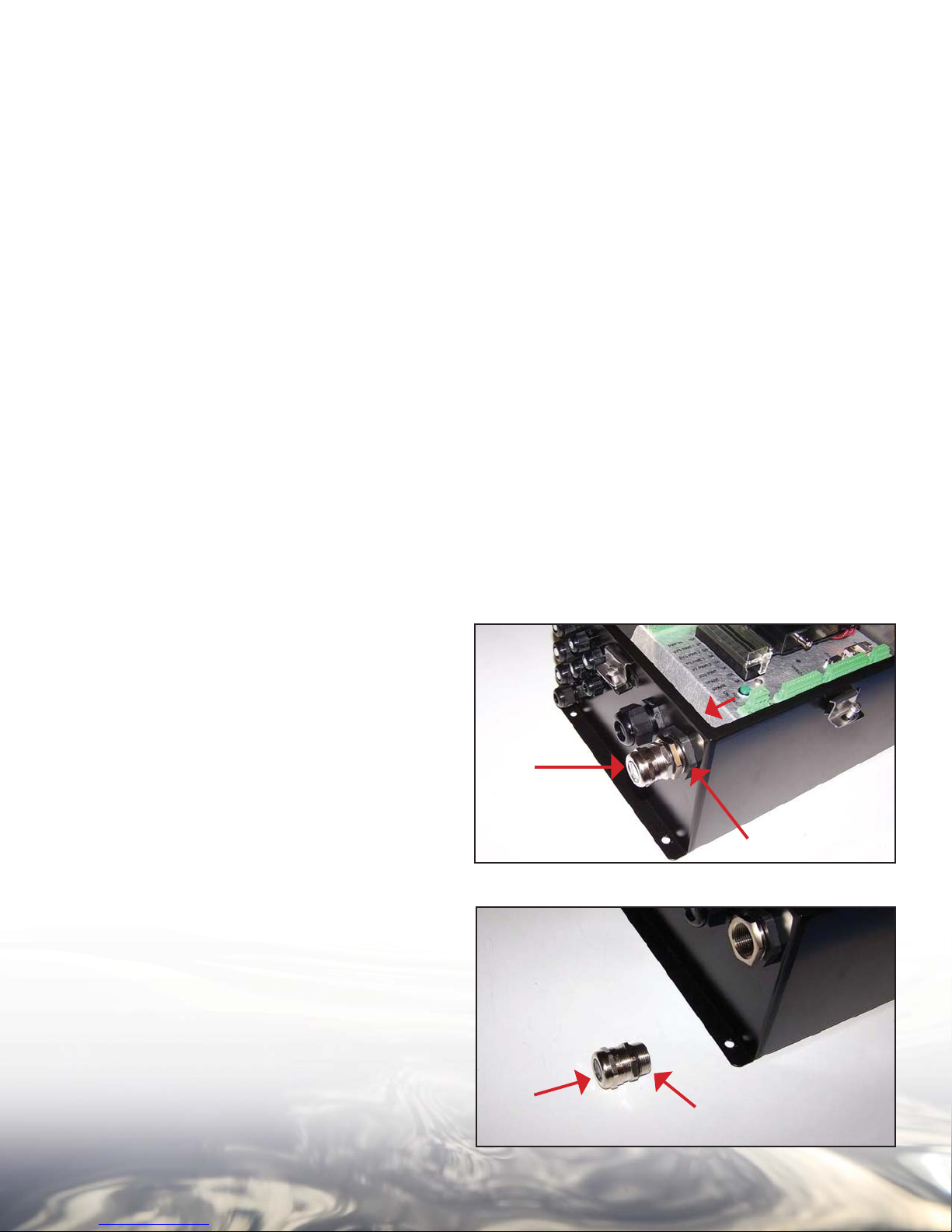
Step 1:
Remove the main sensor cable feed
through grommet
(A) by unscrewing it
from the lock nuts (B) and (C) on the
Bulkhead Box.
Step 2:
Unscrew the grommet cap
gland
(B) to expose the grommet seal
(A) from the cable
C
A
B
A
B
6
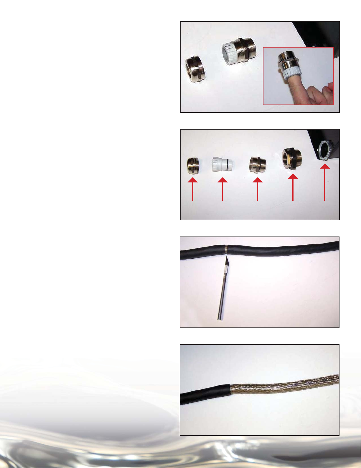
Step 3:
Remove the grommet seal from the cable
gland by inserting a fi nger and pulling it out.
Step 4:
Now that the grommet cap
(A), seal (B),
and cable gland (C) have been disassembled,
remove the other sections of the grommet
from the front of the Breakout Box,
including the 1” reducer (D), and the inner lock
nut (E).
Step 5:
Now prepare the main cable ends for attachment to the inside of the Bulkhead Box. As
directed by the drawing supplied in this Installation Manual, measure 13.5” from the end of
the cable, carefully cut around the outer black
cable jacket until you can slide it off, and remove it. Be careful not to cut into the metal
braid beneath the outer jacket.
AB C D E
Step 6:
Slide the black outer jacket off the cable,
exposing the inner metal braid
7

Step 7:
Push the braid back over the black outer jacket an inch or two, creating an area of slack in
the braid. Carefully insert scissor tips into the
braid, and cut all the way around it as shown.
Slide the excess braid off the cable and discard it
Step 8:
Working with the shorter length of braid, trim
it so that only 1” extends beyond the black outer jacket as shown.
Step 9:
Slide the grommet cap
(A – not shown), seal
(B), and cable gland (C) over the cable
Step 10:
Slide the grommet seal up the cable so that
the front edge just lines up with the end of the
black outer cable jacket as shown
A
B
C
8
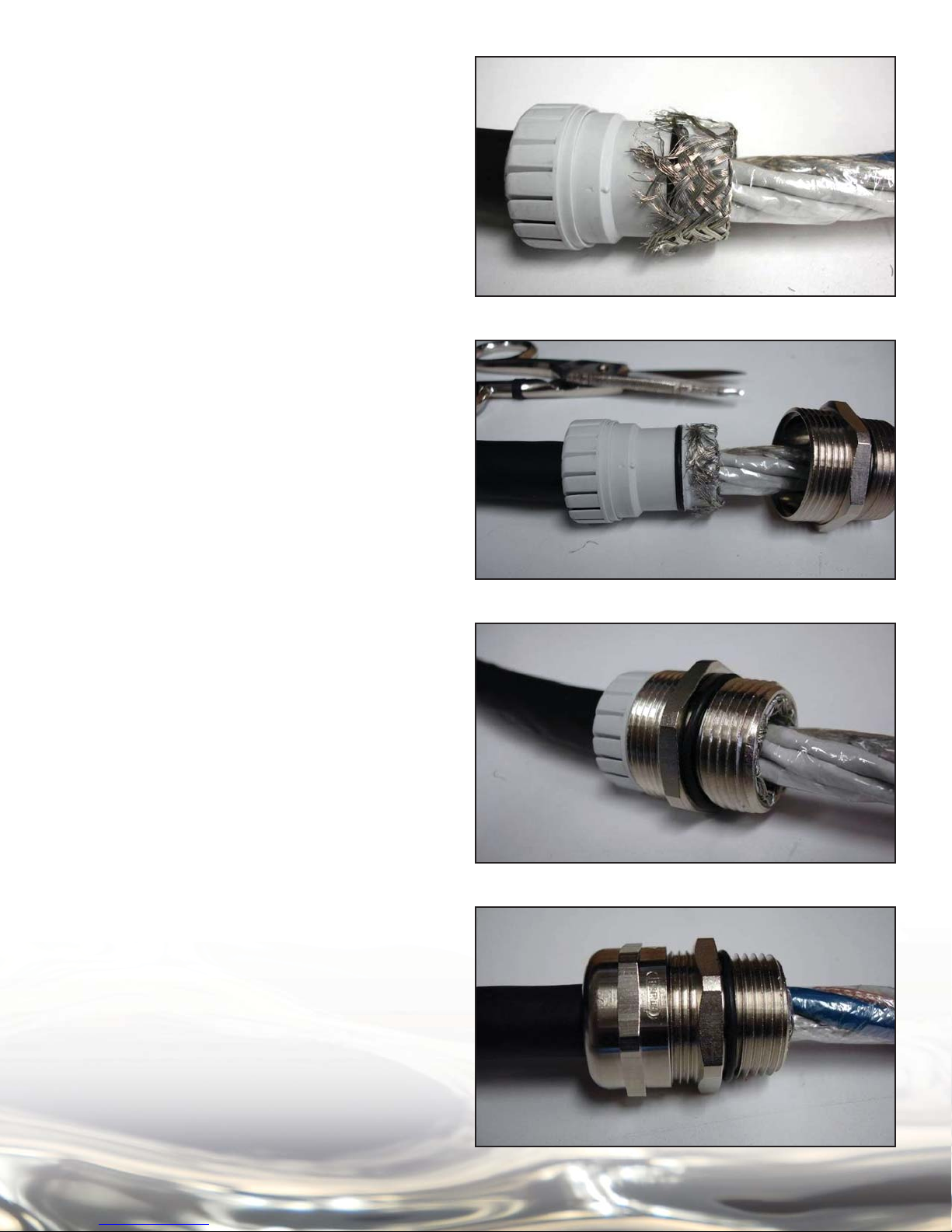
Step 11:
Carefully fold the metal braid back over the
grommet seal as shown
Step 12:
Trim the metal braid as shown, so that the
black o-ring seal is clear of the metal braid.
Step 13:
Slide the cable gland over the grommet seal
as shown, capturing the metal braid between
the two
Step 14:
Screw the grommet cap onto the cable gland
as shown.
You are now ready to prepare the cable ends
for connection to the Bulkhead Box’s internal
termination blocks
9
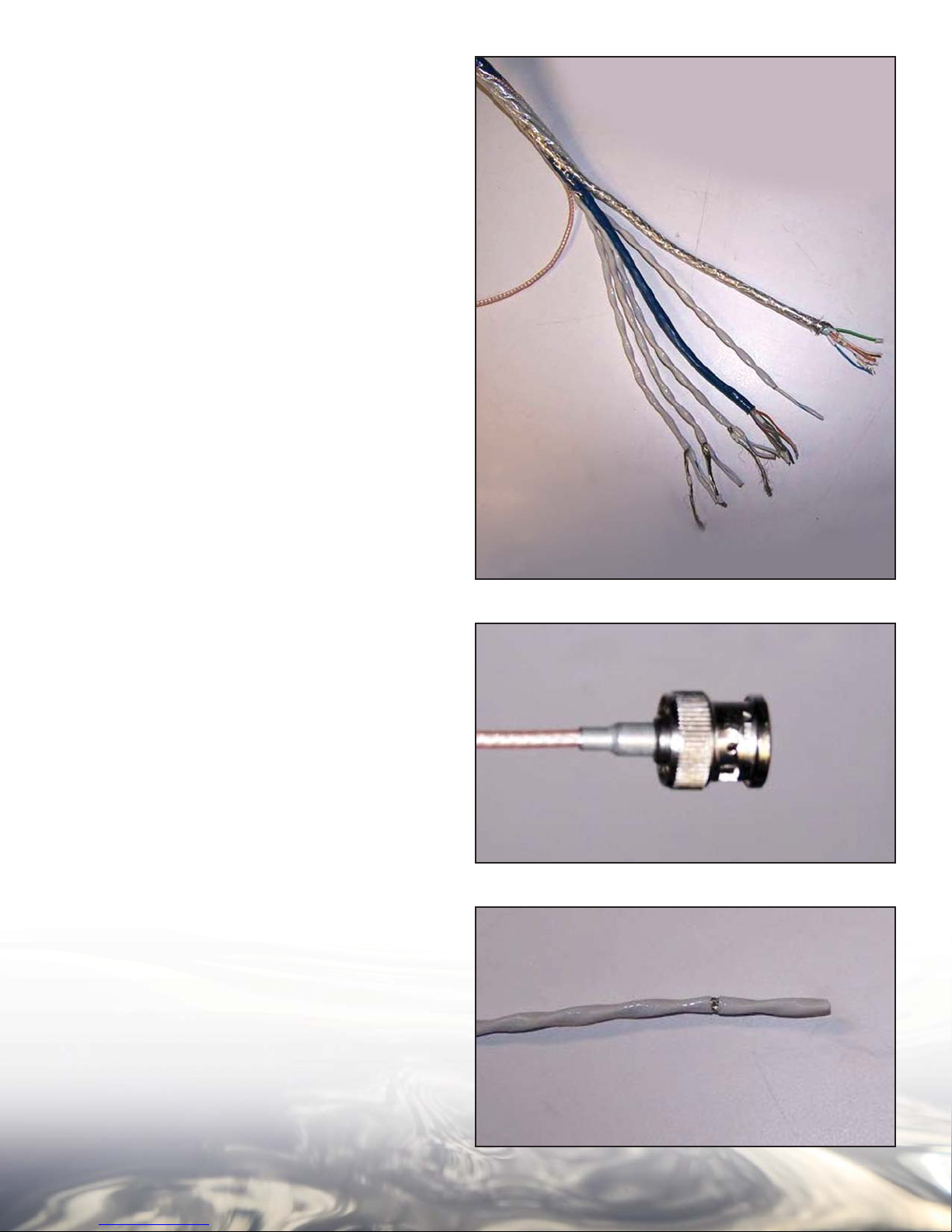
Step 15:
Trim the clear Mylar sheath back so the individual wire bundles can be spread apart
as shown. This will make them easier to
identify and work with.
Cut the blue Ethernet cable to 12.5” long, measured from the end of the cable gland.
Cut the wire bundle inside a clear jacket and
steel braid to measure 11.5” long.
Cut the bundle of 4 twisted pairs inside a white
outer jacket to measure 11.5” long.
The video cable should be cut to 9.5”
Step 16:
Prepare the video cable by securing the crimpable 75-ohm BNC connector (provided) onto
the RG-179 cable.
Step 17:
The rest of the wires will need to be
prepared in a fashion similar to the following
progression.
Carefully cut around the outer insulation as
shown.
10
 Loading...