

Page 1
Instruction Manual
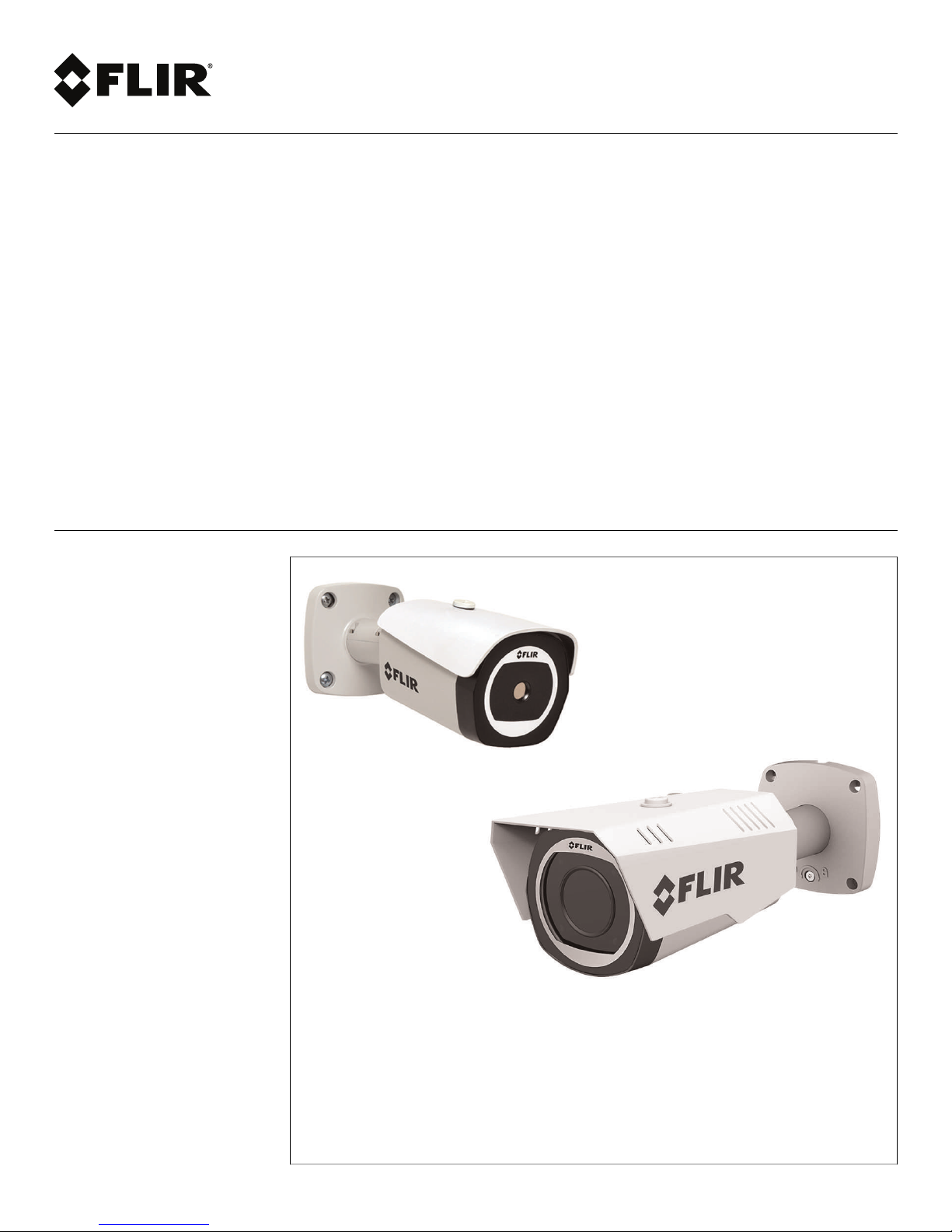
FLIR T43 Series Thermal
Camera
Page 2

Page 3

Instruction Manual
FLIR T43 Series Thermal
Camera
#LX400062; r. 1.0/24298/24299; en-US
iii
Page 4

Page 5

Table of contents
1 Overview ... ................ ................ ....... ................ ................ ....... ........... 1
2 Thermal Imaging Overview . ................ ....... ................ ................ ....... .... 2
3 Tri-Mode IP/MPX/Analog Overview .. ................ ....... ................ ................ 3
4 Web Configuration Setup . ................ ................ ....... ................ .............4
4.1 Supported Browsers....... ....... ................ ................ ....... ......... ...... 4
4.2 Internet Explorer Setup ................ ................ ....... ................ ......... 4
4.3 Safari Setup...... ................ ....... ................ ................ ....... ........... 4
4.4 Firefox Setup ............... ................ ....... ................ ................ ....... 5
4.5 Google Chrome Setup .... ....................................... ................ ...... 6
5 Live View ........... ................ ....... ......... ....... ................ ....... ......... ....... ...8
6 Setup ...... ................ ....... ................ ................ ....... ................ ........... 10
6.1 Camera ............. ....... ................ ................ ....... ................ ....... 10
6.1.1 Settings .. ....... ................ ................ ....... ................ ....... 10
6.1.2 Region of Interest (ROI) .... ....... ................ ....... ......... ....... . 14
6.1.3 Setting ROI to Match Motion Detection Areas .. ................ ..... 15
6.1.4 Video.. ....... ................ ................ ....... ................ ........... 16
6.1.5 Snapshot........... ....... ................ ................ ....... ......... .... 17
6.1.6 Overlay ........... ................ ....... ......... ....... ................ ...... 18
6.1.7 Privacy Masking...... ................ ................ ....... ................ 19
6.1.8 Path ......... ....... ......... ....... ....................................... ..... 20
6.1.9 Audio......... ....... ................ ................ ....... ................ .... 20
6.2 Network..... ................ ................ ....... ......... ....... ................ ...... 21
6.2.1 TCP-IP........... ....................................... ....................... 21
6.2.2 Connection ...... ................ ....... ......... ....... ................ ...... 21
6.2.3 ONVIF ......... ................ ....... ................ ................ ....... .. 22
6.2.4 PPPoE... ................ ................ ....... ......... ....... ............... 23
6.2.5 DDNS. ................ ................ ....... ................ .................. 23
6.2.6 IP Filter ...................................... .................................. 24
6.2.7 SMTP (Email) ................ ....................................... ......... 24
6.2.8 UPnP.. ....... ................ ................ ....... ................ ........... 25
6.2.9 Bonjour ......... ....... ......... ....... ................ ....... ......... ....... . 25
6.2.10 Multicast (Advanced) . ................ ....... ................ .............. 26
6.2.11 QoS (Service Only)...... ....... ................ ................ ....... ..... 27
6.3 Event ...... ....... ................ ....... ......... ....... ................ ....... ......... . 27
6.3.1 Motion Detect....... ................ ....... ................ .................. 27
6.3.2 Relay Activation (Cameras with Alarm I/O Only) ....... ......... .... 29
6.3.3 System Alerts .... ......... ....... ................ ................ ....... ..... 30
6.3.4 Network ........... ................ ....... ................ ................ ..... 34
6.3.5 Illegal Access . ......... ....... ................ ....... ......... ....... ........ 34
6.4 Storage ................ ....... ................ ................ ....... ................ .... 35
6.4.1 Record Schedule ....... ................ ................ ....... ......... .... 35
6.4.2 Snapshot Schedule .. ................ ....... ......... ....... ............... 36
6.4.3 Holiday Schedule ............... ....... ................ ................ ..... 37
6.4.4 Path ......... ....... ......... ....... ....................................... ..... 38
6.4.5 Local ...... ....................................... .............................. 38
6.4.6 FTP............... ....... ................ ................ ....... ................ 38
6.4.7 NAS ...... ................ ................ ....... ......... ....... ............... 39
6.4.8 Record Control .... ................ ....... ......... ....... ................ ... 39
6.5 System ................ ....... ......... ....... ................ ................ ....... ..... 40
6.5.1 General...... ....... ................ ................ ....... ................ .... 40
#LX400062; r. 1.0/24298/24299; en-US
v
Page 6

Table of contents
6.5.2 Date & Time..... ................ ....... ......... ....... ................ ...... 40
6.5.3 Account . ....... ......... ....... ................ ....... ......... ....... ........ 41
6.5.4 Default... ................ ................ ....... ......... ....... ............... 43
6.5.5 Import / Export..... ....................... ................ ................... 43
6.5.6 Auto Maintain ................ ....... ................ ................ ....... .. 44
6.5.7 Upgrade........ ................ ....................... ................ ........ 44
6.6 Information ........... ....... ......... ....... ................ ................ ....... ..... 45
6.6.1 Version ....... ................ ....... ......... ....... ................ .......... 45
6.6.2 Log ........... ....... ................ ................ ....... ................ .... 45
7 Playback (Cameras with microSD only) ....... ................ ................ ....... .. 47
7.1 Playback Controls .. ......... ....... ................ ................ ....... ............ 48
7.2 Backing up Video Files. ................ ................ ....... ................ ....... 49
8 Connecting a Camera in MPX Mode ...... ................ ....... ......... ....... ........ 50
8.1 MPX On-Screen Display (OSD). ................ ................ ....... ............ 50
8.1.1 Accessing the OSD Menu .... ....... ................ ................ ..... 50
8.1.2 OSD Menu Tree .. ................ ................ ....... ................ .... 52
9 Connecting to Cameras with FLIR Cloud™ CMS............ ....... ......... ....... . 53
9.1 System Requirements............... ....... ......... ....... ................ .......... 53
9.2 Installing FLIR Cloud™ Client ....... ................ ....... ......... ....... ........ 53
9.3 Adding a Camera over the Local Network (LAN) ...... ......... ....... ........ 54
9.4 Adding a Camera over the Internet using a DDNS Address .... ....... ..... 55
10 Using FLIR Cloud™ Client for PC or Mac . ....... ......... ....... ................ ...... 58
10.1 Home Page ...... ................ ....... ................ ................ ....... ......... 58
10.2 Live View ...... ....... ......... ....... ................ ................ ....... ............ 58
10.2.1 Live View Controls ......... ....... ......... ....... ................ .......... 59
10.2.2 Opening Live View in Multiple Monitors ................ ............... 60
10.3 Controlling PTZ Cameras . ....... ................ ................ ....... ............ 61
10.3.1 PTZ Presets ......................... ....................................... .. 62
10.3.2 PTZ Tours... ....... ................ ................ ....... ................ .... 63
10.3.3 PTZ Pattern ........... ....................................... ....... ......... 64
10.3.4 PTZ Scan ......... ................ ....................................... ..... 65
10.3.5 PTZ Pan.......... ................ ....... ......... ....... ................ ...... 65
10.4 Playback. ................ ................ ....... ................ ................ ....... .. 65
10.5 Playback Controls .. ......... ....... ................ ................ ....... ............ 67
10.6 Downloading Video to your Computer Hard Drive...... ................ ....... 68
10.7 Alarm ........ ....... ................ ................ ....... ......... ....... ............... 69
10.8 Log..... ................ ....... ......... ....... ................ ................ ....... ..... 70
10.9 E-map ........ ....... ................ ................ ....... ................ .............. 71
10.10 Devices .. ....... ................ ................ ....... ................ ................ .. 73
10.11 Device Config ....... ......... ....... ................ ................ ....... ............ 74
10.12 Alarm CFG .. ....... ................ ................ ....... ................ .............. 74
10.13 Tour & Task .... ....................................... ....... ................ ........... 77
10.14 Account ........... ................ ....... ................ ................ ....... ......... 78
10.14.1 Managing User Accounts....... ....... ......... ....... ................ ... 78
10.14.2 Managing Roles... ................ ....... ......... ....... ................ ... 80
10.15 General ...... ....... ................ ................ ....... ................ .............. 81
10.15.1 Basic.............. ................ ....... ......... ....... ................ ...... 81
10.15.2 File .. ................ ....... ................ ................ ....... ......... .... 81
10.15.3 Alarm Prompt .................................. .............................. 82
10.15.4 Version ........... ....................... ................ ...................... 83
#LX400062; r. 1.0/24298/24299; en-US
vi
Page 7

Table of contents
11 Smartphone and Tablet Apps . ................ ....... ......... ....... ................ ...... 84
11.1 iPhone.... ....... ................ ................ ....... ................ ................ .. 84
11.1.1 Prerequisites............. ....... ................ ................ ....... ...... 84
11.1.2 Connecting to your IP camera on an iPhone ........ ................ . 84
11.1.3 Live View Interface . ....... ......... ....... ................ ....... ......... . 85
11.1.4 Controlling PTZ Cameras. ................ ................ ....... ......... 86
11.1.5 Viewing Snapshots and Videos with Local Files .................... 87
11.1.6 Using Playback Mode on iPhone ........ ....... ................ ........ 87
11.1.7 Enabling Push Notifications ...................... ................ ....... . 89
11.1.8 Using the Event List . ....... ................ ................ ....... ......... 91
11.1.9 Using Favorites.......... ....... ................ ................ ....... ...... 92
11.1.10 Using the E-Map ........ ....... ................ ................ ....... ...... 93
11.1.11 Device Manager.... ................ ....... ................ .................. 95
11.2 iPad ................ ................ ....... ................ ................ ....... ......... 96
11.2.1 Prerequisites............. ....... ................ ................ ....... ...... 96
11.2.2 Connecting to your IP Camera on an iPad.......... ................ .. 97
11.2.3 Live View Interface . ....... ......... ....... ................ ....... ......... . 98
11.2.4 Controlling PTZ Cameras. ................ ................ ....... ......... 98
11.2.5 Using Playback Mode on iPad.............. ................ ....... .... 100
11.2.6 Using Local File to View Manual Recordings .. ....... ............. 101
11.2.7 Enabling Push Notifications ...................... ................ ...... 102
11.2.8 Using the Event List . ....... ................ ................ ....... ....... 104
11.2.9 Using Favorites.......... ....... ................ ................ ....... .... 105
11.2.10 Using the E-Map ........ ....... ................ ................ ....... .... 106
11.2.11 Using the Device Manager ............... ................ ....... ....... 108
11.3 Android ........... ................ ....... ................ ................ ....... ....... 108
11.3.1 Prerequisites............. ....... ................ ................ ....... .... 108
11.3.2 Connecting to your IP camera on Android . ................ ......... 109
11.3.3 Live View Interface . ....... ......... ....... ................ ....... ........ 109
11.3.4 Controlling PTZ Cameras. ................ ................ ....... ....... 110
11.3.5 Viewing Snapshots and Videos with Local Files .................. 111
11.3.6 Using Playback Mode on iPhone ........ ....... ................ ...... 112
11.3.7 Enabling Push Notifications ...................... ................ ...... 113
11.3.8 Using the Event List . ....... ................ ................ ....... ....... 115
11.3.9 Using Favorites.......... ....... ................ ................ ....... .... 116
11.3.10 Using the E-Map ........ ....... ................ ................ ....... .... 117
11.3.11 Device Manager.... ................ ....... ................ ................ 119
12 RTSP Streaming (Advanced). ................ ................ ....... ................ ..... 121
13 Firmware Upgrade Tool ............. ................ ....... ................ ................ 123
13.1 Installing a Firmware Upgrade Over the LAN....... ................ ....... ... 123
13.2 Installing a Firmware Upgrade Over the Internet............... ....... ....... 124
#LX400062; r. 1.0/24298/24299; en-US
vii
Page 8

Page 9
1
Overview
This manual covers the following topics related to your FLIR T43 series thermal camera:
• Web browser configuration interface: See 4 Web Configuration Setup, page 4.
• Firmware upgrade tool: See 13 Firmware Upgrade Tool, page 123.
• Central Management Software for PC / Mac: See 9 Connecting to Cameras with
FLIR Cloud™ CMS, page 53.
• Smartphone / tablet apps: See 11 Smartphone and Tablet Apps, page 84.
NOTE
• For physical installation instructions, please refer to the Quick Connection Guide for your camera
model.
• Some settings described in this manual may not be available depending on the features supported by
your camera model.
#LX400062; r. 1.0/24298/24299; en-US
1
Page 10

2
Thermal Imaging Overview
The Tri-Mode IP/MPX/Analog Thermal camera is a state-of-the-art thermal imaging device
that will provide excellent night visibility and situational awareness without any form of natural or artificial illumination. The sensors do not produce images from visible light like an
ordinary camera or the human eye does. Thermal cameras use energy in the infrared
band to produce images by sensing subtle differences in temperature and generating images based on those differences.
By using a thermal camera, you are viewing heat, not light. If there is a person in the live
view image, you can see there is a person, but identifying who that person is may be impossible regardless of the resolution of your thermal sensor. Similarly, while a higher resolution sensor will detect a person at a greater distance, a low resolution sensor in many
cases will still detect the same motion.
The thermal imaging sensor relies on the fact that all objects, even very cold objects like
ice, emit thermal energy in the portion of the spectrum that the sensor can detect, the long
wave infrared (LWIR). Therefore, unlike a visible-light camera, the thermal imaging sensor
produces images based on directly radiated rather than reflected energy.
Any scene displayed by the sensor contains a range of thermal energy (temperatures),
from the lowest to the highest, that is present in the scene. These temperatures are
grouped by the sensor into a maximum of 256 “shades of gray” based on the thermal image processing settings. Since the T43 Series camera is sensitive enough to distinguish
many more than 256 different temperatures, each “shade of gray” will represent a range of
temperatures.
For example, in a simplistic case, an image comprised of 60% sky (very cold) will devote
60% of the available “shades of gray” to the sky, leaving only 40% for the remainder of the
image. The temperature range assigned to each “shade of gray” is controlled by the
choices in the Camera Settings menu or the MPX on-screen display (OSD).
FLIR Systems, Inc. offers a comprehensive selection of training courses to help you to get
the best performance and value from your T43 Series cameras. You can find out more at
www.flir.com/training.
#LX400062; r. 1.0/24298/24299; en-US
2
Page 11
3
Tri-Mode IP/MPX/Analog
Overview
The cameras offer three video output modes: standard analog, high definition (MPX), and
IP.
• IP / PoE: Provides high definition video output through Ethernet. If you are not using
PoE, make sure to connect the camera to a power source.
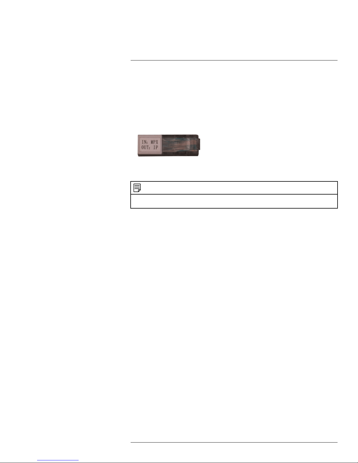
• MPX: Provides high definition video output through a BNC connector. To use MPX
mode, insert the MPX terminator into the camera’s Ethernet cable before you power on
the camera. When the terminator is installed, IP / PoE mode is not available. If the camera is powered up without the terminator installed, IP and analog mode is enabled.
MPX terminator
• Analog: Provides high definition video output through a BNC connector.
NOTE
After the camera is powered on, it may take up to 2 minutes for the camera to fully boot up and show a
picture.
#LX400062; r. 1.0/24298/24299; en-US
3
Page 12
4
Web Configuration Setup
The camera includes a built-in web interface that can be accessed using a web browser.
4.1 Supported Browsers
• Google Chrome™, Mozilla Firefox®, and Apple Safari® (via Webplugin)
• Microsoft Internet Explorer® 8.0 or later, 32-bit version (via ActiveX®)
4.2 Internet Explorer Setup
1. Open Internet Explorer® and enter the camera’s IP address in the address bar in the
following format: http://IP address:HTTP Port.
• For example: http://192.168.0.100:80
• The IP address can be found using the FLIR Cloud CMS. See 9.3 Adding a Camera
over the Local Network (LAN), page 54 for details.
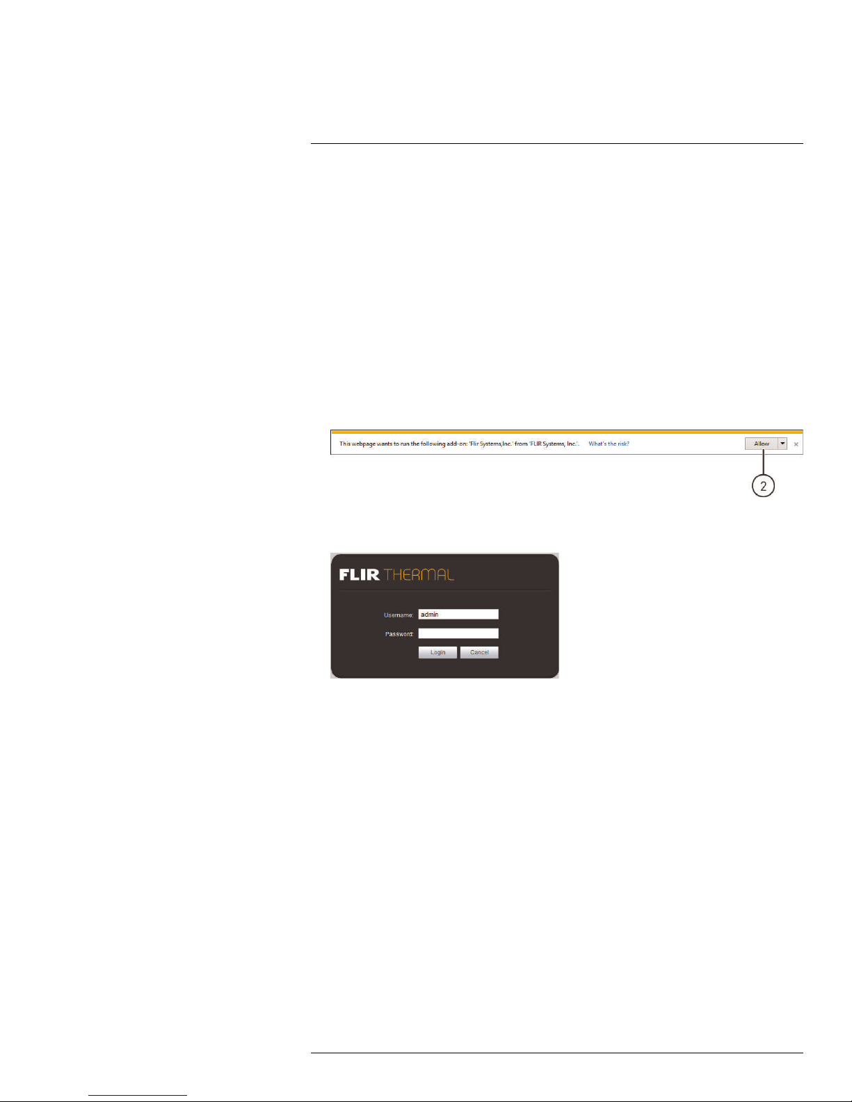
2. A notification bar appears asking if you would like to install ActiveX® plugins. Click In-
stall or Allow to install the plugins.
3. Enter the camera user name (default: admin) and password (default: admin) and click
Login.
4.3 Safari Setup
1. Open Safari® and enter the camera’s IP address in the address bar in the following
format: http://IP address:HTTP Port.
• For example: http://192.168.0.100:80
• The IP address can be found using the FLIR Cloud CMS. See 9.3 Adding a Camera
over the Local Network (LAN), page 54 for details.
#LX400062; r. 1.0/24298/24299; en-US
4
Page 13
4
Web Configuration Setup
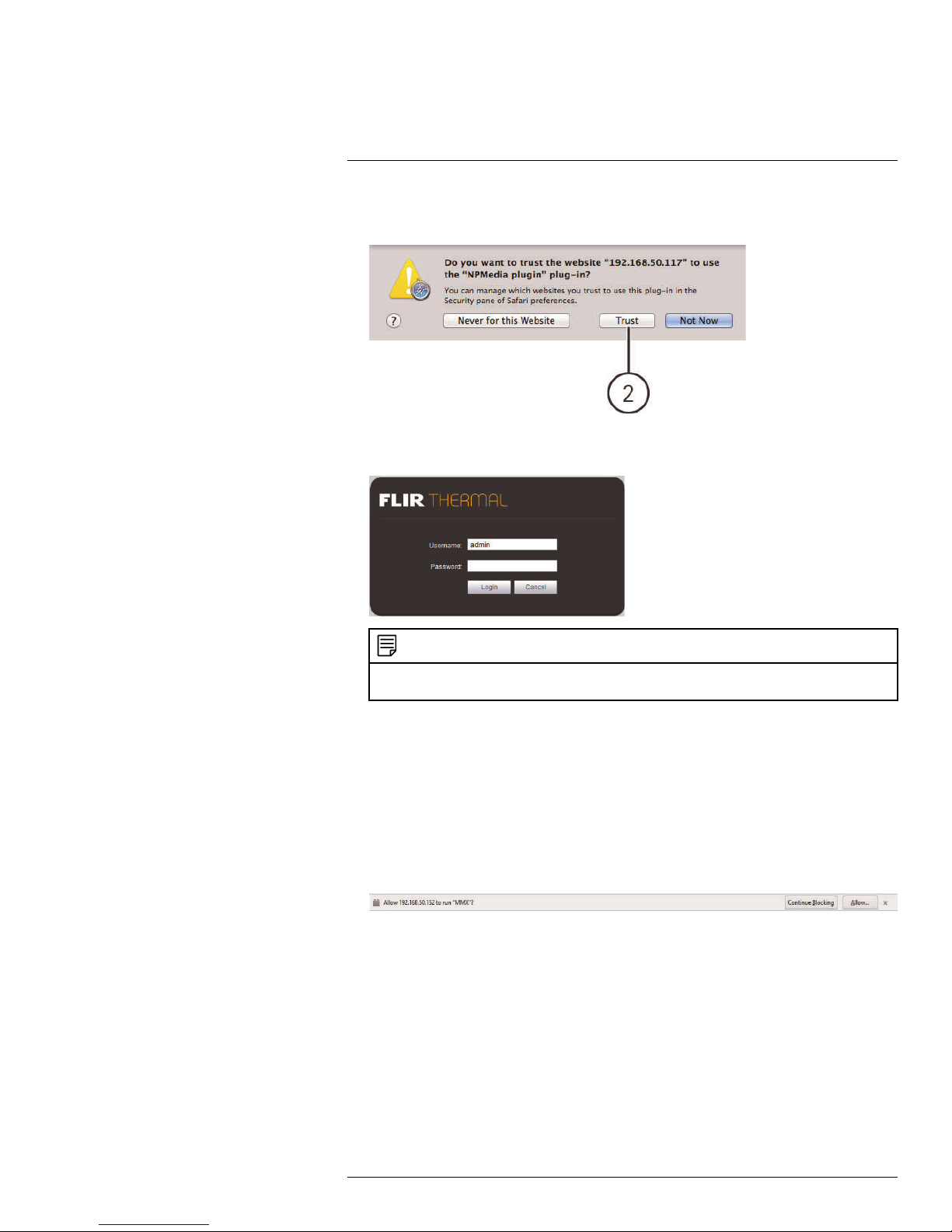
2. A notification appears asking if you want to use the NPMedia plug-in. Click Trust to
use the plug-in.
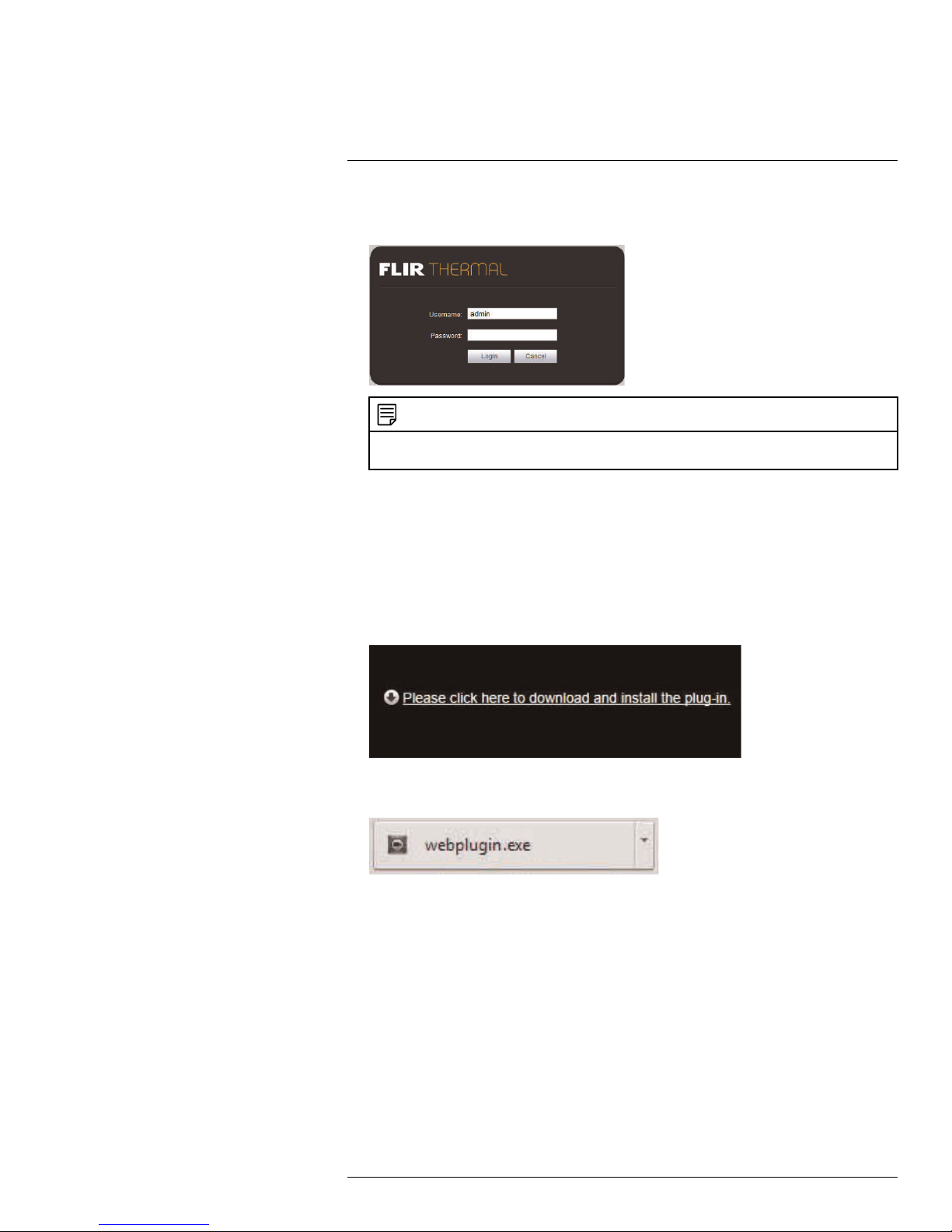
3. Enter the camera user name (default: admin) and password (default: admin) and click
Login.
NOTE
If video from the camera does not appear after installation, quit Safari® by right-clicking on the Safari® icon in the dock and then selecting Quit. Then restart Safari® and log back into your camera.
4.4 Firefox Setup
1. Open Firefox® and enter the camera’s IP address in the address bar in the following
format: http://IP address:HTTP Port.
• For example: http://192.168.0.100:80
• The IP address can be found using the FLIR Cloud CMS. See 9.3 Adding a Camera
over the Local Network (LAN), page 54 for details.
2. A notification appears asking if you want to use the MMX plug-in. Click Allow... to use
the plug-in.
#LX400062; r. 1.0/24298/24299; en-US
5
Page 14
4
Web Configuration Setup
3. Enter the camera user name (default: admin) and password (default: admin) and click
Login.
NOTE
If video from the camera does not appear after installation, quit Firefox® by closing the browser window. Then restart Firefox® and log back into your camera.
4.5 Google Chrome Setup
1. Open Chrome™ and enter the camera’s IP address in the address bar in the following
format: http://IP address:HTTP Port.
• For example: http://192.168.0.100:80
• The IP address can be found using the FLIR Cloud CMS. See 9.3 Adding a Camera
over the Local Network (LAN), page 54 for details.
2. Click Please click here to download and install the plug-in.
3. The plug-in downloads automatically. When finished, double-click the plug-in in the
downloads bar at the bottom of the browser window.
#LX400062; r. 1.0/24298/24299; en-US
6
Page 15
4
Web Configuration Setup
4. Enter the camera user name (default: admin) and password (default: admin) and click
Login.
NOTE
If video from the camera does not appear after installation, quit Chrome™ by closing the browser
window. Then restart Chrome™ and log back into your camera.
#LX400062; r. 1.0/24298/24299; en-US
7
Page 16
5
Live View
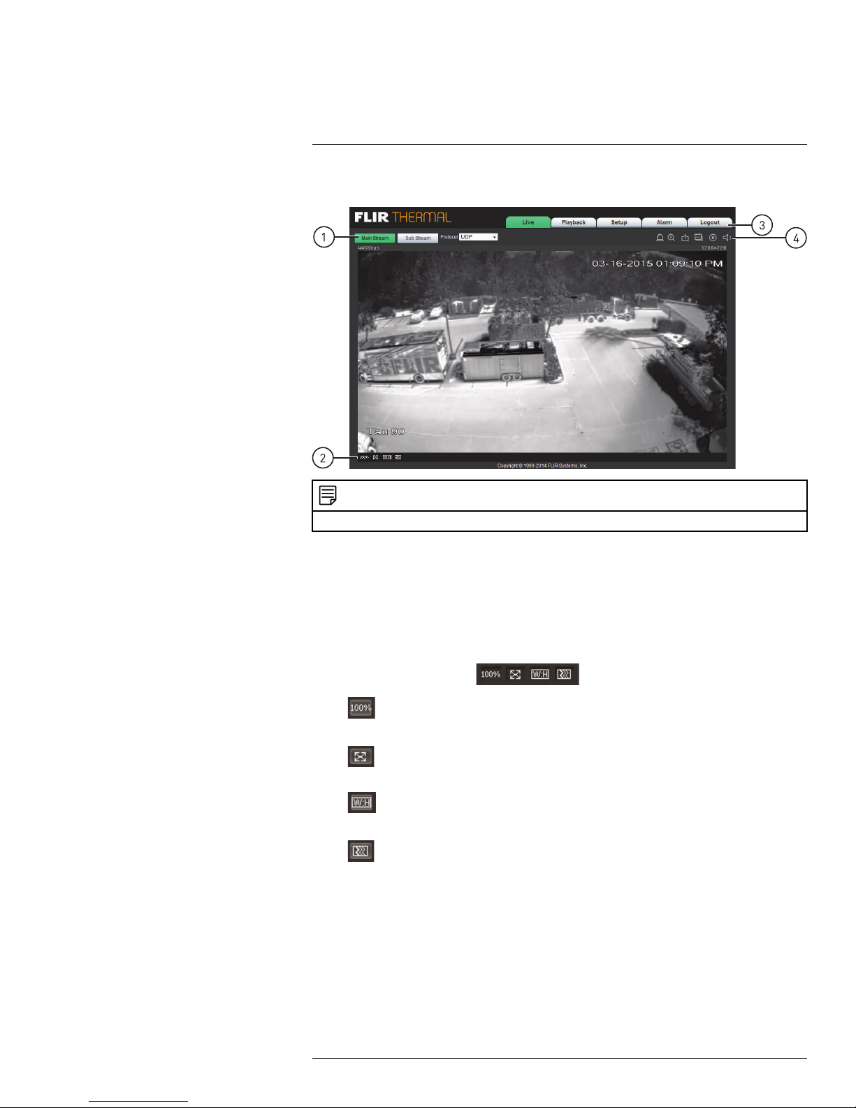
Upon login, the web interface opens to the Live View.
NOTE
Some functions are not available on all IP camera models, based on the features available.
1. Stream/Protocol Select: Allows you to select the video stream and protocol used in
Live View.
• Main Stream: Click to view the Main Stream. The Main Stream provides better pic-
ture quality and resolution, but requires higher bandwidth.
• Sub Stream: Click to view the Sub Stream. The Sub Stream is recommended for
better performance when viewing the camera over the Internet.
• Protocol: Select the protocol that will be used to stream video: TCP or UDP.
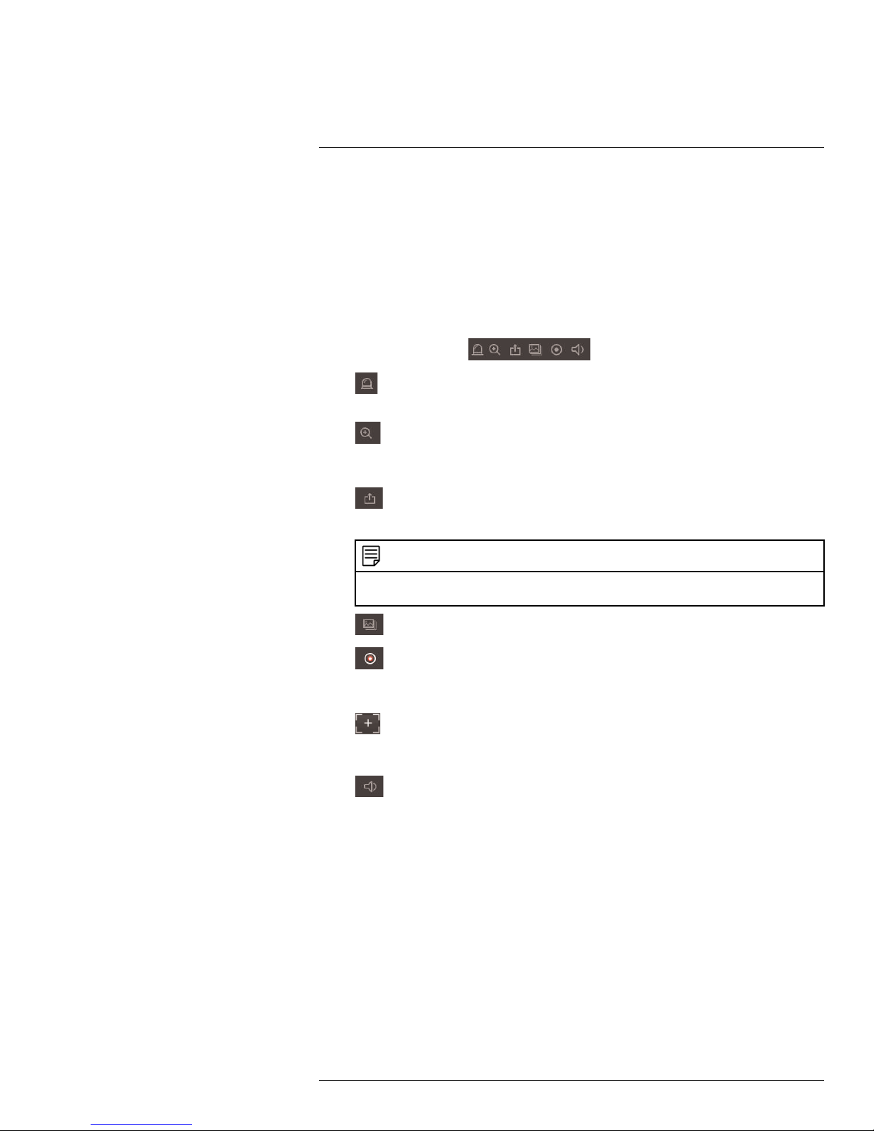
2. Video Display Controls (
•
•
•
•
Original Size: Click to view the video in its original size. This depends on the
resolution and if you are viewing the Main Stream or Sub Stream.
Full Screen: Click to view the video in full screen. Double-click or press ESC
to exit full screen mode.
Width / Height Ratio: Click to select Original to use the original proportions
of the image or Adaptive to adapt the image proportions to the size of the screen.
Realtime / Fluency: Click to select Realtime, Normal, or Fluency.
)
#LX400062; r. 1.0/24298/24299; en-US
8
Page 17
5
Live View
3. Menu Tabs
• Live: Click to access Live View.
• PTZ: On micro PT cameras, the PTZ Control Panel is opened using the PTZ tab,
which replaces the button on the Video Display Controls panel.
• Playback: Click to playback video from the camera’s microSD card (cameras that
support microSD only).
• Setup: Click to setup camera functions.
• Alarm: Click to configure alarms.
• Logout: Log out of the camera.
4. Live View Functions (
•
Alarm Output: Click to activate an alarm output device connected to the cam-
)
era (cameras with alarm I/O only).
•
Digital Zoom: Click to activate digital zoom mode. Click-and-drag in the video
area to select an area to zoom to, then drag to move the zoomed area or follow motion in the video. Right-click to return to full frame view.
•
Snapshot: Click to save a snapshot from the camera to your computer hard
drive. To configure the folder where snapshots are saved, see 6.1.8 Path, page 20.
NOTE
Depending on your computer’s security settings, you may need to run your browser as administrator to save snapshots or manual recordings.
• Triple Snapshot: Save the next three frames from the camera as snapshots.
•
Manual Record: Click to start manually recording live video to your computer
hard drive. Click again to stop recording. To configure the folder where manual recordings are saved, see 6.1.8 Path, page 20.
•
Manual Focus (motorized lens cameras only): Click to display the AF Peak
and AF Max parameters for auto focus. The closer AF Peak and AF Max are, the
better the focus effect is.
•
Audio Output: Click to mute / un-mute audio coming from the camera (audioenabled cameras only; must have self-powered microphone connected to the
camera).
#LX400062; r. 1.0/24298/24299; en-US
9
Page 18

6
Setup
The Setup menus allows you to configure camera settings.
6.1 Camera
The Camera tab allows you to set the camera’s thermal image processing (Settings), the
video stream parameters (Video), and the audio settings for a camera with a microphone
(Audio).
NOTE
For the T43 Series Mini Bullet cameras, the only camera setting available is the region of interest (ROI).
See 6.1.2 Region of Interest (ROI), page 14 for more information.
6.1.1 Settings
The Settings menu allows you to configure the image sensor settings for the camera. As
you make adjustments, the effects will be shown in the video display.
#LX400062; r. 1.0/24298/24299; en-US
10
Page 19
6
Setup
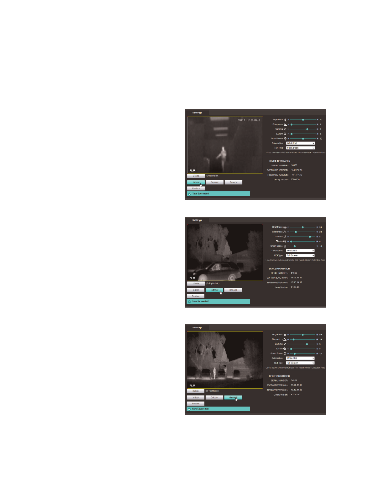
To configure the thermal image profile:
1. Click Indoor, Outdoor, or General (called Default if the camera is in MPX mode) to
change the camera image profile.
Indoor (Sharpness = 0, Gamma = 3, Smart Scene = 50%)
Outdoor (Sharpness = 20, Gamma = 5, Smart Scene = 15%)
General (Sharpness = 10, Gamma = 3, Smart Scene = 15%)
2. If needed, you can make fine-tune adjustments using the Sharpness (DDE), Gamma
(ACE), and Smart Scene Optimization (SSO) settings. Select Restore to set all values
back to their default settings.
#LX400062; r. 1.0/24298/24299; en-US
11
Page 20
6
Setup
NOTE
Preset mode settings are highly subjective and vary considerably depending upon scene content and
viewing or recording preferences. Individual settings may be optimized for each your particular environment. For more information, technical details, or background theory regarding these settings, visit
www.flir.com/.
To configure thermal image settings:
1. Under Brightness (also known as ITT Mean, ITT Offset, or ITT Midpoint), select a value from 0 – 100. This setting determines the temperature that is at the middle of the
256 “shades of gray” available to the camera. Higher values allow more detail in hotter
scenes, while lower values allow more detail in lower temperature scenes.
2. Under Sharpness (also known as Digital Data Enhancement), select a sharpness value. Sharpness is used to enhance image details and/or suppress fixed pattern noise.
Higher values increase Sharpness, while lower values soften (blur) the image and filter
fixed pattern noise.
3. Under Gamma (also known as Active Contrast Enhancement), select a Gamma value.
Gamma provides a contrast adjustment dependent on the relative scene temperature.
Gamma values greater than 0 give more contrast to the hotter scene content and decrease contrast for the colder scene content. Gamma values less than 0 do the opposite by decreasing the contrast for hotter scene content and leaving more of the
“shades of gray” to represent the colder scene content.
4. Under EZoom, select the digital zoom factor. Digital zoom factor is continuously variable; 16 steps for 320-pixel cameras and 24 steps for 480-pixel or 640-pixel cameras.
The zoom factor is stored so that at power-up the last saved field of view is maintained.
5. Under Smart Scene, select a Smart Scene Optimization (SSO) value. This value defines the percentage of the scene that will be allotted a linear mapping. With SSO enabled, the difference in gray shades between two objects is more representative of the
difference in temperature, although the optimization in local contrast can be lost.
#LX400062; r. 1.0/24298/24299; en-US
12
Page 21

6
Setup
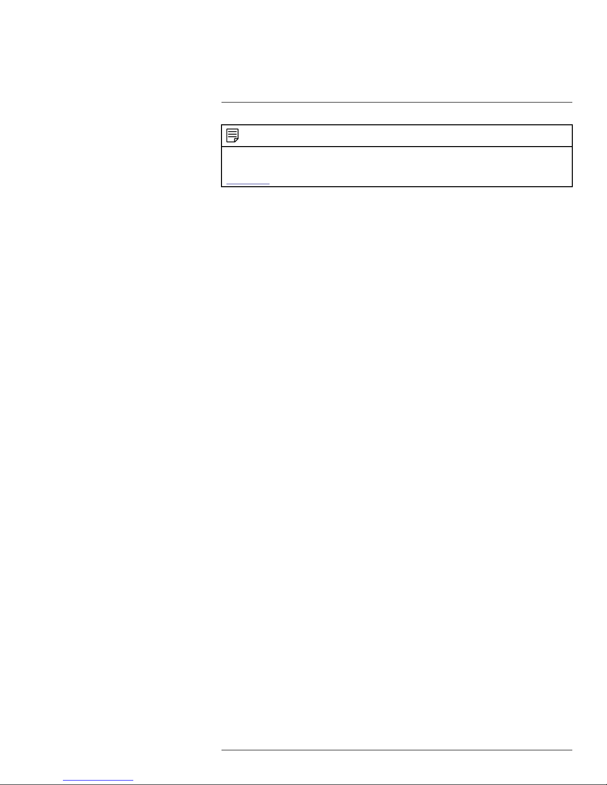
6. Under Colorization, select one of the following colorization palettes. The thermal camera image usually contains 256 “shades of gray” representing different temperatures
present in a scene. The colorization palettes provide the ability to add color to the camera image through the use of Look Up Tables (LUT) that map the 256 temperature
groupings to colors.
• Select the White Hot palette to make hot objects appear “white” or brighter than
colder objects.
• Select the Black Hot palette to make hot objects appear “black” or darker than
colder objects.
• Select Ironbow2 palette ranges from blue (coldest) through red, orange, and white
(hottest).
#LX400062; r. 1.0/24298/24299; en-US
13
Page 22
6
Setup
• Select the IceFire palette to use the same palette as the White Hot palette except
coldest temperatures are blue and the hottest temperatures are red.
6.1.2 Region of Interest (ROI)
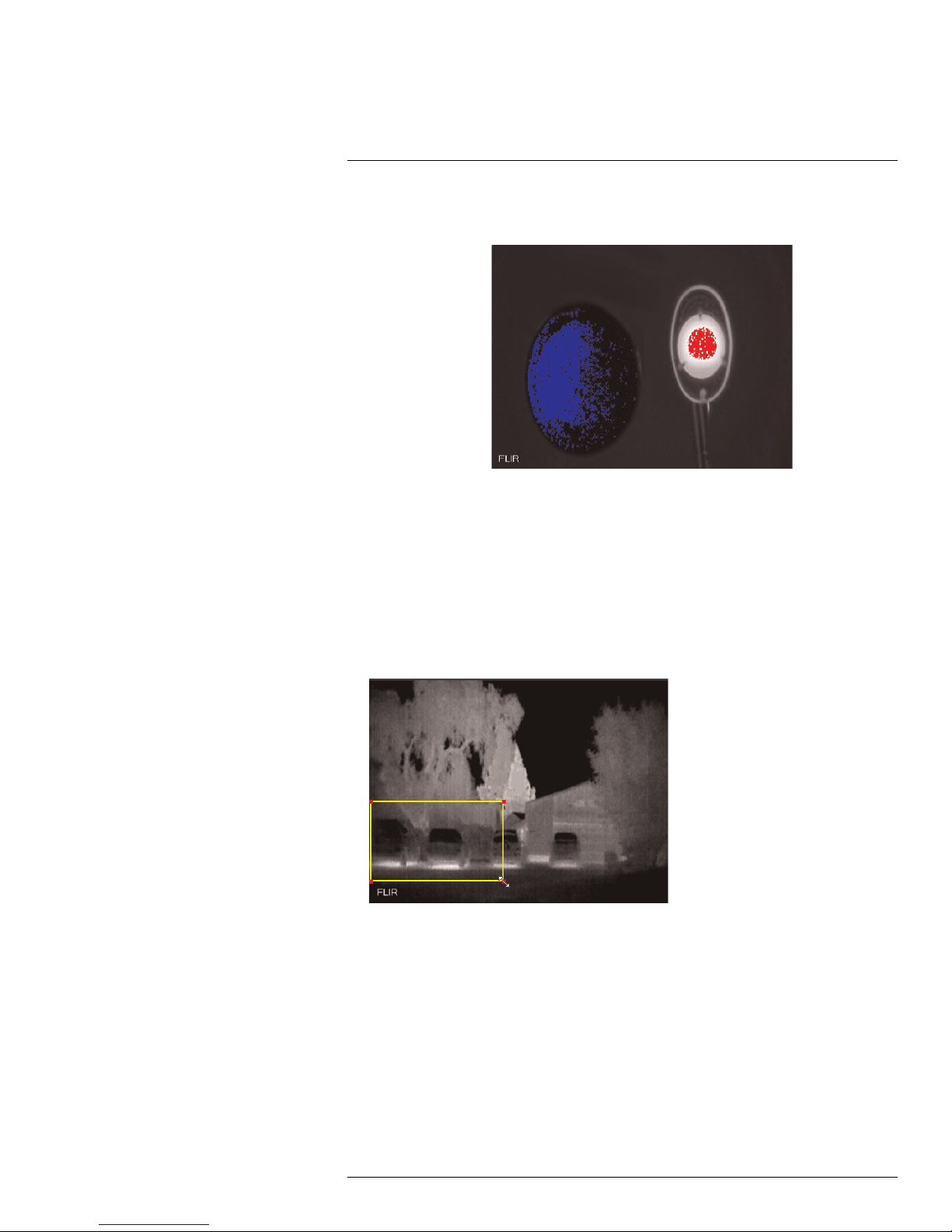
Use the thermal region of interest (ROI) to select only the portion of the scene that the automatic gain control (AGC) will use to optimize the image. The region is automatically adjusted for zoom. You can select a preset ROI or create a custom ROI. The custom ROI
Type provides the ability to setup a rectangular region of any size and move it to any location in the image.
To set up a custom ROI region:
1. Under ROI Type, select Custom.
2. Click and drag a corner of the yellow box to resize the ROI region.
#LX400062; r. 1.0/24298/24299; en-US
14
Page 23
6
Setup
3. Click and drag the box to adjust the location of the ROI region.
6.1.3 Setting ROI to Match Motion Detection Areas
After configuring motion detection areas, you can set up the ROI to include all motion detection areas.
To set ROI to match motion detection areas:
1. Set up motion detection areas. For more details, see 6.3.1 Motion Detect, page 27.
#LX400062; r. 1.0/24298/24299; en-US
15
Page 24
6
Setup
2. Click Camera>Settings to display the camera settings menu.
3. Under ROI Type, select Custom. ROI will automatically be set to include all motion
areas.
Multiple motion detection areas will result in a single ROI.
6.1.4 Video
The Video tab allows you to configure the encoding settings for the camera. Video settings
are divided into Main Stream and Sub Stream.
#LX400062; r. 1.0/24298/24299; en-US
16
Page 25
6
Setup
To configure video quality settings:
1. Check Enable under Sub Stream to enable the sub stream or uncheck to disable.
2. For the Main Stream and Sub Stream, configure the following:
• Code Stream Type: For the Main Stream, select Continuous to configure settings
when motion is not detected, Motion to configure settings when motion is detected,
or Alarm to configure settings when an alarm is detected.
• Encode Mode: Select the encoding type: H.264 (Main H.264 profile), H.264H
(High Profile H.264), H.264B (Baseline H.264 profile), MJPEG.
NOTE
A much higher bitrate and faster connection is required to maintain image quality using MJPEG. It
is recommended to use H.264 unless you have special requirements.
• Resolution: Select the desired resolution for the video stream. There is a different
recommended bit rate depending on the resolution selected.
• Frame Rate (FPS): Select the desired frame rate for the video stream between 1
and 30 FPS.
• Bit Rate Type: Select CBR (Constant Bit Rate) or VBR (Variable Bit Rate). If you
select VBR, you can select the Video Quality between 1 (lowest) and 6 (best).
• Reference Bit Rate: Recommended bit rate range based on the resolution and
frame rate settings you have selected.
• Bit Rate: Select the desired bit rate for each video stream or select Customized
and enter the bit rate in Kbps.
• I Frame: Select the interval for I frames (30~150 for NTSC, 25~150 for PAL).
3. Under Watermark Settings, check to enable watermark to protect against video
tampering.
4. Under Watermark Character, enter the desired watermark text.
5. Click Save to save changes.
6.1.5 Snapshot
The Snapshot menu allows you to configure images quality settings for snapshots.
#LX400062; r. 1.0/24298/24299; en-US
17
Page 26
6
Setup
To configure snapshots:
1. Configure the following:
• Snapshot Type: Select Continuous to configure snapshots taken using scheduled
recording. Select Event to configure snapshots activated by alarms.
• Image Size: The image size of snapshots is the same as the resolution for the
stream selected.
• Quality: Select the image quality for snapshots between 1 (lowest) and 6 (highest).
• Interval: Select the interval between snapshots between 1 and 7 seconds. Select
Customized to select an interval from 1~50000 seconds.
2. Click Save to save changes.
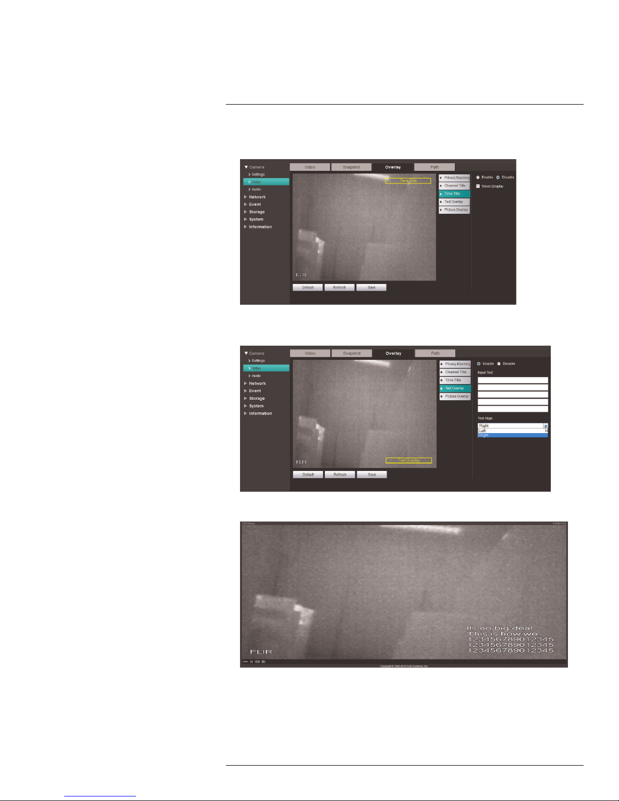
6.1.6 Overlay
The Overlay tab allows you to configure the text and information that appears overtop of
the camera image, such as time and date display. Click Enable or Disable for each of the
sub tabs described below on the Overlay tab.
To configure video overlay:
1. Under Channel Title, click Enable to show the name of the channel on screen. Under
Input channel title, enter a personalized channel name. Click and drag the Channel
Title box to any location on the screen.
#LX400062; r. 1.0/24298/24299; en-US
18
Page 27
6
Setup
2. Under Time Title, click Enable to show the time. Check Week Display to show the
time and day of the week.
3. Under Text Overlay, click Enable to display the Input Text and enter a custom mes-
sage up to 5 lines, 15 characters per line.
4. Click Save to save changes.
Example image of text overlay.
6.1.7 Privacy Masking
Configure privacy masks to hide certain parts of the camera image in video recordings.
#LX400062; r. 1.0/24298/24299; en-US
19
Page 28
6
Setup
CAUTION
Privacy masks block out parts of the camera image entirely and appear as black boxes in recordings.
To configure video overlay:
1. Under Privacy Masking, you can create up to four privacy masks.
• Click the corners of a privacy area to adjust the size of the privacy area.
• Right-click to delete the currently selected privacy area.
• Click-and-drag outside of the privacy areas to create a new privacy area.
• Click Save to save changes.
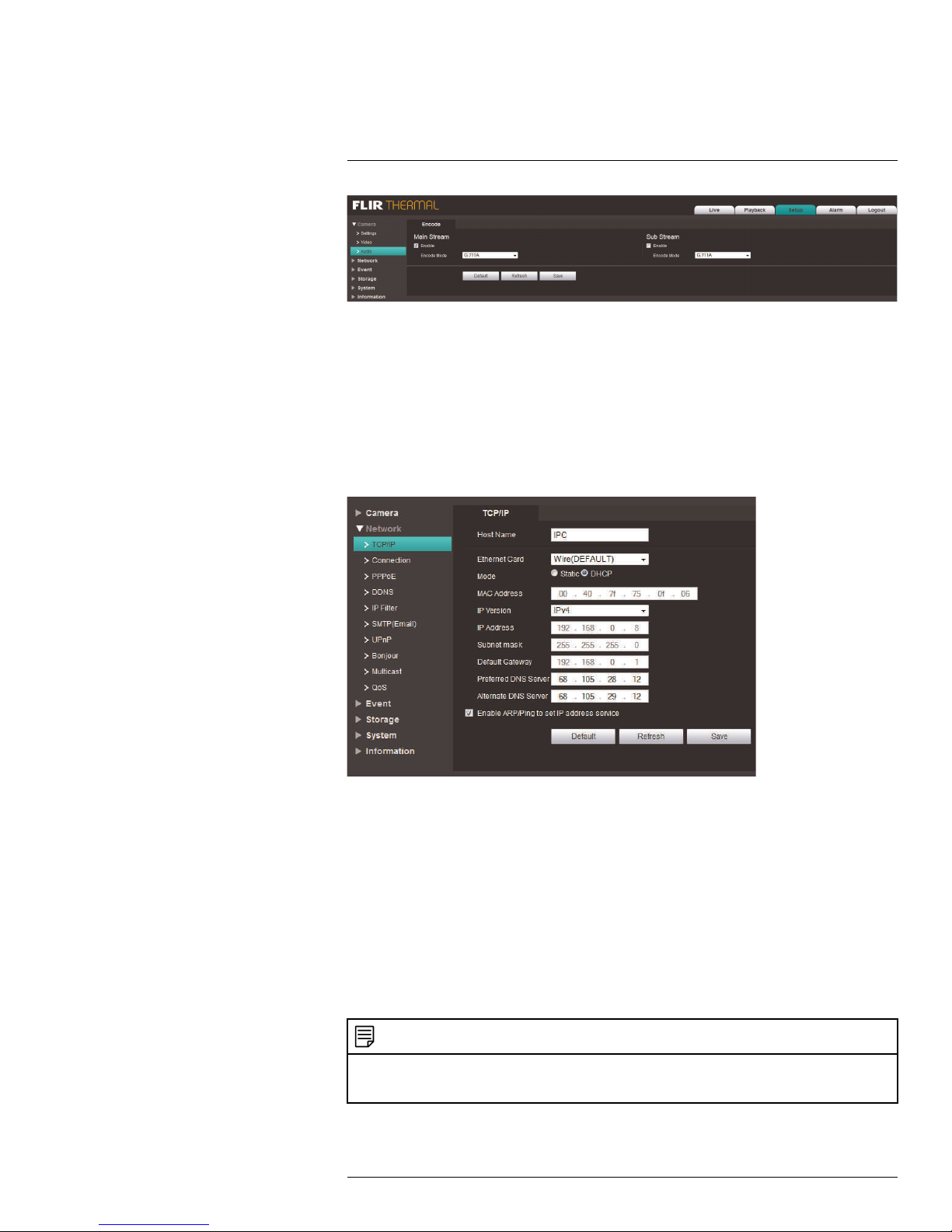
6.1.8 Path
The Path tab allows you to configure the folder where snapshots and manual recordings
are saved to.
To configure the recording and snapshot folder:
1. Configure the following:
• Live Snapshot: The folder on your hard drive where snapshots are stored. Click
Browse to select a different folder.
• Live Record: The folder on your hard drive where manual recordings are stored.
Click Browse to select a different folder.
• Playback Snapshot: The folder on your hard drive where playback snapshots are
stored. Click Browse to select a different folder.
• Playback Download: The folder on your hard drive where playback downloads are
stored. Click Browse to select a different folder.
• Video Clips: The folder on your hard drive where video clips are stored. Click
Browse to select a different folder.
NOTE
An SD / microSD card (not included) must be installed to use playback functions. Check the technical
specifications for your camera to see it supports SD / microSD cards.
2. Click Save to save changes.
6.1.9 Audio
The Audio tab allows you to enable / disable camera audio as well as choose the audio encoding type. The settings in this menu will affect both one-directional and bidirectional
audio for the camera.
NOTE
This setting is only available on cameras with a microphone. Check the technical specifications for your
camera.
#LX400062; r. 1.0/24298/24299; en-US
20
Page 29
6
Setup
To configure audio settings:
1. Check Enable under Main Stream, Sub Stream, or both to enable audio.
2. Under Encode Mode, select an encoding mode from PCM, G.711A and G.711Mu.
3. Click Save to save changes.
6.2 Network
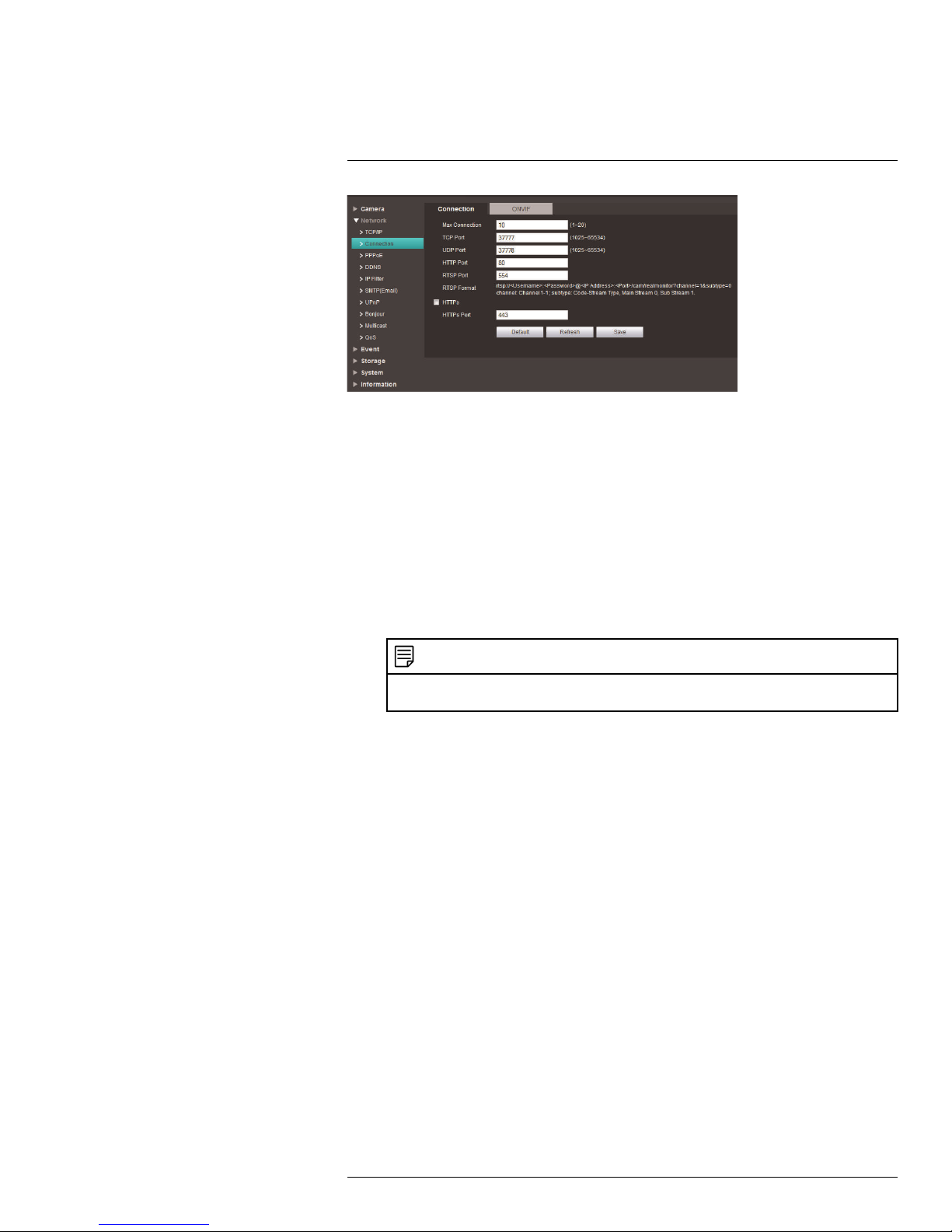
6.2.1 TCP-IP
The TCP-IP menu allows you to configure the camera for DHCP or Static IP addressing.
To configure IP address settings:
1. Under Host Name, enter the Host Name for the camera up to 32 characters.
2. Under IP Version, select IPV4 or IPV6.
3. Under Mode, select Static or DHCP. If you select Static, configure the IP Address,
Subnet, Mask, Default Gateway, Preferred DNS Server, and Alternate DNS
Server.
4. Click Save to save changes.
6.2.2 Connection
The Connection menu allows you to configure the camera ports and maximum connections to the camera. You must port forward the HTTP (default: 80) and TCP (default:
35000) port numbers on your router to enable remote connection to your camera.
NOTE
If you are not using an NVR and are setting up multiple cameras in the same network for remote access,
you must assign unique TCP and HTTP ports for each camera. Two cameras cannot share the same port
number.
#LX400062; r. 1.0/24298/24299; en-US
21
Page 30
6
Setup
To configure connection settings and ports:
1. Under Max Connection, enter the maximum number of devices that can connect to
the camera at the same time between 1 and 20.
2. Configure the following port settings:
• TCP Port: Enter the TCP (Client) Port number (default: 35000). The TCP port is
used to stream video to remote computers or mobile devices. The TCP Port must
be port forwarded to enable remote connection to your camera.
• UDP Port: Enter the UDP Port number (default: 37778). The UDP Port is used for
special applications only.
• HTTP Port: Enter the HTTP Port (default: 80). The HTTP Port is used to access the
camera’s web interface. The HTTP Port must be port forwarded to enable remote
access.
NOTE
If you change the HTTP Port to anything other than 80, you must enter colon (:) and the HTTP
port in your web browser to access the camera (e.g. http://tomsmith.myddns-flir.com:85).
• RTSP Port: Enter the RTSP Port (default: 554). The RTSP Port is used for special
applications. For details on RTSP streaming, see 12 RTSP Streaming (Advanced),
page 121.
3. (Optional) To enable HTTPS, check HTTPs On. To connect to the camera using
HTTPS, you must forward the HTTPS port (default: 443) on your router. You must also
connect to the camera using the following format:
• https://IP or DDNS address:HTTPS Port
• For example: https://tomsmith.myddns-flir.com:443
4. (Optional) To configure the HTTPS port, enter the custom port number under HTTPS
Port (default: 443).
5. Click Save to save changes.
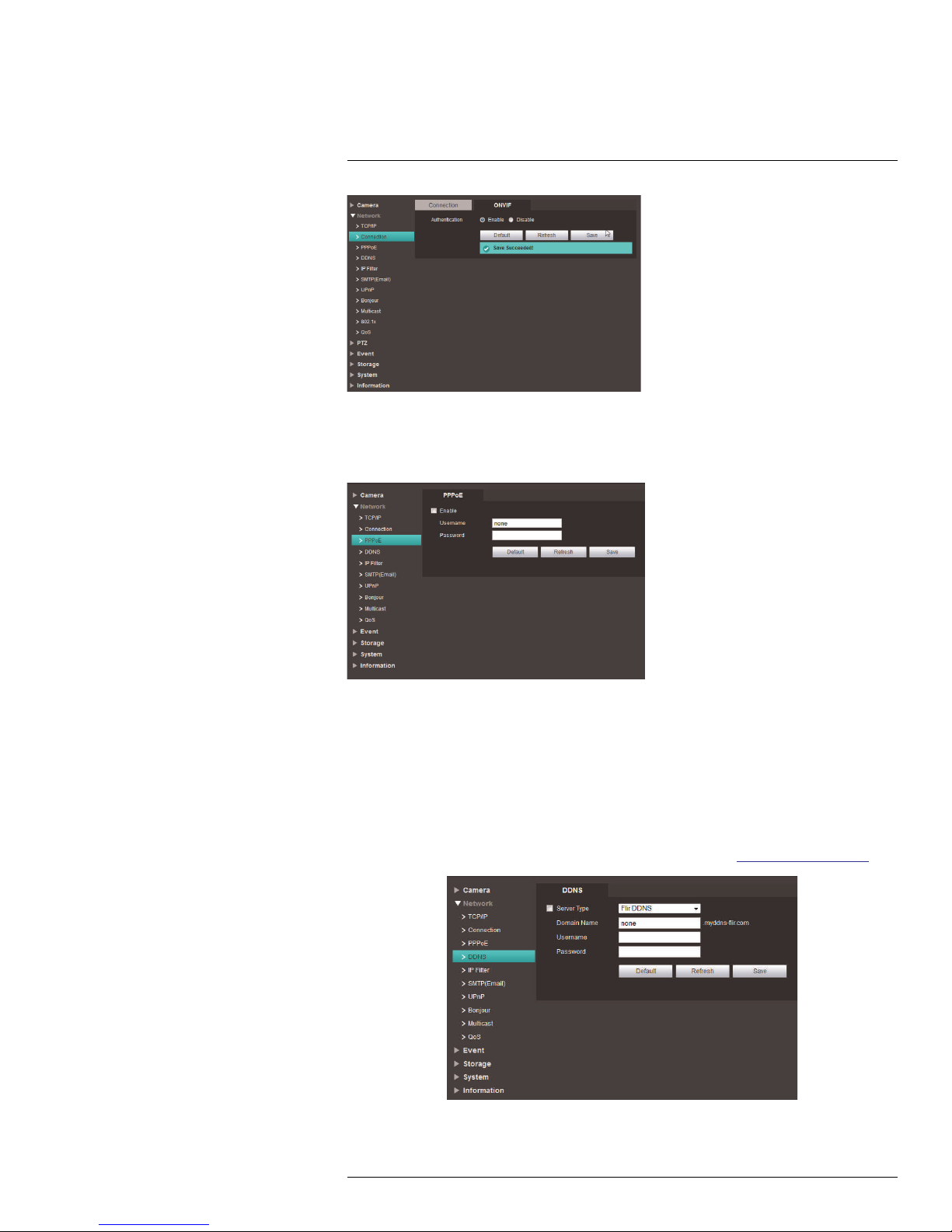
6.2.3 ONVIF
The camera supports ONVIF Profile S v2.4. You can enable or disable ONVIF authentication under Network>Connection>ONVIF.
#LX400062; r. 1.0/24298/24299; en-US
22
Page 31
6
Setup
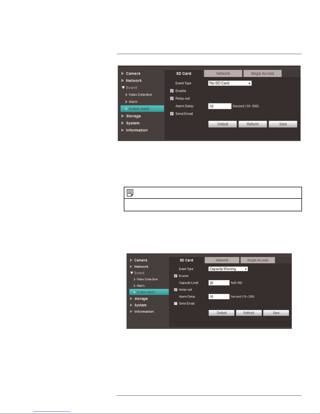
6.2.4 PPPoE
The PPPoE menu allows you to enter a PPPoE user name and password (usually provided
by a DSL provider).
To configure PPPoE:
1. Click Enable.
2. Under Username, enter the PPPoE user name.
3. Under Password, enter the PPPoE password.
4. Click Save to save your changes.
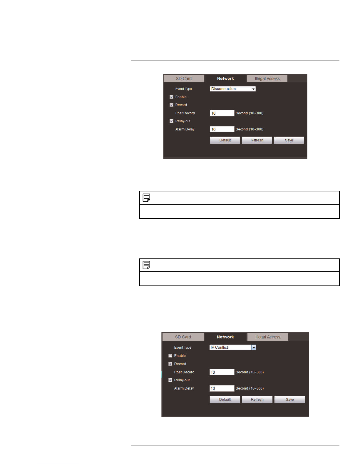
6.2.5 DDNS
The DDNS menu allows you to set up the camera with a free FLIR DDNS account for remote connectivity. You can register for a FLIR DDNS account at ddns.myddns-flir.com.
#LX400062; r. 1.0/24298/24299; en-US
23
Page 32

6
Setup
To configure DDNS:
1. Under Server Type, check the checkbox and select FlirDDNS.
2. Under Domain Name, enter the Domain Name from the confirmation email you received after registering for DDNS.
3. Under Username, enter the User Name from the confirmation email.
4. Under Password, enter the Password from the confirmation email.
5. Click Save.
NOTE
It may take between 10~15 minutes for the DDNS server to update with your new DDNS address.
6.2.6 IP Filter
The IP Filter allows you to create a white list of device MAC or IP addresses that can access the camera. If you use the IP filter menu, devices that are not on the white list will not
be able to remotely connect to the camera.
NOTE
If you enable the IP filter the camera will block any device that is not listed. Make sure the correct devices
are added to the list, or you may not be able to access the camera.
To filter connections based on IP or MAC addresses:
1. Click Add IP/MAC.
2. Select IP Address or MAC Address and then enter the address of the device you
would like to add to the white list.
3. Click Save.
4. Check Trusted Sites.
5. Click Save to save changes.
6.2.7 SMTP (Email)
The SMTP menu allows you to set up email alerts for motion or alarms.
#LX400062; r. 1.0/24298/24299; en-US
24
Page 33

6
Setup
To configure SMTP Settings:
1. Configure the following:
• SMTP Server: Enter the SMTP server address.
• Port: Enter the Port used by the server.
• Anonymity: Check if the server allows anonymous logins or uncheck to enter cre-
dentials to access the server.
• Username: Enter the user name of the sender’s account.
• Password: Enter the password of the sender’s account.
• Sender: Enter the sender’s email account.
• Authentication: Select SSL or TLS.
• Mail Receiver: Enter the email address that will receive email alerts.
• Interval: Select the interval for sending email alerts. The system will only send
email alerts after this interval has passed.
• Health Mail: Check to enable the camera to send health alerts. If you enable health
alerts, enter the interval in seconds under Update Period.
2. Click Email Test to send a test email using the settings you have entered.
3. Click Save to save changes.
6.2.8 UPnP
UPnP allows you to map port numbers between the LAN and the Internet. Depending on
your router version, you may need to disable UPnP function.
6.2.9 Bonjour
The Bonjour menu allows you to enable the Bonjour service to easily detect the camera on
a local network when using a Mac.
#LX400062; r. 1.0/24298/24299; en-US
25
Page 34

6
Setup
To enable / disable the Bonjour service:
1. Check Enable to enable Bonjour or uncheck to disable.
2. Under Server Name, enter the name of the camera that will show up when accessing
the camera through Bonjour in Safari.
3. Click Save to save changes.
To access the camera through Bonjour:
1. In Safari, click
to open the Bookmarks menu.
2. Click Bonjour, the IP Camera will appear in the list.
3. Double-click the IP camera to open it in a browser tab.
6.2.10 Multicast (Advanced)
When there are multiple hosts receiving the same data packets, multicast is the best option to reduce the bandwidth and the CPU load. The source host can send out one data
set.
#LX400062; r. 1.0/24298/24299; en-US
26
Page 35

6
Setup
To enable multicast:
1. Under Main Stream or Sub Stream, click Enable. The main stream and sub stream
cannot be enabled at the same time.
2. Under Multicast Address, enter the desired multicast IP address. For example,
239.255.42.42.
3. Under Port, enter your desired port for main stream, such as 36666 for main stream.
Main and sub stream should have different ports if multicast IP is the same.
Use the following URL to retrieve the video:
• rtsp://<IP Address>/cam/realmonitor?channel=1&subtype=<0 for main stream or 1 for
substream>&unicast=false
For example, if the camera has the IP address 192.168.250.226, and multicast data
as above, use:
• Main Stream:
rtsp://192.168.250.226/cam/realmonitor?channel=1&subtype=0&unicast=false
• Sub Stream:
rtsp://192.168.250.226/cam/realmonitor?channel=1&subtype=1&unicast=false
6.2.11 QoS (Service Only)
6.3 Event
6.3.1 Motion Detect
The Video Detect menu allows you to set up motion detection and recording.
NOTE
Recording functions require an FTP server or an on-board microSD card. Some camera models do not
support these recording features.
To set up motion detection settings:
1. Check Enable to enable motion detection.
#LX400062; r. 1.0/24298/24299; en-US
27
Page 36

6
Setup
2. To configure a schedule when motion detection will be activated, click Setup next to
Working Period.
• Select the day you would like to configure by clicking the Setup buttons. You can
apply the same schedule to multiple days using the checkboxes.
• Configure up to 6 time periods when motion detection will be activated.
• Click Save. Repeat the steps above if you would like to apply a different schedule to
different days.
3. Under Anti-dither, enter the anti-dither time. After a motion event occurs and motion
stops, if motion is detected within the anti-dither time, the system continues the motion
event and includes the new motion within the first event, rather than creating a new
motion event.
#LX400062; r. 1.0/24298/24299; en-US
28
Page 37

6
Setup
4. To configure the motion grid, click Setup next to Area.
• Click squares on the grid to create motion detection areas. Click on the different col-
ors to set 4 different areas.
• To move an area, click inside and drag.
• Right-click to delete the selected area.
• Click-and-drag outside of all areas to draw a new area. You may have up to 4 motion
areas.
• Use the sliders to adjust the Sensitivity and Threshold for motion detection.
CAUTION
It is recommended to have someone moving in areas of interest on the camera image during
setup.
• The Sensitivity determines how sensitive the camera is to motion. For example,
if the sensitivity is high, small amounts of motion will score higher on the graph. It
is recommended to select a Sensitivity between 30~70.
• The Threshold determines how much motion is required to trigger an alarm or
recording. It is represented by the horizontal line on the graph. If the amount of
motion in the area exceeds this line, it will trigger an alert. It is recommended to
select a Threshold between 10~50.
• Each motion area can have a separate Sensitivity and Threshold value.
• Click Save.
5. Check Record to record when motion is detected. microSD or FTP recording must be
configured to use this function.
6. Enter the number of seconds the camera will record after motion is detected under
Post Record.
7. Check Relay Out to trigger an external alarm device when the camera detects motion.
The camera must have an Alarm Output to use this function.
8. Enter the number of seconds before the camera will trigger the external device under
Alarm Delay.
9. Check Send Email for the camera to send an email alert when motion is detected.
Email settings must be configured to receive email alerts.
10. Check Snapshot for the camera to save a snapshot when motion is detected. microSD or FTP recording must be configured to use this function.
11. Click Save to save changes.
6.3.2 Relay Activation (Cameras with Alarm I/O Only)
The Alarm menu allows you to configure settings for alarm devices. Your camera must
have an alarm I/O connector to use alarm devices.
#LX400062; r. 1.0/24298/24299; en-US
29
Page 38

6
Setup
To configure alarm device settings:
1. Configure the following:
• Under Relay-In, select the alarm device you would like to configure.
• Check Enable to enable the selected alarm input device.
• Click Setup next to Working Period to set a schedule for alarm device activation.
• Under Anti-Dither, enter the latch time in seconds.
• Under Sensor Type, select NO (Normally Open) or NC (Normally Closed) depend-
ing on the type of sensor used.
• Check Record to record when a sensor device is triggered.
• Under Post Record, enter the amount of time the system will record when a sensor
device is triggered.
• Check Relay-out to activate an alarm output device (e.g. strobe light) when the
sensor device is triggered. The camera must have an alarm output to use this feature. Enter the number of seconds before the camera will trigger the external device
under Alarm Delay.
• Check Send Email for the camera to send out an alert email when the sensor de-
vice is triggered.
• Check Snapshot for the camera to save a snapshot to FTP or microSD when the
sensor device is triggered.
2. Click Save to save changes.
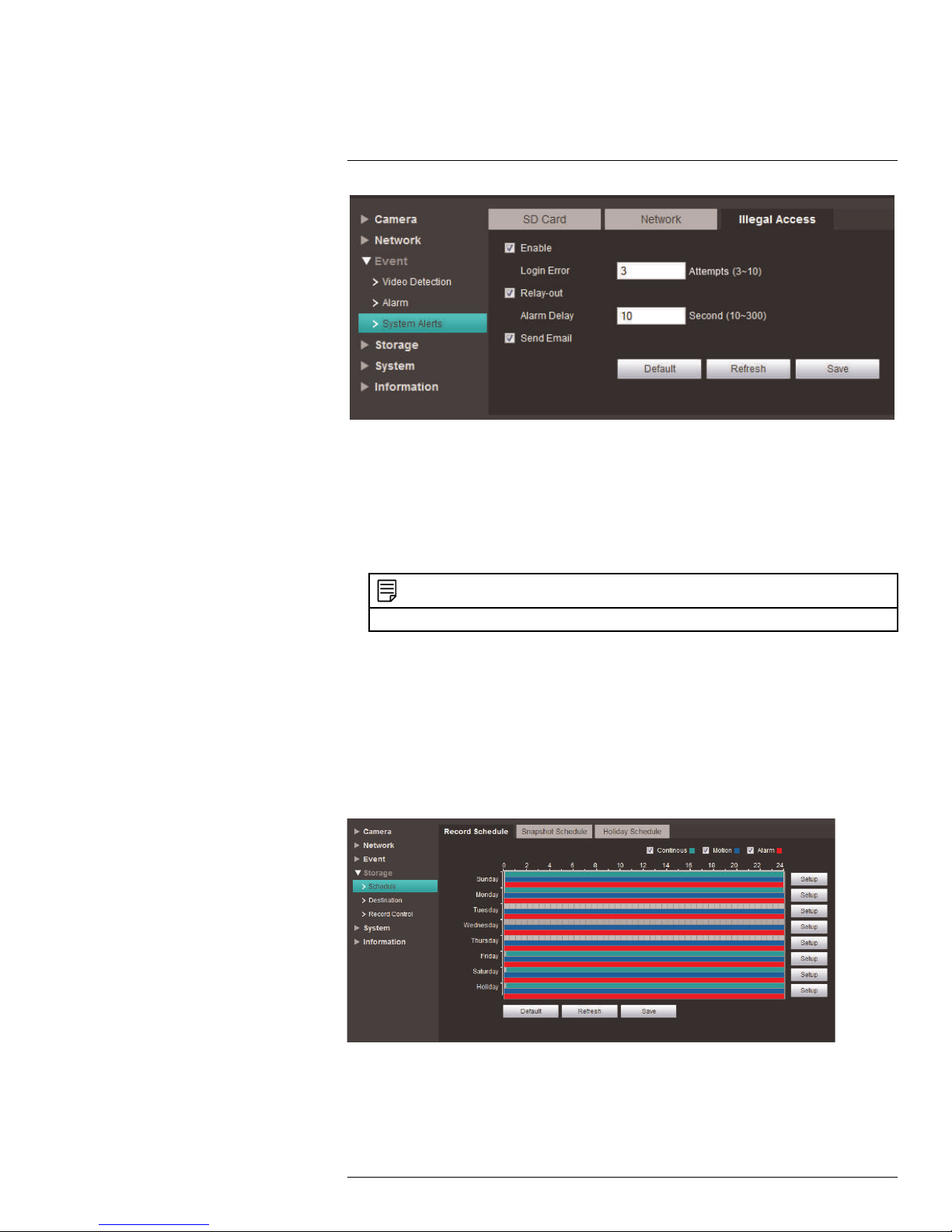
6.3.3 System Alerts
System Alerts include notifications for SD Card, Network, and Illegal Access issues. Each
event can be configured independently.
NOTE
The No SD Card warning is only available on cameras that support SD / microSD cards. Check the technical specifications for your camera.
#LX400062; r. 1.0/24298/24299; en-US
30
Page 39
6
Setup
To configure No SD Card errors:
1. Under Event Type, select No SD Card.
2. Check Enable to enable No SD Card errors.
3. Check Relay-out to trigger an alarm out device when No SD Card errors occur. Under
Alarm Delay, enter the number of seconds before the alarm out device will be
activated.
NOTE
Relay-out is only available if your camera supports alarm output. Check the technical specifications
for your camera.
4. Check Send Email to send an email alert when No SD Card errors occur.
5. Click Save to save changes.
To configure Capacity Warnings:
A Capacity Warning occurs when the recording destination (microSD / SD card or FTP
server) reaches capacity.
To configure Capacity Warnings:
1. Under Event Type, select Capacity Warning.
2. Check Enable to enable Capacity Warnings.
3. Under Capacity Limit, set the percentage of free space on the recording destination
that will trigger a Capacity Warning. For example, if you enter 10% and your microSD
card is 1GB, a warning will occur when there is only 100MB of free space remaining.
#LX400062; r. 1.0/24298/24299; en-US
31
Page 40

6
Setup
4. Check Relay-out to trigger an alarm out device when Capacity Warnings occur. Under
Alarm Delay, enter the number of seconds before the alarm out device will be
activated.
NOTE
Relay-out is only available if your camera supports alarm output. Check the technical specifications
for your camera.
5. Check Send Email to send an email alert when Capacity Warnings occur.
6. Click Save to save changes.
To configure SD Card Errors:
An SD Card Error occurs if an error occurs recording to the SD / microSD card (for example, if the card is damaged or is using the wrong file system).
NOTE
The SD Card Error warning is only available on cameras that support SD / microSD cards. Check the
technical specifications for your camera.
To configure SD Card Errors:
1. Under Event Type, select SD Card Error.
2. Check Enable to enable SD Card Errors.
3. Check Relay-out to trigger an alarm out device when SD Card Errors occur. Under
Alarm Delay, enter the number of seconds before the alarm out device will be
activated.
NOTE
Relay-out is only available if your camera supports alarm output. Check the technical specifications
for your camera.
4. Check Send Email to send an email alert when SD Card Errors occur.
5. Click Save to save changes.
To configure Disconnection errors:
A Disconnection error occurs if the camera is disconnected from the network.
#LX400062; r. 1.0/24298/24299; en-US
32
Page 41
6
Setup
To configure Disconnection Errors:
1. Check Enable to enable Disconnection errors.
2. Check Record to record to the microSD / SD card when Disconnection errors occur.
NOTE
The camera must support microSD / SD card recording to use this function. Check the technical
specifications for your camera.
3. Under Post Record, enter the number of seconds the camera will record after a Disconnection error.
4. Check Relay-out to trigger an alarm out device when Disconnection errors occur.
Under Alarm Delay, enter the number of seconds before the alarm out device will be
activated.
NOTE
Relay-out is only available if your camera supports alarm output. Check the technical specifications
for your camera.
5. Check Send Email to send an email alert when Disconnection errors occur.
6. Click Save to save changes.
To configure IP Conflict errors:
An IP Conflict error occurs if another device is assigned the same IP address as the IP
camera.
#LX400062; r. 1.0/24298/24299; en-US
33
Page 42
6
Setup
To configure IP Conflict errors:
1. Under Event Type, select IP Conflict.
2. Check Enable to enable IP Conflict errors.
3. Check Record to record to the microSD / SD card when IP Conflict errors occur.
NOTE
The camera must support microSD / SD card recording to use this function. Check the technical
specifications for your camera.
4. Under Post Record, enter the number of seconds the camera will record after an IP
Conflict
5. Check Relay-out to trigger an alarm out device when IP Conflict errors occur. Under
Alarm Delay, enter the number of seconds before the alarm out device will be
activated.
NOTE
Relay-out is only available if your camera supports alarm output. Check the technical specifications
for your camera.
6. Check Send Email to send an email alert when IP Conflict errors occur.
7. Click Save to save changes.
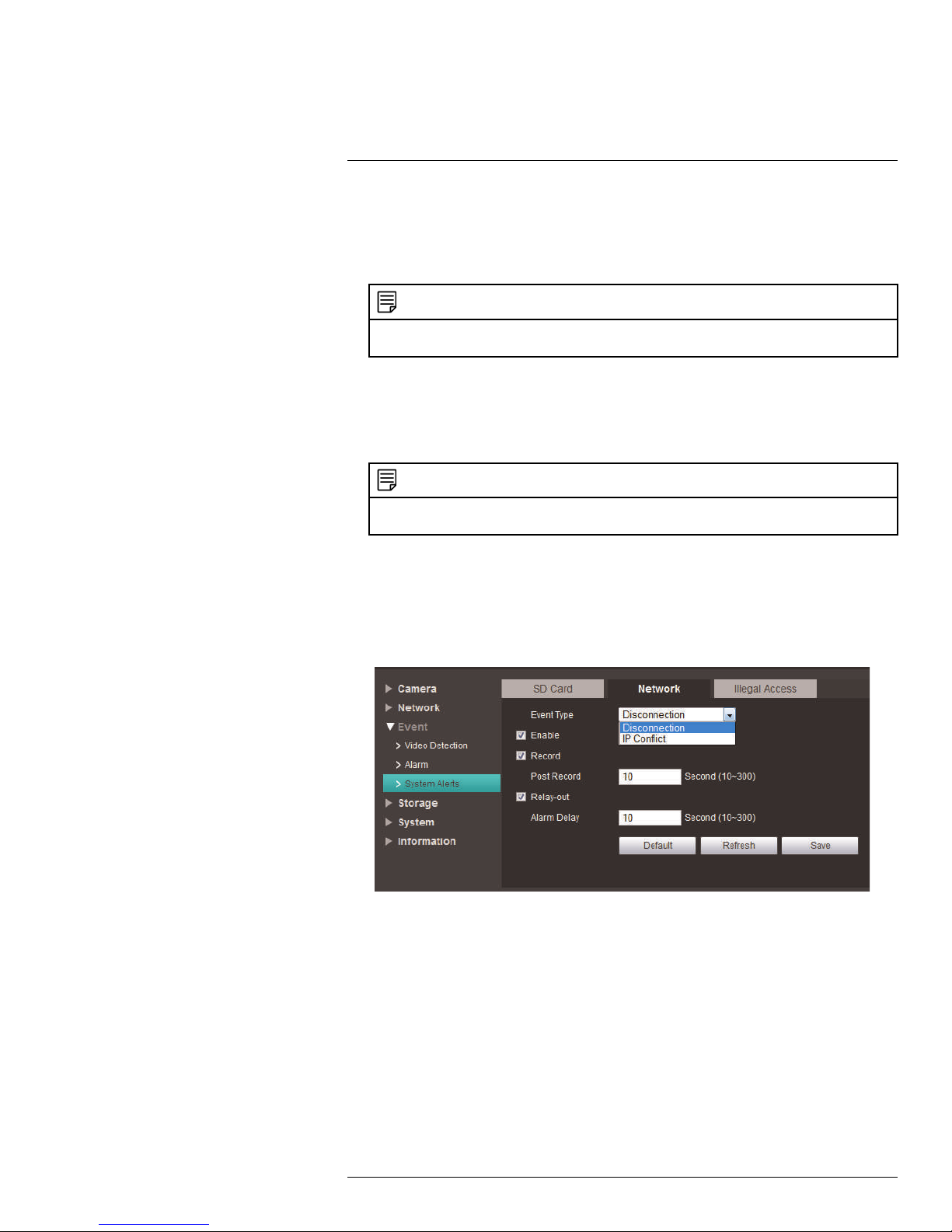
6.3.4 Network
Some cameras group the IP Conflict and Disconnection warnings into a single Network
warning tab.
To enable IP Conflict / Disconnection errors:
1. Under Event Type, select Disconnection or IP Conflict.
2. Check Enable to enable the selected warning type.
6.3.5 Illegal Access
Set the camera to trigger an alarm (if supported) or send an email when the username or
password is incorrectly entered multiple times to access the camera.
#LX400062; r. 1.0/24298/24299; en-US
34
Page 43
6
Setup
To enable Illegal Access errors:
1. Check Enable to enable the Illegal Access warning.
2. Under Login Error, enter the number of times that wrong username / password can
be entered before the warning is triggered.
3. Check Relay-out to trigger an alarm out device when IP Conflict errors occur. Under
Alarm Delay, enter the number of seconds before the alarm out device will be
activated.
NOTE
Relay-out is only available if your camera supports alarm output.
4. Check Send Email to send an email alert when IP Conflict errors occur.
5. Click Save to save changes.
6.4 Storage
The Storage menu allows you to configure recording settings.
6.4.1 Record Schedule
The Record Schedule determines the schedule for video recording to SD / microSD card
or FTP.
To configure the recording schedule:
1. Click Setup next to the day you would like to configure.
2. Use the checkboxes if you want to copy the schedule to other days.
#LX400062; r. 1.0/24298/24299; en-US
35
Page 44

6
Setup
3. Configure up to 6 time periods for recording. For each period, enter a time range and
check the recording types you would like to enable during that period:
• Continuous: Continuous recording.
• Motion: Motion activated recording.
• Alarm: Alarm activated recording.
3.1. Check to copy schedule
3.2. Configure up to 6 periods
3.3. Enable recording types
4. Click Save.
6.4.2 Snapshot Schedule
The Snapshot schedule determines the schedule for snapshot recording.
To configure the snapshot schedule:
1. Click Setup next to the day you would like to configure.
2. Use the checkboxes if you want to copy the schedule to other days.
3. Configure up to 6 time periods for recording. For each period, enter a time range and
check the recording types you would like to enable during that period:
• Continuous: Continuous recording.
• Motion: Motion activated recording.
• Alarm: Alarm activated recording.
#LX400062; r. 1.0/24298/24299; en-US
36
Page 45

6
Setup
3.1. Check to copy schedule
3.2. Configure up to 6 periods
3.3. Enable recording types
4. Click Save.
NOTE
Alternatively, you can click and drag over days and times to determine the schedule for snapshot
recording.
6.4.3 Holiday Schedule
The Holiday Schedule allows you to set certain days of the year as holidays.
#LX400062; r. 1.0/24298/24299; en-US
37
Page 46

6
Setup
To configure the holiday schedule:
1. Check Record or Snapshot to enable holidays for that recording type.
2. Use the calendar to select which days are holidays.
3. Click Save.
6.4.4 Path
The Path tab allows you to select if the camera records to microSD or FTP.
To select the recording destination:
1. Under Record or Snapshot, check Local to record to the microSD card, or check
FTP to record to FTP. For video recording or snapshot recording, you cannot record to
both microSD and FTP.
2. Click Save.
6.4.5 Local
The Local tab allows you to format or configure the microSD card installed in the camera.
• Click Read Only to set the microSD card on read only mode. This disables microSD
recording.
• Click Read & Write to enable recording on the microSD card.
• Click Hot Swap to unmount the microSD card if you would like to eject it from the
camera.
• Click Format and then click Yes to format the microSD card. The camera will reboot
once the format is completed.
6.4.6 FTP
The FTP tab allows you to set up settings for recording to an FTP server.
#LX400062; r. 1.0/24298/24299; en-US
38
Page 47
6
Setup
To set up FTP settings:
1. Check Enable to enable recording to FTP.
2. Configure the following:
• Server Address: Enter the IP address or DNS address of the FTP server.
• Port: Enter the FTP server port number.
• User Name: Enter the user name for the FTP server.
• Password: Enter the password for the FTP server.
• Remote directory: Enter the recording directory on the FTP server (e.g. share).
NOTE
The recording directory must be located one level below the root directory. For example, share is
acceptable, but not share/recordings.
• Check Emergency (Local) to enable microSD recording if the FTP server cannot
be reached.
3. Click Save to save changes.
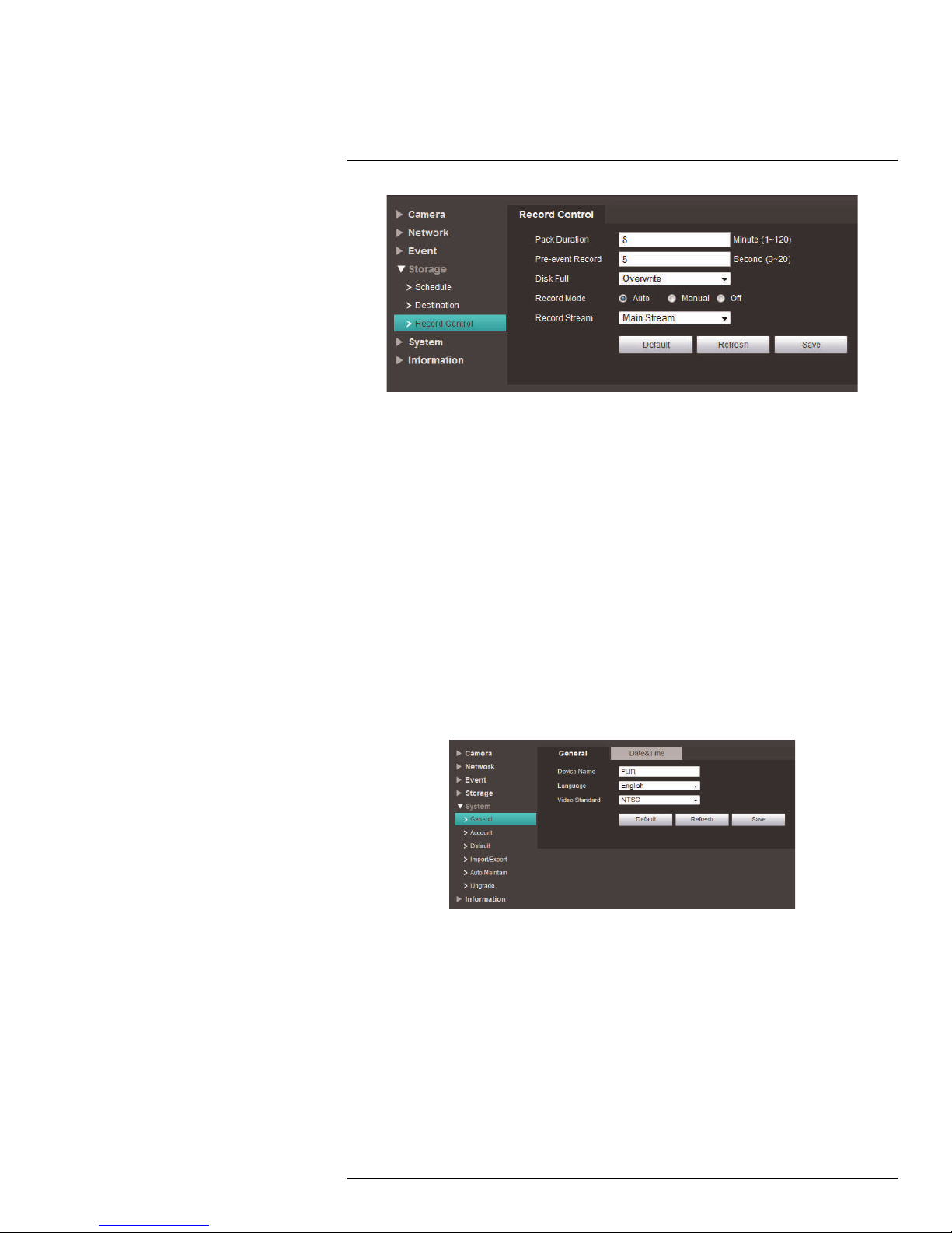
6.4.7 NAS
The NAS tab allows you to set up settings for recording to a NAS (network attached
storage).
To set up NAS settings:
1. Check Enable to enable recording to NAS.
2. Configure the following:
• Server Address: Enter the IP address or DNS address of the NAS.
• Remote directory: Enter the recording directory on the NAS (e.g. share).
NOTE
The recording directory must be located one level below the root directory. For example, share is
acceptable, but not share/recordings.
3. Click Save to save changes.
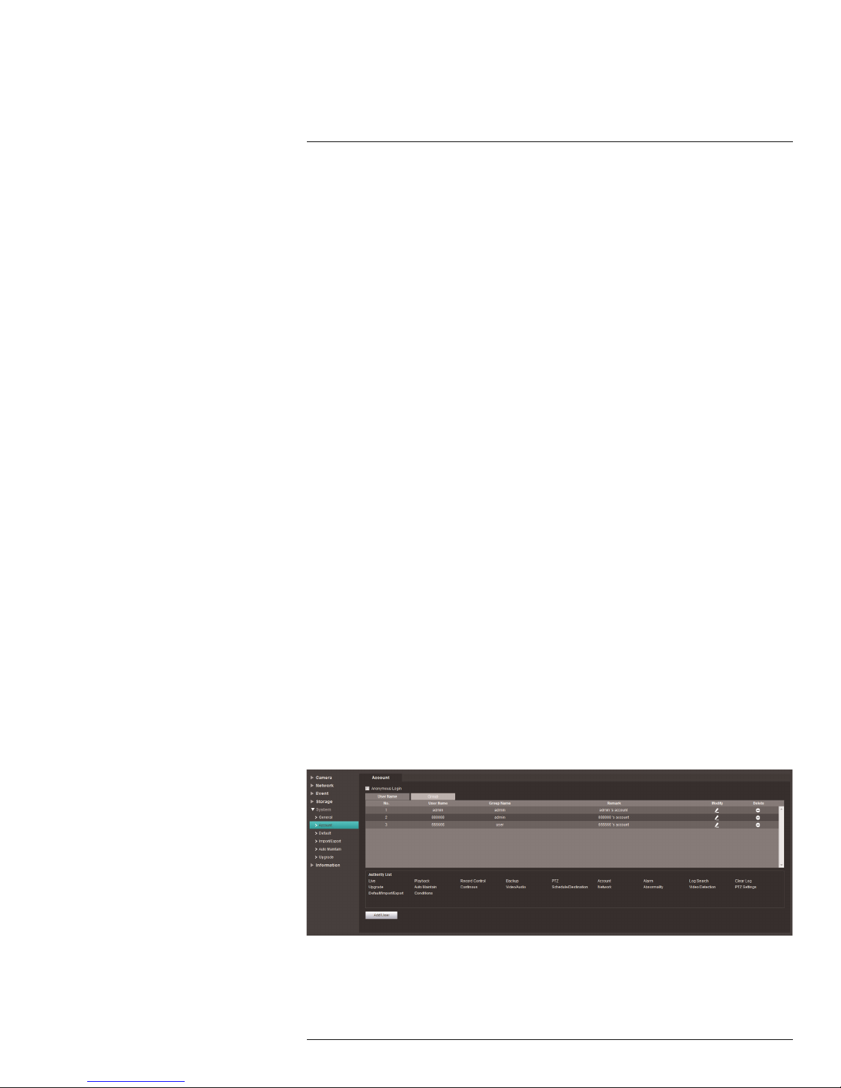
6.4.8 Record Control
The Record Control menu allows you to configure recording parameters for the camera.
#LX400062; r. 1.0/24298/24299; en-US
39
Page 48
6
Setup
To configure recording parameters:
1. Under Pack Duration, enter the duration in minutes that the camera will use to pack
video.
2. Under Pre-event Record, enter the duration in seconds that the camera will pre-record before motion events.
3. Under Disk Full, select Overwrite to overwrite recordings when the recording medium
is full or select Stop to stop recording when the recording medium is full.
• Under Record Mode, select Auto to record according to the schedule, select Man-
ual to record continuously, or select Off to disable recording.
4. Under Record Stream, select Main Stream to record using the Main Stream settings,
or select Substream to record the substream.
5. Click Save to save changes.
6.5 System
6.5.1 General
The General menu allows you to configure general camera settings.
To configure general camera settings:
1. Under Device Name, enter a name for the camera.
2. Under Language, select the language that will be used for the web browser interface.
3. Under Video Standard, select NTSC (North America) or PAL (Europe).
4. Click Save.
6.5.2 Date & Time
The Date & Time tab allows you to set up date and time settings for the IP camera.
#LX400062; r. 1.0/24298/24299; en-US
40
Page 49
6
Setup
To configure date & time settings:
1. Configure the following:
• Date Format: Select the date format.
• Time Format: Select the time format (12 hour or 24 hour).
• Time Zone: Select your time zone.
• Current Time: Enter the current time or click Sync PC to sync your IP camera to
your PC’s clock.
2. If your area uses Daylight Savings Time (DST) check DST Enable. If you enable DST,
configure the following:
• DST Type: Select Date to select a date for the time change or select Week to select
the week and day for the time change.
• Start Time and End Time: Enter the start and end times for Daylight Savings.
3. Check Synchronize with NTP to synchronize the camera clock with an NTP time
server. A constant Internet connection is required to use NTP. If you enable NTP, configure the following:
• NTP Server: Enter the NTP server address.
• Port: Enter the port for the NTP server.
• Update Period: Enter the interval the camera will use to update the time.
4. Click Save.
6.5.3 Account
The Account menu allows you to configure user accounts and user groups. The camera
can support up to 18 user accounts and up to 8 groups. User accounts must be assigned
to a group and inherit permissions from user groups, but an individual user account can be
given less permissions than the group.
The camera includes a unique admin account that cannot be deleted. The admin account
is the only one that can change permissions assigned to user accounts. Accounts given
permission to access the Account menu may change the password for other accounts. Accounts not given permission to access the Account menu may not change any account
passwords, including their own. It is essential to change the password of the admin account from the default to prevent unauthorized access to your camera.
You may also check Anonymous Login to allow users to connect to the camera without
entering a user name or password. Users connecting anonymously are given limited access to the camera: they may only view live video and the Alarm list.
To create a user account:
1. Click Add User.
2. Configure the following:
#LX400062; r. 1.0/24298/24299; en-US
41
Page 50

6
Setup
2.1. User Name: Enter a user name for the user. The user name can be up to 15
characters including letters, numbers, and underscores.
2.2. Password: Enter a password for the user account. Re-enter the password
under Confirm Password.
2.3. Group: Assign the user account to a group. The user account will inherit per-
missions from the group, which will be updated under Authority List.
2.4. Remark: (Optional) Enter a description for the user account.
2.5. Authority List: Use the checkboxes to assign permissions to the user account.
3. Click Save.
To create a user group:
1. Click the Group tab.
2. Click Add Group.
3. Configure the following:
#LX400062; r. 1.0/24298/24299; en-US
42
Page 51

6
Setup
3.1. Group: Enter a name for the group.
3.2. Remark: (Optional) Enter a description for the group.
3.3. Authority List: Use the checkboxes to assign the default permissions for user
accounts added to this group.
4. Click Save.
To modify a user account or group:
1. Select the User or Group tab.
2. Click
next to the account or group you would like to modify.
3. Edit the account or group details and then click Save.
To delete a user account or group:
1. Select the User or Group tab.
2. Click
next to the account or group you would like to delete.
3. Click OK.
6.5.4 Default
Click the Default button and then click OK to reset the camera to default settings. The
camera will reboot.
6.5.5 Import / Export
The Import/Export menu allows you to export your camera’s configuration or import a
saved configuration.
To export the camera’s configuration:
1. Click Export.
2. Select a location on your computer and then click Save.
#LX400062; r. 1.0/24298/24299; en-US
43
Page 52

6
Setup
To import the camera’s configuration:
1. Click Import.
2. Select the configuration file you would like to backup and then click Open.
6.5.6 Auto Maintain
The Auto Maintain menu allows you to reboot the camera manually or on a automatic
schedule. It also allows you to automatically delete old video files.
To manually reboot the camera:
• Click Manual Reboot and then click OK to reboot the camera.
To configure auto reboot:
1. Check Auto Reboot to set the camera to reboot automatically on schedule.
2. Select the day and time for the camera to reboot.
3. Click Save.
To configure auto delete:
1. Check Auto Delete Old Files.
2. Enter the number of days the camera will retain video files.
3. Click Save.
6.5.7 Upgrade
The Upgrade menu allows you to upgrade the camera firmware. When firmware upgrades
are released, they are available for free from www.flirsecurity.com/pro.
#LX400062; r. 1.0/24298/24299; en-US
44
Page 53

6
Setup
To upgrade the camera firmware:
1. Download and extract the firmware from www.flirsecurity.com/pro.
2. Click Browse.
3. Select the firmware file on your computer and then click Open.
4. Click Upgrade. The camera will upgrade the firmware and then reboot.
6.6 Information
6.6.1 Version
The Version menu shows you information related to the product and firmware version.
6.6.2 Log
The Log menu allows you to view system logs for the camera.
To view system logs:
1. Under Start Time and End Time, enter the start time and end time for your search.
2. Under Type, select the type of log you would like to search for: All, Setting, Data,
Event, Record, Account, and Clear Log.
#LX400062; r. 1.0/24298/24299; en-US
45
Page 54

6
Setup
3. Click Search.
• (Optional) Click Backup to save logs to your computer hard drive.
• (Optional) Click Clear to delete all system logs.
#LX400062; r. 1.0/24298/24299; en-US
46
Page 55
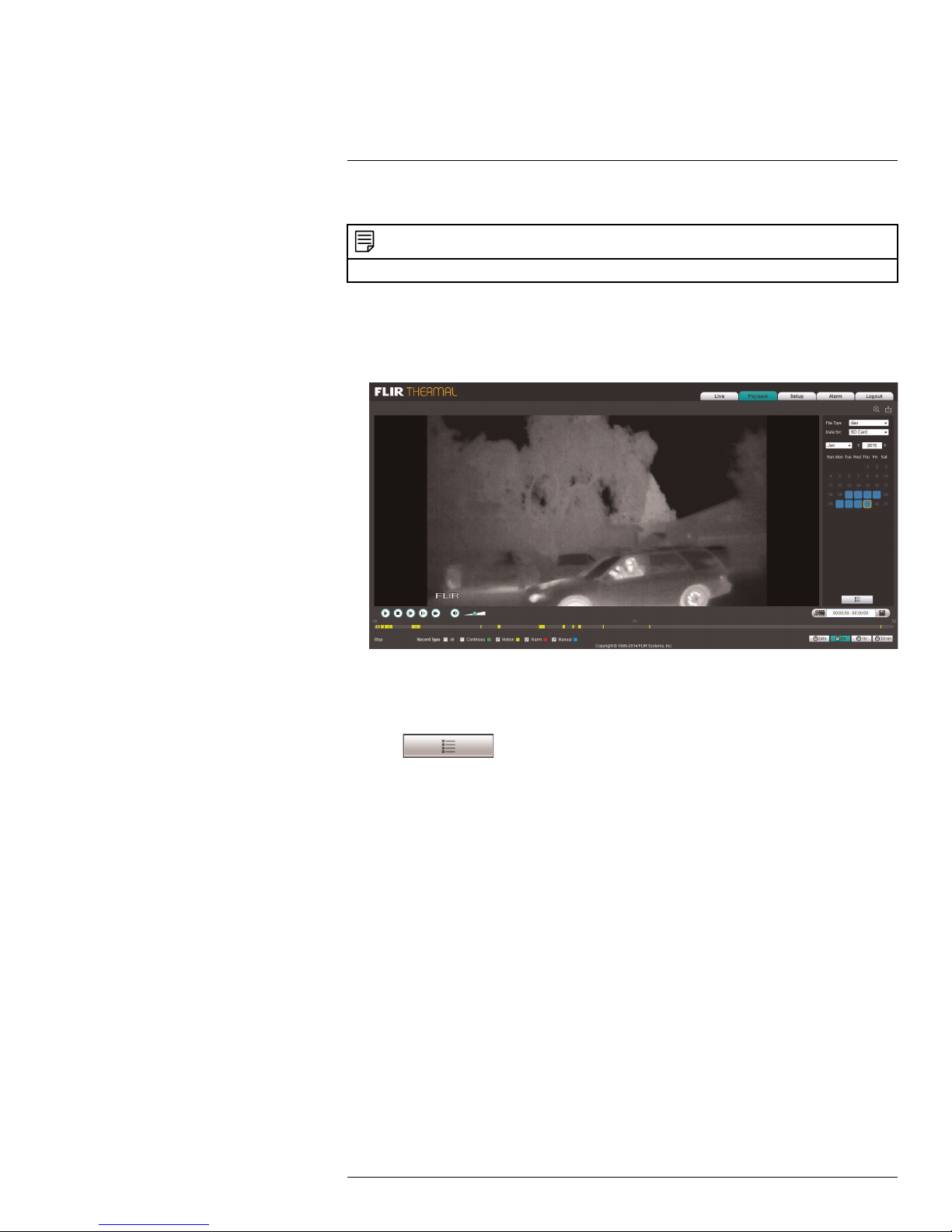
7
Playback (Cameras with microSD
only)
Playback mode allows you to playback video from the camera’s SD / microSD card.
NOTE
Playback is only available if your camera supports on-board recording using an SD / microSD card.
To playback video from the microSD card:
1. Use the calendar to select a day to search for video. The bar on the bottom populates
with video recorded on that day.
2. Click in the time bar to start playback.
OR
1. Click in the calendar to select a day to search for video.
2. Click
. A list appears with video files from the selected day.
#LX400062; r. 1.0/24298/24299; en-US
47
Page 56

7
Playback (Cameras with microSD only)
3. Click a time to select it.
4. Click then to start playback.
7.1 Playback Controls
1. Play
2. Stop
3. Next frame
4. Slow
5. Fast
6. Mute
7. Volume
8. Select playback time
9. Show / hide recording type in time bar
10. Zoom into time bar
#LX400062; r. 1.0/24298/24299; en-US
48
Page 57

7
Playback (Cameras with microSD only)
7.2 Backing up Video Files
You can download video files to your computer hard drive. Video files are saved in (.dav)
format. You can use the video player available from www.flirsecurity.com/pro to play backup video files.
To backup video files:
1. Click in the calendar to select a day to search for video.
2. Click
3. Click
. A list appears with video files from the selected day.
next to the video file you would like to download to your computer’s hard drive.
#LX400062; r. 1.0/24298/24299; en-US
49
Page 58
8
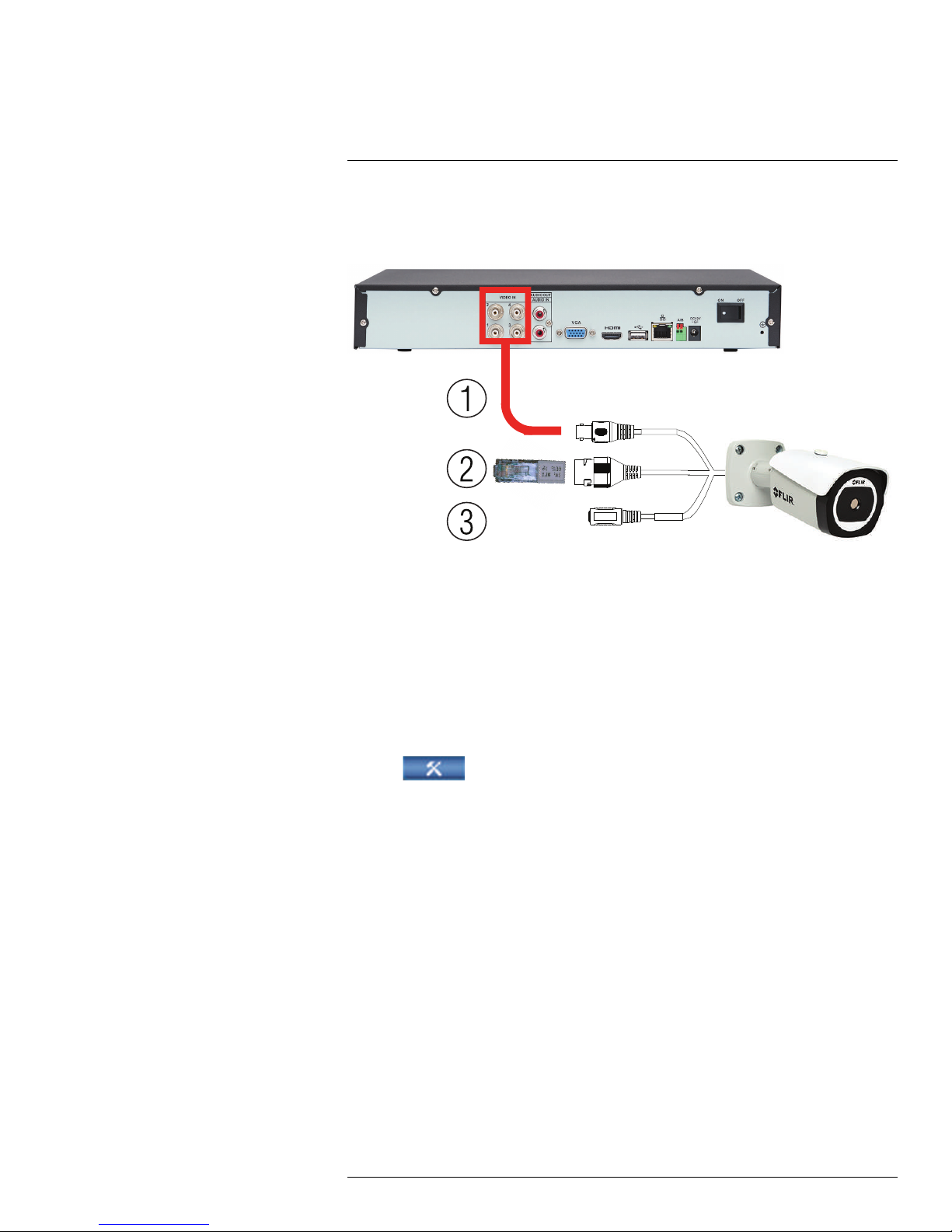
Connecting a Camera in MPX
Mode
When your T43 Series thermal camera is in MPX mode, you can connect it to a FLIR MPX
DVR. To set your camera to MPX mode, insert the MPX terminator before powering on the
camera. See the diagram below for details.
1. Connect the BNC video connector to a Video IN port on the DVR using a coaxial cable
(not included),
2. Connect the MPX terminator to the Ethernet port.
3. Connect the camera to the appropriate power source (not included).
After powering on your DVR, you will have to set communication parameters for your
camera.
To set communication parameters for a camera in MPX mode:
1. Double-click on the channel of the MPX camera.
2. Right-click and click Main Menu.
3. Click
4. Configure the following settings:
• Under Channel, select the channel your MPX camera is connected to.
• Under Control Mode, select HDCVI.
• Under Protocol, select DH-SD1.
5. Click OK to save changes.
8.1 MPX On-Screen Display (OSD)
T43 Series thermal cameras feature an on-screen display (OSD) menu that allows you to
configure thermal image settings and set the video standard to NTSC or PAL.
8.1.1 Accessing the OSD Menu
You can use your a FLIR MPX DVR’s PTZ controls to access the OSD menu.
To access the OSD menu:
1. In Live View, double-click the channel that has the MPX camera connected to open in
full-screen.
and select Setting. Click Pan/Tilt/Zoom.
#LX400062; r. 1.0/24298/24299; en-US
50
Page 59
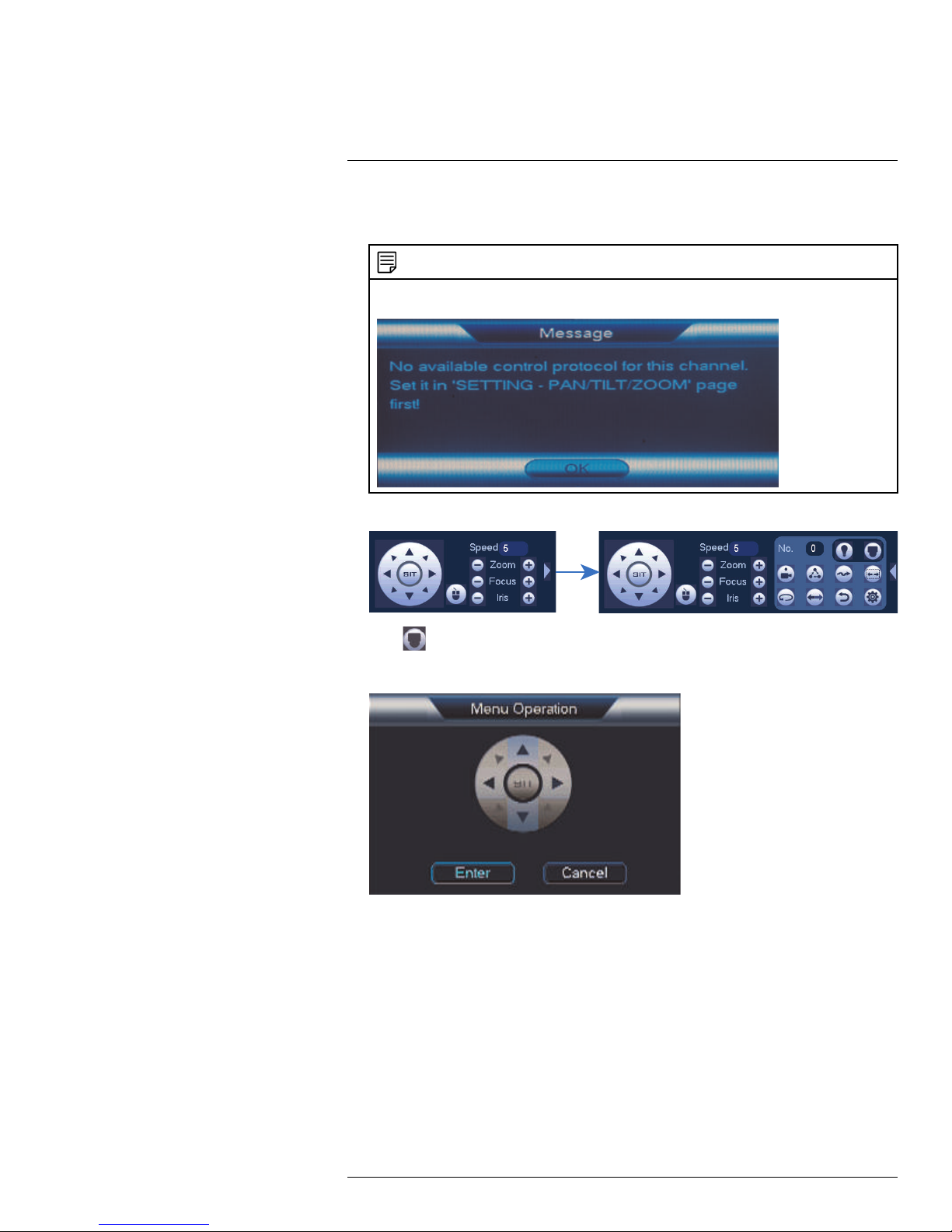
8
Connecting a Camera in MPX Mode
2. Right-click and click Pan/Tilt/Zoom. Enter the system user name and password if
prompted. The PTZ menu opens.
NOTE
The following message will appear when attempting to access the PTZ menu if the communication
parameters have not been correctly set for your camera. See above for details.
3. Click the arrow in the PTZ control window to show advanced controls.
4. Click . The OSD menu appears over the camera image.
5. Use the on-screen controls to configure menu items:
• Up / down arrows: Select menu items.
• Left / right arrows: Change value for menu items.
• Cancel: Exit the OSD menu.
• Enter: Enter the menu item.
#LX400062; r. 1.0/24298/24299; en-US
51
Page 60

8
Connecting a Camera in MPX Mode
8.1.2 OSD Menu Tree
The following table shows settings available in the OSD menu. For more information on
these setting, see 6.1.1 Settings, page 10.
8.1.2.1 T43 Series Bullet Camera MPX OSD
Menu Item Default Option
BRIGHTNESS
SHARPNESS
GAMMA
ROI Full Screen
SMART SCENE (SSO)
COLORIZATION White Hot
EZOOM 0X 0X – 16X
STANDARD NTSC NTSC / PAL
PRESET MODE Default
RESTORE SETTINGS Restore camera to factory defaults.
DEVICE INFORMATION View information about the camera:
EXIT
50 0 – 100
10
3 -8 – 8
15
• SERIAL NUMBER
• SOFTWARE
• FIRMWARE
• VERSION
Exit the OSD menu.
0 – 100 (increments of 5)
• Full Screen
• Ground
• Horizon
• Sky
• Center 25%
• Center 50%
• Center 75%
• Custom
0 – 100 (increments of 5)
• White Hot
• Black Hot
• Ironbow2
• IceFire
• Deafult
• Indoor
• Outdoor
8.1.2.2 T43 Series Mini Bullet Camera MPX OSD
Menu Item Default Option
ROI Full Screen
STANDARD NTSC NTSC / PAL
DEVICE INFORMATION View information about the camera:
• SERIAL NUMBER
• SOFTWARE
• FIRMWARE
• VERSION
EXIT
#LX400062; r. 1.0/24298/24299; en-US
Exit the OSD menu.
• Full Screen
• Ground
• Horizon
• Sky
• Center 25%
• Center 50%
• Center 75%
• Custom
52
Page 61

9
Connecting to Cameras with FLIR
Cloud™ CMS
FLIR Cloud™ Client is a central management software that allows you to view and manage multiple FLIR security systems on a PC or Mac. It includes support for FLIR Cloud™
Services, allowing a simple, secure connection to compatible systems over the Internet
with no network configuration required.
9.1 System Requirements
Your system must meet the system requirements below:
Description Requirement
CPU Core 2 Duo 3.0GHz
Operating System Windows™ 8/7/Vista
Mac OSX 10.7 and above
Memory
Video 512 MB of video memory and above
Network (LAN) 10/100 BaseT Network
Network (WAN) 1 Mbps upstream
9.2 Installing FLIR Cloud™ Client
1. Download and install the client software.
• PC Users: Download and install FLIR Cloud™ Client for PC from
www.flirsecurity.com/pro.
• Mac Users: Download and install FLIR Cloud™ Client for Mac from
www.flirsecurity.com/pro. Double click to extract the software. Then, drag
the software to Applications.
2. Once installation is finished, double-click the FLIR Cloud™ Client icon (
desktop or Applications list.
2GB
High-speed Internet service is required to remotely
connect to your system.
) from the
#LX400062; r. 1.0/24298/24299; en-US
53
Page 62
9
Connecting to Cameras with FLIR Cloud™ CMS
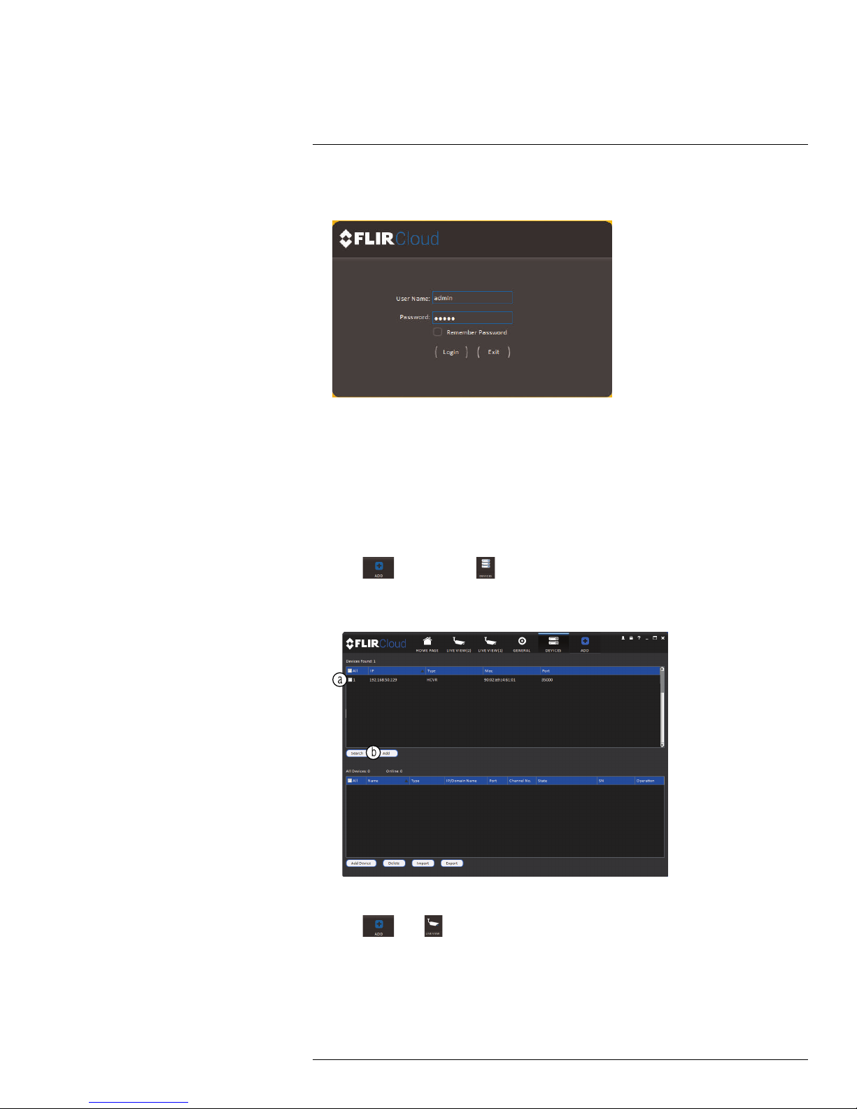
3. Log into the Client Software using the Client Software user name (default: admin) and
password (default: admin) and then click Login.
9.3 Adding a Camera over the Local Network (LAN)
You can add cameras over a local network (LAN). The software will automatically scan the
network for compatible cameras.
Prerequisites:
• Connect the IP camera to a router or switch on the network.
• Install FLIR Cloud™ Client on a computer in the same network as the IP camera.
To add a camera over the LAN:
1. Click
and then click .
2. The client scans your LAN for connected cameras. Check your camera (a) and click
Add (b).
3. Enter the password for your system (default: admin) and click OK.
4. Click
then .
#LX400062; r. 1.0/24298/24299; en-US
54
Page 63
9
Connecting to Cameras with FLIR Cloud™ CMS
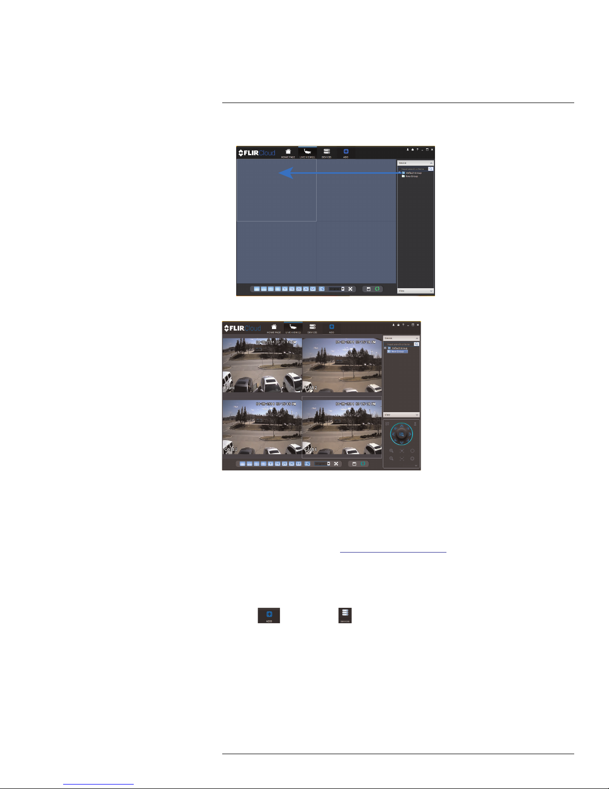
5. Click-and-drag Default Group to the display window to open your camera in live view.
Result
9.4 Adding a Camera over the Internet using a DDNS Address
It is recommended to sign up for a free FLIR DDNS address to connect to compatible
cameras over the Internet.
Prerequisites:
• Create a DDNS account at http://ddns.myddns-flir.com.
• Input the DDNS address into the IP camera locally.
• Port forward the required ports on the router to the camera’s local IP address.
• Install FLIR Cloud™ Client on a remote computer.
To add a camera using a DDNS address:
1. Click
#LX400062; r. 1.0/24298/24299; en-US
and then click .
55
Page 64

9
Connecting to Cameras with FLIR Cloud™ CMS
2. Click Add Device.
3. Enter the following:
3.1. Check By IP/Domain to add a camera using the DDNS address.
3.2. Device Name: Choose a name for your camera of your choice.
3.3. IP/DDNS Address: Enter the Domain Name/URL Request you received in the
email when you registered for DDNS followed by .myddns-flir.com.
NOTE
For example, if your Domain Name/URL Request is tomsmith, enter tomsmith.myddns-flir.
com
3.4. Client Port: Enter the camera’s Client Port.
3.5. User Name: Enter the camera’s User Name (default: admin).
3.6. Password: Enter the system’s Password (default: admin).
4. Click Add.
5. Click
#LX400062; r. 1.0/24298/24299; en-US
then .
56
Page 65

9
Connecting to Cameras with FLIR Cloud™ CMS
6. Click-and-drag Default Group to the display window to open your camera in live view.
Congratulations! You can now connect over the Internet to view and playback video on
your computer.
Result
#LX400062; r. 1.0/24298/24299; en-US
57
Page 66
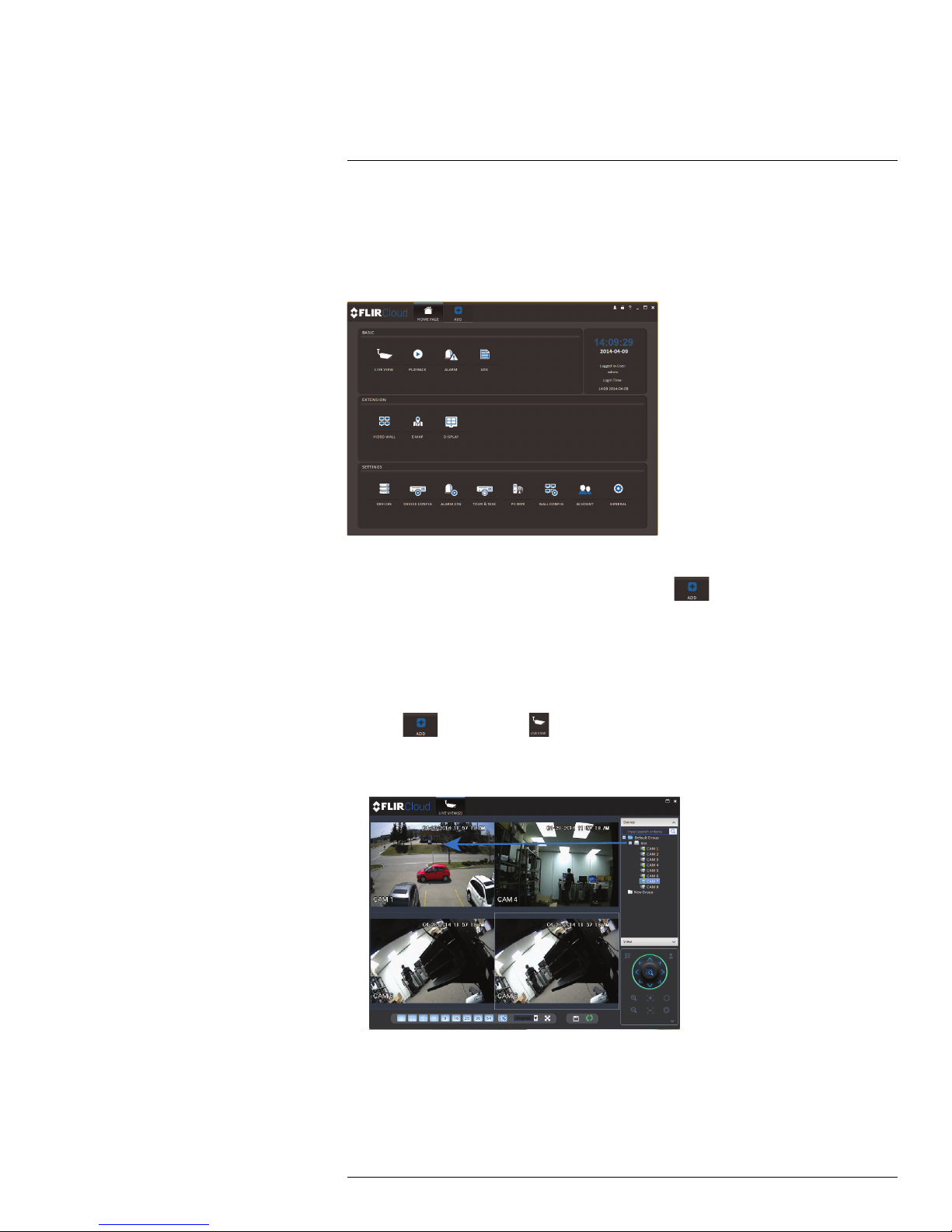
10
Using FLIR Cloud™ Client for PC
or Mac
FLIR Cloud™ Client allows you to connect to multiple systems from a PC or Mac.
10.1 Home Page
The Home Page allows you to access all the tabs within the software. Each tab allows you
to access different features.
To open tabs:
Click a tab from the Home Page to open it or click the
from within any tab to open a new tab.
10.2 Live View
The Live View tab is where you can view live video from connected systems.
To view live video from a system:
1. Click
2. Click and drag a DVR, NVR, group, or individual camera to open live video. To access
individual cameras, you can click + to expand groups or systems.
and then click to create a Live View tab.
button at the top of the screen
#LX400062; r. 1.0/24298/24299; en-US
58
Page 67

10
Using FLIR Cloud™ Client for PC or Mac
10.2.1 Live View Controls
1. Live display: Double-click to expand the area. Right-click to access additional options.
Hold the mouse over the display area to access the camera toolbar.
Camera toolbar:
1.1. Streaming quality: Shows the bitrate and resolution for the stream, and shows
if display is showing the Sub Stream or Main Stream.
1.2. Manual recording: Click to start/stop manual recording.
1.3. Snapshot: Click to save a snapshot.
1.4. Mute/unmute: Click to mute/unmute audio (audio camera required).
1.5. Not supported.
1.6. Instant playback: Plays back the most recently recorded video from the cam-
era. By default, it will play back the last 5 minutes of recorded video from the
camera.
1.7. Digital zoom: Click to enable digital zoom mode. Click and drag over the dis-
play area to zoom on the camera. Then click and drag to pan. Click the icon
again to zoom out.
1.8. Disconnect.
1. Split-screen mode: Click to select split-screen layout.
2. Aspect ratio: Use the drop down menu to select the aspect ratio for the selected
camera. Original uses the actual aspect ratio of the image. Full-win stretches the image to fill up the entire display area.
#LX400062; r. 1.0/24298/24299; en-US
59
Page 68

10
Using FLIR Cloud™ Client for PC or Mac
3. Full-screen: Click to open full-screen mode. Press ESC to exit full-screen mode.
4.
Save view: Click to save the current display layout and open cameras as a view.
Then enter a name for the view.
5.
Start/stop tour: Click to start the tour. During the tour the client will cycle through
all saved views every few seconds. Click again to stop the tour.
6. PTZ Controls: Controls for PTZ cameras (not included). See 10.3 Controlling PTZ
Cameras, page 61 for details.
7. View: Click View to access view menu. Then double-click on a view to open it in the
display area.
8. Devices: Shows a list of groups, cameras, and systems connected to the client. Drag
items to the display area to open live video. Right-click to view additional options.
10.2.2 Opening Live View in Multiple Monitors
If your computer has multiple monitors, you can open more than one Live View tab and
move them to secondary monitors. This allows you to monitor cameras on multiple monitors at the same time.
NOTE
Using multiple monitors significantly increases the amount of computing resources necessary to run the
application and may affect performance.
To open Live View in multiple monitors:
1. Click
and then click to create a Live View tab.
#LX400062; r. 1.0/24298/24299; en-US
60
Page 69

10
Using FLIR Cloud™ Client for PC or Mac
2. Click and drag the tab outside of the client window to create a new window. You can
drag the window to one of the secondary monitors.
Result
10.3 Controlling PTZ Cameras
If you have PTZ cameras (not included), you can control them using the client.
NOTE
You must ensure the PTZ camera is properly connected to your system and your system is configured to
detect it before you can control them using the client.
To control PTZ cameras:
• Click the display area with the PTZ cameras and use the on-screen PTZ controls.
#LX400062; r. 1.0/24298/24299; en-US
61
Page 70

10
Using FLIR Cloud™ Client for PC or Mac
PTZ controls:
1. Open menu: Click to open camera OSD menu controls. This feature may not be supported for all camera models.
2. Move camera: Click the arrows to move the camera.
Click
to open dynamic zoom mode. Then click and drag in the video area to zoom
in the camera on an area.
3. Zoom +/-: Click to zoom the camera in and out.
4. Focus +/-: Click to increase/decrease the focus.
5. Iris +/-: Click to increase/decrease the iris.
6. Advanced: Click to access advanced PTZ controls.
10.3.1 PTZ Presets
Presets will save a camera position for quick retrieval.
To add presets:
1. Click
2. Click
to open the Advanced controls. Select Preset.
.
#LX400062; r. 1.0/24298/24299; en-US
62
Page 71

10
Using FLIR Cloud™ Client for PC or Mac
3. Select the number of the preset you would like to add.
4. Move the camera to the desired position.
5. Click
to save the current position as a preset.
To go to a saved preset:
1. Select the preset number from the list or click
to go to the currently selected
preset.
10.3.2 PTZ Tours
Tours will cycle through a set of presets.
To configure a PTZ tour:
1. Click
2. Click
to open the Advanced controls. Select Tour.
.
3. Under Cruise ID, select the number of the tour you would like to configure.
4. (Optional) Under Cruise Name, enter a name for the tour.
#LX400062; r. 1.0/24298/24299; en-US
63
Page 72

10
Using FLIR Cloud™ Client for PC or Mac
5. Use the chart to select which presets you would like to include in the tour and the order
of presets.
• Preset: Select the preset number.
• Time(s): Enter the time in seconds the camera will remain on the selected preset.
• Operation: Click
to add a preset to the tour. Click to delete a preset from
the tour.
6. Click OK to save changes.
To run a PTZ tour:
1. Select the tour number and click
.
10.3.3 PTZ Pattern
Patterns automatically cycle the camera between two positions.
To create a pattern:
1. Click
to open the Advanced controls. Select Pattern.
2. Select the number of the pattern you would like to set up.
3. Move the camera into the desired start position.
4. Click
to start recording the pattern.
5. Move the camera to the desired end position. Then, click
pattern.
To run a pattern:
1. Select the pattern number and click
#LX400062; r. 1.0/24298/24299; en-US
.
to stop recording the
64
Page 73

10
Using FLIR Cloud™ Client for PC or Mac
10.3.4 PTZ Scan
Scan automatically cycles between a left and right point.
To set up scan mode:
1. Click
to open the Advanced controls. Select Scan.
2. Move the camera to the desired left position and click .
3. Move the camera to the desired right position and click
To run scan mode:
1. Click
.
10.3.5 PTZ Pan
Pan makes the camera continuously pan 360°.
To run Pan mode:
1. Click
2. Click
to open the Advanced controls. Select Pan.
.
.
10.4 Playback
You can use Playback mode to playback video saved on systems connected to the client.
To access Playback mode:
• Click
#LX400062; r. 1.0/24298/24299; en-US
and then click to create a Playback tab.
65
Page 74
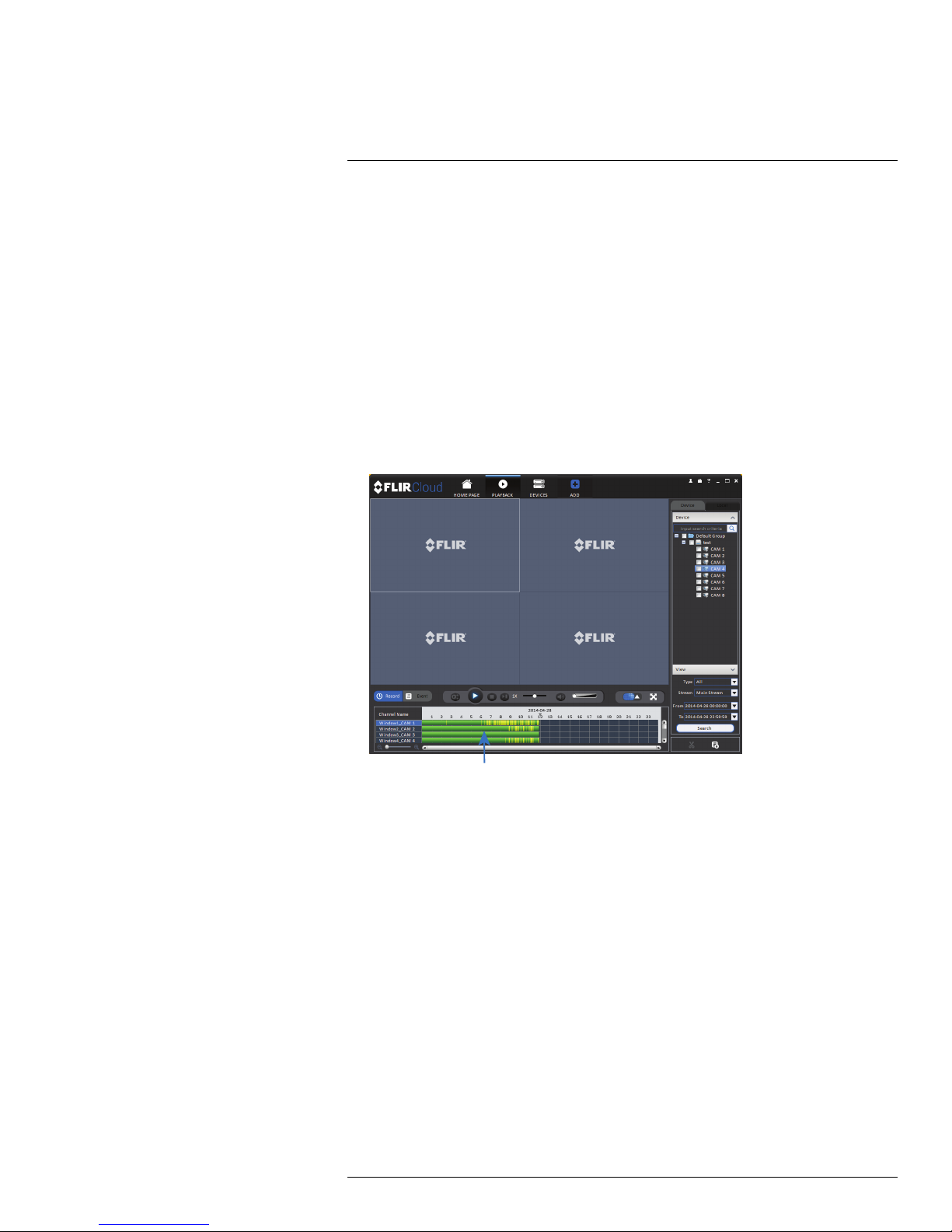
10
Using FLIR Cloud™ Client for PC or Mac
To playback video:
1. Check the channels you would like to play back from in the Device List.
2. Under Type, check the file types you would like to search for.
• All: All recordings.
• General: Continuous recordings.
• MD: Motion recordings.
• Alarm: Alarm recordings. Your system must support alarm devices (not included) to
use this feature.
3. Under Stream, select Main Stream to search for Main Stream recordings (high quality) or Sub Stream to search for Sub Stream recordings (smaller file size).
4. Select the start time and end time for your search under From and To. You may not
search more than 24 hours of video.
5. Click Search. Wait for the client to find video saved to the system.
6. Click inside the play back bar to start playback.
#LX400062; r. 1.0/24298/24299; en-US
66
Page 75
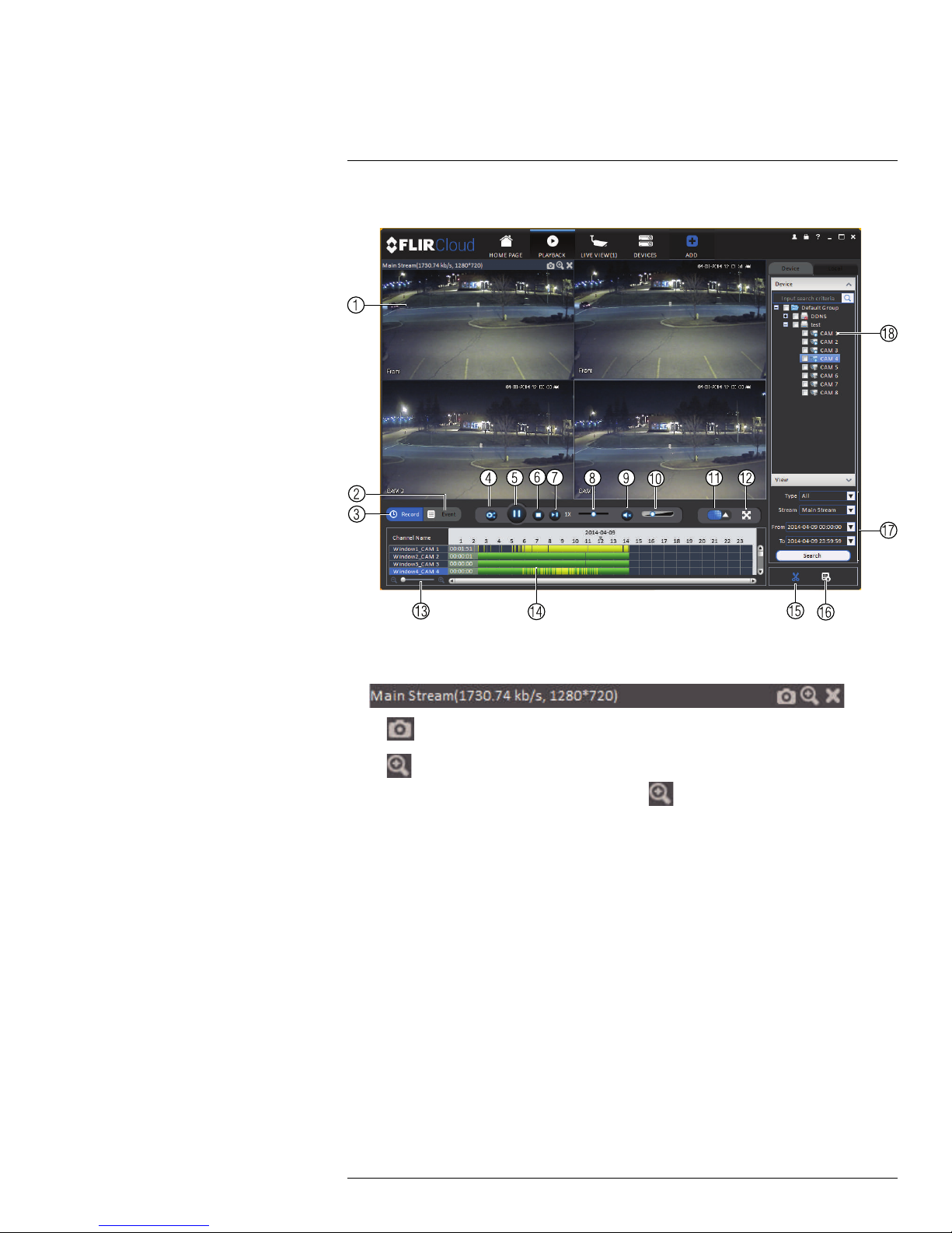
10
Using FLIR Cloud™ Client for PC or Mac
10.5 Playback Controls
1. Display area: Double-click to expand/return to split-screen mode. Hold the mouse
over the display area to open the camera toolbar.
• Snapshot: Click to save a snapshot.
•
Digital zoom: Click to enable digital zoom mode. Then, click and drag to zoom
in. Click and drag to pan the camera. Click
again to zoom out.
2. Event: Click to view recordings based on a list of events and files.
3. Record: Click to view recordings on a timeline.
4. Sync: Click to sync playback between channels. This forces all channels to playback
from the same time.
5. Pause/play.
6. Stop.
7. Frame-by-frame: Click to advance the video by a single frame.
8. Playback speed: Use the slider to adjust the playback speed.
9. Mute.
10. Volume.
11. Split-screen: Select split screen configuration.
12. Full-screen: Click to open playback in full-screen. Press ESC to exit full-screen.
13. Timeline zoom: Use the slider to zoom in/out on the timeline.
14. Playback timeline: Shows recordings from the selected channels on a timeline. Click
inside the timeline to start playback or select a playback time. Each type of recordings
is shown in a different color. Continuous recordings are green, motion recordings are
yellow, and alarm recordings are red.
15. Video clip: Click to start a video clip. You can download video clips to your hard drive.
#LX400062; r. 1.0/24298/24299; en-US
67
Page 76

10
Using FLIR Cloud™ Client for PC or Mac
16. Download list: Click to see a list of files you have downloaded and the progress of
files that are currently downloading.
17. Search: Search for video on the selected channels based on the search parameters
you set.
18. Device list: Select the channels you would like to search or playback video from.
10.6 Downloading Video to your Computer Hard Drive
You can download video to your computer hard drive to save important events or share
them. It is recommended to download video of important events as soon as possible to ensure they are not overwritten by new recordings.
NOTE
PC Users: You may need to run FLIR Cloud™ Client as an administrator to download files to your hard
drive.
To download video files:
1. Start playing back video using the steps in 10.4 Playback, page 65.
2. Click
to start a video clip at the current playback time. Click to stop the video
clip.
3. Configure the following save options:
• Path: Use the default save folder or click Browse to select a different folder.
• File Format: Select Original Format to save to .dav format (requires the video
player). Select AVI to save files to .avi format (can be played in VLC Media Player).
NOTE
The Mac version only supports downloading video to .dav format.
• Download Video Player: Check to save a copy of the video player with the down-
loaded file.
4. Click OK to start the download. A status screen will pop up to show progress on downloaded files.
#LX400062; r. 1.0/24298/24299; en-US
68
Page 77
10
Using FLIR Cloud™ Client for PC or Mac
NOTE
To retrieve downloaded video files:
• PC Users: Browse to the folders listed in General>File.
• Mac Users: Browse to the folders listed in General>File. To get to the default location, open Applications in Finder, right click on FLIR Cloud Client and select Show Package Contents. Then, navigate
to the desired folder.
10.7 Alarm
The Alarm menu allows you to view a list of alarms received by the client software.
NOTE
You must set up alarms in the Alarm CFG menu before they will appear in this list. See 10.12 Alarm CFG,
page 74 for more details.
To access Alarms:
• Click
and then click .
Alarm menu overview:
1. Number of alarms: Shows the number of open alarms.
2. Alarm list: Shows the list of alarms and information on when they occurred and which
systems and channels triggered them.
3. Alarm Process: You can close alarms by selecting one of the options and clicking OK.
#LX400062; r. 1.0/24298/24299; en-US
69
Page 78
10
Using FLIR Cloud™ Client for PC or Mac
4. Options: Check to enable the following:
• Display Link Video: Open live video to monitor alarms on a continuous basis.
• Display Overlay Window: Show the overlay controls. They allow you to enable/dis-
able sound alerts and quickly jump back to the Alarm menu from another tab.
• Pause Refresh: Stop refreshing the live video in the video popup.
10.8 Log
The Log menu allows you to view logs for the client software or to view logs for connected
systems.
To access logs:
• Click
and then click .
To view client logs:
1. Click Client Log to view logs for the client software.
2. Configure the following:
• Start Time/End Time: Select the start and end times to search for logs.
• Log Type: Select the type of logs to search for.
3. Click Search.
To view logs from connected systems:
#LX400062; r. 1.0/24298/24299; en-US
70
Page 79
10
Using FLIR Cloud™ Client for PC or Mac
1. Click Device Log to view logs from connected systems.
2. Configure the following:
• Start Time/End Time: Select the start and end times to search for logs.
• Log Type: Select the type of logs to search for.
• Device Name: Select the system you would like to view logs from.
3. Click Search.
10.9 E-map
E-Map allows you to place cameras over a still image. For example, you can use the EMap to create a virtual map of your cameras over a floor plan of your home or business.
To create an E-map:
1. Click
and then click .
2. Click Add Map.
#LX400062; r. 1.0/24298/24299; en-US
71
Page 80

10
Using FLIR Cloud™ Client for PC or Mac
3. Configure the following:
• Name: Enter a name for your e-map of your choice.
• Picture: Click File and then select a .png, .bmp, or .jpg image on your computer to
use as the e-map.
• Describe (optional): Enter a text description of the e-map.
4. Click Save.
5. Click Edit to edit the e-map.
6. Click and drag cameras from the device list to place them on the map.
To open cameras from the e-map:
1. Click View.
#LX400062; r. 1.0/24298/24299; en-US
72
Page 81
10
Using FLIR Cloud™ Client for PC or Mac
2. Double-click cameras on the map to open live video.
10.10 Devices
The Devices menu is where you can manage systems connected to the client software.
To access the Devices menu:
• Click
and then click .
Devices overview:
1. Devices Found: Shows systems that are connected to the same network as the computer where the client is installed. Once you connect to the system, it moves to the bottom of the screen.
2. Search: Refresh the list of systems connected to the network.
3. Add: Add checked systems to the client software.
4. Device list: Shows a list of systems connected to the client software, and shows which
systems are online.
5. Add Device: Add a remote system using a Device ID or IP/DDNS address.
6. Delete: Delete the selected system.
7. Import: Import a list of systems from a saved .xml file.
8. Export: Export a list of currently connected systems to an .xml file. This is useful if you
need to re-install the software or if you want to open the same list of systems on a different computer.
9. Delete: Delete system.
10. Manual connect/disconnect: Manually connect/disconnect the system.
#LX400062; r. 1.0/24298/24299; en-US
73
Page 82

10
Using FLIR Cloud™ Client for PC or Mac
11. Edit: Edit the connection details for the system.
10.11 Device Config
The Device Config menu allows you to remotely configure settings for connected systems.
To access the Device Config menu:
• Click
and then click .
• Click on a system in the device list to see the settings available for that system and then
configure settings as needed.
NOTE
The settings available depend on the model of system you have.
10.12 Alarm CFG
The Alarm CFG menu allows you to configure alarms for the client software. The client
software will alert you by popping up live video and playing sound alerts.
NOTE
Alarm upload must be enabled on the system in order for it to send the alarm to the client software.
To create alarms:
1. Click
and then click .
2. Click Add to create a new alarm.
#LX400062; r. 1.0/24298/24299; en-US
74
Page 83

10
Using FLIR Cloud™ Client for PC or Mac
3. In the Alarm sources menu, you set up the parameters that trigger the alarm.
• Under Alarm Type, select the alarm type that will trigger an alarm. For example,
you can select Motion Detect for the alarm to be triggered by motion.
• Select the systems or channels you would like to trigger an alarm. Continuing the
example, if CAM 1 is selected, the alarm will be triggered if there is motion on CAM
1.
• Click Next.
#LX400062; r. 1.0/24298/24299; en-US
75
Page 84

10
Using FLIR Cloud™ Client for PC or Mac
4. In the Alarm link menu, you set up the responses to alarms. Select the channels that
will pop up or alarm out devices (not included; not all systems support alarm out devices) that will be triggered by an alarm.
For each channel selected, configure the following:
• Video: Pop up a window with live video from the selected channel, like the one
below.
• Record: Record video from the selected channel.
NOTE
PC Users: You may need to run the client software as admin to record.
• Preset: If you select a PTZ camera, you can select the preset that will be activated
when an alarm occurs.
• Stay Time: Enter how many seconds the video window will stay open or record
when an alarm occurs.
5. Click Next.
6. In the Period window, configure times the alarm will be activated.
7. Click Confirm to save the alarm.
#LX400062; r. 1.0/24298/24299; en-US
76
Page 85

10
Using FLIR Cloud™ Client for PC or Mac
To manage alarms:
1. Export: Export current list of alarms as an xml file.
2. Import: Import list of alarms.
3. Delete: Delete selected alarm.
4. Add: Add new alarm.
5. Alarms.
6. On/off: Click to enable/disable alarm.
7. Delete: Click to delete alarm.
8. Edit: Click to edit alarm settings.
10.13 Tour & Task
The Tour & Task menu is where you can set up custom views for the system. You can also
set up tours, which sets the client to automatically cycle through views.
To start a tour:
• Click
in Live View to start a tour. The live view will automatically cycle through all
views you have set up in the Tour & Task menu. Click again to stop the tour.
To add views:
1. Click
and then click .
2. Click + to create a new view.
#LX400062; r. 1.0/24298/24299; en-US
77
Page 86

10
Using FLIR Cloud™ Client for PC or Mac
3. Under Name, enter a name for your view.
4. Under Stay Time, enter the number of seconds the view will be shown before the client switches to the next view.
5. Select the split-screen mode you would like to use for the view and then click and drag
channels to the empty grid areas to select channels to be shown in the view.
6. Click Save to save the view. Or click Add More to save the view and create another
view.
10.14 Account
The Account menu is where you can set up user accounts and passwords for the client
software. To simplify management, you can group user accounts according to role. A role
determines the permissions an individual user account can have.
To access the account menu:
• Click
and then click .
10.14.1 Managing User Accounts
By default, the client software includes an admin account that has full access to all features of the software and all connected systems. You can add user accounts with customized levels of access.
NOTE
The admin account cannot be deleted. The default user name for the admin account is admin and the
default password is admin.
#LX400062; r. 1.0/24298/24299; en-US
78
Page 87

10
Using FLIR Cloud™ Client for PC or Mac
To create a user account:
1. Click Add.
2. Configure the following settings for the user account:
• User Name: Enter a user name for the account.
• Role: Select the role for the user account. By default, the user account gains all the
permissions of the role selected, but you can deactivate permissions as needed.
• Password/Confirm Password: Enter the password for the user account.
• Remarks (Optional): Enter a text description of the user account.
• User Rights: Check the permissions that will apply to the user account. If you click
on LiveView, Playback, and PTZ, you can select which channels the user account
can access in the Channel List section.
3. Click Save to create the account.
To switch between user accounts:
• Click
.
To modify a user account:
NOTE
Admin accounts with Account Setup permissions can change account passwords. A user cannot change
his own password.
• Click next to the user account you would like to modify. Edit the user account de-
tails and click Save.
#LX400062; r. 1.0/24298/24299; en-US
79
Page 88

10
Using FLIR Cloud™ Client for PC or Mac
To delete a user account:
1. Click
next to the user account you would like to delete. Click OK to confirm.
10.14.2 Managing Roles
Roles make it easier to manage user accounts by determining the permissions an individual user account can have. By default, a new user account is given all the permissions of
the role they are assigned to.
To create a role:
1. Click the Role tab.
2. Click Add.
3. Configure the following settings for the role:
• Role Name: Enter a name for the role.
• Remarks (Optional): Enter a text description of the role.
• Role Rights: Check the permissions that will apply to user accounts assigned this
role. If you click on LiveView, Playback, and PTZ, you can select which channels
may be accessed in the Channel List section.
4. Click Save.
To modify a role:
• Click
#LX400062; r. 1.0/24298/24299; en-US
next to the role you would like to modify. Edit the role details and click Save.
80
Page 89

10
Using FLIR Cloud™ Client for PC or Mac
To delete a user account:
1. Click
next to the role you would like to delete. Click OK to confirm.
10.15 General
The General menu is where you can configure application settings for the client software.
To access the General menu:
• Click
and then click .
10.15.1 Basic
The Basic menu contains general settings for the client software.
The Basic menu contains the following settings:
• Log Saved Time: Select the number of days you would like the client to save log
entries.
• Instant Playback Time: Select the number of minutes the system will go back when
you start an instant playback.
• Network Capability: Select the speed of your computer’s network connection.
• Resume Live View State: Check for the client to resume live view when it starts up.
The live view will open to the last view that you had open.
• Auto login application: Check for the client to automatically login when it starts up
without entering a user name or password.
• Auto Login Windows: Not supported.
• Language: Select the language for the client software.
• Sync Time: Check to have the client software sync time with your computer’s system
time. Select the time the software will sync the time. Click Sync Now to manually sync
the time.
• Time Format: Select 12–Hour or 24–Hour time format. You must close the client and
restart it to apply this setting.
NOTE
Click Save to save setting changes.
10.15.2 File
The File menu allows you to select the folders where the client software will save downloaded video files and snapshots.
#LX400062; r. 1.0/24298/24299; en-US
81
Page 90
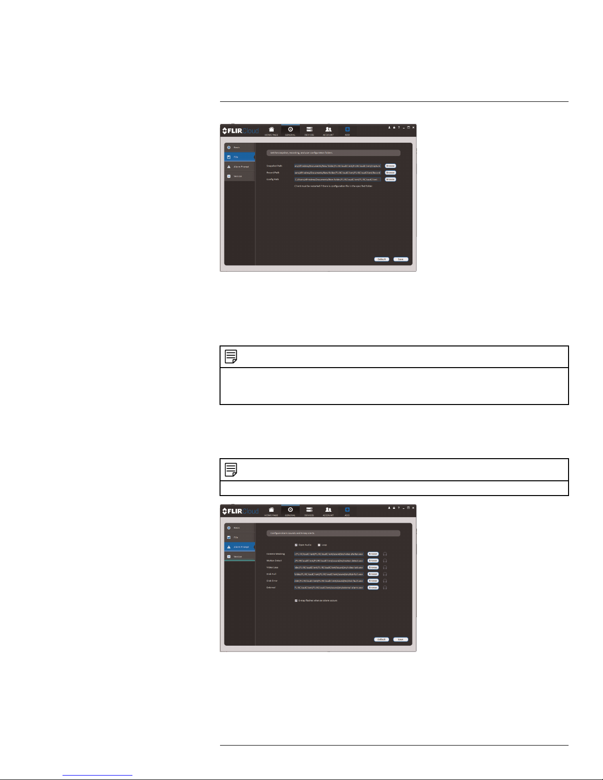
10
Using FLIR Cloud™ Client for PC or Mac
The File menu contains the following options:
• Snapshot Path: Click Browse to select the default folder to save snapshots.
• Record Path: Click Browse to select the default folder to save video recordings.
• Config Path: Click Browse to select the folder where the client will save software con-
fig files.
NOTE
Click Save to save setting changes.
PC Users: You may need to run the client software as admin to save files to enable snapshot or video
recording.
10.15.3 Alarm Prompt
The Alarm Prompt menu allows you to configure audio alerts. The client will play audio
alerts when events occur. You can replace the default sounds with any .wav file.
NOTE
You must configure alarms in the Alarm CFG menu before the client will play alarm sounds.
The Alarm Prompt menu has the following options:
• Open Audio: Check to enable audio alerts.
• Loop: Check to repeat audio alerts until acknowledged.
• Camera Masking: Select or preview the sound that will play for camera masking
alarms.
#LX400062; r. 1.0/24298/24299; en-US
82
Page 91
10
Using FLIR Cloud™ Client for PC or Mac
• Motion Detect: Select or preview the sound that will play for motion detection.
• Video Loss: Select or preview the sound that will play for video loss alarms.
• Disk Full: Select or preview the sound that will play for disk full alarms.
• Disk Error: Select or preview the sound that will play for disk errors.
• External: Select or preview the sound that will play for external alarms (triggered by
sensor devices, which may not be supported on all systems).
• E-map flashes when alarm occurs: If the camera has alarms enabled and is added
to an e-map, a
NOTE
Click Save to save changes.
appears on the e-map when an event occurs.
10.15.4 Version
The Version menu shows you which version of the client software you are using. It is recommended to always run the latest version of the software from www.flirsecurity.com/pro.
#LX400062; r. 1.0/24298/24299; en-US
83
Page 92

11
Smartphone and Tablet Apps
FLIR Cloud is a free mobile app that is compatible with iPhone, iPad and Android devices.
Platform Supported Versions
and Devices
iOS iPhone/iPad FLIR Cloud™ Apple App Store
Android Android FLIR Cloud™ Google Play Store
See www.flirsecurity.com/pro for the latest list of supported apps and devices.
11.1 iPhone
FLIR Cloud is an iPhone app that allows you to remotely view your IP camera.
11.1.1 Prerequisites
• Port 80 and 35000 (or your HTTP and Client Ports, if you have changed them) must be
port forwarded on your router to your camera’s IP address.
• You must create a DDNS account, and have the DDNS settings configured in your IP
camera.
• The IP camera must have Internet access.
• You must have a DDNS address to log in remotely.
• An iTunes account.
App Name Get App From
NOTE
You will need to create an iTunes account before you can download the app. An iTunes store account
requires a valid credit card number. The app is free of charge.
11.1.2 Connecting to your IP camera on an iPhone
1. Download FLIR Cloud™ for free from the App Store.
2. Tap on the FLIR Cloud™ icon (
NOTE
The first time it opens, the app will ask for permission to send push notifications and to access Photos. It will only send notifications if you enable motion-activated push notifications in the Push Config
menu. It needs access to Photos to save snapshots and video clips to the local storage on your mobile device.
3. Tap then .
4. Configure the following:
) to start the app.
#LX400062; r. 1.0/24298/24299; en-US
84
Page 93
11
Smartphone and Tablet Apps
4.1. Register Mode: Select IP/Domain.
4.2. Name: Choose a name for your IP camera of your choice.
4.3. Address: Enter the IP address or DDNS address of your IP camera. (e.g. tom-
smith.myddns-flir.com).
4.4. Client Port: Enter the Client Port (default: 35000).
4.5. Username: Enter the IP camera’s User Name (default: admin).
4.6. Password: Enter the IP camera’s Password (default: admin).
5. Tap Start Live Preview.
6. The app opens in Live View and streams video from your camera.
11.1.3 Live View Interface
You can use FLIR Cloud™ in portrait and landscape mode.
Live View Overview
1. Menu: Tap to bring up the Menu.
2. Display Area: Double-tap to open a channel in full screen. Swipe left or right to select
a different page of channels.
#LX400062; r. 1.0/24298/24299; en-US
85
Page 94
11
Smartphone and Tablet Apps
3. Pages: Shows the number of pages available and highlights the currently selected
page.
4. Split: Select the split-screen layout.
5. Snapshot: Tap to take a snapshot from the currently selected channel.
6. Control Bar: Contains the following options. Swipe left or right to access more options.
6.1. Quick Playback: Tap to start/stop quick playback.
6.2. PTZ Controls: Open/close PTZ controls. PTZ camera required.
6.3. Streaming Quality: Open/close streaming quality panel.
6.4. Not supported.
6.5. Not supported.
6.6. Not supported.
6.7. Not supported.
6.8. Color Settings: Tap to access color controls for the currently selected camera.
7. Manual record: Tap to start/stop manual recording.
8. Connect/disconnect all: Connect to/disconnect from all previously added cameras.
9. Access Favorites.
10. Device List: Tap to open a list of devices. You can use the Device List to open multiple
systems or cameras at once.
11.1.4 Controlling PTZ Cameras
If you have PTZ cameras, you can control them from the app.
To control PTZ cameras:
1. Tap the display area the PTZ camera is connected to.
2. Tap
to open PTZ controls.
PTZ Controls
#LX400062; r. 1.0/24298/24299; en-US
86
Page 95
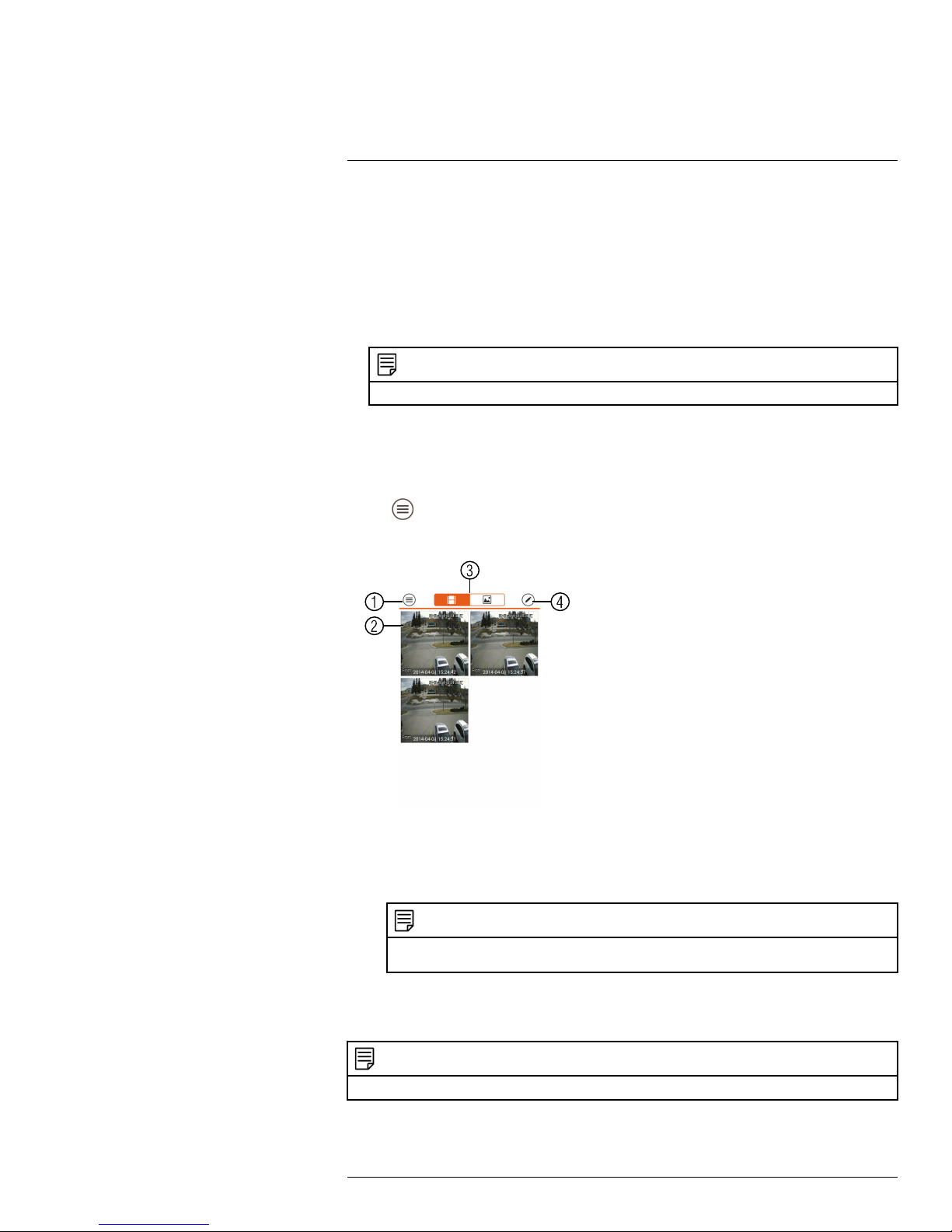
11
Smartphone and Tablet Apps
1. Live Display: Swipe to move the camera. Pinch to zoom in/out.
2. Iris: Tap to show iris controls.
3. Focus: Tap to show focus controls.
4. Zoom: Tap to show zoom controls.
5. PTZ/EPTZ: Tap to switch between PTZ and EPTZ mode. Use PTZ mode to control
PTZ cameras. Use EPTZ mode to activate digital zoom mode on non-PTZ cameras.
6. Goto preset: Tap to access preset controls. Then use the sliders to select a preset
and then tap the checkmark to goto the preset.
NOTE
You must set presets for the camera using the system’s local menus before you can use this feature.
11.1.5 Viewing Snapshots and Videos with Local Files
If you have saved snapshots or videos using the app, you may open them with Local Files.
To access Local Files:
• Tap
to access the Menu, and then tap Local Files.
Local Files Overview
1. Menu: Return to Menu.
2. Files: Tap to open files.
3. File Type: Tap the options to select video files or snapshots.
4. Options: Tap to delete or export files to your device’s local storage.
NOTE
Exported snapshots and video files are saved to the Photos app. Video files are saved to MP4
format.
11.1.6 Using Playback Mode on iPhone
You can access recorded video on your system using your iPhone.
NOTE
You must enable Sub Stream Recording to use playback mode on mobile devices.
#LX400062; r. 1.0/24298/24299; en-US
87
Page 96

11
Smartphone and Tablet Apps
To use Playback Mode:
1. Tap
to access the Menu, and then tap Video Playback.
2. Tap + and select a channel to playback.
3. Select the date then the start and end times to playback.
#LX400062; r. 1.0/24298/24299; en-US
88
Page 97
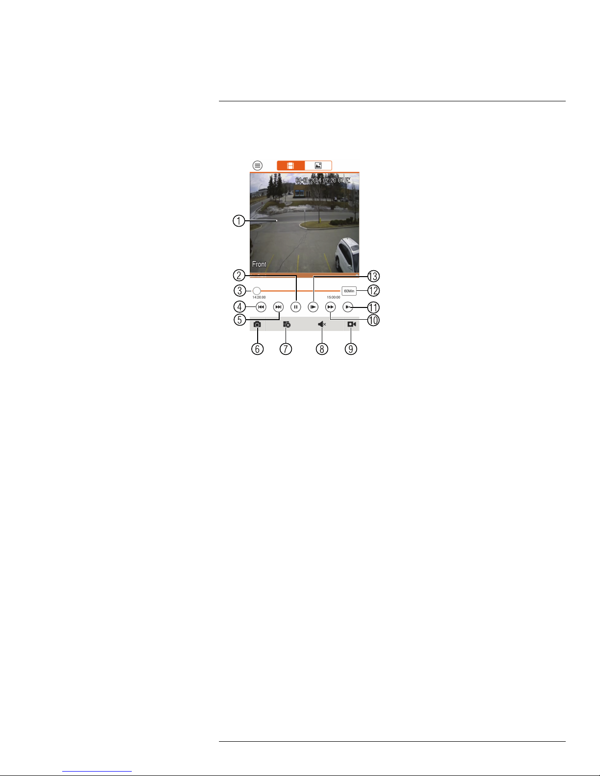
11
Smartphone and Tablet Apps
4. Use the on-screen controls to control playback.
Playback Controls
4.1. Display Area: Double-tap to open in full-screen.
4.2. Play/pause.
4.3. Time Bar: Tap inside the bar to fast forward or rewind.
4.4. Previous: Select previous video file.
4.5. Next: Select next video file.
4.6. Snapshot: Tap to take a snapshot from the selected camera.
4.7. Stop All: Stop playback on all channels.
4.8. Not supported.
4.9. Manual Record: Tap to start/stop recording to your mobile device’s local
storage.
4.10. Fast.
4.11. Slow.
4.12. Time Range: Tap to change the range of time shown in the time bar.
4.13. Next frame.
11.1.7 Enabling Push Notifications
You can have the app send push notifications to the notifications area on your device when
one of your cameras detects motion. Once you have received a push notification, you can
select it to open live video or a snapshot attachment from the camera that detected motion.
#LX400062; r. 1.0/24298/24299; en-US
89
Page 98

11
Smartphone and Tablet Apps
NOTE
Your cameras must have motion detection activated to receive push notifications.
To enable Push Notifications:
1. Tap
to access the Menu, and then tap Push Config.
2. Tap the system you would like to configure.
#LX400062; r. 1.0/24298/24299; en-US
90
Page 99

11
Smartphone and Tablet Apps
3. Tap Motion Detect and then check each channel you would like to receive push notifications from.
4. Tap to save changes. You will now receive a notification when one of the selected
cameras detect motion.
11.1.8 Using the Event List
The Event List menu shows a list of events that were sent to your device via push
notifications.
NOTE
You must configure push notifications before you can use the Event List.
To access the Event List:
• Tap
to access the Menu, and then tap Event List.
#LX400062; r. 1.0/24298/24299; en-US
91
Page 100
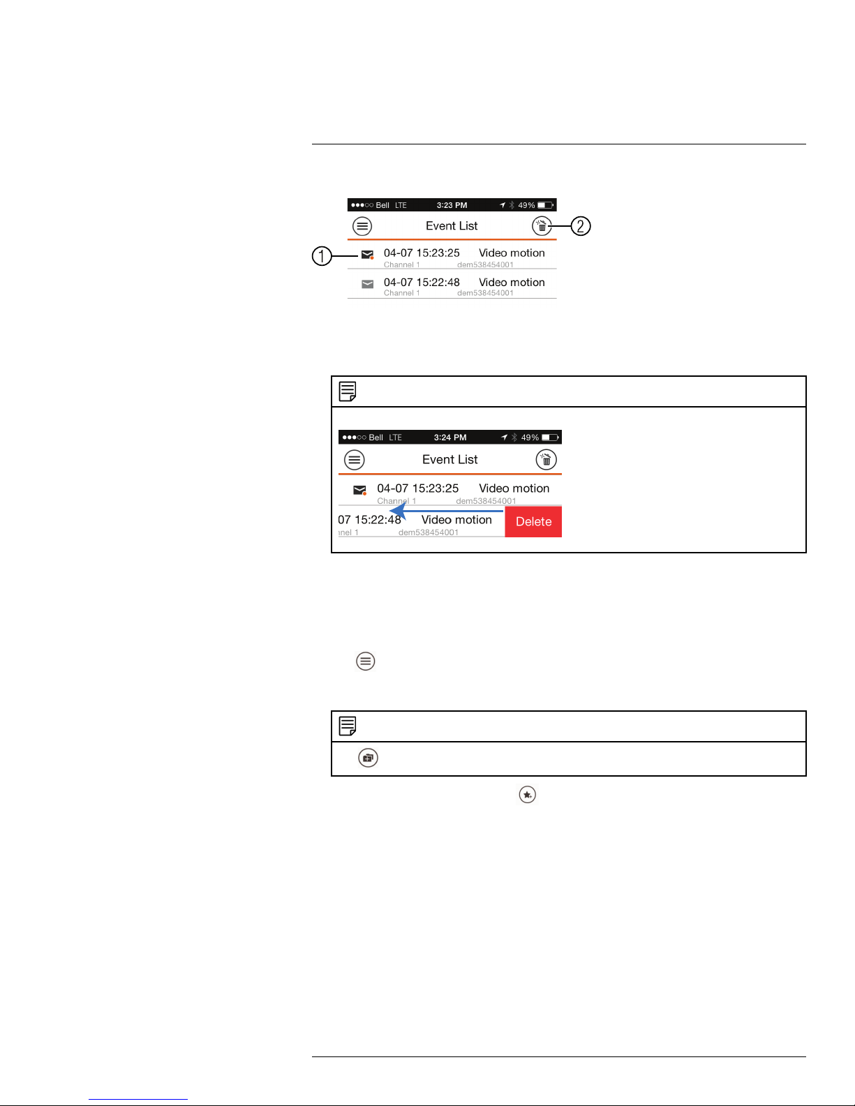
11
Smartphone and Tablet Apps
Event List Overview
1. Events: Shows the details of each motion detection event. Tap the event to view the
video or snapshot.
2. Delete All: Tap to delete all events in the Event List.
NOTE
To delete a single event, swipe it to the left and then tap Delete.
11.1.9 Using Favorites
Favorites allows you to select a group of cameras as a favorite. You can then quickly bring
up the group of cameras in Live View without having to individually select each camera.
To use Favorites:
1. Tap
to access the Menu, and then tap Favorites.
2. Tap a group to configure an existing group.
NOTE
Tap
to create a new group and then enter a name for the new group.
3. To add cameras to the group, tap .
#LX400062; r. 1.0/24298/24299; en-US
92
 Loading...