

Page 1
Notice to customer
Changing and calibrating lenses
Table of contents
1 Thank you! ...... ... ..... ........ ..... ... ..... ... ..... ... ..... ........ ........ ..... ........ ........ ....... 1
2 Applicability . ..... ... ..... ........ ........ ..... ... ..... ........ ........ ............. ........ ........ ..... . 1
3 Changing lenses (FLIR Exx series) ... ........ ............. ........ ........ ..... ... ..... ... ..... ... 2
4 Changing lenses (FLIR T5xx series)..... ........ ........ ..... ........ ........ ........ ..... ... ..... 5
5 Calibrating the lens–camera combination ..... ..... ........ ........ ..... ... ..... ... ..... ... ..... . 8
6 Customer support ... ........ ........ ..... ........ ........ ........ ..... ........ ........ ..... ... ..... ... . 9
7 Appendix ....... ........ ........ ..... ........ ........ ........ ..... ... ..... ........ ........ ..... ... ..... . 10
1 Thank you!
Thank you for choosing a product from FLIR Systems. We hope that the product will
meet your expectations and that you will consider us again for your future needs.
2 Applicability
Note Part numbers subject to change and/or amendment without further notice.
Please check http://support.flir.com for latest applicability data.
2.1 Lens applicability
Sales order P/N Item P/N Product denomination
T199588 T199106 Lens 14° + case
T199590 T199104 Lens 42° + case
T199589 T199105 Lens 24° + case
2.2 Camera applicability
P/N Product denomination
78502-0101 FLIR E75 24°
78504-0101 FLIR E75 24° + 14°
78506-0101 FLIR E75 24° + 14° & 42°
78505-0101 FLIR E75 24° + 42°
78503-0101 FLIR E75 42°
78507-0101 FLIR E75 42° + 14°
78502-0201 FLIR E85 24°
78504-0201 FLIR E85 24° + 14°
78506-0201 FLIR E85 24° + 14° & 42°
78505-0201 FLIR E85 24° + 42°
78503-0201 FLIR E85 42°
78507-0201 FLIR E85 42° + 14°
78502-0301 FLIR E95 24°
78504-0301 FLIR E95 24° + 14°
78506-0301 FLIR E95 24° + 14° & 42°
78505-0301 FLIR E95 24° + 42°
78503-0301 FLIR E95 42°
78507-0301 FLIR E95 42° + 14°
79302-0101 FLIR T530 24°
79304-0101 FLIR T530 24° + 14°
79306-0101 FLIR T530 24° + 14° & 42°
79305-0101 FLIR T530 24° + 42°
79303-0101 FLIR T530 42°
Copyright
© 2017, FLIR Systems, Inc.
All rights reserved worldwide. Names and marks
appearing herein are either registered trademarks
or trademarks of FLIR Systems and/or its
subsidiaries. All other trademarks, trade names or
company names referenced herein are used for
identification only and are the property of their
respective owners.
Document identity
Publ. No.: T810264
Release: AC
Commit: 45029
Head: 45029
Language: en-US
Modified: 2017-09-18
Formatted: 2017-09-18
Website
http://www.flir.com
Customer support
http://support.flir.com
Disclaimer
Specifications subject to change without further
notice. Models and accessories subject to
regional market considerations. License
procedures may apply. Products described herein
may be subject to US Export Regulations. Please
refer to exportquestions@flir.com with any
questions.
1 (10)
www.flir.com
Page 2
Notice to customer
Changing and calibrating lenses
© 2017, FLIR Systems, Inc.
#T810264; r. AC/45029/45029; en-US
P/N Product denomination
79307-0101 FLIR T530 42° + 14°
79302-0201 FLIR T540 24°
79304-0201 FLIR T540 24° + 14°
79306-0201 FLIR T540 24° + 14° & 42°
79305-0201 FLIR T540 24° + 42°
79303-0201 FLIR T540 42°
79307-0201 FLIR T540 42° + 14°
3 Changing lenses (FLIR Exx series)
Note If the new lens has not been used with the camera before, the lens–camera com-
bination must be calibrated after the lens has been mounted. See section 5 Calibrating
the lens–camera combination, page 8 for information on how to do this.
Note Do not touch the lens surface when you change lenses. If this happens, clean
the lens according to the instructions in 7.1 Infrared lens, page 10.
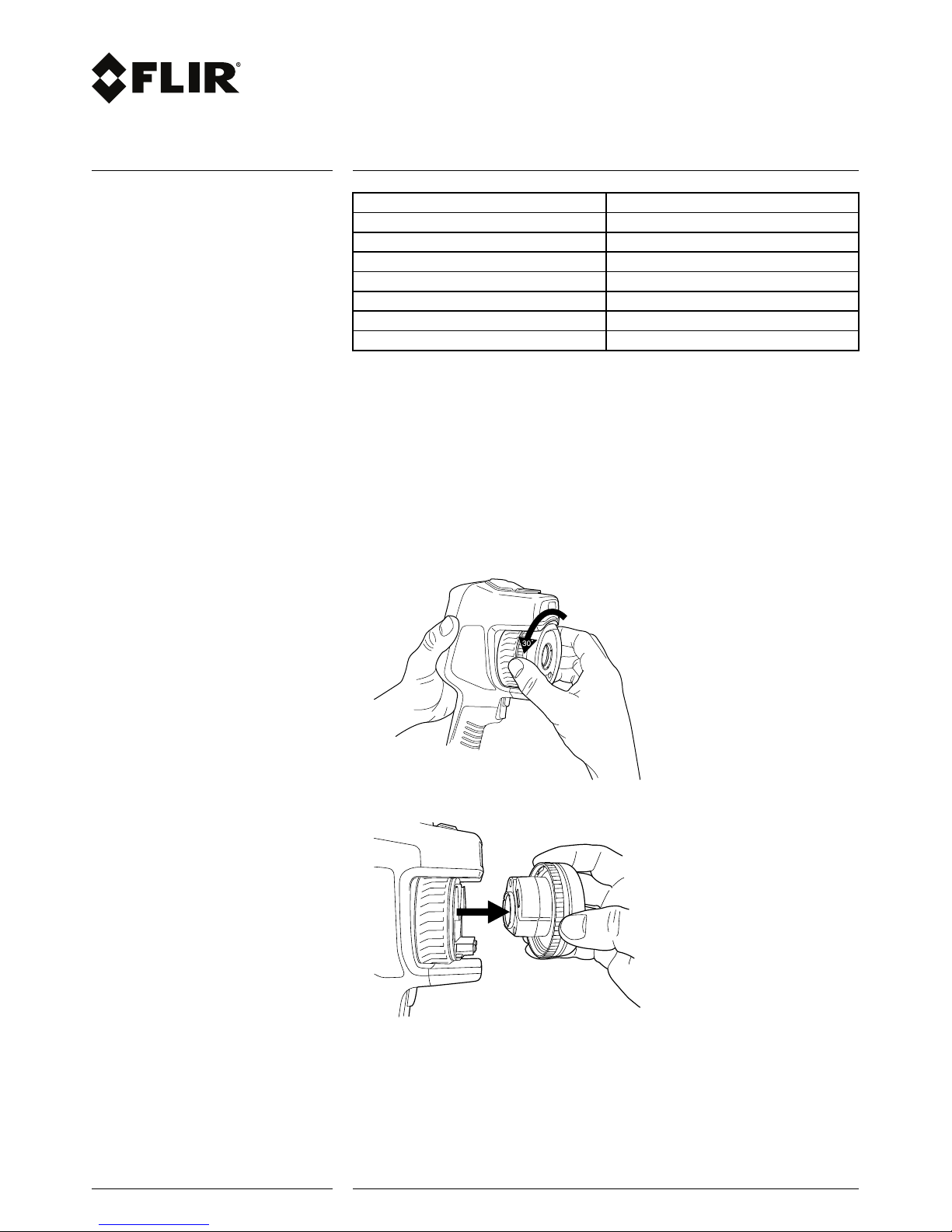
Follow this procedure:
1. Take a firm grip around the inner ring of the lens. Rotate the inner ring 30° counterclockwise until it stops.
2. Carefully pull out the lens.
2 (10)
www.flir.com
Page 3
Notice to customer
Changing and calibrating lenses
© 2017, FLIR Systems, Inc.
#T810264; r. AC/45029/45029; en-US
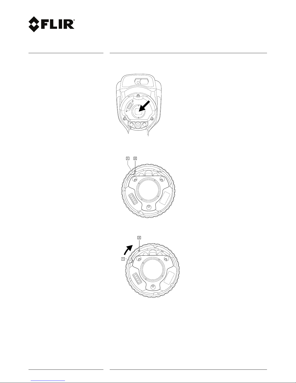
3. The infrared detector is now fully exposed. Do not touch this surface. If you see dust
on the detector, follow the instructions in 7.2 Infrared detector, page 10.
4. Make sure that the inner ring of the camera lens is fully in its open position.
• Correct: The tooth (1) is in its end position at the black stop pin (2).
• Wrong: You must rotate the inner ring until the tooth (1) reaches the black stop pin
(2).
3 (10)
www.flir.com
Page 4

Notice to customer
Changing and calibrating lenses
© 2017, FLIR Systems, Inc.
#T810264; r. AC/45029/45029; en-US
5. Carefully push the lens into position.
6. Rotate the inner ring of the lens 30° clockwise. The lens makes a click when it locks
in place.
7. Make sure that the two index marks are aligned, indicating that the lens is locked in
place.
4 (10)
www.flir.com
Page 5

Notice to customer
Changing and calibrating lenses
© 2017, FLIR Systems, Inc.
#T810264; r. AC/45029/45029; en-US
4 Changing lenses (FLIR T5xx series)
Note If the new lens has not been used with the camera before, the lens–camera com-
bination must be calibrated after the lens has been mounted. See section 5 Calibrating
the lens–camera combination, page 8 for information on how to do this.
Note Do not touch the lens surface when you change lenses. If this happens, clean
the lens according to the instructions in 7.1 Infrared lens, page 10.
Follow this procedure:
1. Take a firm grip around the inner ring of the lens. Rotate the inner ring 30° counterclockwise until it stops.
2. Carefully pull out the lens.
5 (10)
www.flir.com
Page 6

Notice to customer
Changing and calibrating lenses
© 2017, FLIR Systems, Inc.
#T810264; r. AC/45029/45029; en-US
3. The infrared detector is now fully exposed. Do not touch this surface. If you see dust
on the detector, follow the instructions in 7.2 Infrared detector, page 10.
4. Make sure that the inner ring of the camera lens is fully in its open position.
• Correct: The tooth (1) is in its end position at the black stop pin (2).
• Wrong: You must rotate the inner ring until the tooth (1) reaches the black stop pin
(2).
6 (10)
www.flir.com
Page 7

Notice to customer
Changing and calibrating lenses
© 2017, FLIR Systems, Inc.
#T810264; r. AC/45029/45029; en-US
5. Carefully push the lens into position.
6. Rotate the inner ring of the lens 30° clockwise. The lens makes a click when it locks
in place.
7. Make sure that the two index marks are aligned, indicating that the lens is locked in
place.
7 (10)
www.flir.com
Page 8

Notice to customer
Changing and calibrating lenses
© 2017, FLIR Systems, Inc.
#T810264; r. AC/45029/45029; en-US
5 Calibrating the lens–camera combination
5.1 Introduction
Before a new lens can be used with the camera, the lens–camera combination must be
calibrated.
This is a process that previously had to be performed by a FLIR service department, but
for the FLIR Exx series and FLIR T5xx series the calibration can be performed by the
user, using a calibration target. The calibration target is included in the lens package.
5.2 Procedure
Note The images below show a FLIR Exx series camera, but the procedure is similar
for FLIR T5xx series cameras.
Follow this procedure:
1. Dip the calibration target in water for 1 second and let the excess drip off.
2. Tape or hang the calibration target on a wall.
8 (10)
www.flir.com
Page 9

Notice to customer
Changing and calibrating lenses
© 2017, FLIR Systems, Inc.
#T810264; r. AC/45029/45029; en-US
3. Mount the new lens on the camera according to the procedure in section 3 Changing
lenses (FLIR Exx series), page 2 or section 4 Changing lenses (FLIR T5xx series),
page 5. When the lens is mounted, the calibration wizard starts automatically.
4. From a distance of 2 m (6.6 ft.), aim the camera toward the crosshair, using the laser
pointer. The camera will take a picture automatically.
NOTE
Make sure the camera’s optical path is perpendicular to the calibration target. See the image below.
5. In the camera, align the thermal and visual images (indicated by the two squares in
the image below), using the touchscreen arrows. The lens–camera combination is
now calibrated.
To repeat the procedure at a later time, go to Settings > Camera information.
6 Customer support
Do not hesitate to contact our Customer Support Center at http://support.flir.com if you
experience problems or have any questions about your product.
9 (10)
www.flir.com
Page 10

Notice to customer
Changing and calibrating lenses
© 2017, FLIR Systems, Inc.
#T810264; r. AC/45029/45029; en-US
7 Appendix
7.1 Infrared lens
7.1.1 Liquids
Use one of these liquids:
• A commercial lens cleaning liquid with more than 30% isopropyl alcohol.
• 96% ethyl alcohol (C
2H5
OH).
7.1.2 Equipment
Cotton wool
CAUTION
If you use a lens cleaning cloth it must be dry. Do not use a lens cleaning cloth with the liquids that are
given in section 7.1.1 above. These liquids can cause material on the lens cleaning cloth to become
loose. This material can have an unwanted effect on the surface of the lens.
7.1.3 Procedure
Follow this procedure:
1. Soak the cotton wool in the liquid.
2. Twist the cotton wool to remove excess liquid.
3. Clean the lens one time only and discard the cotton wool.
WARNING
Make sure that you read all applicable MSDS (Material Safety Data Sheets) and warning labels on containers before you use a liquid: the liquids can be dangerous.
CAUTION
• Be careful when you clean the infrared lens. The lens has a delicate anti-reflective coating.
• Do not clean the infrared lens too vigorously. This can damage the anti-reflective coating.
7.2 Infrared detector
7.2.1 General
Even small amounts of dust on the infrared detector can result in major blemishes in the
image. To remove any dust from the detector, follow the procedure below.
Note
• This section only applies to cameras where removing the lens exposes the infrared
detector.
• In some cases the dust cannot be removed by following this procedure: the infrared
detector must be cleaned mechanically. This mechanical cleaning must be carried
out by an authorized service partner.
CAUTION
In Step 2 below, do not use pressurized air from pneumatic air circuits in a workshop, etc., as this air
usually contains oil mist to lubricate pneumatic tools.
7.2.2 Procedure
Follow this procedure:
1. Remove the lens from the camera.
2. Use pressurized air from a compressed air canister to blow off the dust.
10 (10)
www.flir.com
 Loading...