

FLIR SR-Series, SR-100, SR-100P, SR-50, SR-35 Installation And Operation Manual
...
S
S
T
h
h
err
e
T
IInnssttaallllaattiioonnaannddO
R--
R
m
m
S
S
all
a
errii
Oppeerraattiioonn
e
C
C
e
e
a
a
s
s
m
m
err
e
Maannuuaall
M
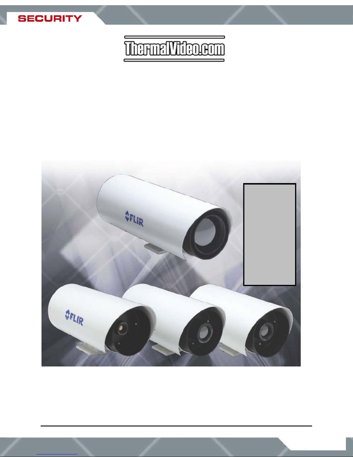
Camera
Models:
SR-100
SR-100P
SR-50
SR-35
a
a
SR-19
VSR-6
ThermalVideo.com
Your Source for Modern Thermal Imaging Systems
P.O. BOX 4242
Middletown, NY 10941
PH: + 1 888 919 2263
PH Intl: + 1 845 343 4077
FX: + 1 845 343 4299
supp ort@thermalvideo.com
427-0014-00-10 Revision 150 Copyright © 2007 FLIR Systems, Inc. 1
January 2008
ww w.therma l v i d eo.com

ThermalVideo.com
PO BOX 4242
Middletow, NY 10940
Toll Free: 1-888-919-2263
Intl.: +1-845-343-4077
Fax: 1-845-343-4299
www.thermalvideo.com
tnemucoD Number: 427-0014-00-10
noisiveR Number: 150
:etaD January 2008
EXPORT RESTRICTIONS
The information contained in this document may be controlled for export purposes by
the United States Government. Diversion contrary to US law is prohibited. For more
information, contact FLIR Systems, Inc. This document and data disclosed herein or
herewith is not to be reproduced, used, or disclosed in whole or in part to anyone
without the permission of FLIR Systems, Inc.
PROPRIETARY
The data in this publication shall not be disclosed without permission and shall not be
duplicated, used, or disclosed in whole or in part except to the extent provided in any
contract of which this document is made a part. This restriction does not limit the
customer’s right to use information contained in this document if it is obtainable from
another source without restriction. The data subject to this restriction are contained in all
sheets of this document and related drawings and document specifications herein. FLIR
reserves the right to make changes to its products or specifications at any time, without
notice, in order to improve design or performance and
product.
COPYRIGHT
Copyright © 2007 by FLIR Systems, Inc. All rights reserved. This publication, or any
parts thereof, may not be reproduced in any form without the express written permission
of FLIR Systems, Inc.
Pelco is a registered trademark of Pelco. Windows is a registered trademark of Microsoft Corporation.
to supply the best possible
427-0014-00-10 Revision 150 Copyright © 2007 FLIR Systems, Inc. 2

TABLE OF CONTENTS
1.0 WARNINGS AND CAUTIONS ...................................................................... 5
2.0 INTRODUCTION ........................................................................................... 6
2.1 Advantages of Thermal Imaging......................................................................... 7
2.2 Serial Remote Control ........................................................................................ 8
2.3 Camera Enclosures ............................................................................................ 9
2.4 Package Contents ............................................................................................ 10
3.0 INSTALLATION .......................................................................................... 11
3.1 Accessing the Electrical Connections............................................................... 11
3.2 Ground Connection ..........................................................................................12
3.3 Input Power ......................................................................................................13
3.4 Sealed Cable Glands........................................................................................ 13
3.5 Analog Video Output ........................................................................................14
3.6 Camera Mounting ............................................................................................. 14
4.0 SR-100 INSTALLATION ............................................................................. 15
5.0 SR-100P INSTALLATION........................................................................... 17
6.0 VSR-6, SR-19, SR35, SR-50 INSTALLATION............................................ 20
7.0 OPERATING THE SR-SERIES THERMAL CAMERA................................ 23
7.1 Thermal Imaging............................................................................................... 23
7.2 Configuration and Control................................................................................. 23
7.3 Pelco Keyboard Control.................................................................................... 24
7.4 Flat Field Correction (FFC)............................................................................... 24
8.0 CARING FOR YOUR SR-SERIES THERMAL CAMERA ........................... 25
8.1 Temperature ..................................................................................................... 25
8.2 Maintenance ..................................................................................................... 25
8
.3 Troubleshooting Problems................................................................................ 26
9.0 SR-SERIES CAMERA SPECIFICATIONS.................................................. 28
9.1 SR-Series Camera Dimensions........................................................................ 29
9.2 SR-100P Specifications.................................................................................... 31
10.0 KBD300 COMMANDS FOR USE WITH SR-100 AND SR-100P.......... 32
11.0 SR-100 & SR-100P CONTROL USING TVIS-7 USER INTERFACE ... 33
12.0 REFERENCES...................................................................................... 40
427-0014-00-10 Revision 150 Copyright © 2007 FLIR Systems, Inc. 3
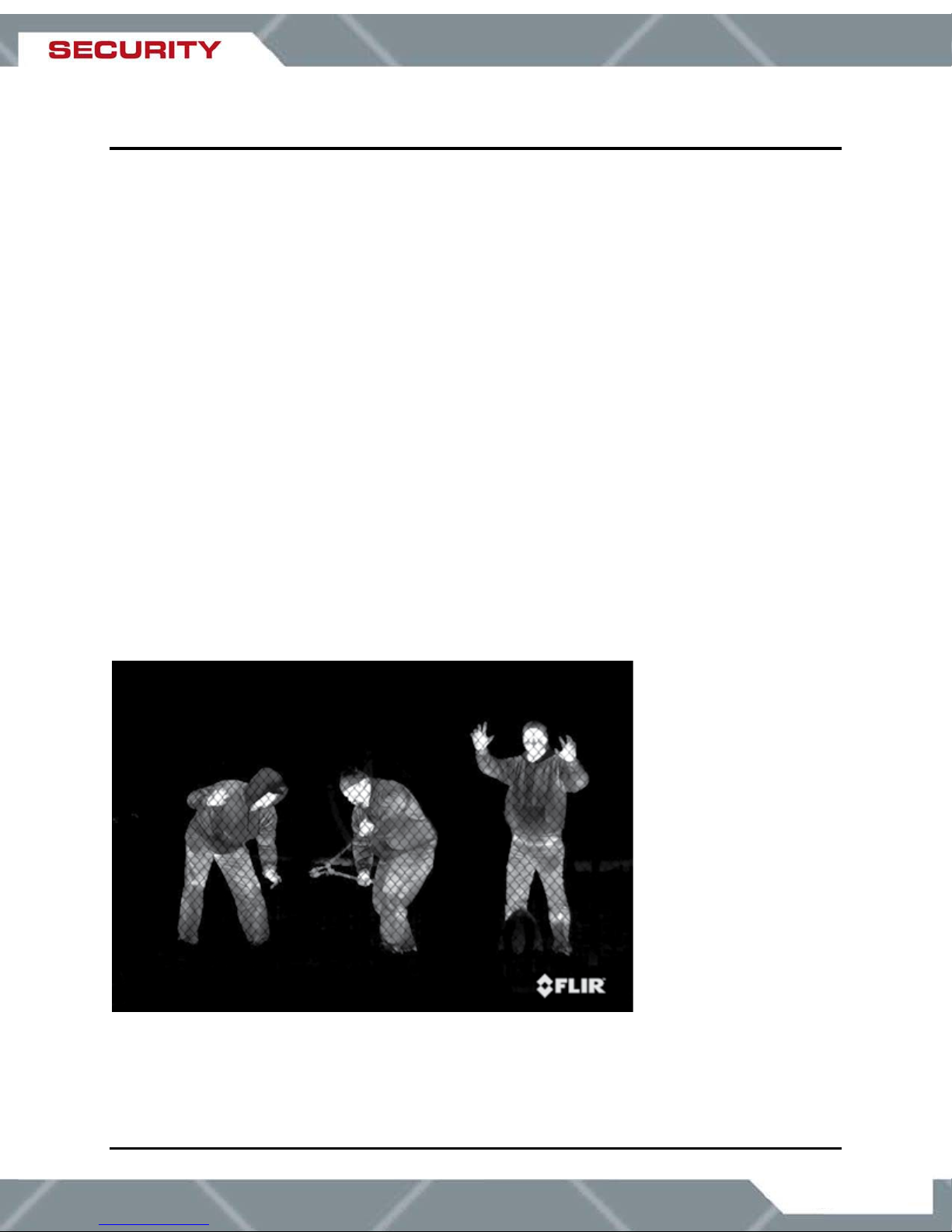
TABLE OF FIGURES
Figure 1: Thermal image from SR-Series camera ........................................................................4
Figure 2 : Daylight camera on left; Thermal image on right ..........................................................6
Figure 3: Backlit daylight camera on left; thermal image on right .................................................7
Figure 4: White Hot palette on left, Black Hot palette on right ......................................................9
Figure 5: SR-35 Camera with and without the Environmental Enclosure .....................................9
Figure 6: SR-100P with Sun Shroud...........................................................................................10
Figure 7: Rear view of SR-Series camera ..................................................................................11
Figure 8: Earth Ground Connection ............................................................................................12
Figure 9: SR-100 Connection Terminal ......................................................................................15
Figure 10: Screw Terminal Connector ........................................................................................16
Figure 11: SR-100P with Sun Shroud.........................................................................................17
Figure 12: SR-100P Enclosure Rear ..........................................................................................19
Figure 13: Mating connector as seen from end of cable.............................................................18
Figure 14: Front view of SR-Series camera................................................................................ 20
Figure 15: SR-Series Connections (VSR-6, SR-19, SR-35, and SR-50) .................................... 21
Figure 16: Tongue
Figure 17: Camera Side View .....................................................................................................29
Figure 18: Camera Rear View ....................................................................................................29
Figure 19: Enclosure
and Groove Alignment..................................................................................22
Mounting Foot (all cameras except for SR-100P).....................................30
Figure 1: Thermal image from SR-Series camera
427-0014-00-10 Revision 150 Copyright © 2007 FLIR Systems, Inc. 4
1.0 WARNINGS AND CAUTIONS
Caution! This guide uses the term Caution! to indicate a potentially hazardous situation, which,
if not avoided, may result in bodily harm or injury, damage to the camera, or other property
damage.
Protect Your Investment
The camera should be installed by a trained professional according to local codes and industry-
standard safe practices.
Proper ESD protocol should be followed while working inside the unit.
The camera is a precision optical instrument and should not be exposed to excessive shock or
vibration.
When not in use, replace the lens cap over the objective lens. When the lens cap is not in place,
avoid pointing the system directly at extremely high-intensity radiation sources, such as the sun,
lasers, arc welders, e
Great care should be used with your camera’s optics. They are delicate and can be damaged by
improper cleaning. Only clean the lens in the manner described in section 8.0 Caring for your
SR-Series Thermal Camera.
tc. This warning applies whether or not the system is powered.
Legal Considerations
Camera and audio surveillance may be prohibited by laws that vary from country to country.
Check the laws in your local region before using this product for surveillance purposes.
Support
If you have questions that are not covered in this manual, or need service, contact FLIR
Customer Support at (805) 964-9797 for additional information prior to returning your SR-Series
Thermal Camera. In the US, you can also reach FLIR Customer Support at (888) 747-FLIR
(747-3547).
All thermal imaging systems are subject to export control. Please contact FLIR for export
compliance information concerning your application or geographic area.
427-0014-00-10 Revision 150 Copyright © 2007 FLIR Systems, Inc. 5
2.0 INTRODUCTION
The SR-Series Thermal Camera you have purchased is a sophisticated thermal imaging
camera that provides excellent night visibility and situational awareness, even in absolute
darkness. The camera has a standard video output that works with digital video recording
devices, video motion detection software or off-the-shelf video encoders.
FLIR’s powerful SR-Series thermal security cameras compliment and complete your security
camera network. They turn night into day, allowing you to see intruders invisible to the naked
eye. SR-Series cameras create video images from infrared thermal energy (heat), and perform
well at night and day, in good weather and bad. The SR Series thermal surveillance camera
system is intended for various commercial and industrial applications, including security and
surveillance.
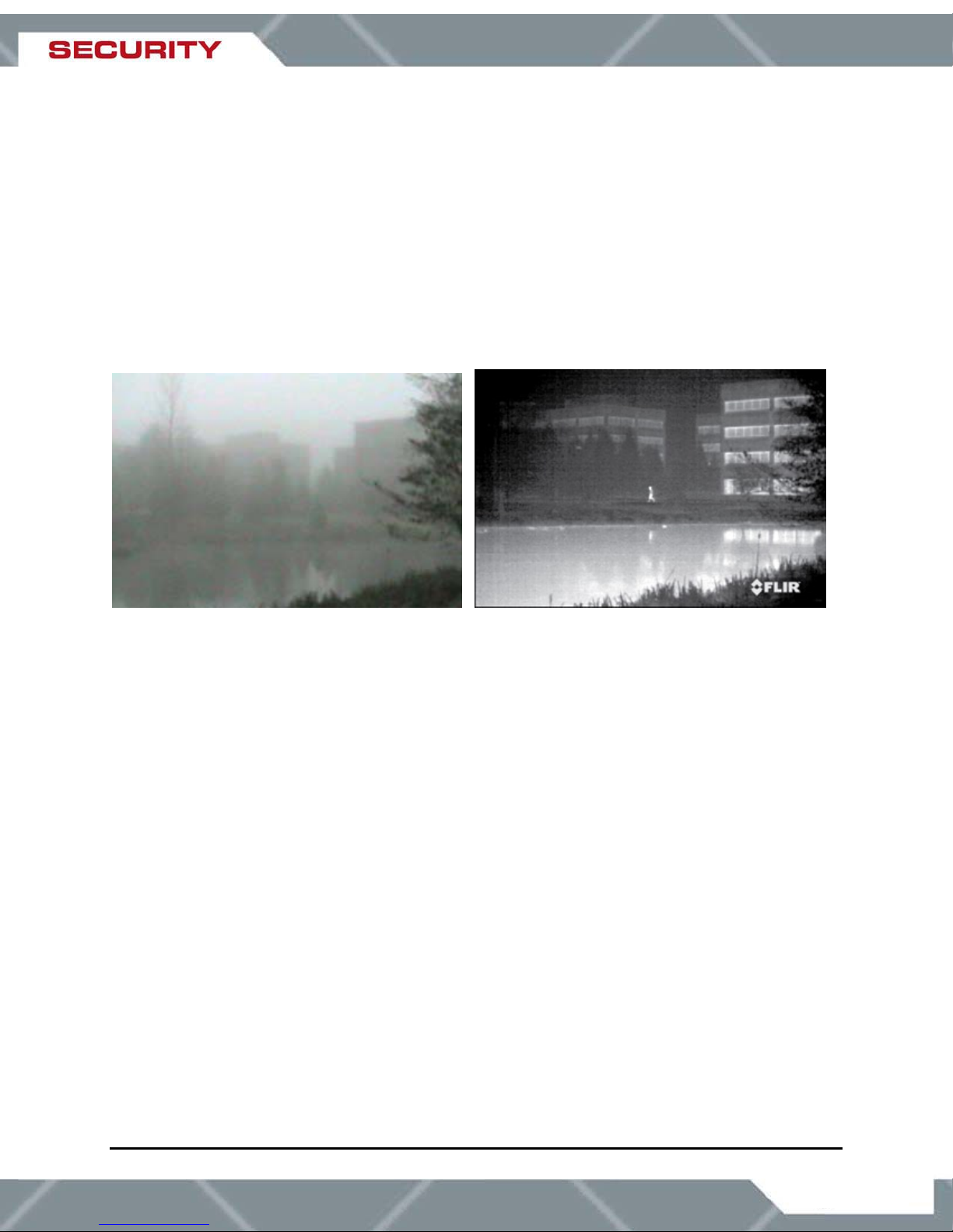
Figure 2 : Daylight camera on left; Thermal image on right
Observe that the image on the left from an ordinary daylight camera is obscured by fog; the
thermal image on the right provides clear details.
The SR-Series camera is designed for simple, intuitive installation and operation. Each camera
is based on FLIR’s widely-deployed uncooled microbolometer imaging core. All cameras include
FLIR’s advanced image processing techniques which deliver excellent contrast regardless of
scene dynamics. Unlike other night vision systems that require low amounts of light to generate
an image, the SR-Series thermal imagers need no light at all. The cameras are available with a
choice of lenses for short-, medium- and long-range surveillance capability.
SR-100
The 7° horizontal field of view of the SR-100 provides long range surveillance with high visual
acuity of distant targets. The camera features a motorized lens for adjustable focus. Like all SR-
series cameras, the SR-100 can be used on a fixed mount or pan/tilt platform and provides
crisp, clear thermal imagery in total darkness, light fog or smoke.
SR-100P
The SR-100P camera features a pressurized enclosure for added environmental protection and
the same focal length as the SR-100 camera (100mm, 7° FOV). This camera has a sealed and
pressurized outdoor enclosure that is designed to protect the camera and lens components in
adverse environmental conditions. The pressurized enclosure increases the camera reliability
and reduces the cost of maintenance.
427-0014-00-10 Revision 150 Copyright © 2007 FLIR Systems, Inc. 6
SR-50
Utilizing a 50mm lens, the SR-50 serves as a medium- to long-range surveillance camera and
provides a 14° HFOV. This focal length is widely deployed because it provides an even balance
between situational awareness and detailed perspective.
SR-35
The SR-35 camera features a focal length of 35mm, providing a short to medium field of view of
20° and is well-suited for short range threat detection in all circumstances.
SR-19
The SR-19 camera features a focal length of 19mm (36° HFOV) and, like the other SR-series
cameras, has a standard resolution Focal Plane Array (FPA) with 320 (H) x 240(V) pixels. It
gives you an extremely wide field of view, so that you can cover a large area and keep excellent
situational awareness.
VSR-6
The VSR-6 is an extremely affordable thermal imager with a focal length of 6.3mm (52°
Horizontal Field of View or HFOV). It features the same thermal imaging technology found in
many of FLIR’s most sophisticated security and surveillance systems, but is packaged for users
who have short-range security and surveillance as their primary application. The camera has a
standard resolution FPA that is windowed down to 160(H) x 120(V) pixels. The wide field of view
allows it to cover a large area and provide excellent situational awareness.
2.1 Advantages of Thermal Imaging
Originally developed for the military, thermal imaging cameras are now deployed in numerous
commercial applications where it is impractical or too expensive to use active illumination
(lights). It is perfect for wide-area surveillance in critical infrastructure or high-value residence
installations where lighting is unwelcome or impractical. The camera also provides improved
daytime surveillance in environments where traditional CCTV security camera performance
suffers, such as in shadows, backlit scenes or through foliage.
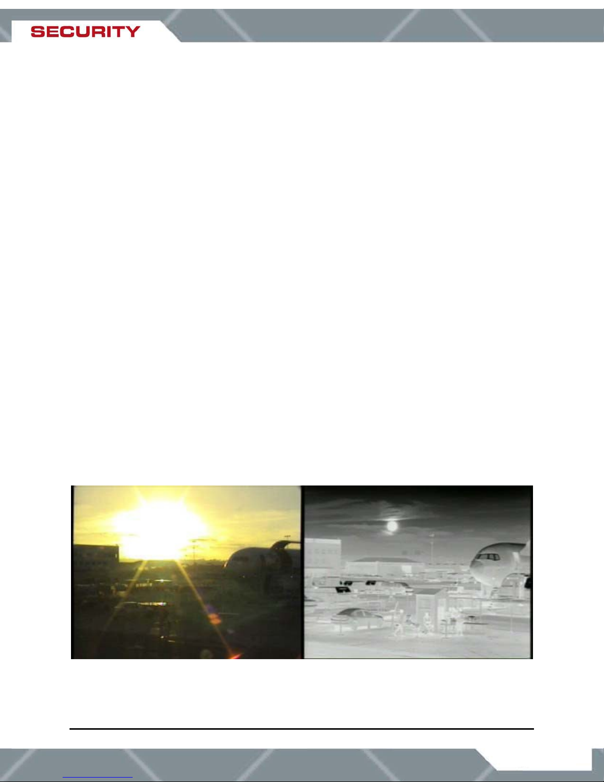
Figure 3: Backlit daylight camera on left; thermal image on right
427-0014-00-10 Revision 150 Copyright © 2007 FLIR Systems, Inc. 7
Observe that the setting sun in the backlit image on the left makes it difficult to discern any
objects of interest; the thermal image on the right is not affected by the bright sun and therefore
provides detail and contrast.
The SR-Series
is designed to be a drop-in replacement for current systems employing daylight
cameras. Initial setup of the system includes connecting power supply leads for the input power
and a BNC cable for monitoring output video. Optionally, a serial cable can be connected to
allow control of the camera settings and focus (focus control available on SR-100 and SR-100P
only, all other cameras are fixed focus).
2.2 Serial Remote Control
The SR-Series cameras have serial communication leads to connect for control of camera focus
and other features. Each camera is pre-configured at the factory to support either RS-232 or
RS-422 protocol (the serial protocol is not user-configurable). Users can control the camera
using devices that support the Pelco® D protocol
interface.
Camera Available Protocol
VSR-6 RS-232
SR-19 RS-232
SR-35 RS-232
SR-50 RS-232
SR-100 RS-422 Standard, RS-232 optional
SR-100P RS-422
The remote control can be used to operate the following functions or features:
Camera focus (SR-100 and SR-100P only)
Digital zoom (2X and 4X)
Selectable Automatic Gain Control (AGC) and Dynamic Detail Enhancement (DDE)
settings for optimization of video imagery
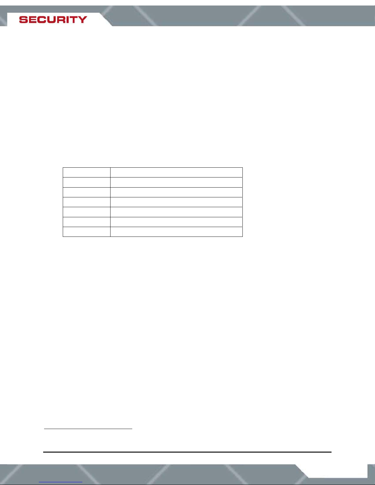
Camera Palette (also known as Polarity) - by default the White Hot palette is used;
alternatively the Black Hot palette displays warmer objects as black or dark rather than
white or light shades. Additional pseudo color palettes are available using the application
software supplied with the camera.
1
or through a Windows®-based graphical user
1
The "Pelco Digital Coaxitron" protocol is commonly known as the "Pelco D" protocol.
427-0014-00-10 Revision 150 Copyright © 2007 FLIR Systems, Inc. 8
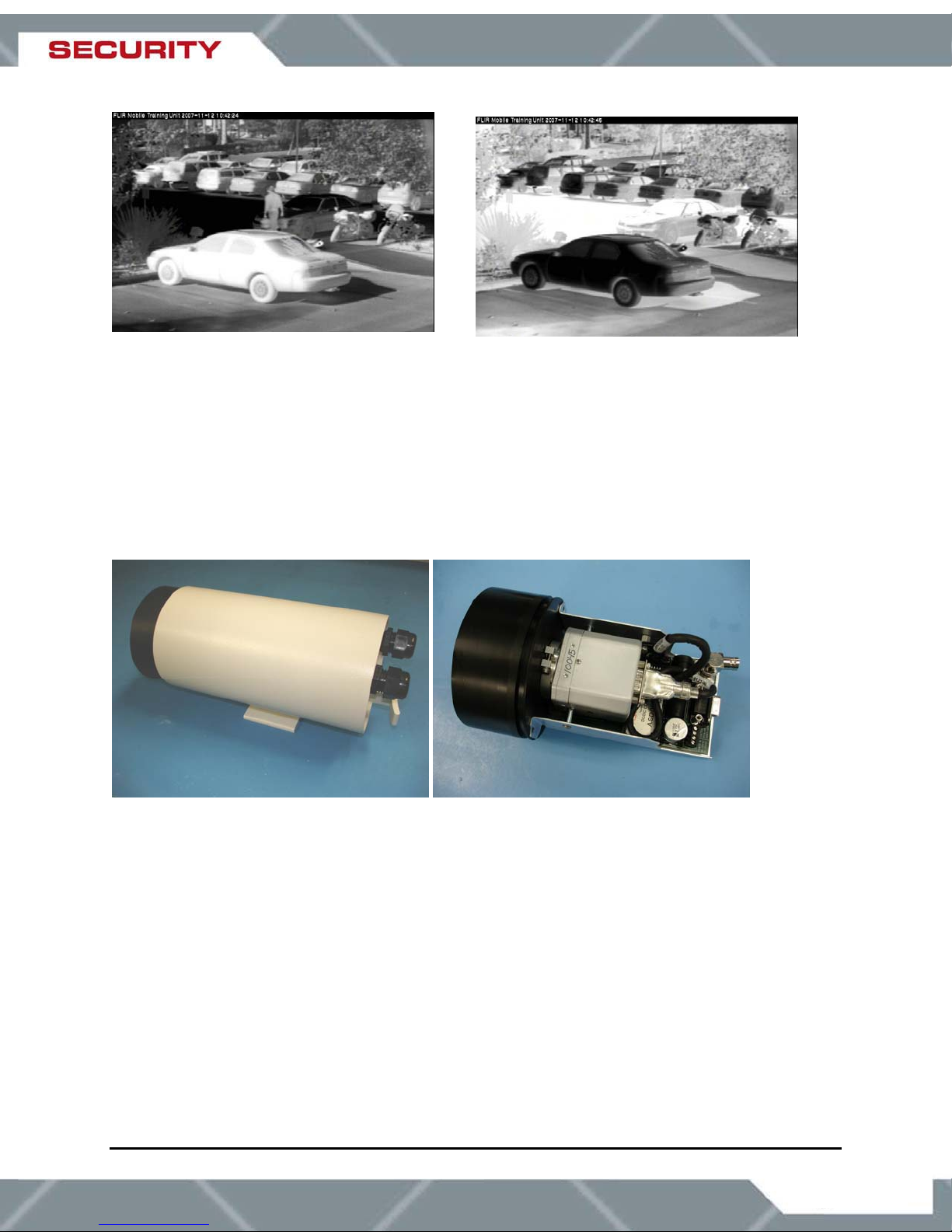
Figure 4: White Hot palette on left, Black Hot palette on right
2.3 Camera Enclosures
SR-Series cameras are packaged in environmental enclosures that meet IPX6 test standards.
Refer to section 0 SR-Series Camera Specifications for additional information. The camera’s
sun shroud around the enclosure helps regulate the camera temperature in direct-sun
installations. Each camera uses an athermalized lens and a lens heater to provide sharp
imagery in all temperature and weather conditions, ensuring a clear lens and high-quality
infrared video, even in extremely cold environments.
Figure 5: SR-35 Camera with and without the Environmental Enclosure
The SR-100P camera uses an enclosure that is sealed and pressurized for additional outdoor
protection in adverse conditions. The pressurized enclosure increases the camera reliability and
reduces the cost of maintenance. The enclosure is pressurized with dry nitrogen to prevent
impurities from contaminating the camera and lens components. The camera can be
pressurized in the field, and a pressure relief valve prevents overcharging of the enclosure.
427-0014-00-10 Revision 150 Copyright © 2007 FLIR Systems, Inc. 9
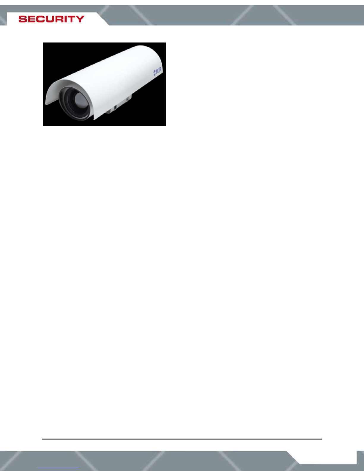
Figure 6: SR-100P with Sun Shroud
2.4 Package Contents
Refer to the Shipping Check List that is shipped with each camera for a description of the parts
and components that are included with the camera. If there is any discrepancy between the list
and the contents of your shipment, please contact FLIR Systems Customer Support
immediately using the contact information at the front of this manual.
427-0014-00-10 Revision 150 Copyright © 2007 FLIR Systems, Inc. 10
3.0 INSTALLATION
General installation information for all SR-series cameras is given below. While the general
installation procedure is the same for all cameras, there are some differences in the interfaces
and connections between various models. The instructions that are specific to certain models
are provided following the general procedures in the following sections:
4.0 SR-100 Installation
5.0 SR-100P Installation
6.0 VSR-6, SR-19, SR35, SR-50 Installation
If you have a question regarding installation or operation of your SR-Series camera, contact
FLIR Systems, Inc Customer Support, using the contact information at the front of this manual.
Check out our training web site (http://www.flir.com/training/
offered and to learn how you can become a FLIR-authorized Installer.
Caution! Be sure to leave the lens cap on during the installation process so the lens does not
get damaged or dirty. Do not forget to remove the lens cap once the installation is complete,
especially if the camera is being installed in a remote or difficult-to-reach location (such as on
top of a pole).
Do not expose the camera to direct sun for long periods without the sun shroud installed.
) to get information on courses
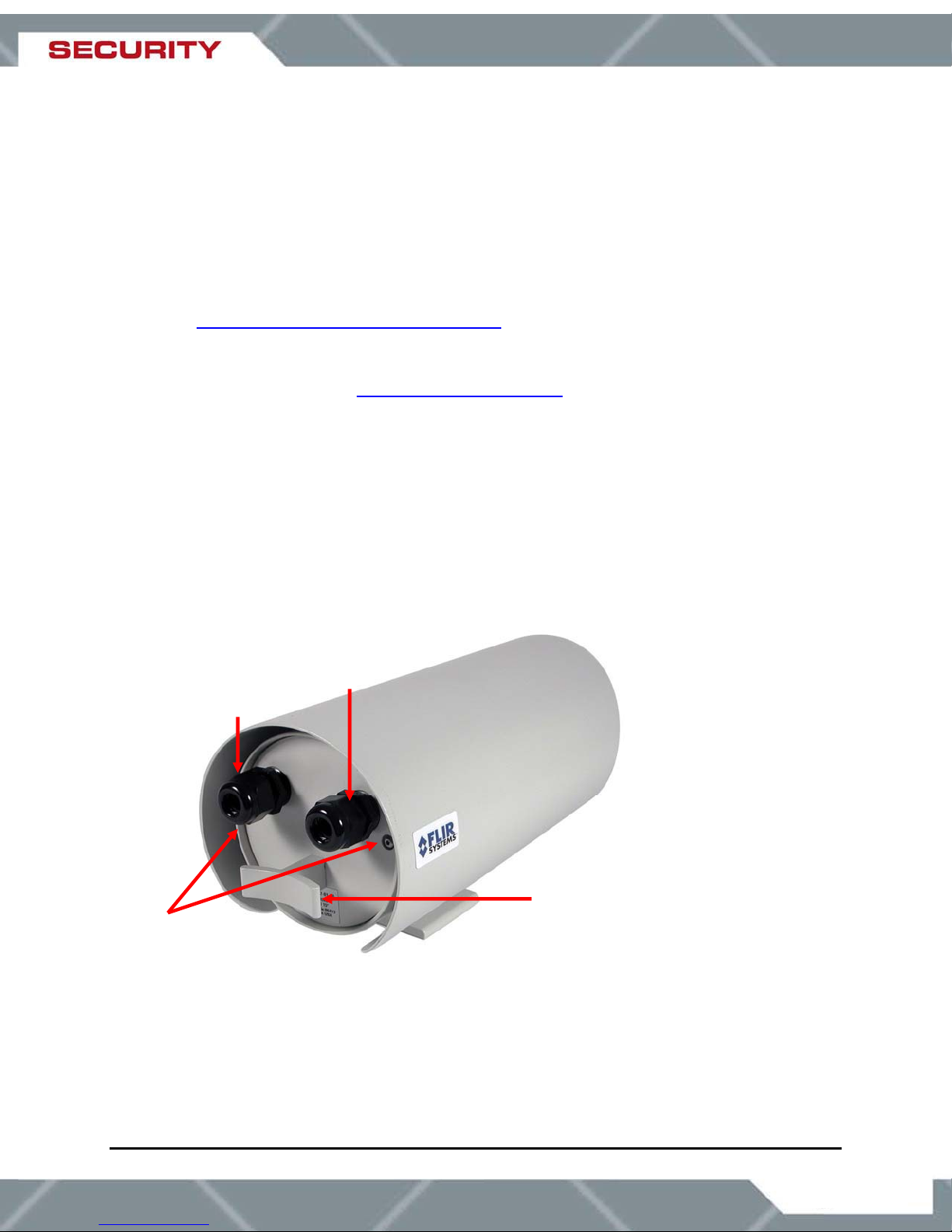
3.1 Accessing the Electrical Connections
Video cable
gland
Power cable
gland
Hex screws
Figure 7: Rear view of SR-Series camera
427-0014-00-10 Revision 150 Copyright © 2007 FLIR Systems, Inc. 11
“T” handle
)
In order to access the electrical connections for the VSR-6, SR-19, SR -35 and SR-50 cameras,
the camera must be removed from its enclosure. With the SR-100 camera, it is only necessary
to remove the rear of the enclosure (refer to section 4.0 SR-100 Installation). No disassembly is
required for the SR-100P pressurized camera.
The SR-Series provides electrical contacts in the form of screw-terminal jacks, allowing it to
receive 10-28 AWG tinned leads from the power supply and serial communication interface.
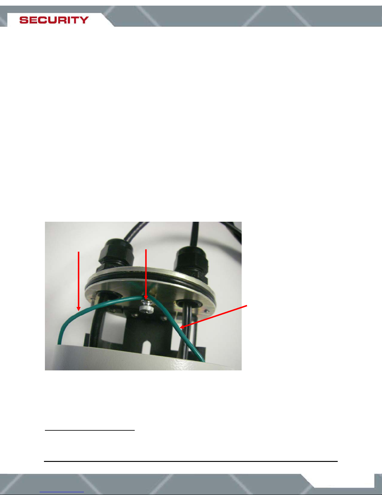
3.2 Ground Connection
The SR-Series cameras have grounding and surge protection to provide further immunity from
high current transients that can occur in installations that are subject to electrical storms and/or
nearby lightning events. In order to ensure CE and FCC compliance as well as to protect
against th
specific connection on the camera. Note: a ground connection to the exterior of the camera (for
example, to the mounting foot) is insufficient.
When the camera is shipped from FLIR, an internal ground wire (green) connects the interface
board to the Earth Ground Lug, located on the inside of the rear of the enclosure
disconnected during the installation, it must be reconnected. For proper installation, a ground
connection from an external Earth ground must be connected to the Earth Ground Lug as
shown in Figure 8: Earth Ground Connection. Typically the Earth ground connecti
of the power cable bundle.
ese high current events, installers are required to provide an Earth connection to a
2
. If is it
on will be part
Internal Ground
connection
Earth Ground
Lug
External Ground connection
(enters camera via power/serial
communications bundle
Figure 8: Earth Ground Connection
Caution! The camera must be installed according to industry-standard practices and local
electrical codes. Failure to properly connect the enclosure and the electrical interface board to
ground could result in damage to the camera and possible bodily injury.
2
On the SR-100P camera, the Earth Ground Lug is located on the outside of the rear of the enclosure.
Refer to section 5.0 SR-100P Installation for SR-100P installation details.
427-0014-00-10 Revision 150 Copyright © 2007 FLIR Systems, Inc. 12
 Loading...