

FLIR PTZ-35x140MS, SR-35x140MS Installation And Operation Manual
P
P
T
T
Z--
Z
3
3
5
5
x
x
1
1
4
4
0
0
M
M
S
S
S
S
IInnssttaallllaattiioonn aanndd O
R--
R
3
3
5
5
x
x
1
4
0
1
4
Oppeerraattiioonn
0
M
M
S
S
Maannuuaall
M
ThisdocumentiscontrolledtoFLIRTechnologyLevel1.Theinformationcontainedinthisdocument
pertainstoadualuseproductcontrolledforexportbytheExportAdministrationRegulations(EAR).FLIR
tradesecretscontainedhereinaresubjecttodisclosurerestrictionsasamatter
toUSlawisprohibited.USDepartmentofCommerceauthorizationisnotrequiredpriortoexportor
transfertoforeignpersonsorpartiesunlessotherwiseprohibited.
FLIR Systems, Inc. Aug 2011
70 Castilian Drive
Goleta, CA 93117
Phone: 888.747.FLIR (888.747.3547)
International: +1.805.964.9797 http:// www.flir.com
427-0011-00-10 Revision 140 Copyright © FLIR Systems, Inc. 1
oflaw.Diversioncontrary

FLIR Systems Inc.
70 Castilian Dr.
Goleta, CA 93117-3027
888.747.FLIR (888.747.3547)
Intl.: +1.805.964.9797
FAX 805 685-2711
www.flir.com
Document Number: 427-0011-00-10
Revision Number: 140
Date: August 2011
EXPORT RESTRICTIONS
The information contained in this document may be controlled for export purposes by the United States
Government. Diversion contrary to US law is prohibited. For more information, contact FLIR Systems, Inc.
This document and data disclosed herein or herewith is not to be reproduced, used, or disclosed in whole
or in part to anyone without the permission of FLIR Systems, Inc.
PROPRIETARY
The data in this publication shall not be disclosed without permission and shall not be duplicated, used, or
disclosed in whole or in part except to the extent provided in any contract of which this document is made
a part. This restriction does not limit the customer’s right to use information contained in this document if it
is obtainable from another source without restriction. The data subject to this restriction are contained in
all sheets of this document and related drawings and document specifications herein. FLIR reserves the
right to make changes to its products or specifications at any time, without notice, in order to improve
design or performance and to supply the best possible product.
COPYRIGHT
Copyright © 2011 FLIR Systems, Inc. All rights reserved. This publication, or any parts thereof, may not
be reproduced in any form without the express written permission of FLIR Systems, Inc.
FEDERAL COMMUNICATIONS COMMISSION REGULATORY INFORMATION
Modification of this device without the express authorization of FLIR Commercial Systems, Inc., may void
the user’s authority under the FCC Rules to operate this device.
Note: This equipment has been tested and found to comply with the limits for a Class A digital device,
pursuant to part 15 of the FCC Rules. These limits are designed to provide reasonable protection against
harmful interference when the equipment is operated in a commercial environment. This equipment
generates, uses, and can radiate radio frequency energy and, if not installed and used in accordance with
the instruction manual, may cause harmful interference to radio communications. Operation of this
equipment in a residential area is likely to cause harmful interference in which case the user will be
required to correct the interference at the user’s expense.
Shielded cables must be used to connect this device to other devices.
Warning – This is a Class A product. In a domestic environment this product may cause radio
interference in which case the user may be required to take adequate measures.
Pelco is a registered trademark of Pelco. Windows is a registered trademark of Microsoft Corporation.
427-0011-00-10 Revision 140 Copyright © FLIR Systems, Inc. 2

TABLE OF CONTENTS
1.0 WARNINGS AND CAUTIONS ...................................................................... 5
2.0 INTRODUCTION ........................................................................................... 6
2.1 Advantages of Thermal Imaging ......................................................................... 8
2.2 Camera Enclosures ............................................................................................ 9
2.3 Camera Control .................................................................................................. 9
2.4 Package Contents ............................................................................................ 10
3.0 INSTALLATION .......................................................................................... 11
3.1 Installation Overview ........................................................................................ 11
3.2 Camera Mounting ............................................................................................. 12
3.3 Camera Connections ........................................................................................ 13
3.4 Software Installation ......................................................................................... 15
3.5 Configuration and Control ................................................................................. 15
4.0 VERIFY CAMERA OPERATION ................................................................. 16
4.1 Bench Test Using FLIR Sensors Manager (FSM) ............................................ 17
5.0 CAMERA CONFIGURATION ...................................................................... 21
5.1 Web Configuration Overview ............................................................................ 21
5.2 Serial Communications ..................................................................................... 27
5.3 Configuration File ............................................................................................. 28
6.0 CAMERA OPERATION ............................................................................... 29
6.1 Thermal Imaging ............................................................................................... 29
6.2 Flat Field Correction (FFC) ............................................................................... 29
6.3 Pelco “D” Control .............................................................................................. 29
6.4 Pelco “D” Command List .................................................................................. 30
7.0 CARING FOR YOUR 35X140MS THERMAL CAMERA ............................. 30
7.1 Temperature ..................................................................................................... 31
7.2 Maintenance ..................................................................................................... 31
7.3 Troubleshooting Problems ................................................................................ 31
8.0 35X140MS CAMERA SPECIFICATIONS ................................................... 33
8.1 Environmental Requirements ........................................................................... 34
8.2 PTZ-35x140 PHYSICAL Dimensions ............................................................... 35
8.3 System Interface Cable Connector ................................................................... 40
9.0 DOCUMENT HISTORY ............................................................................... 42
10.0 USER CONTROLS FOR KBD300A ..................................................... 43
427-0011-00-10 Revision 140 Copyright © FLIR Systems, Inc. 3
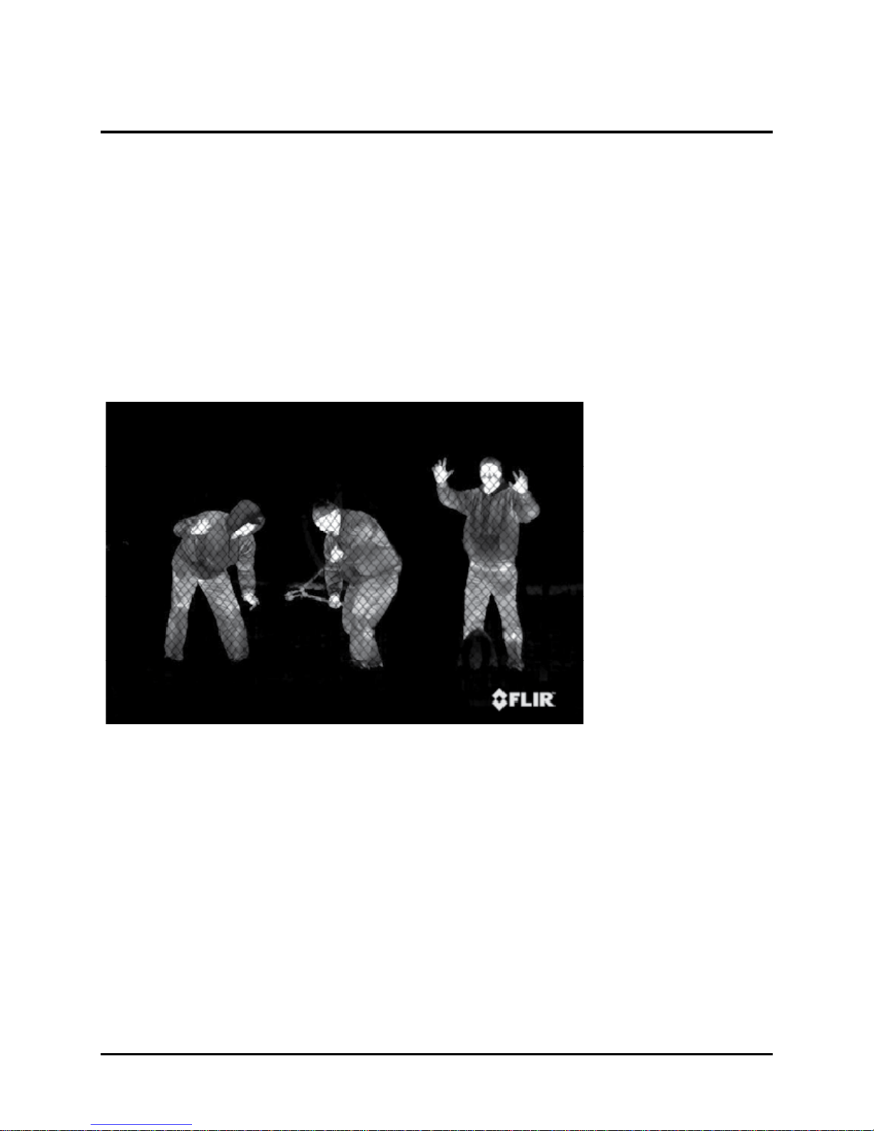
TABLE OF FIGURES
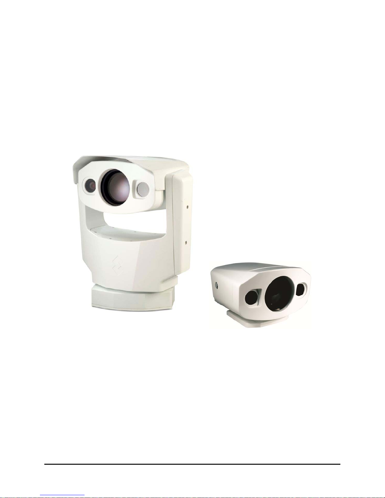
Figure 1-1: Thermal imaging allows 24/7 threat detection ............................................................ 4
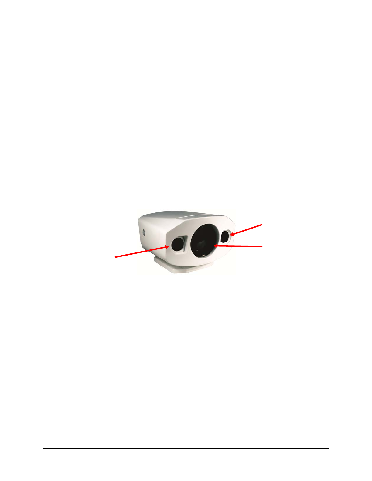
Figure 2-1: SR-35x140MS ............................................................................................................ 6
Figure 2-2: Foveal View (note the inset 5° field-of-view in both pictures ) .................................... 7
Figure 2-3 : Daylight camera on left; Thermal image on right ....................................................... 8
Figure 2-4: Backlit daylight camera on left; thermal image on right .............................................. 9
Figure 2-5: White Hot palette on left, Black Hot palette on right ................................................. 10
Figure 7-1: PTZ-35x140MS Dimension Drawing (inches) .......................................................... 36
Figure 8-1: SR-35x140MS Dimension Drawing (inches) ............................................................ 38
Figure 9-1: PTZ/SR-35x140MS Interface Cable Connector ....................................................... 40
Figure 9-2: Break-Out Connector Cable ..................................................................................... 41
Figure 1-1: Thermal imaging allows 24/7 threat detection
427-0011-00-10 Revision 140 Copyright © FLIR Systems, Inc. 4

1.0 WARNINGS AND CAUTIONS
Caution! This guide uses the term Caution! to indicate a potentially hazardous situation, which,
if not avoided, may result in bodily harm or injury, damage to the camera, or other property
damage.
Protect Your Investment
Do not disassemble the camera enclosure. Disassembly can cause permanent damage and
will void the warranty.
The camera should be installed by a trained professional according to local codes and industrystandard safe practices.
Proper ESD protocol should be followed while working inside the unit.
The camera is a precision optical instrument and should not be exposed to excessive shock or
vibration.
When not in use, put the camera in the Park position to protect the lenses. It is a good idea to
avoid pointing the system directly at extremely high-intensity radiation sources, such as the sun,
lasers, arc welders, etc. This warning applies whether or not the system is powered.
Great care should be used with your camera’s optics. They are delicate and can be damaged by
improper cleaning. Only clean the lens in the manner described in section 7.0 Caring for your
35x140MS Thermal Camera.
Legal Considerations
Camera and audio surveillance may be prohibited by laws that vary from country to country.
Check the laws in your local region before using this product for surveillance purposes.
Support
If you have questions that are not covered in this manual, or need service, contact FLIR
Customer Support at (805) 964-9797 for additional information prior to returning your 35x140MS
Thermal Camera. In the US, you can also reach FLIR Customer Support at (888) 747-FLIR
(747-3547).
All thermal imaging systems are subject to export control. Please contact FLIR for export
compliance information concerning your application or geographic area.
This equipment must be disposed of as electronic waste.
Contact your nearest FLIR Commercial Vision Systems, Inc. representative for instructions
on how to return the product to FLIR for proper disposal.
427-0011-00-10 Revision 140 Copyright © FLIR Systems, Inc. 5
2.0 INTRODUCTION
The PTZ-35x140MS and SR-35x140MS are high-resolution multi-sensor (MS) camera systems
designed specifically for the security market for medium- to long-range security applications.
Each model includes a sophisticated thermal imaging system that provides excellent night
visibility and situational awareness, even in absolute darkness, as well as a standard high
resolution low-light video camera
Each system includes a versatile, dual field-of-view thermal imaging system called Foveus, a
FLIR-patented innovation, which provides a high-resolution thermal image with a 5° view nested
inside a wider 20° view. This image presentation concept, derived from the same principles as
human vision, offers excellent situational awareness and long range threat detection,
simultaneously. Each system has two thermal imagers: a 35mm camera for wide-angle
surveillance, and a long-range 140mm camera, and the ability to continuously zoom between
the two fields of view.
This thermal imaging system is complimented with a high-resolution daylight camera, providing
optimal surveillance regardless of the time of day or lighting conditions. With the touch of a
button you can switch between the thermal imager and the daylight / low light camera. The
daylight camera provides up to 26x optical zoom. Displaying both the thermal image and the
daylight image at the same time is also possible via Ethernet.
1
, integrated into a compact weather enclosure.
35mm lens
Daylight
140mm lens
camera
Figure 2-1: SR-35x140MS
The SR-35x140MS is used for fixed-mount applications, or it can be integrated with a pan/tilt
mechanism. The camera provides crisp, clear thermal imagery in total darkness, light fog or
smoke. On the PTZ-35x140MS, this advanced payload is packaged in a precision pan/tilt
enclosure that will slew up to 120° per second. Each system provides standard video output
(PAL or NTSC format) that works with digital video recording devices, video motion detection
software or off-the-shelf video encoders.
Both 35x140MS camera systems have the performance of military-grade camera systems at a
fraction of the cost. Security operators can field them as portable stand-alone cameras, or
integrate them into a camera network. The cameras provide serial and analog connectivity for
existing legacy infrastructures using widely-deployed interface standards. Either system can be
integrated into IP Video security infrastructures using TCP/IP standards. The cameras support
network operation and control through the Nexus ™ architecture using FLIR Sensors Manager
(FSM) software or a third-party VMS. Video can be streamed over TCP/IP using FSM or a third
party video player.
1
The standard video camera is referred to in this manual generally as a daylight camera or
DLTV.
427-0011-00-10 Revision 140 Copyright © FLIR Systems, Inc. 6
The Foveal Concept
The PTZ-35x140MS and SR-35x140MS feature a completely new concept in image
presentation based on the foveal vision of the human eye. Foveal vision allows the operator to
enjoy a wide angle view for situational awareness while maintaining a high resolution area in the
center of the screen for object identification and tracking.
The PTZ-35x140MS and SR-35x140MS accomplish this with two independent thermal cameras
and a unique patented image processing technique that provides both the foveal imaging mode
as well as a continuous zoom between the wide and narrow fields of view.
The Foveus thermal imagery is provided as continually zoomed video from the wide 20°
horizontal field-of-view (from the 35mm lens) to the more narrow 5° field-of-view (from the
140mm lens). The thermal imagery is presented by blending the two thermal images to provide
high visual acuity in the critical 5° center area while simultaneously providing medium resolution
in the 20° situational awareness zone. This presentation is an application of the design of the
human eye, with the foveal region of the retina employing higher sensitivity than the peripheral
area, thus the moniker Foveus™.
When the system is zoomed out, the video output comes from the 20° field-of-view and the 5°
field-of-view disappears. After zooming in slightly, the wide 5° field-of-view appears as a small
inset window in the center. Continuing to zoom in causes the inset window to grow until it fills
the video screen, eliminating the wide field-of-view.
Figure 2-2: Foveal View (note the inset 5° field-of-view in both pictures)
The image on the left shows the wide overall perspective of the 20° field-of-view, and the
camera is partially zoomed in to show with the narrower field-of-view. The image on the right
shows the camera nearly fully zoomed in, and the 5° field-of-view dominates the image.
The 5° horizontal field-of-view of the 140mm lens provides long range surveillance with high
visual acuity of distant targets. The 35mm lens provides a short to medium field-of-view of 20°
and is well-suited for short range threat detection in all circumstances. The wide field-of-view
allows it to cover a large area and provide excellent situational awareness. And the patented
technology of FLIR allows continuous zoom between both fields of view.
427-0011-00-10 Revision 140 Copyright © FLIR Systems, Inc. 7
2.1 Advantages of Thermal Imaging
The 35x140MS camera is designed for simple, intuitive installation and operation. Each thermal
camera is based on FLIR’s widely-deployed uncooled microbolometer imaging core. All
cameras include FLIR’s advanced image processing techniques which deliver excellent contrast
regardless of scene dynamics. Unlike other night vision systems that require low amounts of
light to generate an image, the 35x140MS thermal imagers need no light at all.
The 35x140MS
setup of the system includes connecting power supply leads for the input power and BNC cable
for monitoring output video (one cable is used for both the thermal and daylight video). A serial
cable can be connected to allow control of the camera (pan, tilt, zoom, focus, and so on) and
modify camera settings, and an Ethernet port is available for integration into IP networks.
FLIR’s powerful thermal security cameras compliment and complete your security camera
network. They turn night into day, allowing you to see intruders invisible to the naked eye.
Thermal cameras create video images from infrared thermal energy (heat), and perform well at
night and day, in good weather and bad.
can be easily integrated with current systems employing daylight cameras. Initial
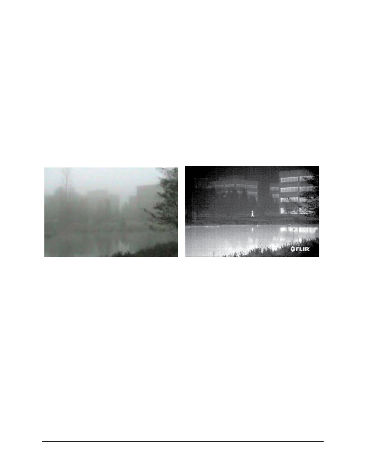
Figure 2-3 : Daylight camera on left; Thermal image on right
Under some environmental conditions, such as haze, or certain lighting conditions, such as
scenes with shadows, you will likely find that the thermal camera may outperform the daylight
camera, even during the day. Observe that the image above on the left from an ordinary
daylight camera is obscured by fog, while the thermal image on the right provides clear details.
Originally developed for the military, thermal imaging cameras are now deployed in numerous
commercial applications where it is impractical or too expensive to use active illumination
(lights). It is perfect for wide-area surveillance in critical infrastructure or high-value residence
installations where lighting is unwelcome or impractical. The camera also provides improved
daytime surveillance in environments where traditional CCTV security camera performance
suffers, such as in shadows, backlit scenes or through foliage.
427-0011-00-10 Revision 140 Copyright © FLIR Systems, Inc. 8
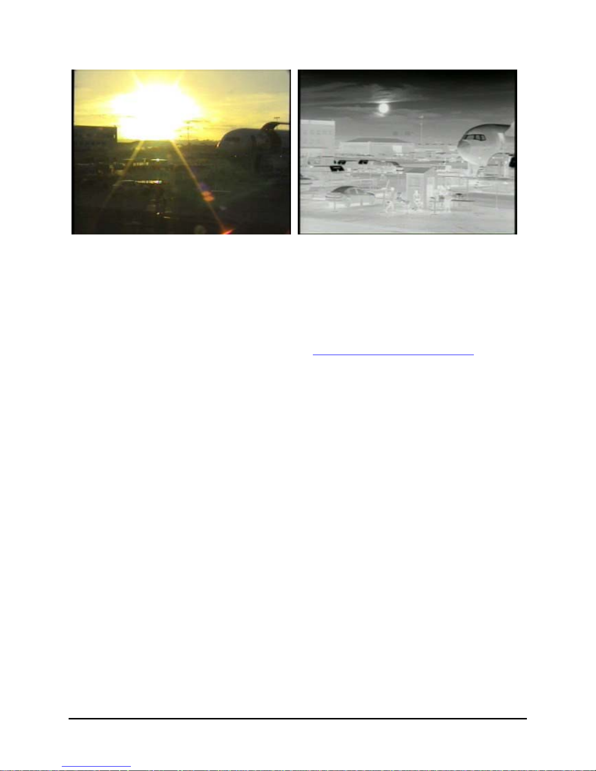
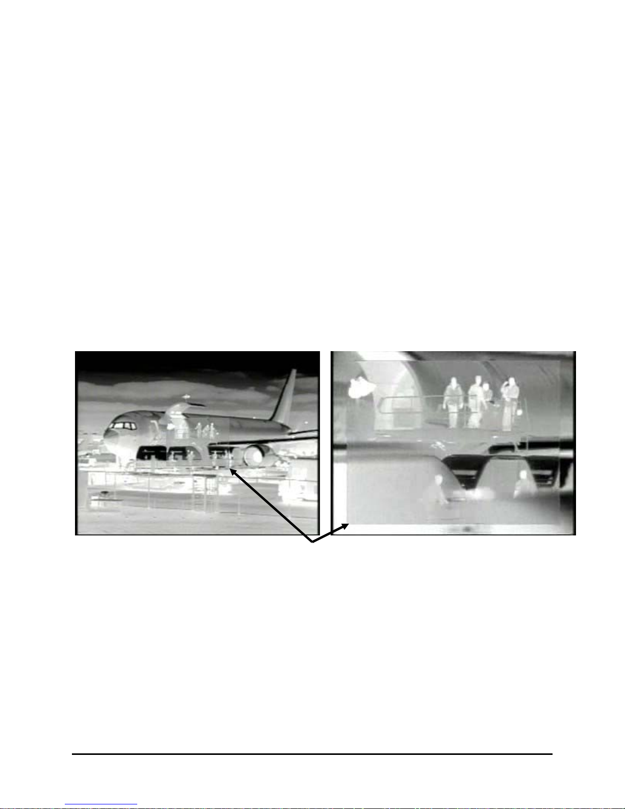
Figure 2-4: Backlit daylight camera on left; thermal image on right
Observe that the setting sun in the backlit image on the left makes it difficult to discern any
objects of interest; the thermal image on the right is not affected by the bright sun and therefore
provides detail and contrast.
2.2 Camera Enclosures
The PTZ-35x140MS and SR-35x140MS cameras are packaged in environmental enclosures
that meet IPX6 test standards. Refer to section 8.0 35x140MS Camera Specifications
additional specifications. The camera’s sun shroud around the enclosure helps regulate the
camera temperature in direct-sun installations. Each camera uses a lens heater to provide
sharp imagery in all temperature and weather conditions, ensuring a clear lens and high-quality
infrared video, even in extremely cold environments.
for
2.3 Camera Control
The 35x140MS cameras have serial communication leads for control of the camera utilizing RS422 protocol. Users can control the camera using devices that support the Pelco® “D” protocol.
The serial control is connected with a standard 9-pin connector (DB9) via the provided System
Cable.
The camera can also be attached to an IP network through the Ethernet interface and controlled
through the supplied FLIR Sensors Manager software running on your PC. The software allows
streaming video and allows multiple users to control and/or monitor the camera.
Either method for remote control can be used to operate the following functions or features:
Pan/Tilt (PTZ-35x140MS only) and Zoom
Camera focus
Toggle analog video output between the thermal camera and the daylight camera
Selectable Automatic Gain Control (AGC) and Dynamic Detail Enhancement (DDE)
settings for optimization of video imagery
Camera Palette (also known as Polarity) - by default the White Hot palette is used;
alternatively the Black Hot palette displays warmer objects as black or dark rather than
white or light shades. Additional pseudo color palettes are available using the application
software supplied with the camera.
Other controls specific to the thermal imager (refer to section 6.0 Camera Operation for
additional details on controlling the camera
427-0011-00-10 Revision 140 Copyright © FLIR Systems, Inc. 9
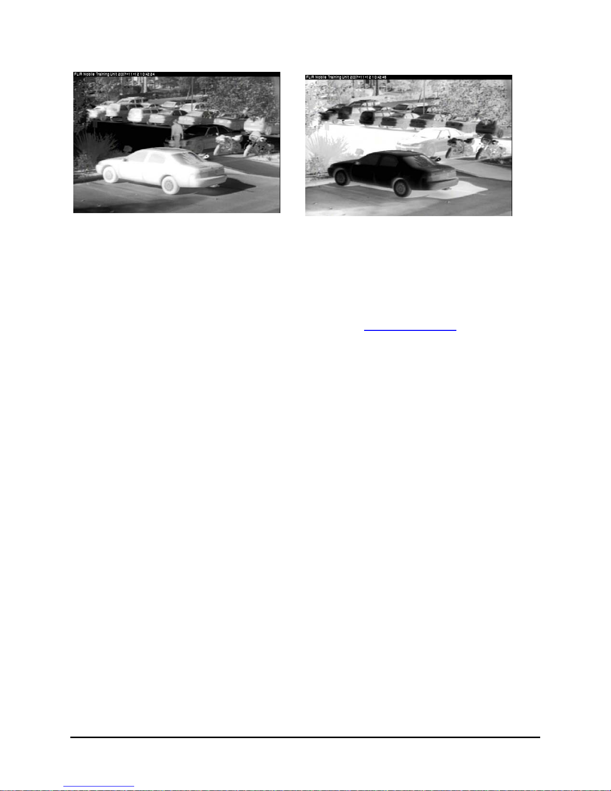
Figure 2-5: White Hot palette on left, Black Hot palette on right
2.4 Package Contents
Refer to the Shipping Check List that is shipped with each camera for a description of the parts
and components that are included with the camera. If there is any discrepancy between the list
and the contents of your shipment, please contact FLIR Systems Customer Support
immediately using the contact information at the front of this manual.
For a list of optional accessories, refer to the FLIR web site: http://www.flir.com/
.
427-0011-00-10 Revision 140 Copyright © FLIR Systems, Inc. 10
3.0 INSTALLATION
General installation information for both 35x140MS cameras is given below. If you have a
question regarding installation or operation of your 35x140MS camera, contact FLIR Systems,
Inc Customer Support, using the contact information at the front of this manual. Check out our
training web site (http://www.flir.com/training/
how you can become a FLIR-authorized Installer.
Caution! Be careful during the installation process so the lenses do not get damaged or dirty.
Do not forget to remove the protective adhesive sheet after the installation is complete.
Caution! Proper ESD protocol should be followed while working with the unit.
3.1 Installation Overview
Disassembly of the camera is not required for installation. Disassembling the camera can cause
permanent damage and will void the warranty.
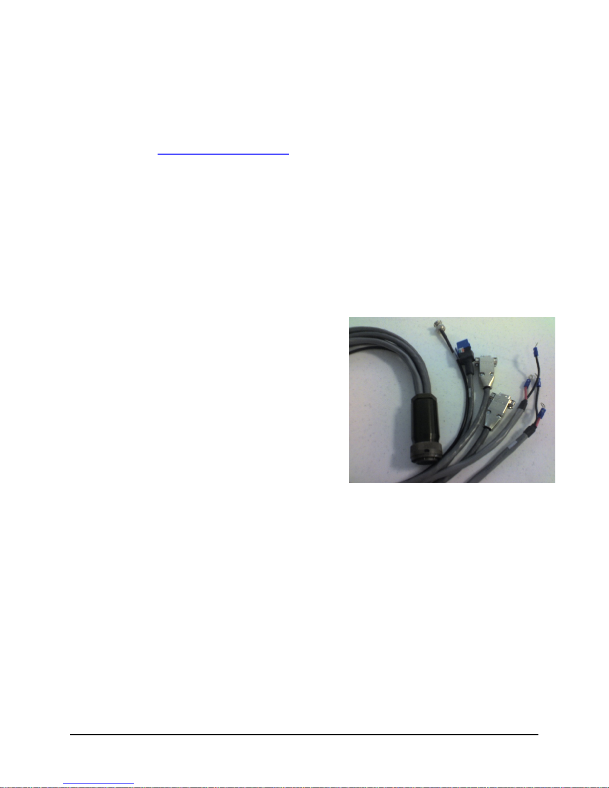
In most installations, the camera will be connected via a System Cable (P/N 308-0116-02) and a
Break-Out Connector Cable (P/N 308-0117-00). The breakout cable provides the following
connections (labels given in parentheses):
BNC for composite video (VIDEO P2)
RJ45 Ethernet (ETHERNET P5)
System power with 2 terminal rings (SYS PWR)
Pan/Tilt power with 2 terminal rings (PT PWR)
DB9 RS-422 for serial communications (USER
P3)
DB9 Maintenance connection, used for service
only (Maintenance P4), with termination plug
(termination plug is required)
Each breakout end of the cable (away from the
camera) must be protected from the weather.
Important!
When the Break-Out Connector Cable is used with the optional 40 ft System Cable,
connect the Ethernet to a switch or router using a twisted pair cable that does not exceed 2
meters.
) to get information on courses offered and to learn
427-0011-00-10 Revision 140 Copyright © FLIR Systems, Inc. 11
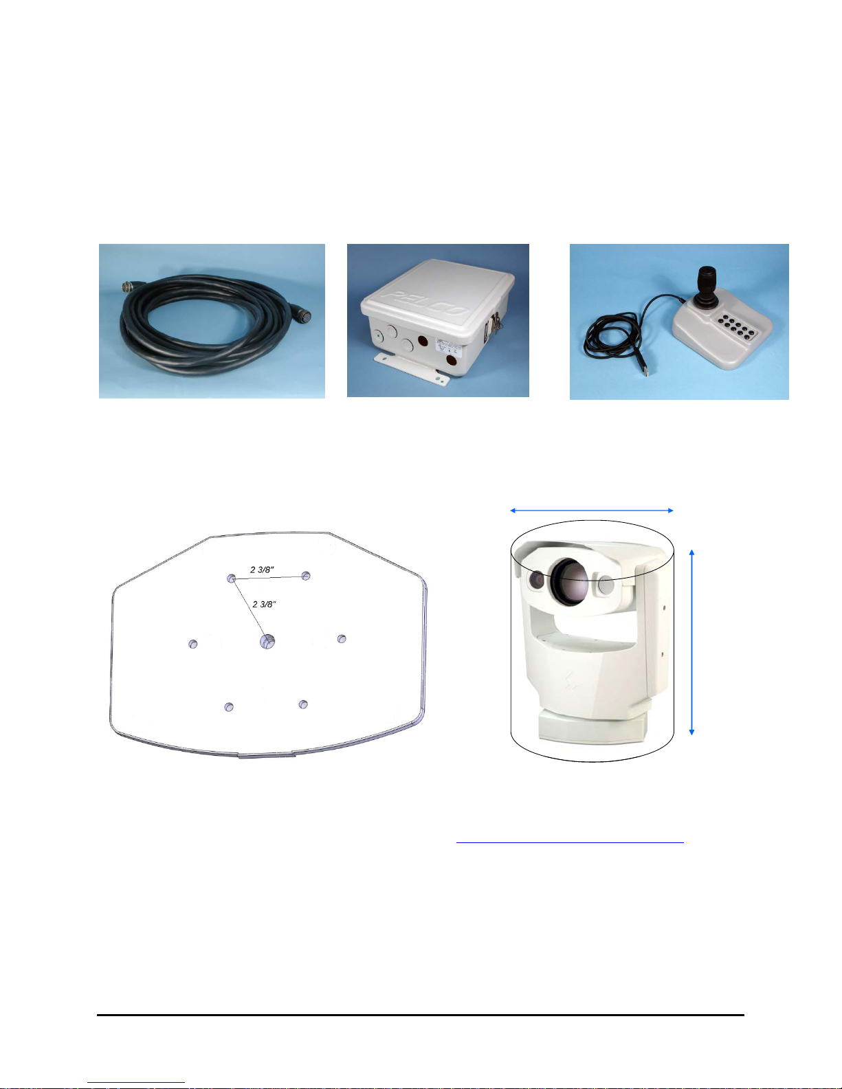
Optional Accessories
For installation purposes, the following optional accessories are available.
40 ft System Cable 308-0116-02
24VAC Power Supply 206-0004-01
Joystick 223-0017-00
3.2 Camera Mounting
Firmly secure the camera to a designated frame or structure capable of supporting the camera,
using the mounting pattern shown below. For the PTZ-35x140MS, be sure to allow for device
travel by providing a clearance cylinder of 15.5” (39.37cm) diameter and 22” (55.88cm) height.
Mounting the SR-35x140MS camera is accomplished using the six 1/4-20 tripod mount holes or
the single 3/8-16 central mount hole on the underside of the enclosure foot. The dimensions of
the camera mounting foot are provided in section 8.0 35x140MS Camera Specifications
reference.
The SR-35x140MS enclosure can be mounted to a wall mount, ceiling or pedestal mount, or a
pan/tilt mechanism on a wall or ceiling. Refer to the manufacturer’s documentation
accompanying the fixed or pan/tilt mount for more information regarding installation and
mounting.
427-0011-00-10 Revision 140 Copyright © FLIR Systems, Inc. 12
for
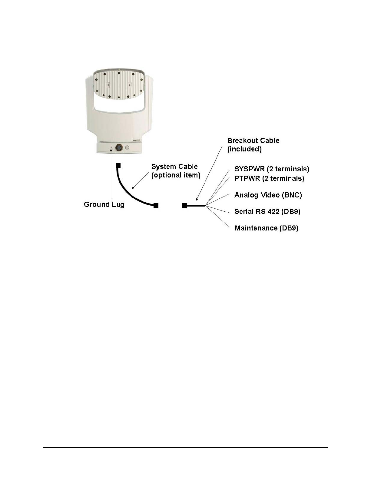
3.3 Camera Connections
Connect the sealed System Cable to the connection on the camera base shown above. Then
attach the other end of the System Cable to the Break-Out Connector Cable. The far end of the
breakout cable must be protected from the weather.
Ground Connection
The 35x140MS cameras have grounding and surge protection to provide limited immunity from
high current transients that can occur in installations subject to electrical storms and/or nearby
lightning events. In order to ensure CE and FCC compliance as well as to protect against
these high current events, installers are required to provide an Earth connection to a specific
connection on the camera (the ground lug indicated above). Note: a ground connection to the
exterior of the camera (for example, to the mounting foot) is insufficient.
Caution! The camera must be installed according to industry-standard practices and local
electrical codes. Failure to properly connect the enclosure and the electrical interface board to
ground could result in damage to the camera and possible bodily injury.
Input Power
The 35x140MS cameras operate on 24Volts (nominal) power, AC or DC. The camera has
separate power connections for the pan/tilt mechanism and the rest of the system. Provide
either 24+/-10% VAC rms (50/60Hz) or 24+/-10% VDC directly to the connections labeled
“PTPWR” and “SYSPWR” on the break-out cable.
427-0011-00-10 Revision 140 Copyright © FLIR Systems, Inc. 13
 Loading...