

S
S
R--
R
P
P
T
T
T
T
h
h
err
e
m
m
all
a
C
C
a
a
m
m
err
e
a
a
IInnssttaallllaattiioonnaannddO
Oppeerraattiioonn
Maannuuaall
M
ThermalVideo.com
Your Source for Modern
Thermal Imaging Systems
P.O. BOX 4242
Middletown, NY 10941
427-0027-01-10 Rev. 100 © 2009 FLIR Systems, Inc. Page 1 of 21
PH: + 1 888 919 2263
PH Intl: + 1 845 343 4077
FX: + 1 845 343 4299
support@thermalvideo.com
www.thermalvideo.com
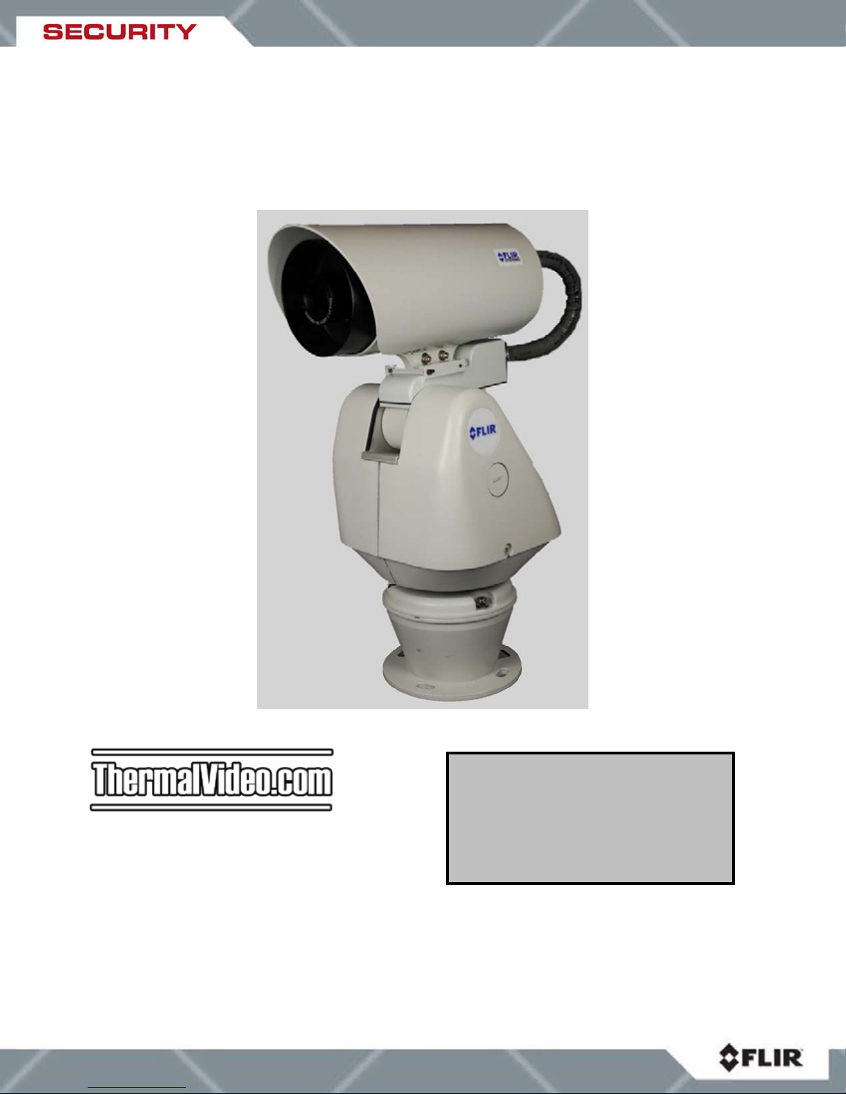
Camera Models
SR-100 PT SR-50 PT
SR-35 PT SR-19 PT
ThermalVideo.com
Your Source for Modern
Thermal Imaging Systems
P.O. BOX 4242
Middletown, NY 10941
PH: + 1 888 919 2263
PH Intl: + 1 845 343 4077
FX: + 1 845 343 4299
support@thermalvideo.com
www.thermalvideo.com
427-0027-01-10 Rev. 100
Date: May 29, 2009
Revision Date Notes
100 05/29/2009 Initial release
EXPORT RESTRICTIONS
This document is controlled to FLIR Technology Level 2. The information contained in this
document pertains to a dual use product controlled for export by the Export Administration
Regulations (EAR). FLIR trade secrets contained herein are subject to disclosure restrictions as
a matter of law. Diversion contrary to US law is prohibited. US Department of Commerce
authorization is not required prior to export or transfer to foreign persons or parties unless
otherwise prohibited.
427-0027-01-10 Rev. 100 © 2009 FLIR Systems, Inc. Page 2 of 21

Table of Contents
WARNINGS AND CAUTIONS......................................................................................................4
Protect Your Investment........................................................................................................4
References ............................................................................................................................4
Introduction...................................................................................................................................5
SR-PT Camera Models.............................................................................................................5
Camera..................................................................................................................................6
Description.............................................................................................................................6
SR-100 PT.............................................................................................................................6
SR-50 PT...............................................................................................................................6
SR-35 PT...............................................................................................................................6
SR-19 PT...............................................................................................................................6
Serial Remote Control...............................................................................................................6
Installation.....................................................................................................................................7
Ground Connection................................................................................................................7
Accessing the Electrical Connections .......................................................................................8
Power and Serial connections.................................................................................................10
Cable Leads.........................................................................................................................10
Input Power..........................................................................................................................10
SR-100 PT Connections......................................................................................................11
SR-19, SR-35, SR-50 Connections.....................................................................................12
Assembly of Camera to Pan/Tilt base.....................................................................................13
Mounting the SR-PT Camera......................................................................................................14
Camera Operation ......................................................................................................................17
IR Functions................................................................................................................................17
Operational Temperatures..........................................................................................................17
APPENDIX..................................................................................................................................18
427-0027-01-10 Rev. 100 © 2009 FLIR Systems, Inc. Page 3 of 21

WARNINGS AND CAUTIONS
Warning! This guide uses the term Warning! to indicate a potentially hazardous situation,
which, if not avoided, may result in bodily harm or injury, damage to the camera, or other
property damage.
Protect Your Investment
The camera should be installed by a trained professional according to local codes and industrystandard safe practices.
Proper ESD protocol should be followed while working inside the unit.
The camera is a precision optical instrument and should not be exposed to excessive shock or
vibration.
Avoid pointing the system directly at extremely high-intensity radiation sources, such as the sun,
lasers, arc welders, etc. This warning applies whether or not the system is powered.
Great care should be used with your camera’s optics. They are delicate and can be damaged by
improper cleaning. Only clean the lens in the manner described in SR-Series user manual.
References
For additional information regarding installation of the SR camera, please refer to the SR-Series
Installation and Operation Manual (Document number 427-0014-00-10).
If you have a question regarding installation or operation of your SR-PT camera, contact Thermal
Video.com, Customer Support, using the contact information at the front of this manual. Check
out our web site at ( http://www.thermalvideo.com
to learn how you can become a FLIR-authorized Installer.
Take care during installation to avoid scratching the camera lens. Do not expose the camera to
direct sun for long periods without the sun shroud installed.
Important! All thermal imaging systems are subject to export control. Please contact FLIR
for export compliance information concerning your application or geographic area.
) to get information on courses offered and
427-0027-01-10 Rev. 100 © 2009 FLIR Systems, Inc. Page 4 of 21
Introduction
The SR-PT Thermal Camera you have purchased is a sophisticated
thermal imaging camera that provides excellent night visibility and
situational awareness, even in absolute darkness. The camera has a
standard video output that works with digital video recording devices,
video motion detection software or off-the-shelf video encoders.
FLIR’s powerful SR-PT thermal security cameras compliment and
complete your security camera network. They turn night into day, allowing
you to see intruders invisible to the naked eye. SR-PT cameras create
video images from infrared thermal energy (heat), and perform well at
night and day, in good weather and bad. The SR Series thermal
surveillance camera system is intended for various commercial and
industrial applications, including security and surveillance.
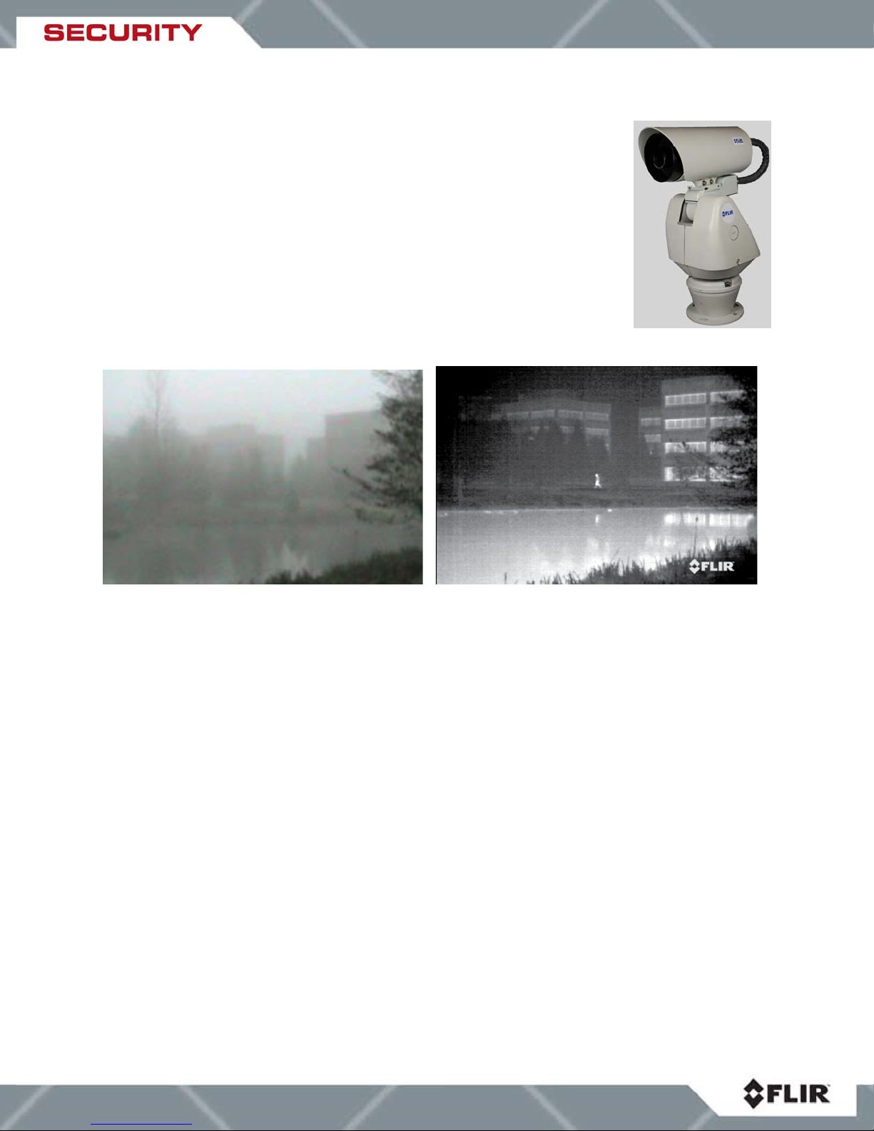
Figure 0-1 : Daylight camera on left; Thermal image on right
Observe that the image on the left from an ordinary daylight camera is obscured by fog; the
thermal image on the right provides clear details.
The SR-PT camera is designed for simple, intuitive installation and operation. Each camera is
based on FLIR’s widely-deployed uncooled microbolometer imaging core. All cameras include
FLIR’s advanced image processing techniques which deliver excellent contrast regardless of
scene dynamics. Unlike other night vision systems that require low amounts of light to generate
an image, the SR-PT thermal imagers need no light at all.
SR-PT Camera Models
The cameras are available with a choice of lenses for short-, medium- and long-range
surveillance capability.
427-0027-01-10 Rev. 100 © 2009 FLIR Systems, Inc. Page 5 of 21

Camera Description
SR-100 PT
SR-50 PT
SR-35 PT
SR-19 PT
The 7° horizontal field of view of the SR-100 provides long range surveillance
with high visual acuity of distant targets. The camera features a motorized lens
for adjustable focus. Like all SR-PT cameras, the SR-100 provides crisp, clear
thermal imagery in total darkness, light fog or smoke.
Utilizing a 50mm lens, the SR-50 serves as a medium-range surveillance
camera and provides a 14° HFOV. This focal length is widely deployed because
it provides an even balance between situational awareness and detailed
perspective.
The SR-35 camera features a focal length of 35mm, providing a short to
medium field of view of 20° and is well-suited for short range threat detection in
all circumstances.
The SR-19 camera features a focal length of 19mm (36° HFOV) and, like the
other SR-PT cameras, has a standard resolution Focal Plane Array (FPA) with
320x240 pixels (320x256 PAL format). It gives you an extremely wide field of
view, so that you can cover a large area and keep excellent situational
awareness.
Serial Remote Control
The SR-PT cameras support serial communication for control of camera pan/tilt, focus (SR-100
PT only) and other features. Each camera is pre-configured at the factory to support RS-422
protocol. Users can control the camera with devices that support the Pelco® D protocol. Such
devices allow the user to operate the following functions or features:
• Camera pan (360° continuous pan)
• Camera tilt (from +33° to -83° azimuth)
• Camera focus (SR-100 only)
• Digital zoom (2X)
• Camera Palette (also known as Polarity) - by default the White Hot palette is used;
alternatively the Black Hot palette displays warmer objects as black or dark rather than
white or light shades. Additional pseudo color palettes are available using the application
software supplied with the camera.
427-0027-01-10 Rev. 100 © 2009 FLIR Systems, Inc. Page 6 of 21
Installation
The SR-PT Thermal Imaging camera is packaged in a separate box from the pan/tilt base. The
wires from the base will need to be connected to the camera through an opening in the back of
the camera and the camera will need to be installed on the top of the pan/tilt base. Then the
connections to the assembled unit are made.
Ground Connection
The SR-PT cameras have grounding and surge protection to provide further immunity from high
current transients that can occur in installations that are subject to electrical storms and/or
nearby lightning events. In order to ensure CE and FCC compliance as well as to protect
against these high current events, installers are required to provide an Earth connection to a
specific connection on the camera assembly. Note: a ground connection to the exterior of the
camera (for example, to the mounting foot) is insufficient.
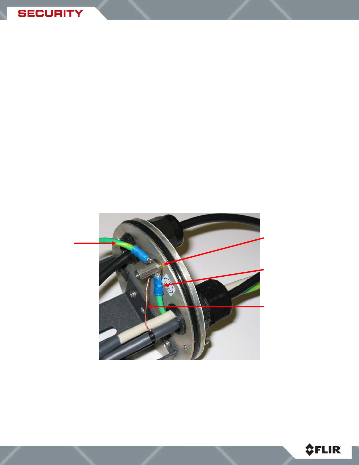
When the camera is shipped from FLIR, an internal ground wire (green) connects the interface
board to the Earth Ground Lug, located on the inside of the rear of the enclosure. If is it
disconnected during the installation, it must be reconnected. For proper installation, a ground
connection from an external Earth ground must be connected to the Earth Ground wire on the
pan/tilt base, and from the pan/tilt base to the Earth Ground Lug inside the rear cover of the
camera. Typically the Earth ground connection will be part of the power cable bundle.
Internal Ground
connection
Earth Ground
Lug
External Chassis
Ground connection
Power Supply
shield/drain wire
Figure 1: Earth Ground Connection
427-0027-01-10 Rev. 100 © 2009 FLIR Systems, Inc. Page 7 of 21
 Loading...