

FLIR Raymarine gS Series, gS95, gS165, gS165 inverted, gS195 Installation Instructions Manual
...Page 1

gS SERIES
INSTALLATION
INSTRUCTIONS
English
Date: 08-2015
Document number: 87248-2-EN
© 2015 Raymarine UK Limited
Page 2

Page 3

Trademarkandpatentsnotice
Raymarine,Tacktick,ClearPulse,Truzoom,HSB,SeaT alk,SeaT alk
hs
,SeaTalk
ng
,Micronet,Raytech,
GearUp,MarineShield,Seahawk,Autohelm,Automagic,andVisionalityareregisteredorclaimed
trademarksofRaymarineBelgium.
FLIR,DownVision,SideVision,Dragony,Instalert,InfraredEverywhere,andTheWorld’sSixth
SenseareregisteredorclaimedtrademarksofFLIRSystems,Inc.
Allothertrademarks,tradenames,orcompanynamesreferencedhereinareusedforidenticationonly
andarethepropertyoftheirrespectiveowners.
Thisproductisprotectedbypatents,designpatents,patentspending,ordesignpatentspending.
FairUseStatement
Youmayprintnomorethanthreecopiesofthismanualforyourownuse.Youmaynotmakeanyfurther
copiesordistributeorusethemanualinanyotherwayincludingwithoutlimitationexploitingthemanual
commerciallyorgivingorsellingcopiestothirdparties.
Softwareupdates
Important:ChecktheRaymarinewebsiteforthelatestsoftwarereleasesforyourproduct.
www.raymarine.com/software
Producthandbooks
ThelatestversionsofallEnglishandtranslatedhandbooksareavailabletodownloadinPDFformatfromthewebsite
www.raymarine.com.
Pleasecheckthewebsitetoensureyouhavethelatesthandbooks.
Copyright©2015RaymarineUKLtd.Allrightsreserved.
ENGLISH
Documentnumber:87248-2
Date:08-2015
Page 4

Page 5

Contents
Chapter1Importantinformation..........................7
CertiedInstallation.....................................................7
Productoperationinhightemperatures.........................7
PoweroverEthernet(PoE)...........................................8
TFTDisplays...............................................................9
Wateringress..............................................................9
Disclaimers.................................................................9
RFexposure...............................................................9
FCC............................................................................9
ComplianceStatement(Part15.19)..............................9
FCCInterferenceStatement(Part15.105(b))...............9
IndustryCanada........................................................10
IndustryCanada(Français)........................................10
Japaneseapprovals...................................................10
Declarationofconformity............................................10
Productdisposal........................................................10
Pixeldefectpolicy......................................................10
Warrantyregistration..................................................11
IMOandSOLAS........................................................11
Technicalaccuracy....................................................1 1
Chapter2Documentandproduct
information...........................................................13
2.1Documentinformation..........................................14
2.2Productdocumentation.........................................14
2.3Documentillustrations..........................................15
2.4Productoverview.................................................15
2.5LightHouseMFDOperationinstructions.................16
Chapter3Planningtheinstallation...................17
3.1Systemintegration...............................................18
3.2Installationchecklist.............................................24
3.3Multipledatasources(MDS)overview...................24
3.4Identifyingyourdisplayvariant..............................25
3.5Networkingconstraints.........................................25
3.6Systemprotocols.................................................26
3.7Datamaster.........................................................27
3.8Partssupplied......................................................28
3.9T oolsrequiredforinstallation.................................29
3.10Selectingalocation............................................29
Chapter4Cablesandconnections....................33
4.1Generalcablingguidance.....................................34
4.2gS95/gS125/gS165Connections
overview...................................................................35
4.3gS195connectionsoverview.................................35
4.4Poweranddata(combined)connection.................36
4.5PoweroverEthernet(PoE)...................................38
4.6Cardreaderconnection........................................38
4.7Auxiliaryalarmconnection....................................39
4.8SeaTalk
4.9NMEA2000connection........................................40
4.10SeaTalkconnection............................................41
ng®
connections.......................................39
4.11NMEA0183connection—Power/NMEA/Video
cable.........................................................................41
4.12Gigabitnetworking.............................................42
4.13Sonarmoduleconnection...................................43
4.14Radarnetworkconnection..................................44
4.15GNSS/GPSconnection.....................................46
4.16AISconnection...................................................47
4.17Fastheadingconnection......................................47
4.18Keypadnetworkconnection................................48
4.19Weatherreceiverconnection...............................48
4.20Videoconnection—composite...........................49
4.21Camera(Video/Alarm)connection.......................49
4.22HDMIvideooutput.............................................50
4.23IPCameraconnection........................................50
4.24HD-SDIconnection(gS195)................................51
4.25Thermalcameraconnection................................52
4.26Fusionnetworkconnection.................................54
4.27FusionNMEA2000connection...........................54
4.28Mediaplayerconnection.....................................55
4.29Raymarinemobileappconnection.......................55
4.30Bluetoothremotecontrolconnection....................56
Chapter5Mounting.............................................57
5.1Bracketmountingholelocations............................58
5.2Mountingsurfacerequirements.............................58
5.3Flushmountingthedisplay...................................59
5.4Flushmountingthecardreader.............................60
5.5Surfacemountingthedisplay................................61
5.6Surfacemountingthecardreader.........................62
Chapter6Maintainingyourdisplay...................63
6.1Serviceandmaintenance.....................................64
6.2Productcleaning..................................................64
Chapter7Troubleshooting.................................65
7.1Troubleshooting...................................................66
7.2Poweruptroubleshooting.....................................67
7.3Radartroubleshooting..........................................68
7.4GPStroubleshooting............................................69
7.5Sonartroubleshooting..........................................70
7.6Sonarcrosstalkinterference.................................73
7.7Thermalcameratroubleshooting...........................75
7.8Systemdatatroubleshooting.................................77
7.9Videotroubleshooting...........................................78
7.10Wi-Fitroubleshooting..........................................79
7.11Bluetoothtroubleshooting....................................80
7.12T ouchscreentroubleshooting..............................81
7.13T ouchscreenalignment.......................................82
7.14Miscellaneoustroubleshooting............................83
Chapter8Technicalspecication......................85
8.1T echnicalspecication..........................................86
Chapter9Technicalsupport..............................89
5
Page 6

9.1Raymarineproductsupportandservicing..............90
9.2Learningresources..............................................91
9.3Third-partysupport...............................................91
Chapter10Sparesandaccessories..................93
10.1gSSeriesaccessories........................................94
10.2gSSeriesspares................................................94
10.3Networkhardware..............................................95
10.4Networkcableconnectortypes............................95
10.5RayNettoRayNetcablesandconnectors...........96
10.6Networkcabletypes...........................................98
10.7SeaT alk
10.8SeaT alk
10.9SeaT alkaccessories.........................................100
ng
cablingcomponents............................98
ng
cablesandaccessories.......................99
6
gSSeriesinstallationinstructions
Page 7
Chapter1:Importantinformation
CertiedInstallation
Raymarinerecommendscertiedinstallationbya
Raymarineapprovedinstaller.Acertiedinstallation
qualiesforenhancedproductwarrantybenets.
ContactyourRaymarinedealerforfurtherdetails,
andrefertotheseparatewarrantydocumentpacked
withyourproduct.
Warning:FCCWarning(Part15.21)
Changesormodicationstothis
equipmentnotexpresslyapprovedin
writingbyRaymarineIncorporatedcould
violatecompliancewithFCCrulesand
voidtheuser’sauthoritytooperatethe
equipment.
Warning:Radartransmission
safety
Warning:Productinstallationand
operation
•Thisproductmustbeinstalledand
operatedinaccordancewiththe
instructionsprovided.Failuretodoso
couldresultinpersonalinjury,damage
toyourvesseland/orpoorproduct
performance.
•Raymarinerecommendscertied
installationbyaRaymarineapproved
installer.Acertiedinstallationqualies
forenhancedproductwarrantybenets.
ContactyourRaymarinedealerfor
furtherdetails,andrefertotheseparate
warrantydocumentpackedwithyour
product.
Warning:Potentialignitionsource
ThisproductisNOTapprovedforusein
hazardous/ammableatmospheres.Do
NOTinstallinahazardous/ammable
atmosphere(suchasinanengineroom
ornearfueltanks).
Warning:Highvoltages
Thisproductmaycontainhighvoltages.
DoNOTremoveanycoversorotherwise
attempttoaccessinternalcomponents,
unlessspecicallyinstructedinthe
documentationprovided.
Warning:Productgrounding
Beforeapplyingpowertothisproduct,
ensureithasbeencorrectlygrounded,in
accordancewiththeinstructionsprovided.
Warning:Switchoffpowersupply
Ensurethevessel’spowersupplyis
switchedOFFbeforestartingtoinstallthis
product.DoNOTconnectordisconnect
equipmentwiththepowerswitchedon,
unlessinstructedinthisdocument.
Theradarscannertransmits
electromagneticenergy.Ensureall
personnelareclearofthescannerwhen
theradaristransmitting.
Warning:Sonaroperation
•NEVERoperatethesonarwiththe
vesseloutofthewater.
•NEVERtouchthetransducerfacewhen
thesonarispoweredon.
•SWITCHOFFthesonarifdiversare
likelytobewithin7.6m(25ft)ofthe
transducer.
Warning:Touchscreendisplay
temperature
Ifthedisplayismountedwhereitwillbe
exposedtoprolongedperiodsofdirect
sunlight,thetouchscreenmaygetvery
hotduetotheabsorbedsolarenergy.
InsuchconditionsRaymarinehighly
recommendsthatyouavoidusingthe
touchscreen:
•ForHybridT ouchdisplays,usethe
integratedkeypadtooperatethe
display.
•Fortouch-onlysystemsitis
recommendedthatanexternal
keypadisttedtothesystem(for
example,theRMK-9accessory).
Warning:Touchscreendisplay
Exposuretoprolongedrainmaycause
erroneoustouchperformance,inthese
situationskeeptouchactivitytoa
minimumandwipethescreenwitha
drynon-abrasiveclothbeforeusingthe
touchscreen.
Productoperationinhigh temperatures
Atextremetemperatures,theunitcanbecomevery
hot,especiallytheinternalcomponents.
Toprotecttheinternalcomponents,theunit
automaticallyreducestheperformanceofthemain
processortopreventitfromoverheating.Whenthis
Importantinformation
7
Page 8

occurs,youmaynoticeaslightdegradationinthe
performanceoftheunit,intermsofresponsiveness
touseroperation.
Thisisexpectedbehavior,designedtoprotectthe
unitfromtheadverseeffectsofexcessiveheat.
Caution:Mountingsurface
requirements
Thisproductisheavy.T opreventpotential
damagetotheproductand/oryour
vessel,observethefollowingBEFORE
installingtheproduct:
•Refertotheweightinformationprovided
inthetechnicalspecicationforthis
productandensurethattheintended
mountingsurfaceissuitableforbearing
theweight.
•Ifthemountingsurfaceisnotsuitable
fortheproductweight,youmayneedto
reinforcethemountingsurface.
Caution:Suncovers
•Ifyourproductissuppliedwithasun
cover,toprotectagainstthedamaging
effectsofultraviolet(UV)light,always
tthesuncoverwhentheproductis
notinuse.
•Suncoversmustberemovedwhen
travellingathighspeed,whetherin
waterorwhenthevesselisbeing
towed.
Caution:Productcleaning
Whencleaningproducts:
•Ifyourproductincludesadisplay
screen,doNOTwipethescreenwith
adrycloth,asthiscouldscratchthe
screencoating.
•DoNOTuseabrasive,oracidor
ammoniabasedproducts.
•Ifindoubt,refertoaprofessional
marineequipmentinstallerforfurther
guidance.
Caution:Powersupplyprotection
Wheninstallingthisproductensurethe
powersourceisadequatelyprotected
bymeansofasuitably-ratedfuseor
automaticcircuitbreaker.
Caution:Careofchartandmemory
cards
Toavoidirreparabledamagetoand/or
lossofdatafromchartandmemorycards:
•DONOTsavedataorlestoacard
containingcartographyasthecharts
maybeoverwritten.
•Ensurethatchartandmemorycards
arettedthecorrectwayaround.DO
NOTtrytoforceacardintoposition.
•DONOTuseametallicinstrumentsuch
asascrewdriverorplierstoinsertor
removeachartormemorycard.
Caution:Ensurecardreaderdoor
issecurelyclosed
Topreventwateringressandconsequent
damagetotheproduct,ensurethatthe
cardreaderdoorisrmlyclosed.
•DoNOTuseajetwash.
PoweroverEthernet(PoE)
ThisproductcansupplyPoweroverEthernet(PoE)
toclass1,2and3devices.Theproductcanoutput
amaximumof20WattsforconsumptionbyPoE
devices.
ThePoEclassdenotesthepowerrangeofthePoE
device.
PoEClassPowerrangeClassdescription
Class1
Class2
Class3
Class0
Note:Theproductwillnotprovidepowertoclass
4devices.
Theproductcanpowerupto3devicesusing
theavailablenetwork/PoEportsaslongasthe
combinedmaxpowerofthePoEdevicesdoesnot
exceed20watts.
WhenaPoEdeviceisconnecteditisinterrogatedto
establishifthedeviceisPoEandifsowhatclassof
deviceitis.Themaxpowerforthatclassofdevice
isthenassignedtothatport(e.g.class2=6.49W)
anddeductedfromtheremainingpoweroutput.
Thetablebelowshowsacceptablecongurations
ofPoEdevices.
0.44Wto3.84WVerylowpower
3.84Wto6.49WLowpower
6.49Wto12.95WMidpower
0.44Wto12.95W
-
Class3/
Class1(3.84
W)
13.84W
27.68W
311.52W
8
Class2(6.49
W)
Class0
(12.95W)
Totalpower
used
gSSeriesinstallationinstructions
Page 9

Class3/
Class1(3.84
W)
1110.33W
2114.17W
1216.82W
1116.79W
Class2(6.49
W)
16.49W
212.98W
319.47W
1119.44W
Class0
(12.95W)
112.95W
Totalpower
used
Raymarinedoesnotwarrantthatthisproductis
error-freeorthatitiscompatiblewithproducts
manufacturedbyanypersonorentityotherthan
Raymarine.
Thisproductusesdigitalchartdata,andelectronic
informationfromtheGlobalPositioningSystem
(GPS)whichmaycontainerrors.Raymarinedoes
notwarranttheaccuracyofsuchinformationand
youareadvisedthaterrorsinsuchinformationmay
causetheproducttomalfunction.Raymarineisnot
responsiblefordamagesorinjuriescausedbyyour
useorinabilitytousetheproduct,bytheinteraction
oftheproductwithproductsmanufacturedbyothers,
orbyerrorsinchartdataorinformationutilizedby
theproductandsuppliedbythirdparties.
Note:Aclass0deviceshallbeassignedthesame
powerallocationasaclass3device.
Note:IfaPoEdeviceisconnectedthatwilltake
thetotalassignedpowerover20Wthedevicewill
notbepowered.
TFTDisplays
Thecolorsofthedisplaymayseemtovarywhen
viewedagainstacoloredbackgroundorincolored
light.Thisisaperfectlynormaleffectthatcan
beseenwithallcolorThinFilmTransistor(TFT)
displays.
Wateringress
Wateringressdisclaimer
Althoughthewaterproofratingcapacityofthis
productmeetsthestatedIPXstandard(refertothe
product’sTechnicalSpecication),waterintrusion
andsubsequentequipmentfailuremayoccurifthe
productissubjectedtocommercialhigh-pressure
washing.Raymarinewillnotwarrantproducts
subjectedtohigh-pressurewashing.
Disclaimers
Thisproduct(includingtheelectroniccharts)is
intendedtobeusedonlyasanaidtonavigation.It
isdesignedtofacilitateuseofofcialgovernment
charts,notreplacethem.Onlyofcialgovernment
chartsandnoticestomarinerscontainallthecurrent
informationneededforsafenavigation,andthe
captainisresponsiblefortheirprudentuse.Itis
theuser’sresponsibilitytouseofcialgovernment
charts,noticestomariners,cautionandproper
navigationalskillwhenoperatingthisoranyother
Raymarineproduct.Thisproductsupportselectronic
chartsprovidedbythirdpartydatasupplierswhich
maybeembeddedorstoredonmemorycard.Use
ofsuchchartsissubjecttothesupplier’sEnd-User
LicenceAgreementincludedinthedocumentation
forthisproductorsuppliedwiththememorycard
(asapplicable).
Importantinformation
RFexposure
ThisequipmentcomplieswithFCC/ICRFexposure
limitsforgeneralpopulation/uncontrolledexposure.
ThewirelessLAN/Bluetoothantennaismounted
behindthefrontfaciaofthedisplay.Thisequipment
shouldbeinstalledandoperatedwithaminimum
distanceof1cm(0.39in)betweenthedeviceand
thebody.Thistransmittermustnotbeco-located
oroperatinginconjunctionwithanyotherantenna
ortransmitter,exceptinaccordancewithFCC
multi-transmitterproductprocedures.
FCC
ComplianceStatement(Part15.19)
ThisdevicecomplieswithPart15oftheFCCRules.
Operationissubjecttothefollowingtwoconditions:
1.Thisdevicemaynotcauseharmfulinterference.
2.Thisdevicemustacceptanyinterference
received,includinginterferencethatmaycause
undesiredoperation.
FCCInterferenceStatement(Part
15.105(b))
Thisequipmenthasbeentestedandfoundtocomply
withthelimitsforaClassBdigitaldevice,pursuant
toPart15oftheFCCRules.
Theselimitsaredesignedtoprovidereasonable
protectionagainstharmfulinterferenceina
residentialinstallation.Thisequipmentgenerates,
uses,andcanradiateradiofrequencyenergyand,
ifnotinstalledandusedinaccordancewiththe
instructions,maycauseharmfulinterferencetoradio
communications.However,thereisnoguarantee
thatinterferencewillnotoccurinaparticular
installation.Ifthisequipmentdoescauseharmful
interferencetoradioortelevisionreception,which
canbedeterminedbyturningtheequipmentoff
andon,theuserisencouragedtotrytocorrectthe
interferencebyoneofthefollowingmeasures:
1.Reorientorrelocatethereceivingantenna.
9
Page 10

2.Increasetheseparationbetweentheequipment
andreceiver.
3.Connecttheequipmentintoanoutletona
circuitdifferentfromthattowhichthereceiver
isconnected.
4.Consultthedealeroranexperiencedradio/TV
technicianforhelp.
IndustryCanada
ThisdevicecomplieswithIndustryCanada
License-exemptRSSstandard(s).
Operationissubjecttothefollowingtwoconditions:
1.Thisdevicemaynotcauseinterference;and
2.Thisdevicemustacceptanyinterference,
includinginterferencethatmaycauseundesired
operationofthedevice.
ThisClassBdigitalapparatuscomplieswith
CanadianICES-003.
IndustryCanada(Français)
Cetappareilestconformeauxnormesd'exemption
delicenceRSSd'IndustryCanada.
Japaneseapprovals
Inthefrequencybandusedforthisdevice,campusradio
stations(radiosstationsthatrequirealicense)andspecied
lowpowerradiostations(radiostationsthatdonotrequire
license)formobileidenticationandamateurradiostations
(radiostationsthatrequirelicense)usedinindustriessuchas
microwaveovens,scientic,medicalequipmentdevicesand
productionlineofotherfactoriesarealsobeingoperated.
1.Beforeusingthisdevice,pleasemakesurethatcampus
radiostationsandspeciedlowpowerradiostationsfor
mobileidenticationandamateurradiostationsarenot
beingoperatednearby.
2.Incasethereisanycaseofharmfulinterferenceto
campusradiostationsformobileidenticationcausedby
thisdevice,pleaseimmediatelychangethefrequency
usedorstopthetransmissionofradiowavesandthen
consultaboutthemeasurestoavoidinterference(for
example,theinstallationofpartitions)throughthecontact
informationbelow.
3.Besides,whenintrouble,suchaswhenthereisany
caseofharmfulinterferencetospeciedlowpower
radiostationsformobileidenticationoramateurradio
stationscausedbythisdevice,pleaseconsultthrough
thefollowingcontactinformation.
Contactinformation:Pleasecontactyourlocalauthorized
Raymarinedealer.
Sonfonctionnementestsoumisauxdeuxconditions
suivantes:
1.cetappareilnedoitpascauserd'interférence,et
2.cetappareildoitacceptertouteinterférence,
notammentlesinterférencesquipeuventaffecter
sonfonctionnement.
CetappareilnumériquedelaclasseBestconforme
àlanormeNMB-003duCanada.
Declarationofconformity
RaymarineUKLtd.declaresthatthisproductis
compliantwiththeessentialrequirementsofR&TTE
directive1999/5/EC.
TheoriginalDeclarationofConformitycerticate
maybeviewedontherelevantproductpageat
www.raymarine.com.
Productdisposal
Disposeofthisproductinaccordancewiththe
WEEEDirective.
TheWasteElectricalandElectronicEquipment
(WEEE)Directiverequirestherecyclingofwaste
electricalandelectronicequipment.
Pixeldefectpolicy
IncommonwithallTFTunits,thescreenmayexhibit
afewwrongly-illuminated(“dead”)pixels.These
mayappearasblackpixelsinalightareaofthe
screenorascoloredpixelsinblackareas.
IfyourdisplayexhibitsMOREthanthenumber
ofwrongly-illuminatedpixelsallowed(refertothe
producttechnicalspecicationfordetails),please
contactyourlocalRaymarineservicecenterfor
furtheradvice.
10
gSSeriesinstallationinstructions
Page 11

Warrantyregistration
ToregisteryourRaymarineproductownership,
pleasevisitwww.raymarine.comandregisteronline.
Itisimportantthatyouregisteryourproductto
receivefullwarrantybenets.Yourunitpackage
includesabarcodelabelindicatingtheserialnumber
oftheunit.Y ouwillneedthisserialnumberwhen
registeringyourproductonline.Youshouldretain
thelabelforfuturereference.
IMOandSOLAS
Theequipmentdescribedwithinthisdocument
isintendedforuseonleisuremarineboatsand
workboatsNOTcoveredbyInternationalMaritime
Organization(IMO)andSafetyofLifeatSea
(SOLAS)CarriageRegulations.
Technicalaccuracy
Tothebestofourknowledge,theinformationinthis
documentwascorrectatthetimeitwasproduced.
However,Raymarinecannotacceptliabilityforany
inaccuraciesoromissionsitmaycontain.Inaddition,
ourpolicyofcontinuousproductimprovementmay
changespecicationswithoutnotice.Asaresult,
Raymarinecannotacceptliabilityforanydifferences
betweentheproductandthisdocument.Please
checktheRaymarinewebsite(www.raymarine.com)
toensureyouhavethemostup-to-dateversion(s)of
thedocumentationforyourproduct.
Importantinformation
11
Page 12

12
gSSeriesinstallationinstructions
Page 13

Chapter2:Documentandproductinformation
Chaptercontents
•2.1Documentinformationonpage14
•2.2Productdocumentationonpage14
•2.3Documentillustrationsonpage15
•2.4Productoverviewonpage15
•2.5LightHouseMFDOperationinstructionsonpage16
Documentandproductinformation
13
Page 14

2.1Documentinformation
2.2Productdocumentation
Thisdocumentcontainsimportantinformation
relatedtotheinstallationofyourRaymarineproduct.
Thedocumentincludesinformationtohelpyou:
•planyourinstallationandensureyouhaveallthe
necessaryequipment;
•installandconnectyourproductaspartofawider
systemofconnectedmarineelectronics;
•troubleshootproblemsandobtaintechnical
supportifrequired.
ThisandotherRaymarineproductdocuments
areavailabletodownloadinPDFformatfrom
www.raymarine.com.
Thefollowingdocumentationisapplicabletoyour
product:
Documentation
DescriptionPartnumber
gSSeriesInstallation
87248
instructions
LightHouse
TM
multifunction
81360
displayoperationinstructions
gS95Mountingtemplate
gS125Mountingtemplate
gS165Mountingtemplate
gS195Mountingtemplate
RCR-2Mountingtemplate
87173
87171
87172
87198
87186
AdditionalDocumentation
DescriptionPartnumber
SeaTalk
ng
referencemanual
81300
RMK-9Installationand
81351
operationsinstructions
AlldocumentsareavailabletodownloadasPDFs
fromwww.raymarine.com
UsermanualsPrintShop
RaymarineprovidesaPrintShopservice,enabling
youtopurchaseahigh-quality,professionally-printed
manualforyourRaymarineproduct.
Printedmanualsareidealforkeepingonboardyour
vessel,asausefulsourceofreferencewhenever
youneedassistancewithyourRaymarineproduct.
Visithttp://www.raymarine.co.uk/view/?id=5175to
orderaprintedmanual,delivereddirectlytoyour
door.
ForfurtherinformationaboutthePrintShop,
pleasevisitthePrintShopFAQpages:
http://www.raymarine.co.uk/view/?id=5751.
Note:
•Acceptedmethodsofpaymentforprinted
manualsarecreditcardsandPayPal.
•Printedmanualscanbeshippedworldwide.
•FurthermanualswillbeaddedtothePrintShop
overthecomingmonthsforbothnewandlegacy
products.
•Raymarineusermanualsarealsoavailableto
downloadfree-of-chargefromtheRaymarine
website,inthepopularPDFformat.ThesePDF
lescanbeviewedonaPC/laptop,tablet,
smartphone,oronthelatestgenerationof
Raymarinemultifunctiondisplays.
14
gSSeriesinstallationinstructions
Page 15
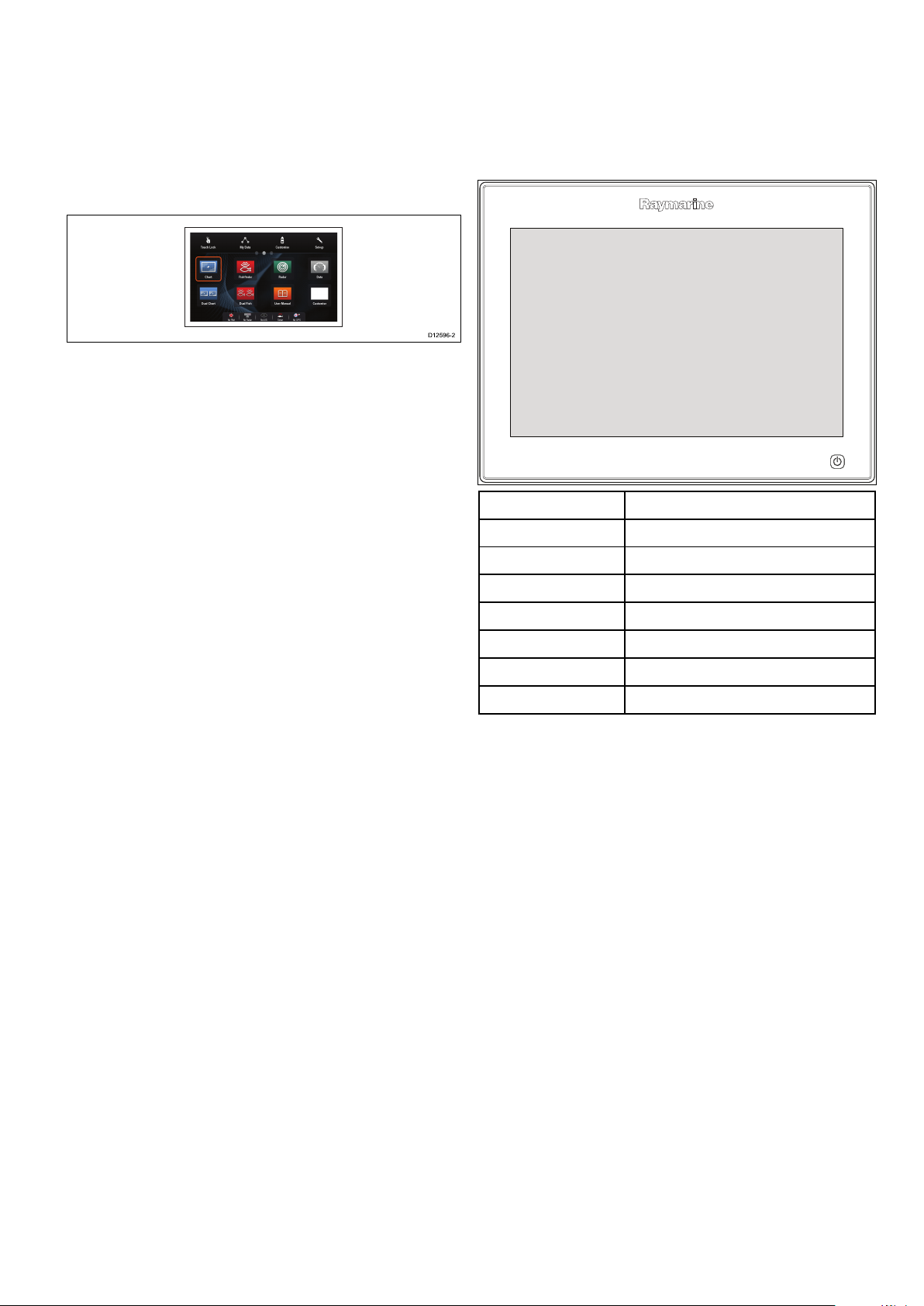
2.3Documentillustrations
D12596-2
2.4Productoverview
Productsmaydifferslightlyfromthoseshowninthe
illustrationsinthisdocument,dependingonproduct
variantanddateofmanufacture.
Theillustrationshownbelowisusedthroughout
thisdocumenttorepresentLightHouse
TM
powered
MFDsandunlessotherwisestatedappliestoall
multifunctiondisplayvariants.
Productinformation
gSSeriesMultifunctionDisplays(MFDs)are
touchscreendisplayswhichhaveHybridTouch
functionalitywhenpairedwitharemotekeypad.The
followingRaymarineMFDvariantsareavailable.
ModelPartnumber
gS95
gS95inverted
gS125
gS125inverted
gS165
gS165inverted
gS195
E70124
E70183
E70125
E70184
E70126
E70185
E70213
RefertotheOptimumviewabilitysectionfordetails
onstandardvsinverteddisplays.
HybridTouchoverview
IfyourmultifunctiondisplayfeaturesHybridT ouch,
thisenablesyoutooperatetheunitusingthe
touchscreenandthephysicalbuttons.
AHybridT ouchdisplayhasphysicalbuttons
whichcanbeusedinadditiontothetouchscreen.
Touchscreenonlymultifunctiondisplays(which
donothavephysicalbuttons)canbeconnected
toaremotekeypadwhichallowsHybridT ouch
functionality.
Documentandproductinformation
Allfunctionscanbeaccessedusingthetouchscreen.
However,theremaybesituations(suchasrough
seaconditions)whenitisnotappropriatetouse
thetouchscreen.Inthesesituations,Raymarine
stronglyrecommendsthatyouactivatethetouch
lockandusethephysicalbuttonstooperateyour
multifunctiondisplay.
15
Page 16

2.5LightHouseMFDOperation instructions
ForoperationinstructionsforyourMFD,
including‘GettingStarted’and‘SystemChecks’
informationpleaseusetheUserManualiconon
theHomescreen.
theLightHouseOperation
Instructions(81360)can
alsobedownloadedfrom
theRaymarinewebsite:
www.raymarine.com/manuals
16
gSSeriesinstallationinstructions
Page 17

Chapter3:Planningtheinstallation
Chaptercontents
•3.1Systemintegrationonpage18
•3.2Installationchecklistonpage24
•3.3Multipledatasources(MDS)overviewonpage24
•3.4Identifyingyourdisplayvariantonpage25
•3.5Networkingconstraintsonpage25
•3.6Systemprotocolsonpage26
•3.7Datamasteronpage27
•3.8Partssuppliedonpage28
•3.9Toolsrequiredforinstallationonpage29
•3.10Selectingalocationonpage29
Planningtheinstallation
17
Page 18
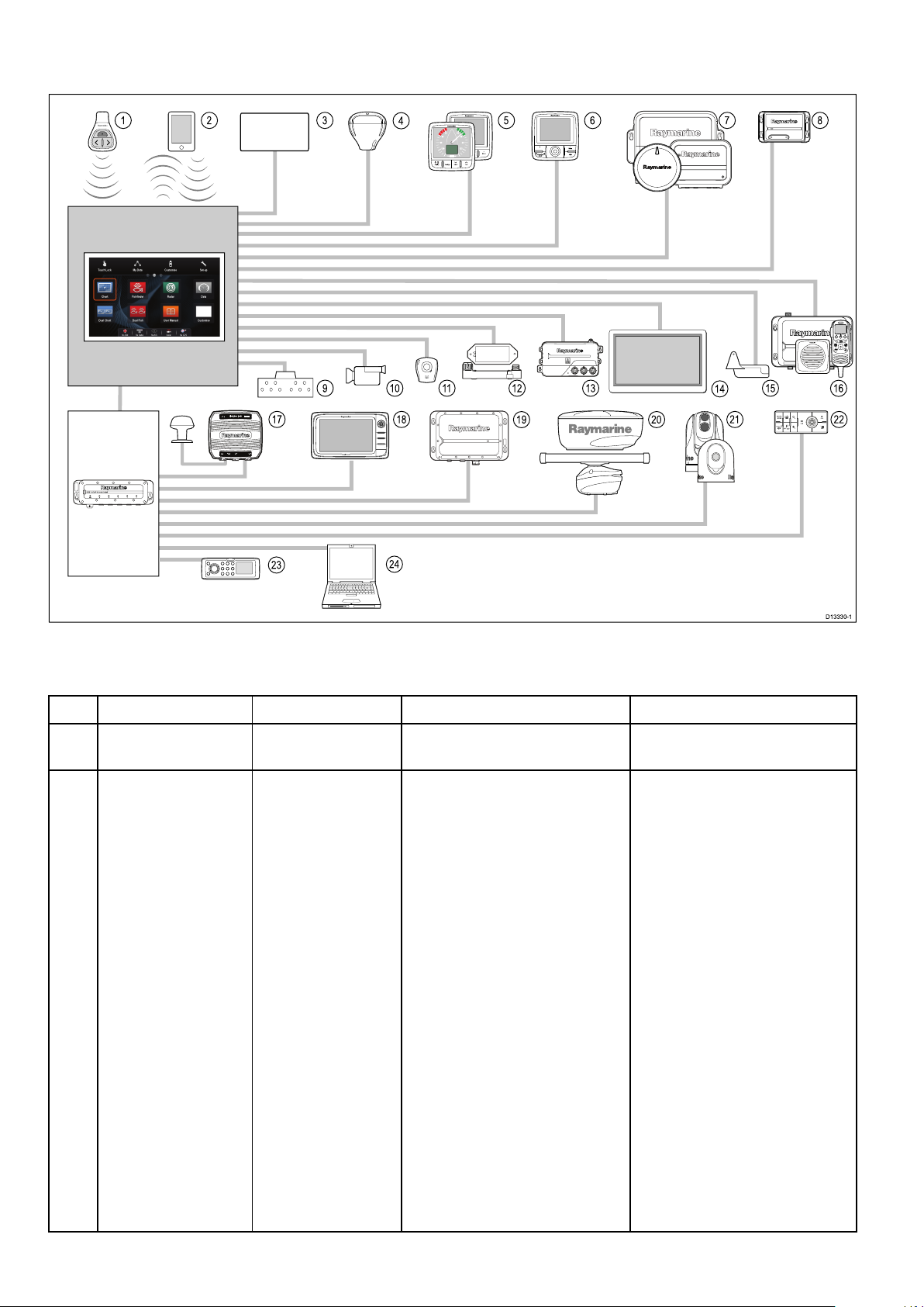
3.1Systemintegration
1 2 8
5 6
73
16
109 11 12 13 15
4
1817
19
20
21 22
23
24
D13330-1
14
0
0
0
0
0
AUDIO
0
0
ANTENNA
NETWORK
0
POWER
0
0
00
TackTrue/AppDisplay VMG
00
INTCM
Raymarine
®
multifunctiondisplays(MFDs)arecompatiblewithawiderangeofmarineelectronicsdevices.
MFDsusevariousprotocolstotransferdatabetweendevicesinyoursystem.Thetablebelowdetailswhich
devicesmaybeconnectedtoyourMFD,andthetypeofconnections(intermsofprotocolsandphysical
interfaces):
ItemDeviceTypeMaximumquantitySuitableDevicesConnections
1Remotecontrol1perMFDRaymarine
®
Bluetooth
RCU-3
2Mobiledevice
(Smartphone/T ablet)
1permultifunction
display.
ForRaymarine
streamingandremotecontrol
apps:
•AppleiPhone4(orlater)oriPad
2(orlater)
•Androiddevicewithminimum
1GHzprocessorandrunning
android2.2.2(orlater)
®
wirelessvideo
•Chartplottersyncwith
NavionicsMarineapp:Wi-Fi
•Videostreamingandremote
control:Wi-Fi
•Mediaplayercontrol:Bluetooth
2.1+EDRpowerclass1.5
(supportedprole:AVRCP1.0)
orlater
•AmazonKindleFire
Forchartplottersyncwith
NavionicsMarineapp:
•AppleiPhoneoriPad
•Android-compatiblesmartphone
ortablet
Formediaplayercontrol
(TouchscreenMFDsonly):
•AnyBluetooth-enableddevice
thatsupportsBluetooth2.1+
EDRpowerclass1.5(supported
prole:AVRCP1.0)
18
gSSeriesinstallationinstructions
Page 19

ItemDeviceTypeMaximumquantitySuitableDevicesConnections
3Vesseltanksensors
—third-party
4
GNSSReceiver
(external)—
Raymarine
5
Instruments—
Raymarine
•Upto5xfuel.
•1xfreshwater.
Third-partyNMEA2000interfacesNMEA2000(viaoptional
DeviceNetadaptorcables)
•1xwastewater.
•1xsewage.
•1xbait/sh.
1
®
Anycombinationofthefollowing:
•RS130GPS
SeaTalk,SeaTalk
0183
ng®
,orNMEA
•Raystar125GPS
•Raystar125+GPS(viaoptional
SeaTalktoSeaTalk
ng®
converter)
®
SeaTalk
ng®
bus
bandwidthandpower
loading.
Asdeterminedby
SeaTalk
•i50Depth,Speed,orTridata
•i60Wind,CHWind
ng®
:
SeaTalk,SeaTalk
ng®
•i70
•ST70+
•ST70
6Pilotcontrolheads—
Raymarine
®
Asdetermined
bySeaTalkor
SeaTalk
ng®
bandwidthand
powerloading,as
appropriate.
SeaTalk(viaoptionalSeaTalkto
SeaTalk
ng®
converter):
•i40Wind,Speed,Depth,or
Bidata
•ST60+Wind,Speed,Depth,
Rudder,orCompass
•ST40Wind,Speed,Depth,
Rudder,orCompass
SeaTalk
bus
•p70
ng®
:
SeaTalk,SeaTalk
ng®
•p70R
•ST70(SeaTalk
ng®
course
computeronly.)
•ST70+(SeaTalk
ng®
course
computeronly.)
SeaTalk(viaoptionalSeaTalkto
SeaTalk
ng®
converter):
•ST6002
•ST7002
Planningtheinstallation
•ST8002
7
Autopilots—
Raymarine
®
1
SeaTalk
•Evolutionautopilots
ng®
:
SeaTalk,SeaTalk
0183
ng®
,orNMEA
•AllSPXcoursecomputers
SeaTalk(viaoptionalSeaTalkto
SeaTalk
ng®
converter):
•ST1000
•ST2000
•S1000
•S1
19
Page 20

ItemDeviceTypeMaximumquantitySuitableDevicesConnections
•S2
•S3
8
AIS—Raymarine
®
1
•AIS350
•AIS650
•AIS950
SeaTalk
ng®
,orNMEA0183
8
AIS—third-party
9Vesseltrimtabs—
third-party
10
Analogvideo/cameraa6x/a7x=0
10IPcameraMultiple
11
Lifetag(Man
overboardalert)
12
Engineinterface—
Raymarine
®
1Third-partyNMEA
0183–compatibleAISClass
AorClassBreceiver/transceiver
1pair
Third-partyNMEA2000interfacesNMEA2000(viaoptional
CompositePALorNTSCvideo
a9x/a12x/e7/e7D
source
=1
cSeries=1
e9x/e12x/e165=2
eSSeries=1
gSSeries=2
•CAM200IP
Note:Whilstthird-party
ONVIFcompatibleIPcameras
maywork,Raymarine
guaranteetheircompatibility.
1basestation
AllRaymarine
basestations
1unitforeachengine
•ECI-100SeaTalk
CANbus
NMEA0183
DeviceNetadaptorcables)
BNCconnectors
ViaSeaTalk
®
cannot
®
Lifetag
SeaTalk(viaoptionalSeaTalkto
SeaTalk
hs
network
ng®
converter)
ng®
12
Engineinterface—
third-party
13Transducers
andsensors—
Raymarine
13Transducersand
sensors—Airmar
14Externaldisplay
1
Third-partyNMEA2000interfacesNMEA2000(viaoptional
DeviceNetadaptorcables)
1Analogtransducers:
®
•Wind
SeaTalk
converter)
ng®
(viaoptionaliTC-5
•Speed
•Depth
•Rudderreference
•Fluxgatecompass
1
•DT800SmartSensor
•DST800SmartSensor
SeaTalk
converter)
ng®
(viaoptionaliTC-5
•PB200weatherstation
a6x/a7x=0
a9x/a12x=1
cSeries=0
e7/e7D=0
e9x/e12x/e165=1
eS7x=0
e.g.HDTV
a9x/a12x=15pinD-Type
connector(VGAStyle)
e9x/e12x/e165=15pinD-Type
connector(VGAStyle)
eS9x/eS12x=HDMI
gSSeries=HDMI
eS9x/eS12x=1
gSSeries=1
20
gSSeriesinstallationinstructions
Page 21

ItemDeviceTypeMaximumquantitySuitableDevicesConnections
15
Sonartransducer
15DownVision
transducers
1•P48
•P58
Directconnectionto600W
internalsonarvariantdisplays.
•P74
•B6020º
•B6012º
•B744V
;OR:
•Any600watt/1Kwcompatible
transducer(viaoptionalE66066
adaptorcable)
;OR:
•AnyMinnKotatransducer(via
optionalA62363adaptorcable)
Connectionviaexternal
Raymarine
®
SonarModule:
•Anysonarmodule-compatible
transducer
™
1Directconnectiontointernal
CHIRPDownVision
TM
variant
DownVision
™
variantdisplays.
DirectconnectiontoCHIRP
displays
•CPT-100—Transommount
•CPT-110—Thru-hullplastic
•CPT-120—Thru-hullbronze
16
DSCVHFradio—
Raymarine
®
1
SeaTalk
•Ray50
ng®
:
NMEA0183orSeaTalk
ng®
•Ray60
•Ray70
•Ray260
•Ray260AIS
NMEA0183:
•Ray50
•Ray60
•Ray70
•Ray49
•Ray55
•Ray218
Planningtheinstallation
•Ray240
17
Raymarine
®
Sirius
marineweather/
satelliteradioreceiver
(NorthAmericaonly)
1
SeaTalk
•SR150
•SR100
hs
:
SeaTalk
hs
,SeaTalk
ng®
•SR6
SeaTalk
ng®
:
•SR50
21
Page 22

ItemDeviceTypeMaximumquantitySuitableDevicesConnections
18Additional
multifunction
display(s)—
Raymarine
®
93rdgenerationRaymarine
multifunctiondisplays
SeaTalk
•aSeries
hs
(recommended):
•cSeries
•eSeries
•gSSeries
•eSSeries
®
SeaTalk
hs
Note:Y oucanconnect
Raymarine
®
multifunction
displaysusingNMEA0183or
SeaTalk
ng®
butnotallfunctions
aresupported.
Note:Visit
www.raymarine.comto
downloadthelatestsoftware
versionforyourdisplay.
18Additional
multifunction
display(s)—
third-party
•Connectionsto
multifunction
displayNMEA
outputs:4
NMEA0183–compatible
chartplottersandmultifunction
displays
NMEA0183
•Connectionsto
multifunction
displayNMEA
inputs:2
19
SonarModules
(Fishnder)—
Raymarine
®
Multiple
•CP100—DownVision
•CP200—SideVision
™
™
SeaTalk
hs
•CP300/CP370—Traditional
sonar
•CP450C/CP470—CHIRP
sonar
•CP570CHIRPprofessional
sonar
•600WSonarandCHIRP
DownVision
20Radar—Raymarine
®
2AllRaymarine
RadomesandHDorSuperHD
radarscanners.
Note:Pleaseensureyour
radarscannerisusingthelatest
softwareversion.
21Thermalcamera—
Raymarine
®
1
•T200Series
•T300Series
•T400Series
•T800Series
•T900Series
22RemotekeypadMultiple•RMK-9
™
variantdisplays.
®
Non-HDDigital
SeaTalk
SeaTalk
hs
hs
(forcontrol),BNC
connector(forvideo)
SeaTalk
hs
22
gSSeriesinstallationinstructions
Page 23

ItemDeviceTypeMaximumquantitySuitableDevicesConnections
23Fusionentertainment
systems
MultipleFusion700seriesentertainment
systems:
•MS-IP700
•MS-AV700
24
PC/laptop
1
Windows-compatiblePCorlaptop
runningRaymarine
®
Plannersoftware.
SeaTalk
SeaTalk
hs
hs
Voyage
Note:Raymarine
®
cannotguaranteethecompatibilityofanythird-partydeviceslistedabove.
Planningtheinstallation
23
Page 24

3.2Installationchecklist
Installationincludesthefollowingactivities:
InstallationTask
1Planyoursystem.
2
Obtainallrequiredequipmentandtools.
3
Siteallequipment.
4Routeallcables.
5
Drillcableandmountingholes.
6Makeallconnectionsintoequipment.
7
Secureallequipmentinplace.
8Poweronandtestthesystem.
3.3Multipledatasources(MDS) overview
Installationsthatincludemultipleinstancesofdata
sourcescancausedataconicts.Anexampleisan
installationfeaturingmorethanonesourceofGPS
data.
MDSenablesyoutomanageconictsinvolvingthe
followingtypesofdata:
•GPSPosition.
•Heading.
•Depth.
•Speed.
•Wind.
Typicallythisexerciseiscompletedaspartofthe
initialinstallation,orwhennewequipmentisadded.
IfthisexerciseisNOTcompletedthesystemwill
automaticallyattempttoresolvedataconicts.
However,thismayresultinthesystemchoosinga
sourceofdatathatyoudonotwanttouse.
IfMDSisavailablethesystemcanlisttheavailable
datasourcesandallowyoutoselectyourpreferred
datasource.ForMDStobeavailableallproducts
inthesystemthatusethedatasourceslisted
abovemustbeMDS-compliant.Thesystemcan
listanyproductsthatareNOTcompliant.Itmay
benecessarytoupgradethesoftwareforthese
non-compliantproductstomakethemcompliant.
VisittheRaymarinewebsite(www.raymarine.com)
toobtainthelatestsoftwareforyourproducts.If
MDS-compliantsoftwareisnotavailableandyoudo
NOTwantthesystemtoautomaticallyattemptto
resolvedataconicts,anynon-compliantproduct(s)
canberemovedorreplacedtoensuretheentire
systemisMDS-compliant.
24
gSSeriesinstallationinstructions
Page 25
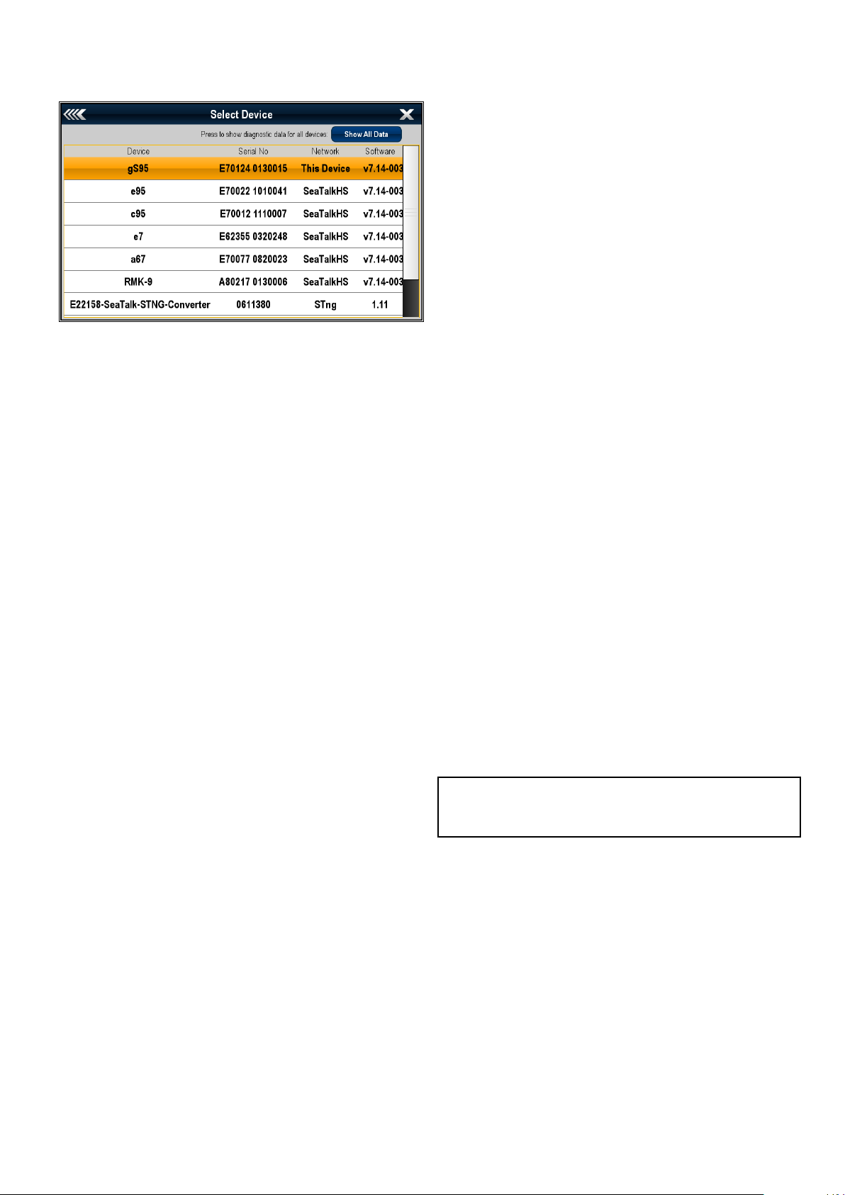
3.4Identifyingyourdisplayvariant
3.5Networkingconstraints
Todiscoverwhichmodeldisplayyouhavefollowthe
stepsbelow:
Fromthehomescreen:
1.SelectSet-up.
2.SelectMaintenance.
3.SelectDiagnostics.
4.SelectSelectDevice.
5.SearchtheNetworkcolumnforthe'ThisDevice'
entry.
6.TheDevicecolumnforthisrecordwilllistthe
modelofyourdisplay.
Upto10LightHousepoweredMFDscan
beconnectedtogetherusingSeaTalk
hs
.Itis
recommendedthatallnetworkeddisplayscontain
thesamesoftwareversion.
Softwareversions
•AllnetworkedaaSeries,cSeriesandeSeries
displaysmustcontainLightHousesoftware
releaseV4.32orlater.
•AllnetworkedgSSeriesdisplaysmustcontain
LightHousesoftwarereleaseV7.43orlater.
•AllnetworkedeSSeriesdisplaysmustcontain
LightHousesoftwarereleaseV14.xxorlater.
Master/repeateroperation
•Anynetworkfeaturingmorethan1MFDmusthave
1ofthedisplaysdesignatedastheDataMaster.
•TheDataMasterdisplaywillreceivedatathrough
NMEA0183and/orSeaT alk
dataoverSeaTalk
hs
toothernetworkeddisplays.
ng®
,andbridgethe
Homescreensharing
•Whennetworked,MFDscansharetheData
Master’sHomescreen.
Cartographysharing
•Thecartographycontainedonchartcardsis
alwaysusedinpreferencetoembeddedworld
basemaps.
•Chartcardcartographycanbesharedbetween
networkedMFDs.
Radaroperation
•MFDssupporttheuseofupto2Radarscanners
simultaneously.
•ThedatasuppliedbyaconnectedRadar
scanner(s)isrepeatedtonetworkeddisplays.
Note:AllMFDsmusthaveLightHouseIIRelease
V12.26softwareorlatertoenablemultipleradar
support.
Sonar/DownVision
™
/SideVision
™
operation
•Youcanconnectanexternalsonarmodulestothe
MFDviatheSeaT alk
•600WsonarandCHIRPDownVision
hs
network.
™
variant
displaysincludeaninternalsonarmodulewhich
enablesdirectconnectionofacompatible
transducer.
Planningtheinstallation
•Youcanhavemultipleactivesonarmodules
(internalandexternal)onanetwork.
•Thedatasuppliedbythesonarmoduleisrepeated
tonetworkeddisplays.
25
Page 26
Note:
PAGE
ACTIVE
WPTS
MOB
MENU
DATA
CANCELOK
RANGE
IN
OUT
PAGE
ACTIVE
WPTS
MOB
MENU
DATA
CANCELOK
RANGE
IN
OUT
3.6Systemprotocols
•AllMFDsmusthaveLightHouseIIRelease
V10.41softwareorlatertoenablemultiplesonar
support.
•Sonarmodulesshouldbeupdatedtothe
latestavailablesoftwareversiontoensure
compatibility.
Incompatibledisplays
Ifyouconnectamultifunctiondisplaytoyoursystem
thatisnotcompatible,awarningmessagewillbe
displayeduntilyoudisconnecttheincompatible
devicefromyournetwork.
YourMFDisnotcompatiblewiththefollowing
Raymarinedisplays:
Multifunction
ProductImage
displayGeneration
G-Series
E-Series
2ndgeneration
2ndgeneration
Widescreen
YourMultifunctionDisplaycanconnecttovarious
instrumentsanddisplaystoshareinformationand
soimprovethefunctionalityofthesystem.These
connectionsmaybemadeusinganumberof
differentprotocols.Fastandaccuratedatacollection
andtransferisachievedbyusingacombinationof
thefollowingdataprotocols:
•SeaTalk
•SeaTalk
hs
ng
•NMEA2000
•SeaTalk
•NMEA0183
Note:Youmayndthatyoursystemdoesnot
usealloftheconnectiontypesorinstrumentation
describedinthissection.
SeaTalk
SeaTalk
hs
hs
isanethernetbasedmarinenetwork.This
highspeedprotocolallowscompatibleequipment
tocommunicaterapidlyandsharelargeamountsof
data.
InformationsharedusingtheSeaT alk
hs
network
includes:
C-Series
Widescreen
E-SeriesClassic
C-SeriesClassic
2ndgeneration
•Sharedcartography(betweencompatible
displays).
•Digitalradardata.
•Sonardata.
1stgeneration
Seatalk
SeaTalk
ng
ng
(NextGeneration)isanenhancedprotocol
forconnectionofcompatiblemarineinstruments
andequipment.ItreplacestheolderSeaTalkand
1stgeneration
SeaTalk
SeaTalk
2
protocols.
ng
utilizesasinglebackbonetowhich
compatibleinstrumentsconnectusingaspur.Data
andpowerarecarriedwithinthebackbone.Devices
thathavealowdrawcanbepoweredfromthe
network,althoughhighcurrentequipmentwillneed
tohaveaseparatepowerconnection.
SeaTalk
ng
isaproprietaryextensiontoNMEA2000
andtheprovenCANbustechnology.Compatible
NMEA2000andSeaT alk/SeaTalk
2
devicescan
alsobeconnectedusingtheappropriateinterfaces
oradaptorcablesasrequired.
NMEA2000
NMEA2000offerssignicantimprovementsover
NMEA0183,mostnotablyinspeedandconnectivity.
Upto50unitscansimultaneouslytransmitand
receiveonasinglephysicalbusatanyonetime,
witheachnodebeingphysicallyaddressable.The
standardwasspecicallyintendedtoallowfor
26
gSSeriesinstallationinstructions
Page 27

awholenetworkofmarineelectronicsfromany
manufacturertocommunicateonacommonbusvia
standardizedmessagetypesandformats.
SeaTalk
SeaTalkisaprotocolwhichenablescompatible
instrumentstoconnecttoeachotherandsharedata.
TheSeaT alkcablesystemisusedtoconnect
compatibleinstrumentsandequipment.Thecable
carriespoweranddataandenablesconnection
withouttheneedforacentralprocessor.
Additionalinstrumentsandfunctionscanbeaddedto
aSeaTalksystem,simplybypluggingthemintothe
network.SeaT alkequipmentcanalsocommunicate
withothernon-SeaT alkequipmentviatheNMEA
0183standard,providedasuitableinterfaceisused.
3.7Datamaster
Anysystemcontainingmorethanonenetworked
multifunctiondisplaymusthaveadesignateddata
master.
Thedatamasteristhedisplaywhichservesasa
primarysourceofdataforalldisplays,italsohandles
allexternalsourcesofinformation.Forexample
thedisplaysmayrequireheadinginformationfrom
theautopilotandGPSsystems,usuallyreceived
throughaSeaTalk
masteristhedisplaytowhichtheSeaTalk,NMEA
andanyotherdataconnectionsaremade,itthen
bridgesthedatatotheSeaT alk
compatiblerepeatdisplays.Informationsharedby
thedatamasterincludes:
•Cartography
ng
orNMEAconnection.Thedata
hs
networkandany
NMEA0183
TheNMEA0183DataInterfaceStandardwas
developedbytheNationalMarineElectronics
AssociationofAmerica.Itisaninternational
standardtoenableequipmentfrommanydifferent
manufacturerstobeconnectedtogetherandshare
information.
TheNMEA0183standardcarriessimilarinformation
toSeaTalk.Howeverithastheimportantdifference
thatonecablewillonlycarryinformationinone
direction.ForthisreasonNMEA0183isgenerally
usedtoconnectadatareceiverandatransmitter
together,e.g.acompasssensortransmitting
headingtoaradardisplay.Thisinformationis
passedin‘sentences’,eachofwhichhasathree
lettersentenceidentier.Itisthereforeimportant
whencheckingcompatibilitybetweenitemsthatthe
samesentenceidentiersareusedsomeexamples
ofwhichare:
•VTG-carriesCourseandSpeedOverGround
data.
•GLL-carrieslatitudeandlongitude.
•Routesandwaypoints
•Radar
•Sonar
•Datareceivedfromtheautopilot,instruments,the
engineandotherexternalsources.
Yoursystemmaybewiredforredundancywithdata
connectionsmadetorepeatdisplays.Howeverthese
connectionswillonlybecomeactiveintheeventofa
faultand/orreassignmentofthedatamaster.
Inanautopilotsystemwhichdoesnotcontaina
dedicatedpilotcontrolheadtheDatamasteralso
actsasthecontrolfortheautopilot.
•DBT-carrieswaterdepth.
•MWV-carriesrelativewindangleandwindspeed
data.
NMEABaudrates
TheNMEA0183standardoperatesatanumber
ofdifferentspeeds,dependingupontheparticular
requirementorequipmentcapabilities.Typical
examplesare:
•4800baudrate.Usedforgeneralpurpose
communications,includingFastHeadingdata.
•38400baudrate.UsedforAISandotherhigh
speedapplications.
Planningtheinstallation
27
Page 28
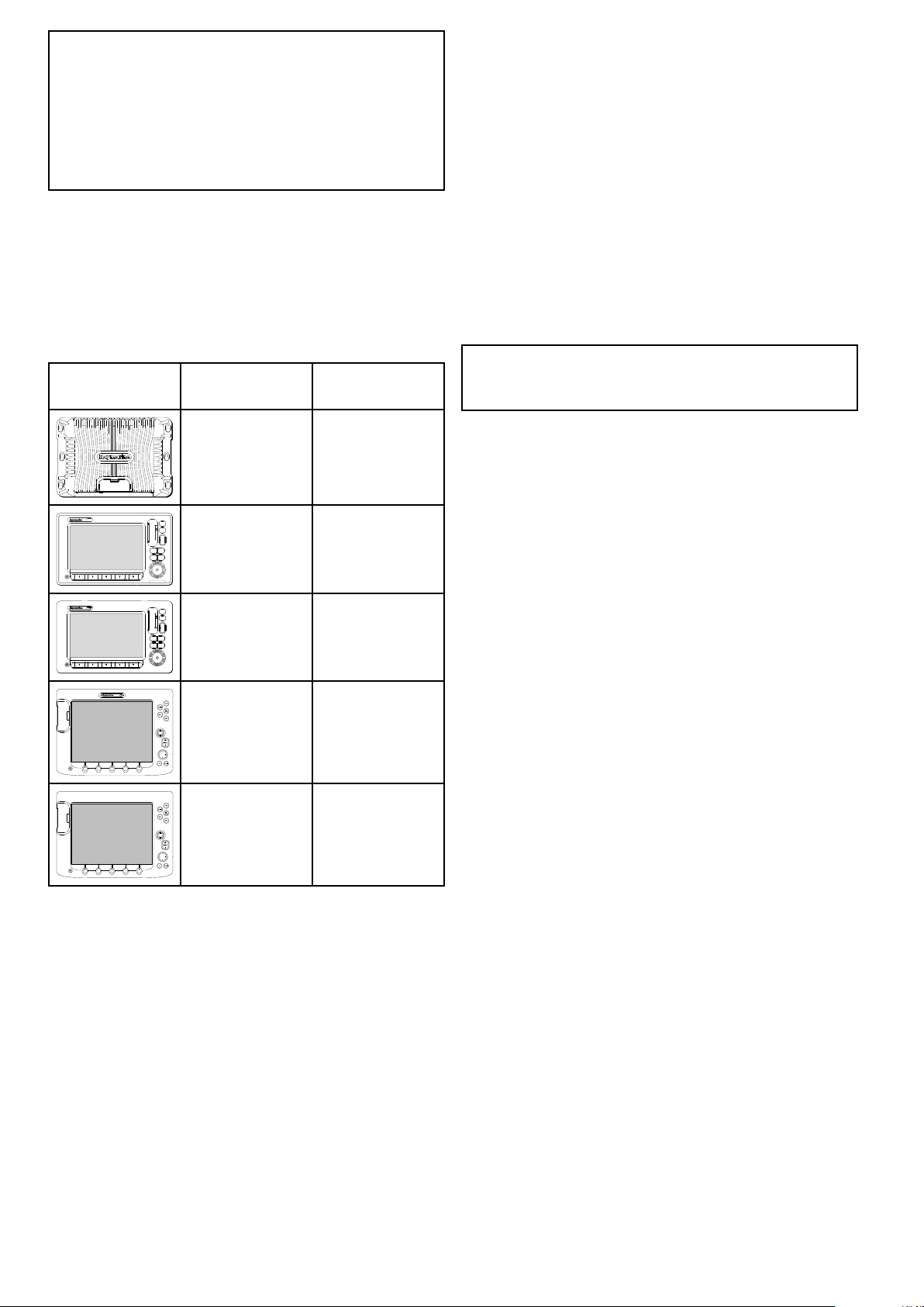
3.8Partssupplied
1 2
8
13
14
16
17
18
9 10
12
11
3
4 5
6
7
15
x4
x2
x4 x4
D12886-2
D13051-2
1 2 3
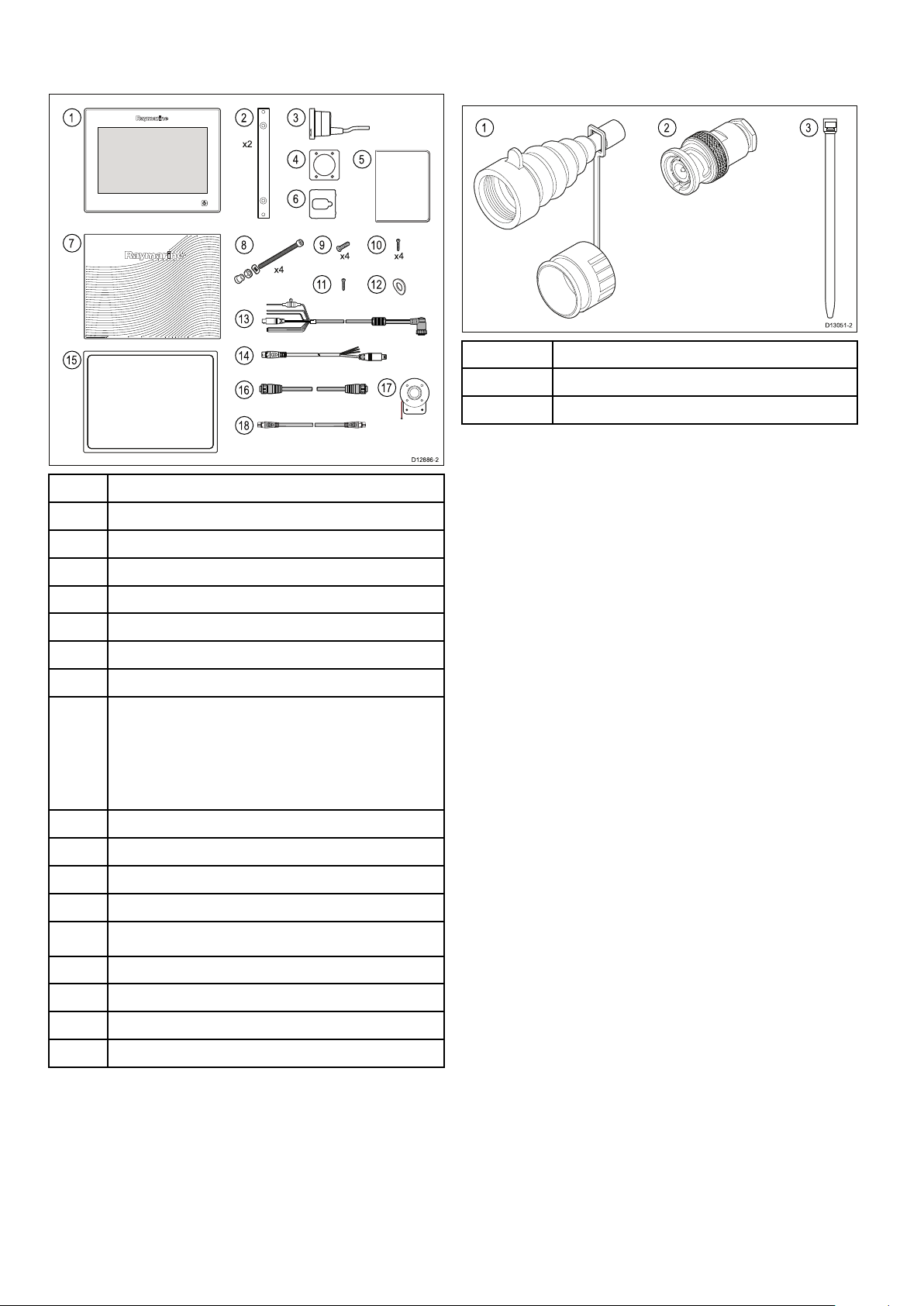
HD-SDIadditionalpartssupplied
Thefollowingpartsaresuppliedwithyourproduct.
1
Multifunctiondisplay
22xDisplaymountingbrackets
ThegS195issuppliedwiththefollowingadditional
partsforusewiththeHD-SDIconnection.
1Protectiveboot
2
4
75ohmBNCconnector
Cabletiesx2(tosecuretheprotectiveboot)
3
4
5
6
7
8
9
RCR-2RemoteCardReader
MountinggasketforRCR-2
Documentpack
RCR-2inlaycardx2
Suncover
4xMountingbolts,washers,locknutsandfeet
4xBracketxings
•gS95=M5x25panhead
•gS125andgS165=M5x25countersunk
•gS195=M5x60countersunk
10
11
12
13
14
4xRCR-2xings(self-tappingscrews)
M5x10panheadscrew(notsuppliedwithgS95)
M5Wavywasher(foradditionalgroundingstrap)
1.5m(4.9ft)Power/Datacable
2m(6.6ft)Video/Alarmcable
15Displaymountinggasket
16
2m(6.6ft)RayNetcable
17Auxiliaryalarm
18
28
1m(3.28ft)SeaT alk
ng
spurcable
gSSeriesinstallationinstructions
Page 29
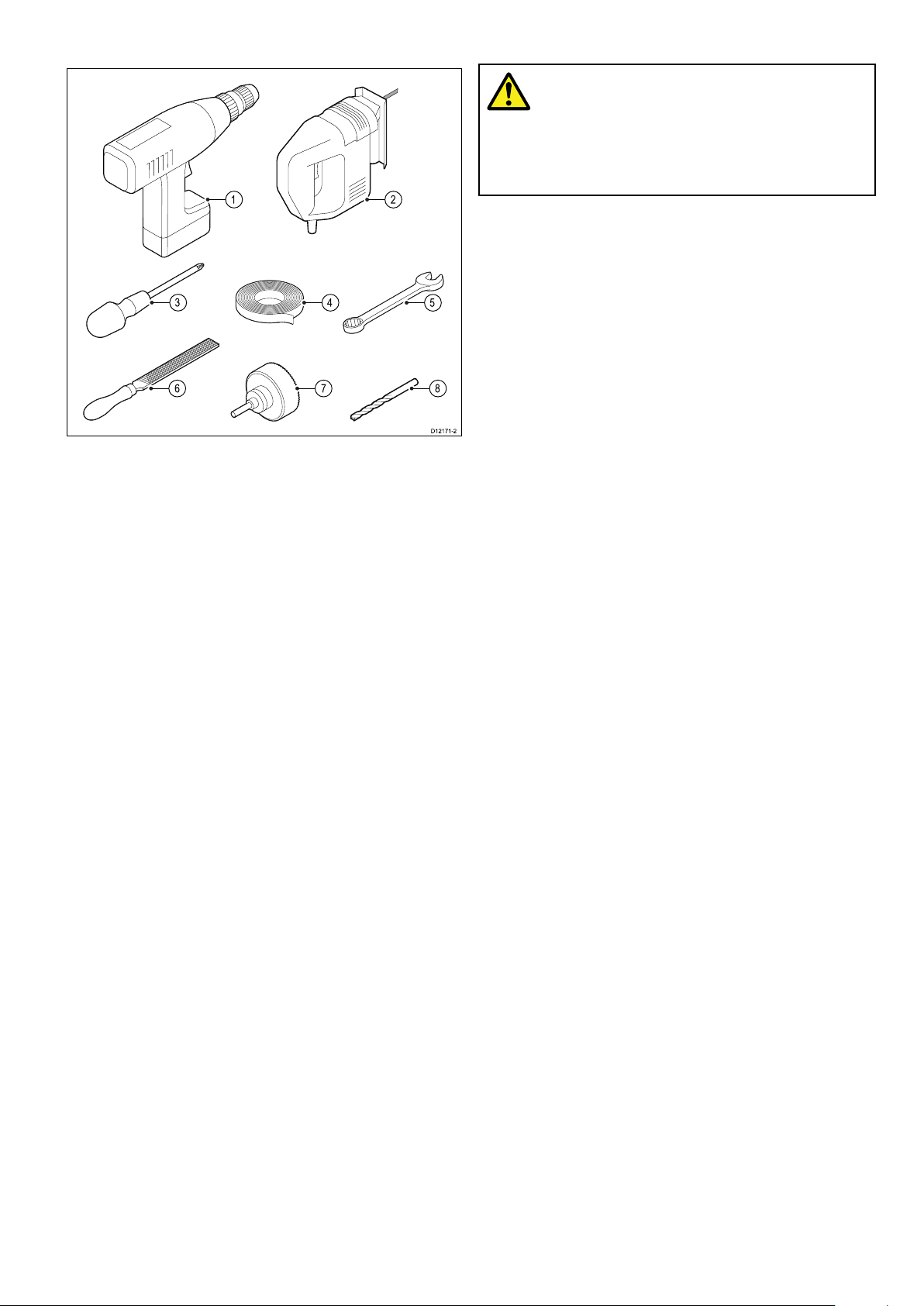
3.9Toolsrequiredforinstallation
D12171-2
1
4
5
3
876
2
3.10Selectingalocation
Warning:Potentialignitionsource
ThisproductisNOTapprovedforusein
hazardous/ammableatmospheres.Do
NOTinstallinahazardous/ammable
atmosphere(suchasinanengineroom
ornearfueltanks).
Generallocationrequirements
Whenselectingalocationforyourproductitis
importanttoconsideranumberoffactors.
Keyfactorswhichcanaffectproductperformance
are:
•Ventilation
Toensureadequateairow:
–Ensurethatproductismountedina
compartmentofsuitablesize.
1.Powerdrill.
2.Jigsaw.
3.Pozidrivescrewdriver.
4.Adhesivetape.
5.Spannerforsurfacemountingorbracket
mountingxings.
6.File.
7.Holesawforushmounting(Forholesawsize
refertoyourproduct’smountingtemplate).
8.Drillbitforsurfacemountingorushmounting.
AdditionaltoolsforFlushmounting
Forbestresultswhenushmountingthedisplays
itisrecommendedthatarouterisusedtocutout
therebate.
–Ensurethatventilationholesarenotobstructed.
Allowadequateseparationofallequipment.
Anyspecicrequirementsforeachsystem
componentareprovidedlaterinthischapter.
•Mountingsurface
Ensureproductisadequatelysupportedona
securesurface.Donotmountunitsorcutholes
inplaceswhichmaydamagethestructureofthe
vessel.
•Cabling
Ensuretheproductismountedinalocationwhich
allowsproperrouting,supportandconnectionof
cables:
–Minimumbendradiusof100mm(3.94in)
unlessotherwisestated.
–Usecableclipstopreventstressonconnectors.
–Ifyourinstallationrequiresmultipleferritesto
beaddedtoacablethenadditionalcableclips
shouldbeusedtoensuretheextraweightof
thecableissupported.
•Wateringress
Theproductissuitableformountingbothabove
andbelowdecks.Althoughtheunitiswaterproof,
itisgoodpracticetolocateitinaprotectedarea
awayfromprolongedanddirectexposuretorain
andsaltspray.
Planningtheinstallation
•Electricalinterference
Selectalocationthatisfarenoughawayfrom
devicesthatmaycauseinterference,suchas
motors,generatorsandradiotransmitters/
receivers.
•Powersupply
Selectalocationthatisascloseaspossibletothe
vessel’sDCpowersource.Thiswillhelptokeep
cablerunstoaminimum.
29
Page 30
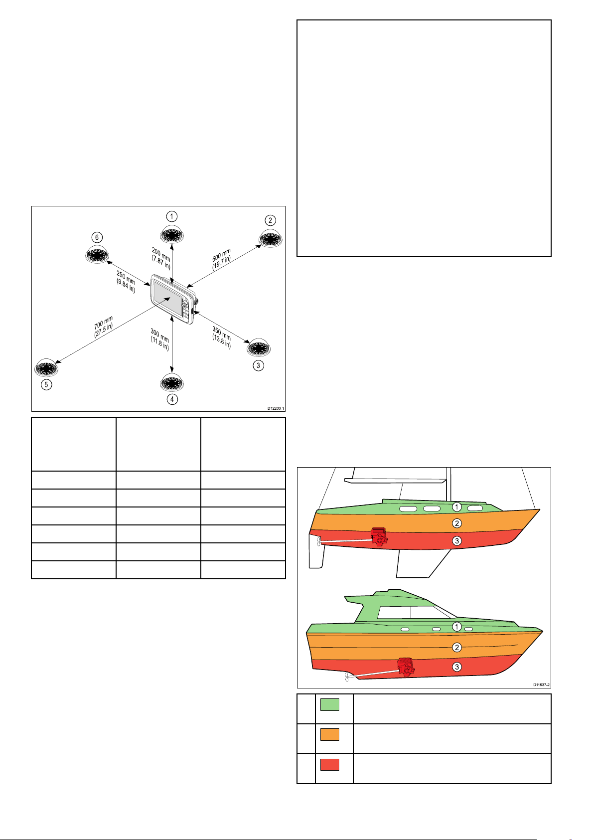
Compasssafedistance
D1220 3-1
200 mm
(7.87 in)
350 mm
(13.8 in)
300 mm
(11.8 in
)
700 mm
(27.5 in)
500 mm
(19.7 in)
250 mm
(9.84 in)
1
2
3
4
5
6
D11537 -2
1
2
3
1
2
3
Topreventpotentialinterferencewiththevessel's
magneticcompasses,ensureanadequatedistance
ismaintainedfromthedisplay.
Whenchoosingasuitablelocationforthe
multifunctiondisplayyoushouldaimtomaintainthe
maximumpossibledistancebetweenthedisplayand
anycompasses.Typicallythisdistanceshouldbeat
least1m(3ft)inalldirections.Howeverforsome
smallervesselsitmaynotbepossibletolocate
thedisplaythisfarawayfromacompass.Inthis
situation,thefollowingguresprovidetheminimum
safedistancethatshouldbemaintainedbetweenthe
displayandanycompasses.
Caution:Mountingsurface
requirements
Thisproductisheavy.T opreventpotential
damagetotheproductand/oryour
vessel,observethefollowingBEFORE
installingtheproduct:
•Refertotheweightinformationprovided
inthetechnicalspecicationforthis
productandensurethattheintended
mountingsurfaceissuitableforbearing
theweight.
•Ifthemountingsurfaceisnotsuitable
fortheproductweight,youmayneedto
reinforcethemountingsurface.
•Ifindoubt,refertoaprofessional
marineequipmentinstallerforfurther
guidance.
GPSlocationrequirements
Inadditiontogeneralguidelinesconcerningthe
locationofmarineelectronics,thereareanumber
ofenvironmentalfactorstoconsiderwheninstalling
equipmentwithaninternalGPSantenna.
Compass
positionin
relationto
Item
display
1Top
2Rear
3Right-handside
4Underside
5
6
Front
Left-handside250mm(9.84in.)
Mountinglocation
•AboveDecksmounting:
ProvidesoptimalGPSperformance.(For
equipmentwithappropriatewaterproofrating.)
•BelowDecksmounting:
Minimumsafe
distancefrom
display
GPSperformancemaybelesseffectiveandmay
requireanexternalGPSantennamountedabove
decks.
200mm(7.87in.)
500mm(19.7in.)
350mm(13.8in.)
300mm(11.8in.)
700mm(27.5in.)
1.
ThislocationprovidesoptimalGPS
performance(abovedecks).
2.
Inthislocation,GPSperformancemaybeless
effective.
30
3.
ThislocationisNOTrecommendedforGPS
antenna.
gSSeriesinstallationinstructions
Page 31

Vesselconstruction
3
4
2
1
D13119-1
1 2
D13120-1
Theconstructionofyourvesselcanhaveanimpact
onGPSperformance.Forexample,theproximity
ofheavystructuresuchasastructuralbulkhead,
ortheinterioroflargervesselsmayresultina
reducedGPSsignal.Beforelocatingequipment
withaninternalGPSantennabelowdecks,seek
professionalassistanceandconsideruseofan
externalGPSantennamountedabovedecks.
Viewingangleconsiderations
Asdisplaycontrast,colorandnightmode
performanceareallaffectedbytheviewingangle,
Raymarinerecommendsyoutemporarilypowerup
thedisplaywhenplanningtheinstallation,toenable
youtobestjudgewhichlocationgivestheoptimum
viewingangle.
LCDorientation
Prevailingconditions
Theweatherandlocationofthevesselcanaffectthe
GPSperformance.Typicallycalmclearconditions
provideforamoreaccurateGPSx.Vesselsat
extremenortherlyorsoutherlylatitudesmayalso
receiveaweakerGPSsignal.GPSantennamounted
belowdeckswillbemoresusceptibletoperformance
issuesrelatedtotheprevailingconditions.
EMCinstallationguidelines
Raymarineequipmentandaccessoriesconformto
theappropriateElectromagneticCompatibility(EMC)
regulations,tominimizeelectromagneticinterference
betweenequipmentandminimizetheeffectsuch
interferencecouldhaveontheperformanceofyour
system
CorrectinstallationisrequiredtoensurethatEMC
performanceisnotcompromised.
Note:InareasofextremeEMCinterference,
someslightinterferencemaybenoticedonthe
product.Wherethisoccurstheproductandthe
sourceoftheinterferenceshouldbeseparatedby
agreaterdistance.
ForoptimumEMCperformancewerecommend
thatwhereverpossible:
•Raymarineequipmentandcablesconnectedto
itare:
–Atleast1m(3ft)fromanyequipment
transmittingorcablescarryingradiosignalse.g.
VHFradios,cablesandantennas.Inthecase
ofSSBradios,thedistanceshouldbeincreased
to7ft(2m).
–Morethan2m(7ft)fromthepathofaradar
beam.Aradarbeamcannormallybeassumed
tospread20degreesaboveandbelowthe
radiatingelement.
•Theproductissuppliedfromaseparatebattery
fromthatusedforenginestart.Thisisimportantto
preventerraticbehavioranddatalosswhichcan
occuriftheenginestartdoesnothaveaseparate
battery.
•Raymarinespeciedcablesareused.
•Cablesarenotcutorextended,unlessdoingsois
detailedintheinstallationmanual.
Note:Whereconstraintsontheinstallation
preventanyoftheaboverecommendations,
alwaysensurethemaximumpossibleseparation
betweendifferentitemsofelectricalequipment,to
providethebestconditionsforEMCperformance
throughouttheinstallation
Planningtheinstallation
Raymarinemultifunctiondisplays(MFDs)canbe
viewedfromwideanglestoptobottomandleftto
right.
1.Top
2.Bottom
3.Left
4.Right
LCDscanbeorientatedin2directions:
1.12O’clock—Standardorientation(Inthe12
O’clockorientationtheLCDisbetterviewedfrom
toptobottomthanitisfrombottomtotop.)
2.6O’clock—Invertedorientation(Inthe6
O’clockorientationtheLCDisbetterviewedfrom
bottomtotopthanitisfromtoptobottom.)
ThetablebelowdetailstheLCDorientationforeach
gSSeriesMFD.
LCD
MFD
gS95
(E70124)
gS125
(E70125)
orientationMFD
12O’clockgS95INV
(E70183)
12O’clockgS125INV
(E70184)
LCD
orientation
6O’clock
6O’clock
31
Page 32

LCD
A C
D E
B
D12716-2
A C D F
B
E
D12725-1
MFD
orientationMFD
LCD
orientation
gS165
(E70126)
Productdimensions
A246.8mm
B188.2mm
12O’clockgS165INV
(E70185)
gS195
(E70213)
gS95gS125gS165gS195
(9.7in)
(7.4in)
311.8mm
(12.3in)
237.1mm
(9.3in)
383.2mm
(15in)
284.7mm
(11.2in)
6O’clock
6O’clock
433.9mm
(17.1in)
391.2mm
(15.4in)
C
8mm
(0.31in)
D69mm
(2.72in)
E114.1mm
(7.8in)
Cardreaderdimensions
A
B
C8.5mm(0.33in)
55mm(2.17in)
55mm(2.17in)
8mm
(0.31in)
70mm
(2.75in)
114.1mm
(7.8in)
8mm
(0.31in)
69mm
(2.72in)
114.1mm
(7.8in)
8mm
(0.31in)
75.9mm
(3in)
114.1mm
(7.8in)
D
E
F
32
36mm(1.4in)
39.2mm(1.5in)
90mm(3.5in)
gSSeriesinstallationinstructions
Page 33

Chapter4:Cablesandconnections
Chaptercontents
•4.1Generalcablingguidanceonpage34
•4.2gS95/gS125/gS165Connectionsoverviewonpage35
•4.3gS195connectionsoverviewonpage35
•4.4Poweranddata(combined)connectiononpage36
•4.5PoweroverEthernet(PoE)onpage38
•4.6Cardreaderconnectiononpage38
•4.7Auxiliaryalarmconnectiononpage39
•4.8SeaTalk
•4.9NMEA2000connectiononpage40
•4.10SeaTalkconnectiononpage41
•4.11NMEA0183connection—Power/NMEA/Videocableonpage41
•4.12Gigabitnetworkingonpage42
•4.13Sonarmoduleconnectiononpage43
•4.14Radarnetworkconnectiononpage44
•4.15GNSS/GPSconnectiononpage46
•4.16AISconnectiononpage47
•4.17Fastheadingconnectiononpage47
•4.18Keypadnetworkconnectiononpage48
•4.19Weatherreceiverconnectiononpage48
•4.20Videoconnection—compositeonpage49
•4.21Camera(Video/Alarm)connectiononpage49
•4.22HDMIvideooutputonpage50
•4.23IPCameraconnectiononpage50
•4.24HD-SDIconnection(gS195)onpage51
•4.25Thermalcameraconnectiononpage52
•4.26Fusionnetworkconnectiononpage54
•4.27FusionNMEA2000connectiononpage54
•4.28Mediaplayerconnectiononpage55
•4.29Raymarinemobileappconnectiononpage55
•4.30Bluetoothremotecontrolconnectiononpage56
ng®
connectionsonpage39
Cablesandconnections33
Page 34

4.1Generalcablingguidance
100 mm (4 in)
200 mm (8 in)
Suppressionferrites
•Raymarinecablesmaybepre-ttedorsupplied
withsuppressionferrites.Theseareimportantfor
correctEMCperformance.Ifferritesaresupplied
separatelytothecables(i.e.notpre-tted),you
musttthesuppliedferrites,usingthesupplied
instructions.
•Ifaferritehastoberemovedforanypurpose(e.g.
installationormaintenance),itmustbereplacedin
theoriginalpositionbeforetheproductisused.
•Useonlyferritesofthecorrecttype,suppliedby
Raymarineoritsauthorizeddealers.
•Whereaninstallationrequiresmultipleferritesto
beaddedtoacable,additionalcableclipsshould
beusedtopreventstressontheconnectorsdue
totheextraweightofthecable.
Connectionstootherequipment
Requirementforferritesonnon-Raymarinecables
IfyourRaymarineequipmentistobeconnected
tootherequipmentusingacablenotsuppliedby
Raymarine,asuppressionferriteMUSTalwaysbe
attachedtothecableneartheRaymarineunit.
Cabletypesandlength
Itisimportanttousecablesoftheappropriatetype
andlength
•Unlessotherwisestateduseonlystandardcables
ofthecorrecttype,suppliedbyRaymarine.
•Ensurethatanynon-Raymarinecablesareofthe
correctqualityandgauge.Forexample,longer
powercablerunsmayrequirelargerwiregauges
tominimizevoltagedropalongtherun.
Alwaysroutedatacablesasfarawayaspossible
from:
•otherequipmentandcables,
•highcurrentcarryingacanddcpowerlines,
•antennae.
Strainrelief
Ensureadequatestrainreliefisprovided.Protect
connectorsfromstrainandensuretheywillnotpull
outunderextremeseaconditions.
Circuitisolation
Appropriatecircuitisolationisrequiredfor
installationsusingbothACandDCcurrent:
•Alwaysuseisolatingtransformersoraseparate
power-invertertorunPC’s,processors,displays
andothersensitiveelectronicinstrumentsor
devices.
•AlwaysuseanisolatingtransformerwithWeather
FAXaudiocables.
•Alwaysuseanisolatedpowersupplywhenusing
a3rdpartyaudioamplier.
•AlwaysuseanRS232/NMEAconverterwith
opticalisolationonthesignallines.
•AlwaysmakesurethatPC’sorothersensitive
electronicdeviceshaveadedicatedpowercircuit.
Cableshielding
Ensurethatalldatacablesareproperlyshielded
thatthecableshieldingisintact(e.g.hasn’tbeen
scrapedoffbybeingsqueezedthroughatightarea).
Networkcableconnectortypes
Routingcables
Cablesmustberoutedcorrectly,tomaximize
performanceandprolongcablelife.
•DoNOTbendcablesexcessively.Wherever
possible,ensureaminimumbenddiameterof200
mm(8in)/minimumbendradiusof100mm(4in).
•Protectallcablesfromphysicaldamageand
exposuretoheat.Usetrunkingorconduitwhere
possible.DoNOTruncablesthroughbilgesor
doorways,orclosetomovingorhotobjects.
•Securecablesinplaceusingtie-wrapsorlacing
twine.Coilanyextracableandtieitoutoftheway.
•Whereacablepassesthroughanexposed
bulkheadordeckhead,useasuitablewatertight
feed-through.
•DoNOTruncablesneartoenginesoruorescent
lights.
34
Thereare2typesofnetworkcableconnector—
SeaTalk
hs
andRayNet.
SeaTalk
connectingSeaTalk
hs
connector—usedfor
hs
devicesto
aRaymarinenetworkswitchvia
SeaTalk
hs
cables.
RayNetconnector—usedfor
connectingRaymarinenetwork
switchesandSeaT alk
hs
devicesto
themultifunctiondisplayviaRayNet
cables.Alsorequiredforconnectinga
crossovercouplerifonlyonedevice
isbeingconnectedtothedisplay's
Networkconnector.
gSSeriesinstallationinstructions
Page 35

4.2gS95/gS125/gS165Connections
D12700-1
1 2 4 5 63
D13044-3
7 8
1 2 3 4 5 6
overview
Detailsoftheconnectionsavailableonthe
multifunctiondisplayareshownbelow.
4.3gS195connectionsoverview
DetailsoftheconnectionsavailableonthegS195
areshownbelow.
1
2HDMI
3
4
5
6
SeaTalk
ng
3xPoE/RayNetSeaT alk
Cardreader
Videoin/AlarmOut
Power/NMEA0183/Videoin
1
SeaTalk
2
HDMIOutput
hs
3
PoE/RayNetSeaT alk
4
Cardreaderconnection
5
AnaloguevideoInput/AlarmOutput
6
Power/NMEA0183/AnaloguevideoInput
7
HD-SDIVideoInput
8
PoE/RayNetSeaT alk
ng
connection
hs
connection
hs
connection
Connectorandcableprotectivecaps
Unusedconnectorsanddisconnectedcablesshould
beadequatelyprotectedagainstdamage.
Important:
Therearconnectorsonyourproductarettedwith
protectivecapswhichshouldbesecurelytted
overanyconnectorsthatarenotgoingtobeused
/connected.
Ifanycablesaretobeleftdisconnectedthen,
ifavailableusethecablesprotectivecapor
insulationtapetoprotectthecableconnector.
Cablesandconnections35
Page 36

4.4Poweranddata(combined)
D13283-2
2
1
4
5
7
3
8
6
9
D13344-1
A
B
connection
ThedetailsbelowapplytoMFDsthathavea
combinedpower/NMEA/videocable.
RefertotheConnectionsOverviewsectionto
establishthepowerconnectionforyourMFD.
NOTuseapowercabledesignedfor,orsupplied
with,adifferentproduct.
•RefertothePowerconnectionsectionformore
informationonhowtoidentifythewiresinyour
product’spowercable,andwheretoconnectthem.
•Seebelowformoreinformationonimplementation
forsomecommonpowerdistributionscenarios.
Important:Whenplanningandwiring,takeinto
considerationotherproductsinyoursystem,some
ofwhich(e.g.sonarmodules)mayplacelarge
powerdemandpeaksonthevessel’selectrical
system.
Note:Theinformationprovidedbelowisfor
guidanceonly ,tohelpprotectyourproduct.It
coverscommonvesselpowerarrangements,but
doesNOTcovereveryscenario.Ifyouareunsure
howtoprovidethecorrectlevelofprotection,
pleaseconsultanauthorizedRaymarinedealeror
asuitablyqualiedprofessionalmarineelectrician.
Implementation—directconnectiontobattery
1.MFD
2.CombinedPoweranddatacable
3.Connectiontovessel’s12V/24Vdcpower
supply
4.Redcable(positive)
5.Fuse
6.Blackcable(negative)
7.Videoinputcable
8.NMEA0183datacables
9.Ground(drain)wire
In-linefuseandthermalbreakerratings
Thefollowingin-linefuseandthermalbreakerratings
applytoyourproduct:
In-linefuseratingThermalbreakerrating
15A
15A(ifonlyconnectingone
device)
•Thepowercablesuppliedwithyourproductmay
beconnecteddirectlytothevessel'sbattery,viaa
suitablyratedfuseorbreaker.
•Thepowercablesuppliedwithyourproductmay
NOTincludeaseparatedrainwire.Ifthisisthe
case,onlythepowercable’sredandblackwires
needtobeconnected.
•IfthesuppliedpowercableisNOTttedwithan
inlinefuse,youMUSTtasuitablyratedfuseor
breakerbetweentheredwireandthebattery’s
positiveterminal.
•Refertotheinlinefuseratingsprovidedinthe
product’sdocumentation.
•Ifyouneedtoextendthelengthofthepowercable
suppliedwithyourproduct,ensureyouobserve
thededicatedPowercableextensionsadvice
providedintheproduct’sdocumentation.
Note:
•Thesuitablefuseratingforthethermalbreaker
isdependentonthenumberofdevicesyouare
connecting.Ifindoubtconsultanauthorized
Raymarinedealer.
•Yourproduct’spowercablemayhavetted
in-linefuse,ifnotthenyoucanaddanin-line
fusetothepositivewireofyourproductspower
connection.
Powerdistribution
Recommendationsandbestpractice.
•Theproductissuppliedwithapowercable.Only
usethepowercablesuppliedwiththeproduct.Do
36
gSSeriesinstallationinstructions
Page 37

A
D13348-1
BatteryconnectionscenarioA:suitableforavesselwith
acommonRFgroundpoint.Inthisscenario,ifyour
product’spowercableissuppliedwithaseparatedrain
wirethenitshouldbeconnectedtothevessel’scommon
groundpoint.
B
BatteryconnectionscenarioB:suitableforavessel
withoutacommongroundingpoint.Inthiscase,ifyour
product’spowercableissuppliedwithaseparatedrain
wirethenitshouldbeconnecteddirectlytothebattery’s
negativeterminal.
Implementation—connectiontodistribution
panel
•Alternatively,thesuppliedpowercablemaybe
connectedtoasuitablebreakerorswitchonthe
vessel'sdistributionpanelorfactory-ttedpower
distributionpoint.
•ABYCTE-4LightningProtection
Powercableextension
Theproductissuppliedwithapowercable,which
canbeextendedifrequired.
•Thepowercableforeachunitinyoursystem
shouldberunasaseparate,singlelengthof
2-wirecablefromtheunittothevessel'sbatteryor
distributionpanel.
•Raymarinerecommendsaminimumwiregauge
of18AWG(0.82mm
2
)foranylengthofcable
extension.
•Foralllengthsofextensiontothepowercable,
ensurethereisacontinuousminimumvoltage
attheproduct’spowerconnectorof10.8Vwitha
fullyatbatteryat11V.
Important:Beawarethatsomeproductsin
yoursystem(suchassonarmodules)cancreate
voltagepeaksatcertaintimes,whichmayimpact
thevoltageavailabletootherproductsduringthe
peaks.
Grounding—Dedicateddrainwire
•Thedistributionpointshouldbefedfromthe
vessel’sprimarypowersourceby8AWG
(8.36mm
2
)cable.
•Ideally,allequipmentshouldbewiredtoindividual
suitably-ratedthermalbreakersorfuses,with
appropriatecircuitprotection.Wherethisisnot
possibleandmorethan1itemofequipment
sharesabreaker,useindividualin-linefuses
foreachpowercircuittoprovidethenecessary
protection.
•Inallcases,observetherecommended
breaker/fuseratingsprovidedintheproduct’s
documentation.
•Ifyouneedtoextendthelengthofthepowercable
suppliedwithyourproduct,ensureyouobserve
thededicatedPowercableextensionsadvice
providedintheproduct’sdocumentation.
Important:Beawarethatthesuitablefuserating
forthethermalbreakerorfuseisdependentonthe
numberofdevicesyouareconnecting.
Grounding
Thepowercablesuppliedwiththisproductincludes
adedicatedshield(drain)wireforconnectiontoa
vessel'sRFgroundpoint.
ItisimportantthataneffectiveRFgroundis
connectedtothesystem.Asinglegroundpoint
shouldbeusedforallequipment.Theunitcanbe
groundedbyconnectingtheshield(drain)wireof
thepowercabletothevessel'sRFgroundpoint.
OnvesselswithoutanRFgroundsystemtheshield
(drain)wireshouldbeconnecteddirectlytothe
negativebatteryterminal.
Thedcpowersystemshouldbeeither:
•Negativegrounded,withthenegativebattery
terminalconnectedtothevessel'sground.
•Floating,withneitherbatteryterminalconnected
tothevessel'sground
Warning:Productgrounding
Beforeapplyingpowertothisproduct,
ensureithasbeencorrectlygrounded,in
accordancewiththeinstructionsprovided.
Ensurethatyouobservetheseparategrounding
adviceprovidedintheproduct’sdocumentation.
Moreinformation
Warning:Positivegroundsystems
Donotconnectthisunittoasystemwhich
haspositivegrounding.
Raymarinerecommendsthatbestpracticeis
observedinallvesselelectricalinstallations,as
detailedinthefollowingstandards:
•BMEACodeofPracticeforElectricaland
ElectronicInstallationsinBoats
•NMEA0400InstallationStandard
•ABYCE-11AC&DCElectricalSystemsonBoats
•ABYCA-31BatterychargersandInverters
Cablesandconnections37
Page 38

4.5PoweroverEthernet(PoE)
D12698-1
1
2
4.6Cardreaderconnection
ThisproductcansupplyPoweroverEthernet(PoE)
toclass1,2and3devices.Theproductcanoutput
amaximumof20WattsforconsumptionbyPoE
devices.
ThePoEclassdenotesthepowerrangeofthePoE
device.
PoEClassPowerrangeClassdescription
Class1
Class2
Class3
Class0
0.44Wto3.84WVerylowpower
3.84Wto6.49WLowpower
6.49Wto12.95WMidpower
0.44Wto12.95W
-
Note:Theproductwillnotprovidepowertoclass
4devices.
Theproductcanpowerupto3devicesusing
theavailablenetwork/PoEportsaslongasthe
combinedmaxpowerofthePoEdevicesdoesnot
exceed20watts.
WhenaPoEdeviceisconnecteditisinterrogatedto
establishifthedeviceisPoEandifsowhatclassof
deviceitis.Themaxpowerforthatclassofdevice
isthenassignedtothatport(e.g.class2=6.49W)
anddeductedfromtheremainingpoweroutput.
Thecardreadermustbeconnecteddirectlytothe
dedicatedcardreaderconnectorontherearofthe
display.
Note:Donotusecableextensionswhen
connectingthecardreadertothedisplay.
•Multifunctiondisplay.
•Cardreader.
Note:Thecardreadermustbeconnecteddirectly
tothedisplay.
Thetablebelowshowsacceptablecongurations
ofPoEdevices.
Class3/
Class1(3.84
W)
Class2(6.49
W)
Class0
(12.95W)
13.84W
27.68W
311.52W
16.49W
212.98W
319.47W
1110.33W
2114.17W
1216.82W
112.95W
1116.79W
1119.44W
Totalpower
used
Note:Aclass0deviceshallbeassignedthesame
powerallocationasaclass3device.
Note:IfaPoEdeviceisconnectedthatwilltake
thetotalassignedpowerover20Wthedevicewill
notbepowered.
38
gSSeriesinstallationinstructions
Page 39

4.7Auxiliaryalarmconnection
D12806-3
1
3
4
2
00
D12176-5
12 V / 24 V dc
1
2
6
9
10
8
7
3
4
5
4.8SeaTalk
ng®
connections
TheauxiliaryalarmcanbeconnectedtotheVideoin
/Alarmoutconnectorofthemultifunctiondisplay.
RefertotheConnectionsoverviewsectionto
establishifyourMFDhasanAlarmoutconnection.
1.Auxiliaryalarm
2.MFD
3.Connection—WiresshouldbeconnectedBlack
toBlackandRedtoPurple
TheMFDcanconnecttoaSeaTalk
SeaTalk
•SeaTalk
•SeaTalkSeaTalk
ng®
canbeusedtocommunicatewith:
ng®
instruments
ng®
autopilots
ng®
backbone.
•SeaTalkequipmentviatheoptionalSeaTalkto
SeaTalk
ng®
converter
•NMEA2000equipmentviaoptionalDeviceNet
adaptorcables
TypicalSeaTalk
ng®
system
4.VideoIn/Alarmoutcable
Theauxiliaryalarmtocableconnectionshouldbe
madeusingsuitableconnectors(e.g.crimps).To
preventdamageduetowateringressensurethe
connectioniswatertight.
1.SeaTalk
2.SeaTalk
3.iTC-5converter
ng®
ng®
instrument
pilotcontrolhead
4.Windtransducer
5.MFD
6.Powersupply
7.SeaTalk
ng®
autopilot
8.iTC-5converter
9.Depthtransducer
10.Speedtransducer
FordetailsofSeaT alk
ng
cablingpleasereferto
Chapter10Sparesandaccessories.
Cablesandconnections39
SeaTalk
TheSeaTalk
Powermaybeprovidedfrom:
•Raymarineequipmentwitharegulated12Vpower
supply(forexample,aSmartPilotSPXcourse
computer);or:
ng
powerrequirements
ng
busrequiresa12Vpowersupply.
Page 40

•Othersuitable12Vpowersupply.
NMEA 2000
12 V dc
D12174-3
1 3
4
SeaTalk
ng
2
D12175-3
32
4
1
4.9NMEA2000connection
Note:SeaTalk
ng
doesNOTsupplypowerto
multifunctiondisplaysandotherequipmentwitha
dedicatedpowersupplyinput.
ThedisplaycanreceivedatafromNMEA2000
devices(e.g.datafromcompatibleengines).The
NMEA2000connectionismadeusingSeaTalk
andappropriateadaptorcables.
YoucanEITHER:
•UseyourSeaTalk
ng®
backboneandconnecteach
NMEA2000deviceonaspur,OR
•connectthedisplayonaspurintoanexisting
NMEA2000backbone.
Important:Y oucannothave2backbones
connectedtogether.
ConnectingNMEA2000equipmenttothe
SeaTalk
ng®
backbone
ng®
1.12Vsupplyintobackbone
2.MFD
3.NMEA2000device
4.SeaTalk
ng®
toDeviceNetadaptorcable
ConnectingthedisplaytoanexistingNMEA2000
(DeviceNet)backbone
40
1.MFD
2.SeaTalk
3.DeviceNetbackbone
4.NMEA2000equipment
ng®
toDeviceNetadaptorcable
gSSeriesinstallationinstructions
Page 41

4.10SeaTalkconnection
D12265-2
SeaTalk
ng
SeaTalk
1
2
3
D13285-2
61 2 3 4 5
11
7 8 9 10
12
NMEA DEVICE
4800 / 38400 baud
NMEA DEVICE
4800 / 38400 baud
YoucanconnectSeaTalkdevicestoyourMFDusing
theoptionalSeaTalktoSeaTalk
1.SeaTalkdevice
2.SeaTalktoSeaTalk
ng®
ng®
converter.
converter
4.11NMEA0183connection— Power/NMEA/Videocable
NMEA0183devicescanbeconnecteddirectlyto
MFDswithacombinedPower/NMEAVideocable.
RefertotheConnectionOverviewsectionto
establishtheNMEA0183connectionmethodfor
yourMFD.
3.MFD
2NMEA0183portsareavailable:
•Port1:Inputandoutput,4800or38400baudrate.
•Port2:Inputonly,4800or38400baudrate.
Thebaudrateforeachinputportmustbespeciedin
theSystemSettingsmenu(Homescreen>Set-up
>SystemSettings>NMEASet-up>NMEAInput
Port).
Note:ForPort1,boththeinputandoutput
communicateatthesamebaudrate.Forexample,
ifyouhaveoneNMEA0183deviceconnectedto
Port1INPUT ,andanotherNMEA0183device
connectedtoPort1OUTPUT ,bothNMEAdevices
mustusethesamebaudrate.
Cablesandconnections
Youcanconnectupto4devicestothedisplay's
outputportand2devicestothedisplay'sinputports.
Posi-
tive(+)
ItemDevice
1White1InputPositive
Multifunctiondis-
2
play
3Yellow1
4Brown1
Cable
colorPort
Green
Input/
output
1InputNega-
Output
Output
/nega-
tive(-)
tive
Positive
Nega-
tive
41
Page 42

Posi-
D13339-1
tive(+)
ItemDevice
5
Cable
colorPort
Orange/
Input/
output
2InputPositive
/nega-
tive(-)
white
6
Orange/
green
2InputNega-
tive
4.12Gigabitnetworking
ItisrecommendedthatMFDswithgigabit(1000
Mbits/s)networkportsaredaisy-chainedtogether.
OneoftheMFDsshouldthenbeconnectedtothe
networkusingtheGigabitportofaRayNetnetwork
switch.ThiswillensurethattheMFDsfullyutilize
theavailablebandwidth.
7
NMEA
device
8
9
10
11
NMEA
device
12
**Output
**Output
**
**
**Output
**Output
InputPositive
InputNega-
Note:*Refertoinstructionsprovidedwiththe
NMEA0183device.
NMEA0183cable
YoucanextendtheNMEA0183wireswithinthe
suppliedpoweranddatacable.
Datacableextension
Totallength(max)Cable
Upto5mHighqualitydatacable:
Positive
Nega-
tive
tive
Positive
Nega-
tive
Pleaserefertoyourproduct’sTechnicalspecication
toestablishthespeedofyourMFDsnetworkports.
•2xtwistedpairwithoverall
shield.
•50to75pF/mcapacitance
coretocore.
42
gSSeriesinstallationinstructions
Page 43

4.13Sonarmoduleconnection
SeaTalk
hs
/ RayNet
SeaTalk
hs
/ RayNet
SeaTalk
hs
/ RayNet
D12975-2
2
4
3
5
3
3
1
Externalsonarmodulescanbeconnecteddirectlyto
thedisplay’snetworkconnectionorcanbeconnected
totheSeaT alk
switch.
2connectionsarerequired:
hs
network,viaaRaymarine
®
network
ThisdoesNOTapplytoanysystemsthatdoNOT
includeaCP300orCP450Csonarmodule.
Note:Forsoftwaredownloadsandinstructions
onhowtoupdatethesoftwareforyourproduct(s),
visitwww.raymarine.com/software.
•Networkconnection—transmitsthesonardata
toacompatibleRaymarine
®
MFD.
•Transducerconnection—Internalandexternal
sonarmodulesrequireconnectiontoacompatible
transducer.Internal600WandinternalCHIRP
DownVision
TM
sonarvariantdisplaysfeaturea
built-inmodule,enablingacompatibletransducer
tobeconnecteddirectlytothedisplay .
Networkconnection
Multiplesonarmodulescanbeconnectedtothe
samenetwork.
1.MFD
2.Raymarine
®
networkswitch
3.RayNetnetworkcables
4.Sonarmodule1(e.g.CHIRPsonarmodule)
5.Sonarmodule2(e.g.CHIRPDownVision
TM
sonarmodule)
Importantsoftwarerequirementsformultiple
sonarsystems
Ifyoursystemincludesmorethanonesourceof
sonardatayoumustensurethatanyCP300or
CP450Csonarmodulesarerunningsoftwareversion
v4.04orlater.
Thisappliestosystemswhichinclude:
•AnynumberofMFD(s)withaninternalsonar
moduleplusaCP300and/orCP450Csonar
module;or
•NoMFD(s)withaninternalsonarmodule,but
morethanoneCP300orCP450Csonarmodule.
Cablesandconnections43
Page 44

4.14Radarnetworkconnection
D12252-3
4
2
1
5
6
3
D12253-3
4
1
2
3
1
2
3
4
D12884-2
2.MFD
RadarunitsareconnectedtotheSeaTalk
usuallyviaaRaymarine
®
networkswitch.On
smallersystemstheRadarmaybeconnected
directlytothedisplay’snetworkconnection.
Radarconnectedvianetworkswitch
hs
network,
3.NetworkconnectiontoMFD(RayNetRadar
cable)
4.Powerconnection
Note:OpenarrayscannersrequireaVCM.
RJ45SeaTalk
ToconnectaRadarusinganRJ45SeaT alk
hs
Radarcableconnection
hs
Radar
cableadditionalaccessoriesarerequired.
1.Radarscanner
2.Raymarine
®
networkswitch
3.MFD
4.RayNetRadarcable
5.VCM(VoltageConverterModule)—(required
forOpenArrays)
6.Powerconnection
Radarconnecteddirectlytothedisplay
1.RJ45SeaTalk
hs
Radarcable
2.MFD
3.NetworkconnectiontoMFD(RayNettoRJ45
SeaTalk
4.SeaTalk
hs
adaptorcable)
hs
crossovercoupler
1.Radarscanner
44
gSSeriesinstallationinstructions
Page 45

Radarcableextension
D1225 4-1
1 42
3
ForlongercablerunsaRadarpoweranddatadigitalcableextensionisrequired.
1.Radarextensioncable.
2.Radarpoweranddatadigitalcable.
3.Raymarine
4.RayNetcable(orRayNettoSeaTalk
®
networkswitch(orcrossovercouplerifconnectingRadardirectlytodisplay).
hs
cable,ifconnectingviaacrossovercoupler)
Note:ThepowerconnectionisNOTshowninthediagram.IfusinganOpenArrayscanneraVCM
(VoltageConverterModule)mustbeconnectedbetweenthescannerandthepowersupply.
ForfurtherinformationregardingRadarinstallation(includingpowerconnectionsandmounting),refertothe
installationinstructionssuppliedwiththeRadar.
Digitalradarcables
Youwillneedadedicatedradarpoweranddata
digitalcableandappropriatenetworkcablesto
Note:Themaximumlengthfortheradarpower
anddatadigitalcable(includinganyextensions)
is25m(82ft).
connectyourscannertoyoursystem.
ConnectionRequiredcable
Radarscannertopower
supplyandRaymarine
networkswitch.
Poweranddatadigital
cable.Forlongercableruns,
extensionsareavailableina
varietyoflengths.
Raymarinenetworkswitchto
multifunctiondisplay.
Networkcables,availablein
avarietyofcablelengths.
RayNetRadarpoweranddatadigitalcables
Thesecablescontainthewiresforascanner'spower
anddataconnections.
CablePartnumber
RayNet5m(16.4ft)Power
anddatadigitalcable
RayNet10m(32.8ft)Power
A80227
A80228
anddatadigitalcable
SeaTalk
cables
Thesecablescontainthewiresforascanner'spower
anddataconnections.
hs
Radarpoweranddatadigital
RayNet15m(49.2ft)Power
anddatadigitalcable
RayNet25m(82.0ft)Power
anddatadigitalcable
A80229
A80230
CablePartnumber
RJ45SeaT alk
hs
Poweranddatadigitalcable
RJ45SeaTalk
hs
5m(16.4ft)
10m(32.8ft)
A55076D
A55077D
Note:Themaximumlengthfortheradarpower
anddatadigitalcable(includinganyextensions)
is25m(82ft).
Poweranddatadigitalcable
RJ45SeaTalk
hs
15m(49.2ft)
A55078D
Poweranddatadigitalcable
RJ45SeaTalk
hs
25m(82.0ft)
A55079D
Poweranddatadigitalcable
Cablesandconnections45
Page 46

Radarpoweranddatadigitalextension
D12261-2
SeaTalk
ng
1
3
2
cables
Thesecablesextendthepoweranddatadigital
cablesforascanner'spoweranddataconnections.
CablePartnumber
2.5m(8.2ft)Poweranddata
digitalcable
5m(16.4ft)Poweranddata
digitalcable
A92141D
A55080D
4.15GNSS/GPSconnection
Dependingondisplayvariant,yourmultifunction
displaymayincludeaninternalGNSSorGPS
receiver.Ifrequiredthemultifunctiondisplaycan
alsobeconnectedtoanexternalGNSS/GPS
receiver,usingSeaT alk
GNSS/GPSconnection—SeaTalk
ng®
orNMEA0183.
ng®
10m(32.8ft)Poweranddata
A55081D
digitalcable
Note:Themaximumlengthfortheradarpower
anddatadigitalcable(includinganyextensions)
is25m(82ft).
1.MFD
2.SeaTalk
3.SeaTalk
ng®
connectiontoMFD.
ng®
GNSS/GPSreceiver.
AnNMEA0183GNSS/GPSreceivercanbe
connectedtotheMFDbyfollowingthedetails
providedinsection4.11NMEA0183connection
—Power/NMEA/Videocableandtheinstallation
instructionsprovidedwiththeunit.
46
gSSeriesinstallationinstructions
Page 47

4.16AISconnection
D12263-2
SeaTalk
ng
1
3
2
4.17Fastheadingconnection
AcompatibleAISunitcanbeconnectedusing
SeaTalk
ConnectionusingSeaTalk
ng®
orNMEA0183.
ng®
1.MFD
2.SeaTalk
3.SeaTalk
ng®
connectiontoMFD.
ng®
AISreceiver/transceiver.
AnAISunitcanbeconnectedtotheMFDby
followingthedetailsprovidedinsection4.11NMEA
0183connection—Power/NMEA/Videocableand
theinstallationinstructionsprovidedwiththeunit.
IfyouwishtouseMARPA(radartargetacquisition)
functionsonyourmultifunctiondisplayyouneed
either:
•Anautopilotconnectedtothemultifunctiondisplay
viaSeaTalk
ng
orNMEA0183.Thecompassis
connectedtothecoursecomputerandcalibrated
viathepilotcontrolhead;or:
•ARaymarineorthird-partyfastheadingsensor
connectedtothemultifunctiondisplayviaNMEA
0183.
Note:PleasecontactyourdealerorRaymarine
technicalsupportformoreinformation.
Cablesandconnections
47
Page 48

4.18Keypadnetworkconnection
D12694-3
4
1
2
3
SeaTalk
hs
/ RayNet
0
000
0
AUDIO
0
0
ANTENNA
NETWORK
0
POWER
0
0
D12902-3
1
2
4.19Weatherreceiverconnection
Raymarine
®
remotekeypads(e.g.theRMK-9)
canbeconnecteddirectlytothedisplay’snetwork
connectionorcanbeconnectedtotheSeaTalk
network,viaaRaymarine
®
networkswitch.
Multiplekeypadscanbeconnectedtoasystem,with
eachkeypadcapableofcontrollingupto4MFDs.
1.MFD
2.NetworkconnectiontoMFDorRaymarine
networkswitch(RayNetcable)
3.RMK-9Keypad
4.Alternatepowerconnection(Rightangledpower
cable)
Note:
a.Whenconnectingthekeypaddirectlyto
theMFD,unlesstheMFDiscapableof
providingpoweroverethernetthekeypad
mustbepoweredseparately,usingthe
alternatepowerconnection.
ASiriusXMweatherreceivercanbeconnected
directlytothedisplay’snetworkconnectionorcan
hs
beconnectedtotheSeaT alk
Raymarine
®
networkswitch.
hs
network,viaa
1.Raymarineweatherreceiver
2.MFD
ForinformationonconnectinganSR50using
SeaTalk
ng
pleasereferto82257–SR50operation
whichcanbedownloadedfromtheRaymarine
®
website:www.raymarine.com.
Forfurtherinformationregardingweatherreceiver
installation(includingpowerconnectionand
mounting),refertotheinstallationinstructions
suppliedwiththeweatherreceiver.
Note:Y oumustselectyourRaymarine
WeatherreceiverintheWeatherSet-upmenu:
(Homescreen>Set-up>SystemSettings>
ExternalDevices>WeatherSet-up.
b.Whenconnectingthekeypadviaanetwork
switchthekeypadmustbepowered
separately,usingthealternatepower
connection.
Forfurtherinformationregardingkeypadinstallation
(includingpowerconnectionandmounting),referto
theinstallationinstructionssuppliedwiththekeypad.
Onceconnectedthekeypadmustbepairedwiththe
eachMFDyouwantittocontrol.
48
gSSeriesinstallationinstructions
Page 49

4.20Videoconnection—composite
D12178-3
3
4
2
1
D12915-2
3
1
2
4.21Camera(Video/Alarm)connection
AnalogcamerascanbeconnecteddirectlytoMFDs
thathaveacompositevideoinputconnection.
RefertotheConnectionOverviewsectionto
establishifyourMFDhasacompositevideoinput.
MFDsthatdonothaveacompositevideoinput
connectioncanonlybeconnectedtoIPcameras.
Acameraoravideodevicecanbeconnected
directlyyourMFDusingthededicatedVideo/alarm
connector.
Video/alarmconnectorvideoinput
1.Videosource(e.g.videocamera)
2.MFD
3.Video/alarmcable(supplied)
1.MFD
2.ConnectiontoMFD(Power/NMEA/Videocable)
3.BNCvideoconnector
4.Camera(videosource)
Examplesofothervideosourcesthatyoucan
connecttothevideoinputconnection:
•Thermalcamera
•DVDplayer
•Portablemediaplayer
Note:Tolistentoaudio,anyconnectedplayerwill
requireexternalspeakerstobeconnectedtothe
player’saudiooutput.
Videospecication
SignaltypeComposite
Format
ConnectortypeBNC(female)
PALorNTSC
Note:Tolistentoamovie’saudiotrack,any
connectedDVDordigitalvideoplayerwillrequire
speakerstobeconnectedtotheplayersaudio
output.
Outputresolution
Cablesandconnections49
720p
Page 50

4.22HDMIvideooutput
D12916-2
3
2
1
D12592-5
3
4
21
D12593-5
4
3
2
5
5
5
5
3 3
3
4
4
4
1
4.23IPCameraconnection
IfyourMFDhasaHDMIoutputconnectionthe
MFD’sscreencanbeoutputtoanexternaldisplay.
RefertotheConnectionOverviewsectionto
establishifyourMFDhasaHDMIoutput.
1.MFD
2.Externaldisplay(Seenotebelow)
3.Raymarine5m(16.4ft)HDMIvideooutputcable
(A80219)
Note:
1.Theexternaldisplayyouareconnectingto
mustsupportthe720pstandardtoenableyou
toviewthemultifunctiondisplayscreenonthe
externaldisplay.Themultifunctiondisplay’s
videooutputresolutionisxedat720p.
Raymarine
®
IPcamerascanbeconnected
directlytothedisplay’snetworkconnectionorcan
beconnectedtotheSeaT alk
Raymarine
®
networkswitch.
hs
network,viaa
Thenetworkconnectiontransmitsthevideosignalto
acompatibleRaymarine
®
MFD.
IPcameradirectconnection
1.MFD
2.CAM200IP
3.RayNettoRJ45SeaTalk
hs
adaptorcable
4.Ethernetcoupler(R32142)
IPcameranetworkconnection
2.TheHDMIcablemustonlybeconnectedtoan
externaldisplaythatiselectricallyisolatedfrom
thevessel’sdcpowersupply(i.ethescreen
andthe0Voftheexternaldisplay’sHDMI
connectormustnothaveadirectconnection
tothevessel’sdcpowersupply).
ForfurtherassistancepleasecontactRaymarine
technicalsupport.
50
1.MFD
2.Raymarine
3.RayNettoRJ45SeaTalk
®
networkswitch
hs
4.Ethernetcoupler(R32142)
5.CAM200IP
Important:IfyourIPcamera(s)arenotdetected
byyourmultifunctiondisplay,trypowercycling
theIPcamera(s)whilstleavingyourmultifunction
displaypoweredup.
adaptorcable
gSSeriesinstallationinstructions
Page 51

Forfurtherinformationregardingcamerainstallation
D13045-2
31
2
1 2 3
D13046-3
(includingpowerconnectionandmounting),referto
theinstallationinstructionssuppliedwiththecamera.
IPcameraguidance
Raymarine
camerafeeds.Whilstthird-partyIPcamerasmay
work,Raymarine
Raymarine
Asguidanceanythird-partyIPcameramustconform
tothefollowing:
•ThecameramustsupportH.264compressionand
RTSP(RealtimeStreamingProtocol).
•ThecameramustbeONVIFcompliant
•Thecameramustbecapableofandbesetupto
allowunauthenticatedanonymousaccess
•Thecameramustbecapableofandbesetupto
assignanIPaddressautomaticallyviaDHCP
•Thecameraresolutionmustbesettonohigher
than720p
Thecamerasettingsmustbecheckedandif
necessaryadjustedusingaPCandthesoftware
suppliedwiththecamera,priortoaddingthecamera
totheSeaT alk
Important:Raymarine
compatibilitywiththird-partyIPcameras.
®
MFDsarecapableofdisplayingIP
®
®
highlyrecommendsonlyusing
IPcamerassuchastheCAM200IP.
hs
network.
®
doesnotguarantee
4.24HD-SDIconnection(gS195)
ThegS195includesaHighDenitionSerialDigital
Interface(HD-SDI),whichcanbeusedtoviewa
compatiblevideosourceusingthemultifunction
display’sCameraapplication.
1.HD-SDIcamera
2.HD-SDIinputdatacable
3.gS195multifunctiondisplay
Note:Ifyourcameraorexternaldisplaydonot
haveastandardBNCconnectionthenathirdparty
adaptorand/orconvertermayberequired.
TheHD-SDIinterfaceconnectionsuseBNC
connectors.ItisrecommendedthatBelden
1694Acable(notsupplied)andthesuppliedBNC
connectorsshouldbeusedtocreatethedata
cablesrequiredforconnectingthecameratothe
multifunctiondisplay.
HD-SDIcameraconnection
ThesuppliedBNCconnectorsandbootkitshould
beusedwhenconnectingacamerausingtheunits
HD-SDIinterface.
Whenmakingthedatacablesthecableshouldbe
fedthroughthebootrstbeforeattachingtheBNC
connectortotheendofthecable.Itmaybepossible
topushthebootovertheBNCconnectorandonto
thecable,howevercaremustbetakennottosplit
theprotectiveboot.
HD-SDIconnection
1.75ohmBNCconnector(Supplied)
2.Boot(Supplied)
3.Datacable(notsupplied)
Cablesandconnections51
Page 52

Connectingthedatacable
1
3
2
4
D13048-3
1 2 3
D13050-1
D12839-2
3
2
1
4 5 6
7
SeaTalk
hs
/ RayNet
SeaTalk
hs
/ RayNet
SeaTalk
hs
/ RayNet
D12260-2
6
7
4
9
32
1
5
8
10
4.25Thermalcameraconnection
FollowthestepsbelowtoconnectyourHD-SDIdata
cabletothemultifunctiondisplay.
1.EnsuretheBNCconnectoriscorrectlyorientated.
2.FullyinserttheBNCconnectorintotherelevant
HD-SDIconnectiononthebackofyour
multifunctiondisplayandturnthelockingcollar
clockwiseuntillockedintoposition.
3.PushtheprotectivebootovertheBNCconnector
andHD-SDIconnectiononthebackofthe
display.
4.Use2cableties(supplied)tosecurethe
protectivebootovertheconnection.
Protectingdisconnectedcables
IfaBNCcableistobeleftdisconnectedthenthe
protectivecapshouldbesecuredtotheendofthe
boot.
Thermalcamerascanbeconnecteddirectlytothe
display’snetworkconnectionorcanbeconnectedto
theSeaTalk
hs
network,viaaRaymarine
®
network
switch.
2connectionsarerequired:
•Networkconnection—requiredtocontrolthe
thermalcameraviaacompatibleRaymarine
MFDoroptionalJoystickControlUnit(JCU).
•Videoconnection—transmitsthecomposite
videosignaltoacompatibleRaymarine
®
MFD.
Note:TheThermalcameracanonlybeconnected
toMFDswithaVideoinputconnection.
T200Seriesconnection
1.MFD
2.Thermalcamera
3.PoweroverEthernet(PoE)Injector
4.RayNettoRJ45SeaTalk
hs
adaptorcable
5.NetworkconnectiontoMFD(RayNet)
6.VideoconnectiontoMFD(compositevideo)
7.Videocable
®
1.DisconnectedtheBNCcablefromthe
multifunctiondisplay.
2.Pushthebootoverthecapasshownbelow.
3.Itisrecommendedthatacabletiebeusedto
securetheboottothecap.
HD-SDImaximumcablelength
Themaximumrecommendedcablelengthisshown
below.
HD-SDIinputcable50m(164ft.)
52
T300/T400Seriesconnection.
1.MFD
2.VideoconnectiontoMFD(compositevideo)
3.NetworkconnectiontoMFD(RayNetcable)
gSSeriesinstallationinstructions
Page 53

4.Raymarine
®
networkswitch
5.Videocable
6.RayNettoRJ45SeaTalk
hs
adaptorcables
7.PoE(PoweroverEthernet)injector(only
requiredifusingtheoptionalJCU)
8.Thermalcamera
9.JoystickControlUnit(JCU),optional
10.Ethernetcoupler(R32142)
Important:
•Youcanonlyviewthethermalcameraimageon
themultifunctiondisplaytowhichthecamerais
physicallyconnected.Ifyouwanttoviewthe
thermalcameraimageonmorethan1display
youmustobtainasuitablethird-partyvideo
distributionunit.
•Youcancontrolthethermalcamerausingany
multifunctionaldisplayconnectedtothesame
network.TheJoystickControlUnit(JCU)is
optional,butcanbeusedinconjunctionwith
multifunctionaldisplaystocontrolthethermal
cameraifrequired.
RaymarinerecommendstheuseofaBNC
terminatedRG5975ohm(orbetter)coaxialcable.
•“Dualpayload”thermalcamerasinclude2
independentlenses;1forthermal(infrared)and
1forvisiblelight.Ifyouonlyhave1displayyou
shouldonlyconnectthevideocablelabelled
“VIS/IR”(visiblelight/infrared)tothedisplay.If
youhave2ormoredisplaysyoushouldconnect
1cabletoeachdisplay.
Forfurtherinformationregardingthermalcamera
installation(includingpowerconnectionand
mounting),refertotheinstallationinstructions
suppliedwiththecamera.
Thermalcameracables
Cablingrequirementsforthermalcameras.
Cameratonetworkswitch
Anetworkpatchcableisrequiredtoconnectthe
cameratothenetworkswitch.Theconnectionis
madebetweenthecameracabletailandthenetwork
switchviathecoupler(suppliedwiththecamera).
Networkpatchcablesareavailableinavarietyof
lengths.
JoystickControlUnit(JCU)
AnEthernet(withpower)cableisusedtoconnectthe
JCU.TheJCUissuppliedwitha1.5m(5ft)Ethernet
cableforthisconnection.Ifyourequireadifferent
lengthcontactyourdealerforsuitablecables.
PoweroverEthernet(PoE)injectortonetwork
switch
Anetworkpatchcableisrequiredforconnectingthe
PoEinjectortothenetworkswitch.Networkpatch
cablesareavailableinavarietyoflengths.
Videocables
Videocablesarenotsuppliedwiththeproduct.
Pleasecontactyourdealerforsuitablecablesand
adaptors.
Cablesandconnections53
Page 54

4.26Fusionnetworkconnection
D12741-2
1
2 3 4
D13325-1
2
3
4
5
1
4.27FusionNMEA2000connection
Fusion700and750Seriesmarineentertainment
systemscanbeconnecteddirectlytothedisplay’s
networkconnectionorcanbeconnectedtothe
SeaTalk
hs
network,viaaRaymarine
®
network
switch.TheFusionentertainmentsystemcanbe
controlledbyanyMFDconnectedtothesame
network.
MultipleFusionunitscanbeconnectedtothesame
network.
1.MFD
2.NetworkconnectiontoMFD(RayNettoRJ45
SeaTalk
hs
adaptorcable)
CompatibleFusionNMEA2000marine
entertainmentsystemscanbeconnectedtothe
SeaTalk
ng®
backbone.TheFusionentertainment
systemcanbecontrolledbyanycompatibleMFD
connectedtothesamebackbone.
MultipleFusionunitscanbeconnectedtothesame
backbone.
1.MFD
2.NMEA2000Fusionunit
3.Fusionethernetconnection
4.Fusionunit
Note:TheMFDshouldalwaysbepoweredfroma
separatebreakerandbepoweredonbeforeany
otherconnecteddevices.
Forfurtherinstallationinformation,refertothe
installationinstructionssuppliedwiththeunit.
3.FusionNMEA2000connection
4.SeaTalk
ng®
toDeviceNetfemaleadaptorcable
(A06045)
5.SeaTalk
ng®
backbone
Note:TheMFDshouldalwaysbepoweredfroma
separatebreakerandbepoweredonbeforeany
otherconnecteddevices.
Forfurtherinstallationinformation,refertothe
installationinstructionssuppliedwiththeunit.
CompatibleFusionunits
ThetablebelowdetailstheFusionentertainment
systemsthatarecompatiblewithRaymarine
LightHouse
Fusionunit
650Series
700Series
TM
poweredMFDs.
NMEA2000
connection
SeaTalk
connection
hs
®
750Series
RA205Series
54
gSSeriesinstallationinstructions
Page 55

4.28Mediaplayerconnection
D12164-3
1 32
4.29Raymarinemobileappconnection
YoucanuseyourMFDtocontrolaBluetoothmedia
player(suchasasmartphone).
Themediaplayermustbecompatiblewiththe
Bluetooth2.1+EDRpowerclass1.5(supported
prole:AVRCP1.0)orhigher.
1.MFD
2.Bluetoothconnection
3.Bluetoothmediaplayer
Tousethisfeatureyoumustrst:
•EnableBluetoothintheSystemSettingsonthe
MFD.
•EnableBluetoothonthemediaplayerdevice.
•PairthemediaplayerdevicewiththeMFD.
•EnableAudioControlintheSystemSettingson
theMFD.
Youcanusecompatibletabletandsmartphone
devicesasawirelessrepeatdisplayorremote
controlforyourmultifunctiondisplay .
Raymarineappsallowyoutostreamand/orcontrol,
remotelywhatyouseeonyourmultifunctiondisplay
toacompatibledevice,usingaWi-Ficonnection.
Tousethisfeatureyoumustrst:
•Ensureyourdeviceiscompatiblewiththeappyou
wishtouse.
•DownloadandinstalltherelevantRaymarineapp,
availablefromtherelevantmarketstore.
•EnableWi-FiintheSystemSettingsonthe
multifunctiondisplay.
•EnableWi-Fionyourcompatibledevice.
•SelecttheRaymarineWi-Ficonnectionfromthe
listofavailableWi-Finetworksonyourcompatible
device.
•EnabletherelevantMobileappintheSystem
Settingsmenuonthemultifunctiondisplay.
Note:ThemultifunctiondisplayactsasaWi-Fi
accesspoint.Ifyourdevicealreadyconnectsto
anaccesspointfore-mailandinternetyoumust
revertyouraccesspointbacktoregainaccessto
e-mailsandinternet.
•ConnectanRCU-3remoteandassigntheshortcut
keytoStart/Stopaudioplayback(Onlyrequiredon
MFDthatdonothaveatouchscreen).
Note:Ifyourmediaplayerdoesnotincludebuilt-in
speakersitmaybenecessarytoconnectthemedia
player'saudiooutputtoanexternalaudiosystem
orapairofheadphones.Formoreinformation
refertotheinstructionsthataccompanythemedia
playerdevice.
Cablesandconnections55
Page 56

4.30Bluetoothremotecontrol
D12163-3
1 32
connection
Youcancontrolthemultifunctiondisplaywirelessly
usingaRaymarineremotecontrolunit.
TheremotecontrolusesaBluetoothwireless
connection.
1.Multifunctiondisplay
2.Bluetoothconnection
3.RaymarineBluetoothremotecontrol(for
example,RCU-3)
Tousetheremotecontrolyoumustrst:
•EnableBluetoothintheSystemSettingsonthe
multifunctiondisplay
•Pairtheremotecontrolunitwiththemultifunction
display
56
gSSeriesinstallationinstructions
Page 57

Chapter5:Mounting
Chaptercontents
•5.1Bracketmountingholelocationsonpage58
•5.2Mountingsurfacerequirementsonpage58
•5.3Flushmountingthedisplayonpage59
•5.4Flushmountingthecardreaderonpage60
•5.5Surfacemountingthedisplayonpage61
•5.6Surfacemountingthecardreaderonpage62
Mounting
57
Page 58

5.1Bracketmountingholelocations
1
1
1
1
2
2
2
2
3
3
3
3
D12727-1
5.2Mountingsurfacerequirements
Thelocationofthebracketmountingholesoneach
displayvariantisshownbelow.
Shortdescisnotprinted,butisusedinsearches
Thisproductisheavy.T opreventpotentialdamage
totheproductand/oryourvessel,observethe
followingBEFOREinstallingtheproduct:
•Refertotheweightinformationprovidedinthe
technicalspecicationforthisproductandensure
thattheintendedmountingsurfaceissuitablefor
bearingtheweight.
•Ifthemountingsurfaceisnotsuitableforthe
productweight,youmayneedtoreinforcethe
mountingsurface.
•Ifindoubt,refertoaprofessionalmarine
equipmentinstallerforfurtherguidance.
1
gS165andgS195bracketmountinghole
locations
2
3
gS125bracketmountingholelocations
gS95bracketmountingholelocations
58
gSSeriesinstallationinstructions
Page 59

5.3Flushmountingthedisplay
D12706-1
D12723-2
1 2
3 4
D13043-1
Forushmountingyoumustrebatethemounting
surface.
1.Checktheselectedlocationfortheunit.Aclear,
atareawithsuitableclearancebehindthepanel
isrequired.
2.Beforemodifyingthemountingsurface,refer
tothedimensionssuppliedinthisdocumentto
ensurethereisenoughspaceforthedisplayand
allcables.
3.Fixthesuppliedmountingtemplatetothe
selectedlocation,usingmaskingorself-adhesive
tape.
4.Usingasuitableholesaw(thesizeandposition
isindicatedonthetemplate),makeaholeineach
cornerofthecut-outarea.
5.Usingasuitablesaw,cutalongtheinsideedge
oftherearcasingcut-outlineindicatedonthe
template.
6.Followtherebatecut-outlineonthetemplateto
cutarebatearoundtheholewithadepthof8.5
mm(0.33in),toacceptthedisplay.
7.Ensurethattheunittsintotheremovedarea
andthenremoveanyroughedges.
8.Afxthesuppliedgasketontotherearofthe
displayandpressrmlyontotheange.
9.Connectthepower,dataandothercablestothe
unit.
10.Attachthesuppliedmountingbracketstothe
rearofthedisplayusingthesuppliedxings,as
showninthediagrambelow.Useonebracketfor
eachsideofthedisplay.
Note:Refertothe5.1Bracketmountinghole
locationssectionfordetailsofthelocationofthe
bracketmountingholesontherearofyourdisplay.
11.Securethedisplayusingtheprovidedmounting
xings(bolt,washer,locknutandfoot.In4
locations.
Dependingonthethicknessofthemounting
surfacethewasherandlocknutmaybelocated:
1.betweenthemountingbracketandmounting
feet(asshownin(1)and(2)below,or
2.afterthemountingbracketasshownin(3)
and(4)below.
12.Usingasuitableallenkey,tightenthebracket
mountingboltssothatthefeetaretightagainst
therearofthemountingsurface.
Mounting
59
Page 60

13.Usingasuitablesizedwrenchtightenthelock
D12707-1
nutagainstthewasherandthemountingbracket
tolockinposition.
Thelocknutshouldbetightenedsufcientlyto
securelyholdthedisplayinposition.Donot
overtighten.
Note:Thesuppliedgasketprovidesaseal
betweentheunitandasuitablyatandstiff
mountingsurfaceorbinnacle.Thegasketshould
beusedinallinstallations.Itmayalsobe
necessarytouseamarine-gradesealantifthe
mountingsurfaceorbinnacleisnotentirelyatand
stifforhasaroughsurfacenish.
5.4Flushmountingthecardreader
Forushmountingyoumustrebatethemounting
surfacetoaccommodatechartreaderhousing.
1.Checktheselectedlocationfortheunit.Aclear,
atareawithsuitableclearancebehindthepanel
isrequired.
2.Beforemodifyingthemountingsurface,refer
tothedimensionssuppliedinthisdocumentto
ensurethereisenoughspacefortheunitand
cable.
3.Fixthesuppliedmountingtemplatetothe
selectedlocation,usingmaskingorself-adhesive
tape.
4.Drill4holesasindicatedonthemounting
templatetoacceptthexings.
5.Usinga40mm(1.6in)holecutter,drilloutthe
cut-outareaidentiedonthemountingtemplate.
6.Followtherebatecut-outlineonthetemplateto
cutarebatearoundtheholewithadepthof8.5
mm(0.33in),toaccepttheunit.
7.Ensurethatthecardreadertsintotheremoved
areaandthenremoveroughedges.
8.Afxthesuppliedgasketontotherearofthecard
readerandpressrmlyontotheange.
9.Feedthecablethroughtheholeandconnectto
themultifunctiondisplay’scardreaderconnector.
10.Placethecardreaderintotherebateandsecure
usingthexingsprovided.
11.Insertthecardreaderlabeloverthetopofthe
cardreaderslotssothatthemountingscrew
locationsarecovered.
Note:Theappropriatetighteningtorqueanddrill
bitsizetousedependsonthethicknessofthe
mountingsurfaceandthetypeofmaterialitis
madefrom.
Note:Thesuppliedgasketprovidesaseal
betweentheunitandasuitablyatandstiff
mountingsurfaceorbinnacle.Thegasketshould
beusedinallinstallations.Itmayalsobe
necessarytouseamarine-gradesealantifthe
mountingsurfaceorbinnacleisnotentirelyatand
stifforhasaroughsurfacenish.
60
gSSeriesinstallationinstructions
Page 61

5.5Surfacemountingthedisplay
D12696-1
D12723-2
1 2
3 4
D13043-1
1.Checktheselectedlocationfortheunit.Aclear,
atareawithsuitableclearancebehindthepanel
isrequired.
2.Beforemodifyingthemountingsurface,refer
tothedimensionssuppliedinthisdocumentto
ensurethereisenoughspaceforthedisplayand
allcables.
3.Fixthesuppliedmountingtemplatetothe
selectedlocation,usingmaskingorself-adhesive
tape.
4.Usingasuitableholesaw(thesizeandposition
isindicatedonthetemplate),makeaholeineach
cornerofthecut-outarea.
5.Usingasuitablesaw,cutalongtheinsideedge
oftherearcasingcut-outlineindicatedonthe
template.
6.Ensurethattheunittsintotheremovedarea
andthenremoveanyroughedges.
7.Afxthesuppliedgasketontotherearofthe
displayandpressrmlyontotheange.
8.Connectthepower,dataandothercablestothe
unit.
9.Attachthesuppliedmountingbracketstothe
rearofthedisplayusingthesuppliedxings,as
showninthediagrambelow.Useonebracketfor
eachsideofthedisplay.
Note:Refertothe5.1Bracketmountinghole
locationssectionfordetailsofthelocationofthe
bracketmountingholesontherearofyourdisplay.
10.Securethedisplayusingtheprovidedmounting
xings(bolt,washer,locknutandfoot.In4
locations.
Dependingonthethicknessofthemounting
surfacethewasherandlocknutmaybelocated:
1.betweenthemountingbracketandmounting
feet(asshownin(1)and(2)below,or
2.afterthemountingbracketasshownin(3)
and(4)below.
Mounting
11.Usingasuitableallenkey,tightenthebracket
mountingboltssothatthefeetaretightagainst
therearofthemountingsurface.
61
Page 62

12.Usingasuitablesizedwrenchtightenthelock
D12721-1
nutagainstthewasherandthemountingbracket
tolockinposition.
Thelocknutshouldbetightenedsufcientlyto
securelyholdthedisplayinposition.Donot
overtighten.
Note:Thesuppliedgasketprovidesaseal
betweentheunitandasuitablyatandstiff
mountingsurfaceorbinnacle.Thegasketshould
beusedinallinstallations.Itmayalsobe
necessarytouseamarine-gradesealantifthe
mountingsurfaceorbinnacleisnotentirelyatand
stifforhasaroughsurfacenish.
5.6Surfacemountingthecardreader
1.Checktheselectedlocationfortheunit.Aclear,
atareawithsuitableclearancebehindthepanel
isrequired.
2.Beforemodifyingthemountingsurface,refer
tothedimensionssuppliedinthisdocumentto
ensurethereisenoughspacefortheunitand
cable.
3.Fixthesuppliedmountingtemplatetothe
selectedlocation,usingmaskingorself-adhesive
tape.
4.Drill4holesasindicatedonthemounting
templatetoacceptthexings.
5.Usinga40mm(1.6in)holecutter,drilloutthe
cut-outareaidentiedonthemountingtemplate.
6.Ensurethatthecardreadertsintotheremoved
areaandthenremoveroughedges.
7.Afxthesuppliedgasketontotherearofthecard
readerandpressrmlyontotheange.
8.Feedthecablethroughtheholeandconnectto
themultifunctiondisplay’scardreaderconnector.
9.Secureusingthexingsprovided.
10.Insertthecardreaderlabeloverthetopofthe
cardreaderslotssothatthemountingscrew
locationsarecovered.
Note:Theappropriatetighteningtorqueanddrill
bitsizetousedependsonthethicknessofthe
mountingsurfaceandthetypeofmaterialitis
madefrom.
Note:Thesuppliedgasketprovidesaseal
betweentheunitandasuitablyatandstiff
mountingsurfaceorbinnacle.Thegasketshould
beusedinallinstallations.Itmayalsobe
necessarytouseamarine-gradesealantifthe
mountingsurfaceorbinnacleisnotentirelyatand
stifforhasaroughsurfacenish.
62
gSSeriesinstallationinstructions
Page 63

Chapter6:Maintainingyourdisplay
Chaptercontents
•6.1Serviceandmaintenanceonpage64
•6.2Productcleaningonpage64
Maintainingyourdisplay
63
Page 64

6.1Serviceandmaintenance
6.2Productcleaning
Thisproductcontainsnouserserviceable
components.Pleasereferallmaintenance
andrepairtoauthorizedRaymarinedealers.
Unauthorizedrepairmayaffectyourwarranty.
Routineequipmentchecks
Raymarinestronglyrecommendsthatyoucomplete
anumberofroutinecheckstoensurethecorrectand
reliableoperationofyourequipment.
Completethefollowingchecksonaregularbasis:
•Examineallcablesforsignsofdamageorwear
andtear.
•Checkthatallcablesaresecurelyconnected.
Bestcleaningpractices.
Whencleaningproducts:
•Ifyourproductincludesadisplayscreen,doNOT
wipethescreenwithadrycloth,asthiscould
scratchthescreencoating.
•DoNOTuseabrasive,oracidorammoniabased
products.
•DoNOTuseajetwash.
Cleaningthedisplaycase
Thedisplayunitisasealedunitanddoesnotrequire
regularcleaning.Ifitisnecessarytocleantheunit,
followthisbasicprocedure:
1.Switchoffthepowertothedisplay.
2.Wipethedisplaywithaclean,softcloth(a
microbreclothisideal).
3.Ifnecessary,useamilddetergenttoremove
greasemarks.
Note:DoNOTusesolventsordetergentsonthe
screenitself.
Note:Incertainconditions,condensationmay
appearinsidethedisplayscreen.Thiswillnot
harmtheunit,andcanbeclearedbypoweringon
thedisplayforashorttime.
Cleaningthedisplayscreen
Acoatingisappliedtothedisplayscreen.This
makesitwaterrepellent,andpreventsglare.T o
avoiddamagingthiscoating,followthisprocedure:
1.Switchoffthepowertothedisplay.
2.Rinsethescreenwithfreshwatertoremoveall
dirtparticlesandsaltdeposits.
3.Allowthescreentodrynaturally.
4.Ifanysmearsremain,verygentlywipethescreen
withacleanmicrobrecleaningcloth(available
fromanopticians).
Cleaningthesuncover
Thesuppliedsuncoverfeaturesanadhesivesurface.
Incertainconditionsunwantedcontaminantsmay
sticktothissurface.T oavoiddamagingthemonitor
display,cleanthesuncoverregularlyfollowingthis
procedure:
1.Carefullyremovethesuncoverfromthedisplay.
2.Rinsethesuncoverwithfreshwatertoremove
alldirtparticlesandsaltdeposits.
3.Allowthesuncovertodrynaturally.
64
gSSeriesinstallationinstructions
Page 65

Chapter7:Troubleshooting
Chaptercontents
•7.1Troubleshootingonpage66
•7.2Poweruptroubleshootingonpage67
•7.3Radartroubleshootingonpage68
•7.4GPStroubleshootingonpage69
•7.5Sonartroubleshootingonpage70
•7.6Sonarcrosstalkinterferenceonpage73
•7.7Thermalcameratroubleshootingonpage75
•7.8Systemdatatroubleshootingonpage77
•7.9Videotroubleshootingonpage78
•7.10Wi-Fitroubleshootingonpage79
•7.11Bluetoothtroubleshootingonpage80
•7.12Touchscreentroubleshootingonpage81
•7.13Touchscreenalignmentonpage82
•7.14Miscellaneoustroubleshootingonpage83
Troubleshooting
65
Page 66

7.1Troubleshooting
Thetroubleshootinginformationprovidespossible
causesandcorrectiveactionrequiredforcommon
problemsassociatedwithmarineelectronics
installations.
AllRaymarineproductsare,priortopackingand
shipping,subjectedtocomprehensivetestand
qualityassuranceprograms.However,ifyou
experienceproblemswiththeoperationofyour
productthissectionwillhelpyoutodiagnose
andcorrectproblemsinordertorestorenormal
operation.
Ifafterreferringtothissectionyouarestillhaving
problemswithyourunit,pleasecontactRaymarine
TechnicalSupportforfurtheradvice.
66
gSSeriesinstallationinstructions
Page 67

7.2Poweruptroubleshooting
Problemsatpowerupandtheirpossiblecausesandsolutionsaredescribedhere.
Productdoesnotturnonorkeepsturningoff
PossiblecausesPossiblesolutions
Blownfuse/trippedbreaker1.Checkconditionofrelevantfusesandbreakersandconnections,replace
ifnecessary(RefertotheTechnicalSpecicationsectionofyourproduct’s
installationinstructionsforfuseratings.)
2.Iffusekeepsblowingcheckforcabledamage,brokenconnectorpinsor
incorrectwiring.
Poor/damaged/insecurepowersupply
cable/connections
1.Checkthatthepowercableconnectorisfullyinsertedintotheunitandlockedin
position.
2.Checkthepowersupplycableandconnectorsforsignsofdamageorcorrosion,
replaceifnecessary.
3.Withtheunitturnedon,tryexingthepowercableneartothedisplayconnector
toseeifthiscausestheunittore-boot/loosepower,replaceifnecessary.
4.Checkthevessel’sbatteryvoltage,theconditionofthebatteryterminalsand
powersupplycables,ensuringconnectionsaresecure,cleanandfreefrom
corrosion,replaceifnecessary.
5.Withtheproductunderload,usingamulti-meter,checkforhighvoltagedrop
acrossallconnectors/fusesetc,replaceifnecessary.
IncorrectpowerconnectionThepowersupplymaybewiredincorrectly,ensuretheinstallationinstructionshave
beenfollowed.
Powersourceinsufcient
Withtheproductunderload,usingamulti-meter,checkthepowersupplyvoltageas
closetotheunitaspossibletoestablishactualvoltagewhenthecurrentisowing.
(RefertotheT echnicalSpecicationsectionofyourproduct’sinstallationinstructions
forpowersupplyrequirements.)
Productwillnotbootup(re-bootloop)
PossiblecausesPossiblesolutions
Powersupplyandconnection
Seepossiblesolutionsfrom‘Productsdoesnotturnonorkeepsturningoff’above.
Softwarecorruption1.Intheunlikelyeventthattheproductssoftwarehasbecomecorruptedplease
tryre-ashingthelatestsoftwarefromtheRaymarinewebsite.
2.Ondisplayproducts,asalastresort,youcantrytoperforma‘PoweronReset’,
howeverthiswilldeleteallsettings/presetsanduserdata(suchaswaypoints
andtracks)andreverttheunitbacktofactorydefaults.
PerformingaPoweronReset
Performinga‘PoweronReset’willdeleteall
settings/presetsanduserdata(suchaswaypoints
andtracks)andreverttheunitbacktofactory
defaults.
1.Powertheunitoff.
2.Powertheunitbackon.
3.WhentheLightHouselogoappearsPressand
holdthePowerbutton.
TheRaymarineInitializationscreenisdisplayed.
ii.Youcanstoptheresetprocessbypressing
thePowerbuttonagainbeforethecountdown
timerreacheszero.
Thiswillselectthesecondoption:‘2–Exit
andstarttheapplication’andbeginanew
countdowntimer.
5.Non-T ouchandHybridT ouchdisplays:
i.PresstheWPT/MOBbutton.
Theunitwillberesettofactorydefault
settings.
4.T ouchonlydisplays:
i.PressthePowerbuttonagaintoselect‘1–
Resettofactorydefaults’.
A7secondcountdownwillbegin.Whenthe
countdownreacheszerotheunitwillbereset
tofactorydefaultsettings.
Troubleshooting
67
Page 68

7.3Radartroubleshooting
Problemswiththeradarandtheirpossiblecausesandsolutionsaredescribedhere.
ProblemPossiblecausesPossiblesolutions
NoDataorNoscannermessage
Radarwillnotinitialize(Voltage
controlmodule(VCM)stuckin
“sleepmode”
Thebearingofatargetonthe
radarscreenisincorrect.
Radarscannerpowersupply
SeaTalk
hs
/RayNetnetwork
problem
Softwaremismatchbetween
equipmentmayprevent
communication.
Switchatscannerpedestalin
OFFposition
Intermittentorpoorpower
connection
Theradarbearingalignment
requirescorrecting.
Checkthatthescannerpowersupplycableissoundand
thatallconnectionsaretightandfreefromcorrosion.
Checkrelevantfusesandbreakers.
Checkpowersourceisofthecorrectvoltageandsufcient
current(usingvoltageboosterifappropriate).
CheckthattheScanneriscorrectlyconnectedtoa
RaymarinenetworkswitchorSeaT alk
hs
crossovercoupler
(asapplicable).
CheckthestatusoftheRaymarinenetworkswitch.
CheckthatSeaTalk
hs
/RayNetcablesarefreefrom
damage.
ContactRaymarinetechnicalsupport.
EnsurescannerpedestalswitchisinONposition.
CheckpowerconnectionatVCM.(Voltageatinput=12/
24V,Voltageatoutput=40V)
Checkandadjustradarbearingalignment.
68
gSSeriesinstallationinstructions
Page 69

7.4GPStroubleshooting
ProblemswiththeGPSandtheirpossiblecausesandsolutionsaredescribedhere.
ProblemPossiblecausesPossiblesolutions
“NoFix”GPSstatusiconis
displayed.
Geographiclocationorprevailing
conditionspreventingsatellite
Checkperiodicallytoseeifaxisobtainedinbetter
conditionsoranothergeographiclocation.
x.
GPSconnectionfault.EnsurethatexternalGPSconnectionsandcablingare
correctandfaultfree.
ExternalGPSantennainpoor
EnsureGPSantennahasaclearviewofthesky.
position.
Forexample:
•Belowdecks.
•Closeproximitytotransmitting
equipmentsuchasVHFradio.
GPSinstallationproblem.Refertotheinstallationinstructions.
Note:AGPSStatusscreenisavailablewithinthedisplay.Thisprovidessatellitesignalstrengthandotherrelevant
information.
Troubleshooting
69
Page 70

7.5Sonartroubleshooting
Problemswiththesonarandtheirpossiblecausesandsolutionsaredescribedhere.
Scrollingimageisnotbeingdisplayed
PossiblecausesPossiblesolutions
SonardisabledSelectPingEnablefromtheSounderSet-upmenu.
Incorrecttransducerselected
Damagedcables
CheckthatthecorrecttransducerisselectedintheTransducerSet-upmenu.
1.Checkthatthetransducercableconnectorisfullyinsertedandlockedin
position.
2.Checkthepowersupplycableandconnectorsforsignsofdamageor
corrosion,replaceifnecessary.
3.Withtheunitturnedon,tryexingthecableneartothedisplayconnectorto
seeifthiscausestheunittore-boot/loosepower,replaceifnecessary.
4.Checkthevessel’sbatteryvoltage,theconditionofthebatteryterminals
andpowersupplycables,ensuringconnectionsaresecure,cleanandfree
fromcorrosion,replaceifnecessary.
5.Withtheproductunderload,usingamulti-meter,checkforhighvoltagedrop
acrossallconnectors/fusesetc(thiscancausetheFishnderapplicationsto
stopscrollingortheunittoreset/turnoff),replaceifnecessary.
DamagedorfouledtransducerChecktheconditionofthetransducerensuringitisnotdamagedandisfreefrom
debris/fouling,cleanorreplaceasnecessary.
Wrongtransducertted
SeaTalk
hs
/RayNetnetworkproblem.•Checkthattheunitiscorrectlyconnectedtothemultifunctiondisplayor
Ensurethetransduceriscompatiblewithyoursystem.
Raymarinenetworkswitch.Ifacrossovercouplerorothercouplercable/
adapterisused,checkallconnectionsensuringconnectionsaresecure,clean
andfreefromcorrosion,replaceifnecessary.
Softwaremismatchbetweenequipmentmay
preventcommunication.
EnsureallRaymarineproductscontainthelatestavailablesoftware,checkthe
Raymarinewebsite:www.raymarine.com/softwareforsoftwarecompatibility.
Nodepthreading/lostbottomlock
PossiblecausesPossiblesolutions
Transducerlocation
Checkthatthetransducerhasbeeninstalledinaccordancewiththeinstructions
providedwiththetransducer.
Transducerangle
Ifthetransducerangleistoogreatthebeamcanmissthebottom,adjust
transducerangleandrecheck.
Transducerkicked-up
Ifthetransducerhasakick-upmechanism,checkthatithasnotkickedupdueto
hittinganobject.
Powersourceinsufcient
Withtheproductunderload,usingamulti-meter,checkthepowersupplyvoltage
asclosetotheunitaspossibletoestablishactualvoltagewhenthecurrent
isowing.(Checkyourproduct’sT echnicalspecicationforpowersupply
requirements.)
DamagedorfouledtransducerChecktheconditionofthetransducerensuringitisnotdamagedandisfree
fromdebris/fouling.
Damagedcables
1.Checktheunit’sconnectorforbrokenorbentpins.
2.Checkthatthecableconnectorisfullyinsertedintotheunitandthatthe
lockingcollarisinthelockedposition.
3.Checkthecableandconnectorsforsignsofdamageorcorrosion,replace
ifnecessary.
4.Withtheunitturnedon,tryexingthepowercableneartothedisplay
connectortoseeifthiscausestheunittore-boot/loosepower,replace
ifnecessary.
5.Checkthevessel’sbatteryvoltage,theconditionofthebatteryterminals
andpowersupplycables,ensuringconnectionsaresecure,cleanandfree
fromcorrosion,replaceifnecessary.
70
gSSeriesinstallationinstructions
Page 71

PossiblecausesPossiblesolutions
6.Withtheproductunderload,usingamulti-meter,checkforhighvoltagedrop
acrossallconnectors/fusesetc(thiscancausetheFishnderapplicationsto
stopscrollingortheunittoreset/turnoff),replaceifnecessary.
Vesselspeedtoohigh
Bottomtooshallowortoodeep
Poor/problematicimage
PossiblecausesPossiblesolutions
Vesselstationary
Scrollingpausedorspeedsettoolow
Sensitivitysettingsmaybeinappropriatefor
presentconditions.
Damagedcables
Slowvesselspeedandrecheck.
Thebottomdepthmaybeoutsideofthetransducersdepthrange,movevessel
toshallowerordeeperwatersasrelevantandrecheck.
Fisharchesarenotdisplayedifthevesselisstationary;shwillappearonthe
displayasstraightlines.
Unpauseorincreasesonarscrollingspeed.
CheckandadjustsensitivitysettingsorperformaSonarreset.
1.Checktheunit’sconnectorforbrokenorbentpins.
2.Checkthatthecableconnectorisfullyinsertedintotheunitandthatthe
lockingcollarisinthelockedposition.
3.Checkthecableandconnectorsforsignsofdamageorcorrosion,replace
ifnecessary.
4.Withtheunitturnedon,tryexingthepowercableneartothedisplay
connectortoseeifthiscausestheunittore-boot/loosepower,replace
ifnecessary.
5.Checkthevessel’sbatteryvoltage,theconditionofthebatteryterminals
andpowersupplycables,ensuringconnectionsaresecure,cleanandfree
fromcorrosion,replaceifnecessary.
6.Withtheproductunderload,usingamulti-meter,checkforhighvoltagedrop
acrossallconnectors/fusesetc(thiscancausetheFishnderapplicationsto
stopscrollingortheunittoreset/turnoff),replaceifnecessary.
Transducerlocation
Checkthatthetransducerhasbeeninstalledinaccordancewiththeinstructions
providedwiththetransducer.
Ifatransommounttransducerismountedtoohighonthetransomitmaybe
liftingoutofthewater,checkthatthetransducerfaceisfullysubmergedwhen
planingandturning.
Transducerkicked-up
Ifthetransducerhasakick-upmechanism,checkthatithasnotkickedupdueto
hittinganobject.
DamagedorfouledtransducerChecktheconditionofthetransducerensuringitisnotdamagedandisfree
fromdebris/fouling.
Damagedtransducercable
Checkthatthetransducercableandconnectionisfreefromdamageandthat
theconnectionsaresecureandfreefromcorrosion.
Turbulencearoundthetransducerathigher
Slowvesselspeedandrecheck.
speedsmayaffecttransducerperformance
Interferencefromanothertransducer1.Turnoffthetransducercausingtheinterference.
2.Repositionthetransducerssotheyarefurtherapart.
UnitpowersupplyfaultCheckthevoltagefromthepowersupply,ifthisistoolowitcanaffectthe
transmittingpoweroftheunit.
Incorrectspeedreading(fromDSTtransducer)
PossiblecausesPossiblesolutions
PaddlewheelfaultCheckthatthepaddlewheelisclean.
NospeedoffsetsetAddspeedoffset.
IncorrectcalibrationRe-calibrateequipment
Troubleshooting
71
Page 72

PossiblecausesPossiblesolutions
TransducerdoesnothaveaspeedelementInstalltransducerwithspeedelementtoenablespeedreadings.
Incorrecttransducerselected(nospeed
displayed)
SelectatransducerthatsupportsspeedmeasurementfromtheTransducer
Set-Upmenu.
72
gSSeriesinstallationinstructions
Page 73

7.6Sonarcrosstalkinterference
Thereare2typesofpotentialsonarcrosstalk
interferenceinaRaymarinesonarsystem:
1.SideVisionsonarcrosstalkinterference
2.Multiplesonarcrosstalkinterference
Thetypesofcrosstalkinterferencethatyou
mayexperienceinyoursystemdependonthe
combinationandtypeofsonarequipmentinstalled,
andthewayinwhichtheequipmenthasbeen
installed.
SideVisionsonarcrosstalk
interference
Duetothehighsensitivity
ofSideVisiontransducers,
youmayexperiencesome
minorcrosstalkinterference
betweentheleftandright
receivingchannelsinareas
ofstrongtargetreturns.
Examplesofstrongtarget
returnsincludesolidobjects
suchasunderwaterbridge
structure.Thisinterference
showsupintheFishnder
applicationassubtle
reectionsfromtheright
sonarimagedisplayedin
theleftsonarimage,orvice
versa.
SideVisionsonarcrosstalkinterference
Crosstalkinterferenceisexpectedbehaviorinahigh
sensitivitydevicesuchasaSideVisiontransducer,
andisnotindicativeofafaultwithyourtransduceror
sonarmodule.
Reducingmultiplesonarcrosstalk
interference
Crosstalkinterferenceinsystemswithmultiplesonar
modulesandtransducersistheresultofanumber
offactors,includinginstallation,operation,and
environment.
•Chooseanequipmentcombinationthat
minimizesoverlappingfrequencies.Wherever
possible,choosetousesonarmodulesand
transducersthatoperateindifferentfrequency
ranges(“Channels”),forexampleCP100and
CP300sonarmodulesandCPT-100andB744V
transducers.Thiswillhelptoensurethateach
componentisoperatinginadistinctrelative
frequencyrange–forexample,a“high”frequency
rangefortheCP100anda“low”frequencyrange
fortheCP300.
•Onlyusethesonarchannelsthatyoureally
need.Althoughitispossibletorunmultiplesonar
Troubleshooting
Multiplesonarcrosstalk
interference
Whenusingmultiplesonar
modulesandtransducers
operatinginoverlapping
frequencyranges,youmay
experiencesomecrosstalk
interferencebetweenthe
ranges.Thisinterferenceis
displayedintheFishnder
applicationasvertical“rain
drops”throughoutthewater
column.Thesevertical“rain
drops”indicatethat2sonar
modulesareoperatingin
closefrequencyproximityto
oneanother.
modulessimultaneouslyinaRaymarinesystem,it
maynotalwaysbenecessarytodoso.Ifyouare
inascenariothatrequiresonlyonesonarmodule
tobeactiveatatime,disableanyothersonar
modulesbychangingtheFishnderapplication
panetoasingleonewhichonlydisplaystheoutput
fromonesonarmodule.Alternatively,disablethe
pingforanyunusedsonarmodulesbyselecting
MENU>Channel>Ping>OFFintheFishnder
application.
•Identifythesonarmoduleandtransducerthat
iscausingtheinterference.Todothis,disable
thepingorremovethepowerforoneofthesonar
modulesinyoursystem.Iftheinterferenceinthe
Fishnderapplicationdisappearsimmediately,
younowknowwhichdeviceiscausingthe
interference.Iftheinterferencedoesn’tdisappear,
repeattheexerciseagainwiththeothersonar
module(s)inyoursystem,oneatatime.Onceyou
knowwhichdeviceiscausingtheinterference,
proceedwiththefollowingmethodstoreducethe
interferencefromtherelevantdevice.
•AdjusttheInterferenceRejectionFilter.The
defaultsettingforallRaymarineMFDsis“Auto”.
Changingthissettingto“High”mighthelpto
reduceinterference(MENU>Setup>Sounder
Setup>InterferenceRejection).Notethatthe
InterferenceRejectionFiltersettingisnotavailable
forallsonarmodules.
•Decreasethepoweroutputoftheinterfering
transducer.Adjustingthe“PowerMode”in
theSensitivitySettingsintheMFD’sFishnder
applicationcanhelptominimizethepresence
ofcrosstalkinterference(MENU>Sensitivity
Settings>PowerMode).NotethatthePower
Modesettingisnotavailableforalltransducers.
•EnsurethatyouhaveacommonRFground
pointforallelectricalequipmentonyour
vessel.OnvesselswithoutanRFgroundsystem,
ensureallproductdrainwires(whereavailable)
areconnecteddirectlytothenegativebattery
terminal.IneffectiveRFgroundingcancause
electricalinterferencewhichmayinturnresultin
sonarcrosstalkinterference.
•Increasethephysicaldistancebetweenyour
sonarmodules.Electricalinterferencemaybe
occurringbetweenacableononesonarmodule,
andacableonadifferentsonarmodule.Ensure
thatyoursonarmodulesarephysicallylocatedas
farawayfromeachotheraspossible.
•Increasethephysicaldistancebetweenyour
sonartransducers.Electricaland/oracoustic
interferencemaybeoccurringbetweenthe
differenttransducersinyoursystem.Ensurethat
yourtransducersarephysicallylocatedasfar
awayfromeachotheraspossible.
Note:Giventheeffortandpotentialdifculties
involvedinrelocatingsonarequipment,itshould
onlybeconsideredasalastresortwhenyoujudge
theinterferencetobeasignicantproblemwhich
cannotberesolvedusingthemethodsdescribed
above.
73
Page 74

Note:Duetophysicalsizeandotherconstraints
thatvaryfromvesseltovessel,itmaynot
bepossibletocompletelyeliminatecrosstalk
interferencefromyoursystem.However,this
willnotimpedeyourabilitytobenetfromthe
fullcapabilitiesofyoursonarsystem.Beingable
toeasilyidentifythewayinwhichinterference
isdisplayedintheFishnderapplicationcan
sometimesbethebestandeasiestroutetodealing
withit.
74
gSSeriesinstallationinstructions
Page 75

7.7Thermalcameratroubleshooting
Problemswiththethermalcameraandtheirpossiblecausesandsolutionsaredescribedhere.
ProblemPossiblecausesPossiblesolutions
Videonotdisplayed.
Cannotcontrolthermalcamera
fromRaymarinedisplayor
keyboard.
Erraticorunresponsivecontrols.
CameraisinStandbymode.ThecamerawillnotdisplayvideoifitisinStandbymode.
Usethecameracontrols(eitherthethermalcamera
applicationorJCU)to“wake”thecamerafromstandby.
Problemwiththethermal
cameravideoconnections.
•Checkthermalcameravideocablesaresoundand
properlyconnected.
•Ensurethatthevideoisconnectedintovideoinput1at
themultifunctiondisplayorGVM.
•Ensurethatthecorrectvideoinputisselectedatthe
display.
Problemwithpowersupplyto
thecameraorJCU(ifusedas
theprimarycontroller)
•CheckthepowerconnectionstothecameraandJCU/
PoEinjector(ifused).
•Ensurethatthepowerswitch/breakerison.
•Checkthefuse/breakerstate.
Thermalcameraapplicationis
notrunning.
Ensurethethermalcameraapplicationisrunningonthe
multifunctiondisplay(asopposetothevideoapplication
whichdoesnothavecameracontrols).
Networkproblem.
Checkthatthecontrollerandthermalcameraarecorrectly
connectedtothenetwork.(Note:Thismaybeadirect
connectionorviaaRaymarinenetworkswitch.)
CheckthestatusoftheRaymarinenetworkswitch.
CheckthatSeaTalk
hs
/RayNetcablesarefreefrom
damage.
Cannotswitchbetweenthermal
andvisible(VIS/IR)video
image.
Noisyimage.
Controlconict,e.g.caused
bymultipleusersatdifferent
Ensurethatnoothercontrollersareinuseatthesame
time.
stations.
Problemwiththecontroller.
Checkpower/networkcablingtothecontrollerandPoE
injector(PoEonlyusedwithoptionalJoystickControlUnit).
Checkothercontrollersifavailable.Ifothercontrollers
areoperatingthiswilleliminatethepossibilityofamore
fundamentalcamerafault.
Cameraisnotadualpayload
model.
Only“dualpayload”(duallens)thermalcamerassupport
VIS/IRswitching.
VIS/IRcablenotconnected.EnsurethattheVIS/IRcableisconnectedfromthe
cameratotheRaymarinesystem.(TheIR-onlycabledoes
notsupportswitching).
Poorqualityorfaultyvideo
cable.
Ensurethatthevideocableisnolongerthannecessary.
Thelongerthecableis(orthesmallerthewiregauge
/thickness),themoreseverethelossesbecome.Use
onlyhighqualityshieldedcablesuitableforamarine
environment.
Cableispickingup
electromagneticinterference
(EMI)fromanotherdevice.
•Ensureyouareusingahighqualityshieldedcable.
•Ensurepropercableseparation,forexampledonot
rundataandpowercablesincloseproximitywitheach
other.
Troubleshooting
75
Page 76

ProblemPossiblecausesPossiblesolutions
Imagetoodarkortoolight.
Displaybrightnessissettoolow.Usethebrightnesscontrolsatthedisplaytoadjust
Thecontrastorbrightness
settingsinthethermalcamera
applicationaresettoolow.
TheSceneModeisnot
appropriateforthecurrent
conditions.
Imagefreezesmomentarily.FFC(FlatFieldCorrection).
Imageisinverted(upsidedown).Camera“Balldown”settingis
incorrect.
accordingly.
Usetheappropriatemenuinthethermalcamera
applicationtoadjustthecontrastandbrightnessofthe
image.
Aparticularenvironmentmaybenetfromadifferent
SceneModesetting.Forexample,averycoldbackground
(suchasthesky)couldcausethecameratouseawider
temperaturerangethanappropriate.UsetheSCENE
button.
Theimagewillpausemomentarilyonaperiodicbasis
duringtheFlatFieldCorrection(FFC)cycle.Justpriorto
theFFC,asmallgreensquarewillappearintheupperleft
cornerofthescreen.
EnsurethattheBalldownsettingwithinthethermal
camerasystemsetupmenuissetcorrectly.
76
gSSeriesinstallationinstructions
Page 77

7.8Systemdatatroubleshooting
Aspectsoftheinstallationcancauseproblemswiththedatasharedbetweenconnectedequipment.Such
problems,theirpossiblecausesandsolutionsaredescribedhere.
ProblemPossiblecausesPossiblesolutions
Instrument,engineorother
systemdataisunavailableatall
displays.
Dataisnotbeingreceivedatthe
display.
Checkthedatabus(e.g.SeaTalk
connections.
Checktheoverallintegrityofthedatabus(e.g.SeaTalk
wiring.
ng
)wiringand
ng
)
Instrumentorothersystemdata
ismissingfromsomebutnotall
displays.
Positiondataisnotdisplayedon
VHFradio
Datasource(e.g.instrument
displayorengineinterface)is
notoperating.
Softwaremismatchbetween
equipmentmayprevent
communication.
Networkproblem.
Softwaremismatchbetween
equipmentmayprevent
communication.
VHFradioNMEA0183inputnot
isolated/incorrectpolarity
Ifavailablerefertothereferenceguideforthedatabus
(e.g.SeaTalk
ng
referencemanual).
Checkthesourceofthemissingdata(e.g.instrument
displayorengineinterface).
CheckthepowertotheSeaTalkbus.
Refertothemanufacturer'shandbookfortheequipment
inquestion.
ContactRaymarinetechnicalsupport.
Checkthatallrequiredequipmentisconnectedtothe
network.
CheckthestatusoftheRaymarinenetworkSwitch.
CheckthatSeaTalk
hs
/RayNetcablesarefreefrom
damage.
ContactRaymarinetechnicalsupport.
•CheckthattheradiohasanIsolatedNMEA0183input.
•CheckpolarityofNMEA0183wires.
Troubleshooting
77
Page 78

7.9Videotroubleshooting
Problemswiththevideoinputsandtheirpossiblecausesandsolutionsaredescribedhere.
ProblemPossiblecausesPossiblesolutions
Nosignalmessageonscreen
(videoimagenotdisplayed)
CableorconnectionfaultCheckthattheconnectionsaresoundandfreefrom
corrosion.
78
gSSeriesinstallationinstructions
Page 79

7.10Wi-Fitroubleshooting
Aspectsoftheinstallationcancauseproblemswiththedatasharedbetweenwirelessdevices.Such
problems,theirpossiblecausesandsolutionsaredescribedhere.
ProblemPossiblecausesPossiblesolutions
Nowirelessconnection.
NoRaymarineappondevice.
Raymarineapprunsslowlyor
notatall.
Tablet/smartphonedoes
nothaveawireless
connectionestablishedwith
themultifunctiondisplay.
Tablet/smartphonedoesnot
haveRaymarineappinstalled
andrunning.
MobileapplicationsareNOT
enabledonthemultifunction
display.
Devicenotcompatiblewith
Raymarineapp.
EnsurethatWi-FiisenabledontheMFD.
Ensurethatthe“Wi-Fi”optionisenabledontheSmart
Device(availablefromthephone'sSettingsmenu).
EnsurethattheRaymarineconnectionisselectedasthe
Wi-Finetwork.Ifapasscodehasbeenspeciedforthe
multifunctiondisplay'sWi-Ficonnectionensurethatthe
samepasscodeisenteredintotheSmartDevicewhen
prompted.
DownloadtherequiredRaymarineappfromtherelevant
applicationstore.
StarttheRaymarineapponyourdevice.
Enable“Viewingonly”or“RemoteControl”asrequiredin
theMobileAppssetting.
Recommendeddevicerequirements:
•iOSDevices=BestperformanceachievedoniPhone4
orlaterandiPad2orlater.
•Android/KindleFire=Bestperformanceachievedwith
1GHzprocessorandbetterandrunning2.2.2.orlater.
Nowaypoint/routes
synchronizationwithNavionics
Marineapp.
WeakorintermittentWi-Fi
signal.
Smartphone/tabletcanno
longerconnecttotheinternet
orreceivee-mailsafterusinga
Raymarinemobileapp.
MFDsoftwareincompatiblewith
mobileapplication.
Smartphone/tabletdoesnot
have“NavionicsMarine”app
installedandrunning.
Chartapplicationisnotrunning
onthemultifunctiondisplay.
Interferencefromotherwireless
devicesinthevicinity.
Devicestillconnectedtothe
multifunctiondisplay.
EnsureyourMFDcontainssoftwareapplicationversion
3.15orlater.
Downloadthe“NavionicsMarine”appfromtherelevant
appstore.
Startthe“NavionicsMarine”apponthedevice.
Startthechartapplicationonthemultifunctiondisplay.
Multiplewirelessdevicesrunningsimultaneously(such
aslaptops,phones,andotherwirelessdevices)can
sometimescausewirelesssignalconicts.T emporarily
disableeachwirelessdeviceinturnuntilyouhave
identiedthedevicecausingtheinterference.
EnsuretheaccesspointonyourSmartDeviceisswitched
backtoyourpreviousaccesspoint(e.g.themarinaWi-Fi).
Troubleshooting
79
Page 80

7.11Bluetoothtroubleshooting
Aspectsoftheinstallationcancauseproblemswiththedatasharedbetweenwirelessdevices.Such
problems,theirpossiblecausesandsolutionsaredescribedhere.
ProblemPossiblecausesPossiblesolutions
Nowirelessconnection.
Nomediaplayercontrol.
WeakorintermittentBluetooth
signal.
SmartDevicedoesnothave
aBluetoothconnection
establishedwiththe
multifunctiondisplay.
Mediaplayerdeviceisnot
compatiblewiththeBluetooth
2.1+EDRpowerclass1.5
(supportedprole:AVRCP1.0)
orhigher.
“AudioControl”isNOTenabled
onthemultifunctiondisplay.
Interferencefromotherwireless
devicesinthevicinity.
EnsurethatBluetoothisenabledontheMFD.
Ensurethatthe“Bluetooth”optionisenabledontheSmart
Device(availablefromthephone'sSettings/General
menu).
EnsurethattheBluetoothdeviceispairedwiththeMFD
thatyouwanttouseitwith.
ChecktheBluetoothcompatibilitywiththedevice
manufacturer.IfthedeviceisnotBluetooth2.1+EDR
powerclass1.5(supportedprole:AVRCP1.0)compatible
thenitisnotsuitableforwirelessusewiththemultifunction
display.
Enable“AudioControl”.
Multiplewirelessdevicesrunningsimultaneously(such
aslaptops,phones,andotherwirelessdevices)can
sometimescausewirelesssignalconicts.T emporarily
disableeachwirelessdeviceinturnuntilyouhave
identiedthedevicecausingtheinterference.
80
gSSeriesinstallationinstructions
Page 81

7.12Touchscreentroubleshooting
Problemswiththetouchscreenandtheirpossiblecausesandsolutionsaredescribedhere.
ProblemPossiblecausesPossiblesolutions
Touchscreendoesnotoperate
asexpected.
Touchlockisenabled.
Screenisnotbeingoperated
withbarengers,forexample
glovesarebeingworn.
Touchscreenrequires
calibration.
Saltwaterdepositsonthe
screen.
UsetheJoysticktoturnoffthetouchlockonthehome
screen.
Barengersmustmakecontactwiththescreenforcorrect
operation.Alternativelyyoumayuseconductivegloves.
Usethesetupmenustocalibratethetouchscreen.
Carefullycleananddrythescreeninaccordancewiththe
instructionsprovided.
Troubleshooting
81
Page 82

7.13Touchscreenalignment
Ifthetouchscreenismisalignedtoyourtouch,you
canrealignittoimprovetheaccuracy .
Realignmentinvolvesasimpleexercisetoalignan
on-screenobjectwithyourtouch.Forbestresults,
performthisexercisewhenyourvesselisanchored
ormoored.
Note:Thisonlyappliestotouchscreen
multifunctiondisplays.
Aligningthetouchscreen
Withthehomescreendisplayed:
1.SelectSet-up.
2.SelectMaintenance.
3.SelectTouchscreenAlignment.
4.Placeyourngerovertheon-screenobject
momentarily,thenremoveit.
5.Repeattheactionafurther3times.
6.Iftheoperationwassuccessful,an“Alignment
Completed”messageisdisplayed.
7.SelectExittoreturntotheMaintenancemenu.
8.Iftheoperationwasunsuccessfulatanypoint
duringthealignmentexercise,an“Incorrecttouch
detected"messageisdisplayed,thealignment
exerciseisrepeated.
9.After2failedalignmentexercisesyoumaybe
askedtoperformaprecisionalignmentexercise.
82
gSSeriesinstallationinstructions
Page 83

7.14Miscellaneoustroubleshooting
Miscellaneousproblemsandtheirpossiblecausesandsolutionsaredescribedhere.
ProblemPossiblecausesPossiblesolutions
Displaybehaveserratically:
•Frequentunexpectedresets.
•Systemcrashesorother
erraticbehavior.
Intermittentproblemwithpower
tothedisplay .
Softwaremismatchonsystem
(upgraderequired).
Corruptdata/otherunknown
issue.
Checkrelevantfusesandbreakers.
Checkthatthepowersupplycableissoundandthatall
connectionsaretightandfreefromcorrosion.
Checkthatthepowersourceisofthecorrectvoltageand
sufcientcurrent.
Gotowww.raymarine.comandclickonsupportforthe
latestsoftwaredownloads.
Performafactoryreset.
Important:Thiswillresultinthelossofanysettings
anddata(suchaswaypoints)storedontheproduct.
Saveanyimportantdatatoamemorycardbefore
resetting.
Troubleshooting
83
Page 84

84
gSSeriesinstallationinstructions
Page 85

Chapter8:Technicalspecication
Chaptercontents
•8.1Technicalspecicationonpage86
Technicalspecication
85
Page 86

8.1Technicalspecication
gS165
Physicalspecications
gS95gS125
Dimensions•Width:246.8mm
(9.7in.)
•Height:188.2mm
(7.4in.)
•Depth(NOT
includingcables):
77mm(3in.)
•Depth(including
cables):198mm
(7.8in.)
Weight(bare
unit)
Dimensions•Width:383.2mm
Weight(bare
unit)
3Kg(6.63lbs)3.9Kg(8.6lbs)
gS165gS195
(15in.)
•Height:284.7mm
(11.2in.)
•Depth(NOT
includingcables):
77mm(3in.)
•Depth(including
cables):198mm
(7.8in.)
5.2Kg(11.5lbs)9.6Kg(21.2lbs)
•Width:311.8mm
(12.3in.)
•Height:237.1
mm(9.3in.)
•Depth(NOT
includingcables):
78mm(3in.)
•Depth(including
cables):198mm
(7.8in.)
•Width:433.9mm
(17in.)
•Height:391.2mm
(15.4in.)
•Depth(NOT
includingcables):
83.9mm(3.3in.)
•Depth(including
cables):198mm
(7.8in.)
Powerconsumption(with
PoE)
•Fullbrightness:56.2W
Max
•PowerSavemode:15.1W
Max
•Standby:5WMax
gS195
•Fullbrightness:64.8W
Max
•PowerSavemode:15.8W
Max
•Standby:5WMax
gS95
•Fullbrightness:44.9W
Max
•PowerSavemode:37.9W
Max
•Standby:40WMax
gS125
•Fullbrightness:57.1W
Max
•PowerSavemode:40.1W
Max
•Standby:40WMax
gS165
•Fullbrightness:85.7W
Max
Powerspecication
Nominalsupplyvoltage12Vdcto24Vdc
Operatingvoltagerange
Fuse/BreakersIn-linefuse(ttedwithin
Powerconsumption
(withoutPoE)
10.8Vdcto31.2Vdc
powercable)
•15A.(Standard20mm
glassfuse)
gS95
•Fullbrightness:19.5W
Max
•PowerSavemode:12.8W
Max
•Standby:5WMax
gS125
•Fullbrightness:29.6W
Max
•PowerSavemode:12.4W
Max
•Standby:5WMax
•PowerSavemode:43W
Max
•Standby:40WMax
gS195
•Fullbrightness:100.7W
Max
•PowerSavemode:44.5W
Max
•Standby:40WMax
LEN(RefertoSeatalk
ng
1
referencemanualforfurther
information).
Note:FigureswithPoErepresentafullloadof20
WPoE)
Environmentalspecication
Environmentalspecicationsbelowapplytoall
displayvariants
Operatingtemperature-25ºCto+55ºC(-13ºFto
131ºF)
Storagetemperature-30ºCto+70ºC(-22ºFto
158ºF)
86
gSSeriesinstallationinstructions
Page 87

Relativehumidity
Waterproofrating
Maximum75%
IPX6
Displayspecication
gS95gS125
Size
TypeTFTbacklitLEDTFTbacklitLED
9in.12.1in.
Videospecication
Format
Connectortype
Outputresolution720p(xed)
PALorNTSC
•1xHDMIoutput
•*1xBNCconnector
(HD-SDIinputgS195only)
•2xcompositevideoinputs
Colordepth
Resolution800x480pixels
24–bit24–bit
(WVGA)
1280x800pixels
(WVGA)
AspectRatio16:916:9
Maximum
88
allowable
wrongly
illuminatedpixels
gS165gS195
Size
15.4in.19in.
TypeTFTbacklitLEDTFTbacklitLED
Colordepth
Resolution1280x800pixels
24–bit24–bit
(WVGA)
1280x1024pixels
(SXGA)
AspectRatio16:94:3
Maximum
8
5
allowable
wrongly
illuminatedpixels
Dataconnections
Internalstorage
Multifunctiondisplays(MFDs)includeinternal
storagethatcanbeusedtostorerecordedvideo
andphotostakenusingtheCameraapplication.The
tablebelowshowstheapproximateavailableinternal
storagespaceforLightHouse
Approximate
availableinternal
MFDvariant
storage
aSeries2GB
cSeries2GB
eSeries
2GB
(excludinge165)
e165
6GB
gSSeries14GB
eSSeries6GB
Note:
•Theavailableinternalstoragestatedaboveis
basedonMFDmanufacturedafterMay2014.
Availablestorageondisplaysmanufactured
priortothisdatemayvary.
TM
poweredMFDs.
Approximate
recordtime
(CAM200IP)
88.8minutes
88.8minutes
88.8minutes
266.6minutes
622.2minutes
266.6minutes
Wiredconnections
NMEA01832xNMEA0183ports:
•NMEAport1:Inputandoutput,
4800/38400baud
•NMEAport2:Inputonly,4800/
38400baud
Network(SeaT alk
hs
)•gS95,gS125,gS165–3x
RayNetSeaTalk
/1000Mbits/swithPoE
•gS195–2xRayNetSeaT alk
ports.10/100/1000Mbits/s
withPoE
SeaTalk
ng
1xSeaTalk
RemoteCardReader1xRemoteCardReaderconnection
Alarm1xAlarmoutput
Wirelessconnections
Wi-Fi
Bluetooth
802.11b/g
AVRCP2.1+EDRpowerclass1.5
•Availableinternalstoragespaceissubjectto
changewithoutpriornotice.
•Theapproximaterecordtimesstatedabove
weretakenusingaCAM200IPsettoitsdefault
resolutionof720p.Increasingimageresolution
andotherfactorssuchaslightingconditions
mayaffecttheresultinglesizeandtherefor
reducetheavailablerecordtime.
hs
ports.10/100
HD-SDIinterfacespecication
hs
ng
connection
TheHD-SDIinterfacespecicationforthegS195is
below.
Format
Connector
type
Input
resolution
Cameraaudio
PALorNTSC
BNCconnectors(75ohmnominal
impedance)
•720p(upto60fps)
•1080p(upto30fps)
No
Technicalspecication
87
Page 88

Electronicchartspecication
Embeddedelectronic
charts
•LightHouseChartsworldbase
map.
•Navionicsworldbasemap.
•Jeppesenworldbasemap
Compatible
LightHouse
cartography
Compatible
Navionics
cartography
•Vector—LightHousecharts
•Raster—LightHousecharts
•NavionicsReadytoNavigate
•NavionicsSilver
•NavionicsGold
•NavionicsGold+
•NavionicsPlatinum
•NavionicsPlatinum+
•NavionicsFish'NChip
•NavionicsHotmaps
Compatible
Jeppesen
cartography
•C-MAPEssentials
•C-MAP4DMAX
•C-MAP4DMAX+
Note:
RefertotheRaymarinewebsite(www.rayma-
rine.com)forthelatestlistofsupportedcharts.
Conformancespecication
Conformancecerticationappliestoalldisplay
variants
Conformance•NMEA2000certication
•WiFiAlliancecertication
•Bluetoothcertication
•Europe:1999/5/EC
•AustraliaandNew
Zealand:C-Tick,
ComplianceLevel2
•FCC47CFRpart15
•IndustryCanadaRSS210
88
gSSeriesinstallationinstructions
Page 89

Chapter9:Technicalsupport
Chaptercontents
•9.1Raymarineproductsupportandservicingonpage90
•9.2Learningresourcesonpage91
•9.3Third-partysupportonpage91
Technicalsupport
89
Page 90

9.1Raymarineproductsupportand servicing
RegionTele-
E-mail
phone
Raymarineprovidesacomprehensiveproduct
supportservice,aswellaswarranty,service,and
repairs.Y oucanaccesstheseservicesthroughthe
Raymarinewebsite,telephone,ande-mail.
Productinformation
Ifyouneedtorequestserviceorsupport,please
havethefollowinginformationtohand:
•Productname.
•Productidentity .
•Serialnumber.
•Softwareapplicationversion.
•Systemdiagrams.
Youcanobtainthisproductinformationusingthe
menuswithinyourproduct.
Servicingandwarranty
Raymarineoffersdedicatedservicedepartmentsfor
warranty,service,andrepairs.
Don’tforgettovisittheRaymarinewebsiteto
registeryourproductforextendedwarrantybenets:
http://www.raymarine.co.uk/display/?id=788.
RegionTele-
E-mail
phone
United
Kingdom(UK),
EMEA,and
+44
emea.service@raymarine.com
(0)1329
246932
AsiaPacic
UnitedStates
(US)
+1(603)
rm-usrepair@ir.com
3247900
Australiaand
NewZealand
+612
8977
0300
France
+33(0)1
464972
30
Germany
+49
(0)40237
8080
Italy+3902
9945
1001
Spain
+3496
2965102
Netherlands+31
(0)26
3614905
Sweden
+46
(0)317
633670
Finland+358
(0)207
619937
Norway+47692
64600
Denmark+45437
16464
Russia+7495
7880508
aus.support@raymarine.com
(Raymarinesubsidiary)
support.fr@raymarine.com
(Raymarinesubsidiary)
support.de@raymarine.com
(Raymarinesubsidiary)
support.it@raymarine.com
(Raymarinesubsidiary)
sat@azimut.es
(AuthorizedRaymarine
distributor)
support.nl@raymarine.com
(Raymarinesubsidiary)
support.se@raymarine.com
(Raymarinesubsidiary)
support.@raymarine.com
(Raymarinesubsidiary)
support.no@raymarine.com
(Raymarinesubsidiary)
support.dk@raymarine.com
(Raymarinesubsidiary)
info@mikstmarine.ru
(AuthorizedRaymarine
distributor)
Websupport
Pleasevisitthe“Support”areaoftheRaymarine
websitefor:
•ManualsandDocuments—http://www.rayma-
rine.co.uk/display/?id=10125
•FAQ/Knowledgebase—http://www.rayma-
rine.co.uk/knowledgebase/
•Technicalsupportforum—http://rayma-
rine.ning.com/
•Softwareupdates—http://www.rayma-
rine.com/software
Telephoneande-mailsupport
RegionTele-
E-mail
phone
UnitedKingdom
(UK),EMEA,
andAsiaPacic
UnitedStates
(US)
+44
support.uk@raymarine.com
(0)1329
246777
+1(603)
support@raymarine.com
3247900
(Toll-free:
+800539
5539)
Viewingproductinformation
Withthehomescreendisplayed:
1.SelectSet-up.
2.SelectMaintenance.
3.SelectDiagnostics.
4.SelectSelectDevice.
5.Selecttherelevantproductfromthelist.
6.SelectShowAllData.
90
gSSeriesinstallationinstructions
Page 91

9.2Learningresources
9.3Third-partysupport
Raymarinehasproducedarangeoflearning
resourcestohelpyougetthemostoutofyour
products.
Videotutorials
Raymarineofcialchannelon
YouTube:
•http://www.youtube.com/u-
ser/RaymarineInc
VideoGallery:
•http://www.rayma-
rine.co.uk/view/?id=2679
ProductSupportvideos:
•http://www.rayma-
rine.co.uk/view/?id=4952
Contactandsupportdetailsforthird-partysuppliers
canbefoundontheappropriatewebsites.
Fusion
www.fusionelectronics.com
Navionics
www.navionics.com
Sirius
www.sirius.com
Note:
•Viewingthevideosrequiresadevicewithan
Internetconnection.
•SomevideosareonlyavailableinEnglish.
Trainingcourses
Raymarineregularlyrunsarangeofin-depthtraining
coursestohelpyoumakethemostofyourproducts.
VisittheTrainingsectionoftheRaymarinewebsite
formoreinformation:
•http://www.raymarine.co.uk/view/?id=2372
FAQsandKnowledgeBase
RaymarinehasproducedanextensivesetofFAQs
andaKnowledgeBasetohelpyoundmore
informationandtroubleshootanyissues.
•http://www.raymarine.co.uk/knowledgebase/
Technicalsupportforum
YoucanusetheT echnicalsupportforumtoask
atechnicalquestionaboutaRaymarineproduct
ortondouthowothercustomersareusing
theirRaymarineequipment.Theresourceis
regularlyupdatedwithcontributionsfromRaymarine
customersandstaff:
•http://raymarine.ning.com/
Technicalsupport
91
Page 92

92
gSSeriesinstallationinstructions
Page 93

Chapter10:Sparesandaccessories
Chaptercontents
•10.1gSSeriesaccessoriesonpage94
•10.2gSSeriessparesonpage94
•10.3Networkhardwareonpage95
•10.4Networkcableconnectortypesonpage95
•10.5RayNettoRayNetcablesandconnectorsonpage96
•10.6Networkcabletypesonpage98
•10.7SeaTalk
•10.8SeaTalk
•10.9SeaTalkaccessoriesonpage100
ng
cablingcomponentsonpage98
ng
cablesandaccessoriesonpage99
Sparesandaccessories
93
Page 94

10.1gSSeriesaccessories
10.2gSSeriesspares
ThefollowingaccessoriesareavailableforgSSeries
displays.
DescriptionPartnumber
RMK-9remotekeypadA80217
RCR-2RemoteCardReader
5m(16.4ftgSSeriesVideoout
A80218
A80219
cable(HDMI)
2m6.6ft)gSSeriesVideoIn/
A80235
AlarmOutcable
1.5m(4.9ft)Straightpowerand
R62379
datacable
1.5m(4.9ft)Rightangledpower
R70029
anddatacable
ThefollowingaccessoriesareavailableforgSSeries
displays.
DescriptionPartnumber
gS95suncover
gS125suncover
gS165suncover
gS195suncover
gS195BNC(HD-SDI)protective
R70180
R70181
R70182
R70290
R70292
bootkit
Cardreaderdoor
Cardreaderttingkit
gS95Mountingkit
gS125Mountingkit
gS165Mountingkit
gS195Mountingkit
R70183
R70184
A80220
A80263
A80264
R70291
94
gSSeriesinstallationinstructions
Page 95

10.3Networkhardware
10.4Networkcableconnectortypes
Item
HS5RayNet
networkswitch
RJ45SeaTalk
networkswitch
RJ45SeaTalk
crossovercoupler
Part
numberNotes
A80007
hs
E55058
hs
E55060•Enablesdirectconnection
5–portswitchfornetwork
connectionofmultiple
devicesfeaturingRayNet
connectors.Equipmentwith
RJ45SeaTalk
hs
connectors
canalsobeconnectedusing
suitableadaptercables.
8–portswitchfornetwork
connectionofmultiple
SeaTalk
hs
devicesfeaturing
RJ45connectors.
ofRJ45SeaTalk
hs
devices
tosmallersystemswhere
aswitchisnotrequired.
•Enablestheconnectionof
RJ45SeaTalk
hs
devices
toaHS5RayNetnetwork
switch(inconjunctionwith
suitableadaptercables).
•Enables2RJ45SeaTalk
cablestobeconnected
togethertoextendthe
lengthofthecabling.
Thereare2typesofnetworkcableconnector—
SeaTalk
hs
andRayNet.
SeaTalk
hs
connector—usedfor
connectingSeaTalk
aRaymarinenetworkswitchvia
SeaTalk
hs
cables.
RayNetconnector—usedfor
connectingRaymarinenetwork
switchesandSeaT alk
themultifunctiondisplayviaRayNet
cables.Alsorequiredforconnectinga
crossovercouplerifonlyonedevice
isbeingconnectedtothedisplay's
Networkconnector.
hs
hs
devicesto
hs
devicesto
EthernetRJ45
coupler
Recommendedforinternal
installations.
Important:DoNOTuse
crossoverdevicesforPOE
(PowerOverEthernet)
connections.
R32142•Enablesdirectconnection
ofRJ45SeaTalk
tosmallersystemswhere
aswitchisnotrequired.
•Enablestheconnectionof
RJ45SeaTalk
toaHS5RayNetnetwork
switch(inconjunctionwith
suitableadaptercables).
•Enables2RJ45SeaTalk
cablestobeconnected
togethertoextendthe
lengthofthecabling.
Recommendedforexternal
installations.
hs
devices
hs
devices
hs
Sparesandaccessories
95
Page 96

10.5RayNettoRayNetcablesandconnectors
D13160-1
4
2 3
1
A80161 A62361 A80005 A62362 A80006
400 mm (1.3 ft) 2 m (6.56 ft) 5 m (16.4 ft) 10 m (32.8 ft) 20 m (65.6 ft)
A80162
100 mm (3.9 in)
R70014 A80262
DescriptionTypicaluseQuantity
1
StandardRayNetconnectioncable
withaRayNet(female)socketonboth
ends.
2
RayNetcablepuller(5pack).
3RayNettoRayNetright-anglecoupler
/adapter.
4
AdaptercablewithaRayNet(male)
plugonbothends.
SuitableforconnectingallRayNetequipmentdirectlyto
LightHousemultifunctiondisplaysfeaturingaRayNet
connector.CanalsobeusedtoconnectRayNetequipment
viaaRayNetnetworkswitch(e.g.HS5).
These“handles”securelyattachtothetwist-lockonRayNet
cables,enablingyoutopullthecablesthroughconduitsand
otherobstacles.
SuitableforconnectingRayNetcablesat90°(rightangle)to
devices,forinstallationswherespaceislimited.Forexample,
usethisadaptertoconnectaRayNetcabletoamultifunction
displaywhenthereisnotenoughspacebehindthedisplayfor
theusualcablebendradiusrequiredbyastandardRayNet
cable.ThisadapterfeaturesaRayNet(female)socketat
oneend,andaRayNet(male)plugattheotherend.
Suitableforjoining(female)RayNetcablestogetherfor
longercableruns.
1
5
1
1
96
gSSeriesinstallationinstructions
Page 97

RayNettoRJ45adaptercables
D13158-1
1
2
3
4
5
A80160
400 mm (1.3 ft)
A80151
3 m (9.84 ft)
A80159
10 m (32.8 ft)
A62360
1 m (3.28 ft)
A80276
3 m (9.84 ft)
A80272
400 mm (1.3 ft)
A80247
100 mm (3.9 in)
DescriptionTypicaluseQuantity
1
AdaptercablewithaRayNet(female)
socketononeend,andawaterproof
(female)socketontheotherend
acceptingthefollowingcableswithan
RJ45SeaTalk
hs
waterprooflocking
(male)plug:
•A62245(1.5m).
•A62246(15m).
AtypicaluseforthisadaptercableistoconnectaDSM300
sonarmoduletoaLightHouseMFD,usingall-waterproof
cableconnections.Thisadaptercablewillalsoacceptthe
followingRJ45SeaTalk
hs
cables,althoughtheRJ45plug
thatconnectsattheequipmentend(e.g.DSM300)willNOT
bewaterproof:
•E55049(1.5m).
•E55050(5m).
1
•E55051(10m).
•A62135(15m).
•E55052(20m).
2
AdaptercablewithaRayNet(female)
socketononeend,andawaterproof
(female)RJ45socketontheother
DirectlyconnectaRaymarineradarscannerwithanRJ45
SeaTalk
hs
(male)cabletoaRayNetnetworkswitch(e.g.
HS5)orLightHouseMFD.
1
end,alongwithalockingglandfora
watertightt.
3
AdaptercablewithaRayNet(male)
plugononeend,andanRJ45
SeaTalk
hs
waterproof(male)plugon
ConnectalegacyG-SeriesGPM-400,C-SeriesWidescreen
orE-SeriesWidescreenMFDtoaRaymarineradarscanner
suppliedwithaRayNetpower/datacable.
1
theotherend.
4
AdaptercablewithaRayNet(female)
socketononeend,andanRJ45
SeaTalk
hs
waterproof(male)plugon
ConnectalegacyG-SeriesGPM-400,C-SeriesWidescreen
orE-SeriesWidescreenMFDtoaRayNetnetworkswitch
(e.g.theHS5).
1
theotherend.
5
AdaptercablewithaRayNet(female)
socketononeend,andanRJ45
SeaTalk
hs
(female)socketonthe
otherend.
ConnectaLightHouseMFDtoalegacySR6switch/
weatherreceiveroralegacy8–portSeaTalk
hs
network
switch.Anothercommonuseforthecableisinconjunction
withacrossovercoupler(E55060orR32142)toconnect
RaymarineproductswithanRJ45connection(e.g.radar
scanner,thermalcameraorDSM300)toaLightHouseMFD
orRayNetnetworkswitch(e.g.theHS5).
1
Sparesandaccessories
97
Page 98

10.6Networkcabletypes
10.7SeaTalk
ng
cablingcomponents
Thereare2typesofSeaT alk
hs
networkcable—
“patch”and“network”.
•Patch—forconnectingthefollowingdevicestoa
Raymarinenetworkswitch:
–ThermalcameraviaPoEinjector.
–AdditionalRaymarinenetworkswitch.
–PCorlaptopusingVoyagePlannersoftware.
•Network—forconnectingthefollowingdevices
toaRaymarinenetworkswitch:
–SonarModule.
–SR100Siriusweatherreceiver.
–AdditionalcompatibleRaymarinemultifunction
displays.
SeaTalk
hs
networkcables
CablePartnumber
1.5m(4.9ft)SeaTalk
hs
E55049
networkcable
5m(16.4ft)SeaT alk
hs
E55050
networkcable
10m(32.8ft)SeaTalk
hs
E55051
networkcable
20m(65.6ft)SeaTalk
hs
E55052
networkcable
SeaTalk
ng
cablingcomponentsandtheirpurposes.
Connection/CableNotes
Backbonecable(various
lengths)
Themaincablecarryingdata.
Spursfromthebackboneare
usedtoconnectSeaT alk
devices.
T-piececonnectorUsedtomakejunctionsinthe
backbonetowhichdevices
canthenbeconnected.
Terminator
Requiredateitherendofthe
backbone.
InlineterminatorUsedtoconnectaspur
cabledirectlytotheendofa
backbone;usefulforlonger
cableruns.
Spurcable
Usedtoconnectdevices
tothebackbone.Devices
maybedaisychainedor
connecteddirectlytothe
T-pieces.
SeaTalk
ng
5–wayconnector
Usedtobranch,split,or
makeadditionalconnections
inSeaTalkorSeaT alk
networks.
BlankingplugInsertedintounusedspur
connectorpositionsina
5-wayconnectororT-piece.
ng
ng
SeaTalk
hs
patchcables
CablePartnumber
1.5m(4.9ft)SeaT alk
hs
patch
cable
5m(16.4ft)SeaTalk
hs
patch
cable
10m(32.8ft)SeaTalk
hs
patch
cable
15m(49.2ft)SeaTalk
hs
patch
cable
20m(65.6ft)SeaTalk
hs
patch
cable
E06054
E06055
E06056
A62136
E06057
98
gSSeriesinstallationinstructions
Page 99

10.8SeaTalk
SeaTalk
ng
cablesandaccessoriesforusewith
ng
cablesandaccessories
compatibleproducts.
DescriptionPartNoNotes
SeaTalk
SeaTalk
ng
ng
starterkit
T70134Includes:
A25062Includes:
BackboneKit
SeaTalk
ng
0.4m
A06038
(1.3ft)spur
SeaTalk
ng
1m
A06039
(3.3ft)spur
SeaTalk
ng
3m
A06040
(9.8ft)spur
SeaTalk
ng
5m
A06041
(16.4ft)spur
SeaTalk
ng
0.4m
A06042
(1.3ft)elbowspur
SeaTalk
ng
0.4m
A06033
(1.3ft)backbone
SeaTalk
ng
1m
A06034
(3.3ft)backbone
SeaTalk
ng
3m
A06035
(9.8ft)backbone
SeaTalk
ng
5m
A06036
(16.4ft)backbone
SeaTalk
ng
9m
A06068
(29.5ft)backbone
SeaTalk
ng
20m
A06037
(65.6ft)backbone
SeaTalk
ng
tobare
A06043
ends1m(3.3ft)
spur
SeaTalk
ng
tobare
A06044
ends3m(9.8ft)
spur
•1x5Wayconnector
(A06064)
•2xBackboneterminator
(A06031)
•1x3m(9.8ft)spur
cable(A06040)
•1xPowercable
(A06049)
•2x5m(16.4ft)
Backbonecable
(A06036)
•1x20m(65.6ft)
Backbonecable
(A06037)
•4xT-piece(A06028)
•2xBackboneterminator
(A06031)
•1xPowercable
(A06049)
DescriptionPartNoNotes
SeaTalk
ng
Power
A06049
cable
SeaTalk
ng
A06031
Terminator
SeaTalk
SeaTalk
ng
T-piece
ng
5–way
A06028Provides1xspur
A06064Provides3xspur
connector
SeaTalk
ng
A06030
backboneextender
SeaTalkto
SeaTalk
ng
converter
E22158Allowstheconnection
kit
SeaTalk
ng
Inline
A80001Providesdirectconnection
terminator
SeaTalk
ng
Blanking
A06032
plug
ACU/SPX
SeaTalk
ng
spur
R121 12
cable0.3m(1.0ft)
SeaTalk(3pin)to
SeaTalk
ng
adaptor
A06047
cable0.4m(1.3ft)
SeaTalkto
SeaTalk
ng
spur1
A22164
m(3.3ft)spur
SeaTalk2(5pin)to
SeaTalk
ng
adaptor
A06048
cable0.4m(1.3ft)
DeviceNetadaptor
A06045
cable(Female)
DeviceNetadaptor
A06046
cable(Male)
DeviceNetadaptor
E05026
cable(Female)to
bareends.
DeviceNetadaptor
E05027
cable(Male)tobare
ends.
connection
connections
ofSeaTalkdevicestoa
SeaTalk
ng
system.
ofaspurcabletotheend
ofabackbonecable.No
T-piecerequired.
ConnectsanSPXcourse
computeroranACUtoa
SeaTalk
ng
backbone.
Allowstheconnectionof
NMEA2000devicestoa
SeaTalk
ng
system.
Allowstheconnectionof
NMEA2000devicestoa
SeaTalk
ng
system.
Allowstheconnectionof
NMEA2000devicestoa
SeaTalk
ng
system.
Allowstheconnectionof
NMEA2000devicestoa
SeaTalk
ng
system.
Sparesandaccessories
99
Page 100

10.9SeaTalkaccessories
SeaTalkcablesandaccessoriesforusewith
compatibleproducts.
DescriptionPartNoNotes
3–waySeaTalk
junctionbox
1m(3.28ft)
SeaTalkextension
cable
3m(9.8ft)SeaT alk
extensioncable
5m(16.4ft)
SeaTalkextension
cable
9m(29.5ft)
SeaTalkextension
cable
12m(39.4ft)
SeaTalkextension
cable
20m(65.6ft)
SeaTalkextension
cable
D244
D284
D285
D286
D287
E25051
D288
100
gSSeriesinstallationinstructions
 Loading...