

Page 1

Publ. No. TM 614 006 699 Rev B – ENGLISH (EN) – Oct 30. 2008
Ranger HRC MS™
Operator’s manual
iii
Page 2

Publ. No. TM 614 006 699 Rev B – ENGLISH (EN) – Oct 30. 2008
Legal disclaimer
All products manufactured by FLIR Systems are warranted against defective materials and workmanship
for a period of one (1) year from the delivery date of the original purchase, provided such products have
been under normal storage, use and service, and in accordance with FLIR Systems instruction.
All products not manufactured by FLIR Systems included in systems delivered by FLIR Systems to the
original purchaser carry the warranty, if any, of the particular supplier only and FLIR Systems has no
responsibility whatsoever for such products.
The warranty extends only to the original purchaser and is not transferable. It is not applicable to any
product which has been subjected to misuse, neglect, accident or abnormal conditions of operation.
Expendable parts are excluded from the warranty.
In the case of a defect in a product covered by this warranty the product must not be further used in order
to prevent additional damage. The purchaser shall promptly report any defect to FLIR Systems or this
warranty will not apply.
FLIR Systems will, at its option, repair or replace any such defective product free of charge if, upon
inspection, it proves to be defective in material or workmanship and provided that it is returned to FLIR
Systems within the said one-year period.
FLIR Systems has no other obligation or liability for defects than those set forth above.
No other warranty is expressed or implied. FLIR Systems specically disclaims the implied warranties of
merchantability and tness for a particular purpose.
FLIR Systems shall not be liable for any direct, indirect, special, incidental or consequential loss or damage, whether based on contract, tort or any other legal theory.
Copyright
© FLIR Systems, 2008 All rights reserved worldwide. No parts of the software including source code
may be reproduced, transmitted, transcribed or translated into any language or computer language in
any form or by any means, electronic, magnetic, optical, manual or otherwise, without the prior written
permission of FLIR Systems.
This manual must not, in whole or part, be copied, photocopied, reproduced, translated or transmitted to
any electronic medium or machine readable form without prior consent, in writing, from FLIR Systems.
Names and marks appearing on the products herein are either registered trademarks or trademarks of
FLIR Systems and/or its subsidiaries. All other trademarks, trade names or company names referenced
herein are used for identication only and are the property of their respective owners.
Quality assurance
The Quality Management System under which these products are developed and manufactured has
been certied in accordance with the ISO 9001 standard.
FLIR Systems is committed to a policy of continuous development; therefore we reserve the right to make
changes and improvements on any of the products described in this manual without prior notice.
Patents
This product is protected by patents, design patents, patents pending, or design patents pending
Contact details
Postal address FLIR Systems AB Sweden • P. O. Box 3 • SE-182 11 Danderyd • Sweden
Telephone +46 (0)8 753 25 00
Telefax +46 (0)8 731 05 30
Web site www.ir.com
E-mail imagingsweden.sales@ir.se
For contact details for regional ofces, see the back cover of this manual.
iv
Page 3

Publ. No. TM 614 006 699 Rev B – ENGLISH (EN) – Oct 30. 2008
Table of Contents
System overview ................................................................................................................1
1.1 Main features .....................................................................................................1
1.2 Applications ........................................................................................................
2
General Safety Warnings ...................................................................................................3
System description ............................................................................................................4
3.1 Cameras and sensors ........................................................................................4
3.1.1 IR Camera ............................................................................................
4
3.1.2 TV Camera ...........................................................................................5
3.1.3 LRF .......................................................................................................5
3.1.4 GPS ......................................................................................................5
3.1.5 Digital Magnetic Compass ....................................................................6
3.2 System components ..........................................................................................7
3.2.1 Pan/Tilt .................................................................................................
7
3.2.2 Junction Protocol Converter (JPC2) .....................................................9
3.2.3 Junction Box .......................................................................................11
3.2.4 Power Supply .....................................................................................13
3.2.5 Power Box ..........................................................................................
14
3.2.6 Joystick Control Unit ...........................................................................
16
3.2.7 Remote Power Controller ...................................................................17
3.3 System control .................................................................................................17
System Congurations ....................................................................................................18
Functions and features ....................................................................................................22
5.1 Operating modes .............................................................................................22
5.1.1 NORMAL mode ..................................................................................
22
5.1.2 AUTOSCAN mode ..............................................................................22
5.1.3 PARK mode ........................................................................................
23
5.1.4 LRF mode ...........................................................................................
24
5.1.5 MENU mode .......................................................................................24
5.1.6 PROG POSITION mode .....................................................................24
5.2 IR image optimization ......................................................................................25
5.2.1 Non-Uniformity Correction ..................................................................
25
5.2.2 Adjustment area .................................................................................25
5.2.3 Adjustment modes ..............................................................................27
5.2.4 Adjust image .......................................................................................27
5.2.5 Color Distribution ................................................................................28
5.2.6 Digital Detail Enhancement ................................................................28
5.2.7 DDE lter ............................................................................................29
5.2.8 Filter ....................................................................................................31
5.2.9 IR palette ............................................................................................31
5.2.10 Zoom interpolation ..............................................................................32
Joystick Control Unit .......................................................................................................33
6.1 Overview ..........................................................................................................33
6.2 Joystick and keypad buttons ............................................................................
34
6.2.1 NORMAL mode ..................................................................................
34
v
Page 4

Publ. No. TM 614 006 699 Rev B – ENGLISH (EN) – Oct 30. 2008
6.2.2 AUTOSCAN mode ..............................................................................37
6.2.3 PARK mode ........................................................................................38
6.2.4 LRF mode ...........................................................................................39
6.2.5 MENU mode .......................................................................................40
6.2.6 PROG POSITION mode .....................................................................41
System software ...............................................................................................................43
7.1 System information ..........................................................................................43
7.1.1 Status text ...........................................................................................
45
7.1.2 Show/hide system information ............................................................
45
7.2 Menu system ....................................................................................................46
7.2.1 Navigation in menu system ................................................................
46
7.2.1.1 Example...........................................................................47
7.3 Main menu .......................................................................................................48
7.4 Pan/Tilt menu ...................................................................................................
48
7.4.1 Pan/Tilt menu when IR is selected .....................................................
49
7.4.1.1 Go to position ..................................................................50
7.4.1.2 Current position list ..........................................................50
7.4.1.3 Route sequence ..............................................................53
7.4.1.4 Store/recall position list....................................................53
7.4.2 Pan/Tilt menu when TV is selected ....................................................55
7.5 Image menu .....................................................................................................56
7.5.1 Image menu when IR is selected .......................................................
56
7.5.1.1 Man. level/span ...............................................................58
7.5.2 Image menu when TV is selected ......................................................
59
7.6 Setup menu ......................................................................................................
60
7.6.1 Setup menu when IR is selected ........................................................
60
7.6.1.1 Setup – Image .................................................................61
7.6.1.2 Setup –Symbology ..........................................................64
7.6.1.3 Setup – Pan/tilt ................................................................67
7.6.1.4 Setup – Local adapt.........................................................69
7.6.1.5 Setup – Date & time ........................................................70
7.6.1.6 Setup – Maintenance.......................................................71
7.6.1.7 System information ..........................................................76
7.6.2 Setup menu when TV is selected .......................................................77
7.6.2.1 Setup – Image .................................................................78
7.6.2.2 Setup – Symbology .........................................................78
7.7 GPS menu .......................................................................................................79
7.8 LRF menu ........................................................................................................
80
7.9 DMC menu .......................................................................................................
81
7.9.1 DMC Calibration mode .......................................................................
81
IR Camera software ..........................................................................................................83
8.1 IR Camera information .....................................................................................83
8.2 IR Camera menu system .................................................................................
85
8.3 Main menu bar .................................................................................................
86
8.3.1 Image menu ........................................................................................
86
8.3.1.1 To consider when auto focusing ......................................
90
8.3.2 File menu ............................................................................................91
8.3.3 Setup menu ........................................................................................91
8.3.3.1 Image
...............................................................................92
8.3.3.2 Graphical User Interface (GUI) ........................................94
vi
Page 5

Publ. No. TM 614 006 699 Rev B – ENGLISH (EN) – Oct 30. 2008
8.3.3.3 Image save ......................................................................96
8.3.3.4 Date/time .........................................................................96
8.3.3.5 Local settings...................................................................98
8.3.3.6 System.............................................................................99
8.3.3.7 Network ...........................................................................99
8.3.3.8 Real Time Protocol (RTP) .............................................100
8.3.3.9 Camera info ...................................................................100
8.3.3.10 Access code ..................................................................101
8.3.3.11 Save settings .................................................................101
8.3.3.12 Factory default ...............................................................101
8.3.4 Tools menu .......................................................................................101
8.3.4.1 Defroster On / Defroster Off ..........................................102
8.3.4.2 Ext Shutter On / Ext Shutter Off ....................................102
8.3.4.3 Reset Optics ..................................................................102
8.3.4.4 POST result ...................................................................102
8.3.4.5 BIT result .......................................................................103
8.3.4.6 BIT start .........................................................................103
8.3.4.7 Test image .....................................................................104
8.3.4.8 System restart ...............................................................104
Hardware installation .....................................................................................................105
9.1 Mechanical installation ...................................................................................
105
9.1.1 JPC2 .................................................................................................
105
9.1.2 Pan/Tilt .............................................................................................105
9.1.3 IR and TV Camera ............................................................................106
9.2 Cable connections .........................................................................................108
9.2.1 Pan/Tilt unit .......................................................................................
109
9.2.2 System components .........................................................................110
9.2.2.1 JPC2 conguration ........................................................111
9.2.2.2 Junction Box conguration ............................................112
9.2.2.3 Power Box conguration................................................114
9.3 Alignment .......................................................................................................116
9.3.1 Alignment method .............................................................................
116
9.3.2 Alignment with camera as reference ................................................117
9.3.3 Alignment with LRF unit as reference ...............................................118
9.3.4 Camera adjustments ........................................................................121
9.3.4.1 Azimuth adjustment .......................................................121
9.3.4.2 Elevation adjustment .....................................................122
Basic settings .................................................................................................................124
10.1 Video signal setting ........................................................................................124
10.1.1 One monitor ......................................................................................
124
10.1.2 Two monitors ....................................................................................124
10.1.3 IR/TV video swap setting ..................................................................125
10.2 Joystick Control Unit settings .........................................................................125
10.2.1 Original or Alternative setting ...........................................................
125
10.2.2 NUC button .......................................................................................126
10.2.3 Joystick polarity ................................................................................127
10.2.4 Autoscan point selection ...................................................................128
10.3 Home position ................................................................................................129
10.3.1 DMC
calibration ................................................................................129
10.3.2 Manual setting ..................................................................................131
vii
Page 6

Publ. No. TM 614 006 699 Rev B – ENGLISH (EN) – Oct 30. 2008
viii
10.4 Miscellaneous settings ...................................................................................132
10.4.1 Preset focus distance .......................................................................
132
10.4.2 Slave mode .......................................................................................132
10.5 Save settings .................................................................................................133
10.6 Default settings ..............................................................................................
133
System operation ...........................................................................................................134
11.1 System on/off .................................................................................................
134
11.1.1 Starting up the system ......................................................................
134
11.1.2 Turning off the system ......................................................................135
11.1.3 Remote power control ......................................................................136
11.2 Basic features ................................................................................................137
11.3 IR image .........................................................................................................
139
11.3.1 NUC ..................................................................................................
139
11.3.2 Adjustment mode ..............................................................................140
11.3.3 Manual adjustment ...........................................................................141
11.3.4 DDE adjustment ...............................................................................142
11.3.5 IR palette ..........................................................................................143
11.4 Auto scanning ................................................................................................144
11.4.1 AUTOSCAN mode ............................................................................
144
11.4.2 Autoscan lists ...................................................................................
145
11.4.2.1 Preparations .................................................................145
11.4.2.2 Adjustments of FOV and focus ......................................
146
11.4.2.3 Speed and Dwell settings ..............................................
146
11.4.2.4
Creating autoscan lists and Appending autoscan points
. 147
11.4.2.5 Editing autoscan points settings and Moving
autoscan points .............................................................148
11.4.2.6 Route sequence ............................................................
148
11.4.2.7 Storing/recalling/deleting autoscan lists ........................149
11.4.2.8 Saving current autoscan list ..........................................150
11.5 Distance measurements ................................................................................
151
11.5.1 Activate .............................................................................................
152
11.5.2 Measure ............................................................................................152
11.5.3 Deactivate .........................................................................................153
11.6 Cold weather conditions .................................................................................154
11.6.1 Heating .............................................................................................
154
11.6.1.1 Defrosting ......................................................................154
11.6.2 Pan/tilt wake-up ................................................................................155
11.6.2.1 Manual Pan/tilt wake-up ................................................155
Optimizing the IR Image .................................................................................................156
12.1 Basic procedures ...........................................................................................156
12.1.1 Starting point ....................................................................................
156
12.1.1.1 Display indicators ..........................................................
157
12.1.1.2 Filter Off .........................................................................158
12.1.1.3 No digital zoom ..............................................................159
12.1.1.4 Adjustment area ............................................................160
12.1.2 Select scene .....................................................................................
161
12.1.2.1 Optical zoom
..................................................................161
12.1.2.2 Auto focus......................................................................162
12.1.3 Range selection ................................................................................164
12.1.4 NUC ..................................................................................................164
Page 7

Publ. No. TM 614 006 699 Rev B – ENGLISH (EN) – Oct 30. 2008
12.1.5 Adjustment mode ..............................................................................165
12.1.7 Color Distribution ..............................................................................
166
12.1.7 Save settings ....................................................................................
167
12.2 Advanced procedures ....................................................................................168
12.2.1 Select scene .....................................................................................
168
12.2.1.1 Digital zoom ...................................................................169
12.2.1.2 Optical zoom..................................................................169
12.2.2 Focus ................................................................................................170
12.2.2.1 Focus area.....................................................................170
12.2.2.2 Auto focus......................................................................171
12.2.2.3 Fixed focus ....................................................................172
12.2.3 Range selection ................................................................................173
12.2.4 NUC ..................................................................................................173
12.2.4.1 Internal NUC ..................................................................174
12.2.4.2 External NUC against lens cover...................................174
12.2.4.3 External NUC against scene .........................................175
12.2.5 Adjustment area ...............................................................................176
12.2.6 Adjustment mode ..............................................................................177
12.2.6.1 Selecting mode ..............................................................177
12.2.7 Adjust image .....................................................................................178
12.2.7.1 Adjustments in Auto Level-Span and DDE mode ..........179
12.2.7.2 Adjustments in Auto Level mode ...................................179
12.2.7.3 Adjustment in Manual mode ..........................................180
12.2.8 Color Distribution ..............................................................................180
12.2.9 DDE Control .....................................................................................181
12.2.10 Filter ..................................................................................................182
12.2.11 Palette ..............................................................................................183
12.2.11.1 Select palette .................................................................183
12.2.11.2 Invert Palette .................................................................183
12.2.12 Zoom interpolation ............................................................................184
12.2.13 Save settings ....................................................................................185
12.3 Typical settings for Low/Normal/High Contrast scenes .................................185
12.3.1 Summary ..........................................................................................
185
12.3.2 Adjustment mode ..............................................................................186
12.3.2.1 Adjustment mode...........................................................186
12.3.2.2 DDE Control value .........................................................187
12.3.3 Filter ..................................................................................................187
12.3.3.1 Filter type .......................................................................187
12.3.2 Focus ................................................................................................188
12.3.2.1 Manual focus .................................................................188
12.3.2.2 Auto focus......................................................................188
12.3.3 Palette ..............................................................................................189
Maintenance and cleaning .............................................................................................190
13.1 Camera body, cables & accessories ..............................................................190
13.2 Lenses ...........................................................................................................
190
13.3 Storage ..........................................................................................................
190
13.4 Preventive Maintenance ................................................................................
190
Technical support ...........................................................................................................191
Technical appendices ....................................................................................................192
15.1 Technical specications .................................................................................192
ix
Page 8

Publ. No. TM 614 006 699 Rev B – ENGLISH (EN) – Oct 30. 2008
15.1.1 Thermal imager specications ..........................................................192
15.1.2 Detector specications .....................................................................192
15.1.3 Image specications .........................................................................193
15.1.4 Optics specications .........................................................................193
15.1.5 TV options ........................................................................................
193
15.1.6 Laser Range Finder ..........................................................................194
15.1.7 Global Positioning System ................................................................194
15.1.8 Pan/Tilt .............................................................................................195
15.2 Parts list .........................................................................................................195
15.3 Document list .................................................................................................
196
15.4 Connector overview .......................................................................................
197
15.4.1 Connectors .......................................................................................
197
15.4.2 Connector placement General ..........................................................198
15.4.3 Connector placement IP network option ...........................................199
15.5 Pin congurations ..........................................................................................200
15.5.1 Pin conguration – JPC2 ..................................................................
200
15.5.1.1 J1 – 23-pin connector .........................................................200
15.5.1.2 J2 – 6-pin connector ...........................................................201
15.5.1.3 J3 – BNC connector ...........................................................201
15.5.1.4 J11 – BNC connector .........................................................201
15.5.1.5 J14 – 10 pin connector .......................................................202
15.5.1.6 J15 – 26 pin connector .......................................................202
15.5.1.7 J16 – 10 pin connector .......................................................203
15.5.2 Pin conguration – Joystick Control Unit (JCU) ................................204
15.5.2.1 J10 – 23-pin connector ..................................................204
15.5.3 Pin conguration – JB .......................................................................205
15.5.3.1 J4 – 6-pin connector ......................................................205
15.5.3.2 J5 – 23-pin connector ...................................................205
15.5.3.3 J6 – BNC connector ......................................................206
15.5.3.4 J7 – BNC connector ......................................................206
15.5.3.5 J8 – 10-pin connector ....................................................207
15.5.3.6 J9 – 23-pin connector ....................................................207
15.5.3.7 J12 – 10-pin connector ..................................................208
15.6 Basic dimensions ...........................................................................................209
15.6.1 Basic dimensions – Pan/tilt head ......................................................
209
15.6.1.1 .......................................................................................209
15.6.1.2 .......................................................................................210
15.6.1.3 .......................................................................................211
15.6.1.4 .......................................................................................212
15.6.1.5 .......................................................................................213
15.6.1.6 .......................................................................................214
15.6.2 Basic dimensions – Joystick Control Unit (JCU) ..............................215
15.6.3 Basic dimensions – Junction box (JB) ..............................................216
15.6.4 Basic dimensions – Power supply (PS) ............................................217
15.6.5 Basic dimensions – Power box .........................................................218
15.6.6 Basic dimensions – JPC2 .................................................................219
15.6.7 Basic dimensions – Mount plate .......................................................220
15.7 Diagnostic tools ..............................................................................................221
15.8 Trouble shooting ............................................................................................
223
15.9 IP network solution .........................................................................................
225
15.9.1 Equipment ......................................................................................................
226
15.9.2 FLIR Nexus application ..................................................................................
227
x
Page 9

Publ. No. TM 614 006 699 Rev B – ENGLISH (EN) – Oct 30. 2008
History of Infrared technology ......................................................................................231
Theory of thermal imaging ............................................................................................236
17.1 Introduction ....................................................................................................236
17.2 The electromagnetic spectrum .......................................................................
236
17.3 Blackbody radiation ........................................................................................
237
17.3.1 Planck’s law ......................................................................................
238
17.3.2 Wien’s displacement law ..................................................................240
17.3.3 Stefan-Boltzmann’s law ....................................................................241
17.3.4 Non-blackbody emitters ....................................................................242
17.4 Infrared semi-transparent materials ...............................................................245
Abbreviations..................................................................................................................246
Index ................................................................................................................................247
xi
Page 10

Page 11

Publ. No. TM 614 006 699 Rev B – ENGLISH (EN) – Oct 30. 2008 1
1
System overview
Ranger HRC MS is a high performance, long range surveillance system
with multiple sensors.
Ranger HRC MS is a modular system that can be equipped with IR and
TV cameras and additional sensors such as Laser Range Finder, Digital
Magnetic Compass and GPS unit. The IR and TV cameras are available in
a number of versions, with different range and eld-of-view capabilities.
Ranger HRC MS can be operated as a transportable stand-alone system,
or congured into an IP network with multiple systems.
FLIR controls the entire supply chain for the critical technology inside the
Ranger HRC MS system, ensuring fast service and long term support.
1.1 Main features
The Ranger HRC MS system offers the following main features:
Cooled thermal detector for long range performance; designed for
man-size target detection above 10 km and vehicle detection above
20 km.
Large format thermal detector for wide range performance and high
image quality.
12.5 x continuous infrared optical zoom, with clear image over the
full zoom range.
Auto focus functionality, proving an immediate clear and focused IR
image.
Digital Detail Enhancement (DDE) for high contrast images, even in
the most challenging thermal conditions.
TV camera options for powerful daylight imaging.
Optional eye-safe Laser Range Finder unit for distance measurements.
Optional GPS unit, for advanced GPS based geomapping.
Optional Digital Magnetic Compass.
Integrated pan and tilt mechanism, with precise positioning and
variable control.
Programmable autoscan functionality, which automatically moves
the system from point to point in a preset autoscan list.
Page 12

Ranger HRC™ operator´s manual – System overview
2 Publ. No. TM 614 006 699 Rev B – ENGLISH (EN) – Oct 30. 2008
Stand-alone congurations for transportable, xed or legacy installa-
tions.
IP network conguration for integration into existing IP based
surveillance networks.
Rugged, fully MIL qualied system, designed for harsh environments
and operation 24/7/365.
Compact, long range optics, which combines low weight and small
size with high performance.
1.2 Applications
The Ranger HRC MS system is used in applications such as force protection, border surveillance, tactical reconnaissance, training range, xed
and mobile security, target tracking and long-range surveillance.
Ranger HRC MS is designed to meet the needs of the operator. The system offers the following operator benets:
Advanced and high performance thermal imaging enables situational
awareness in the wide eld-of-view, while maintaining detailed recognition capabilities in the narrow eld-of-view.
By seeing further and being able to recognizing more details, the
operator can react quickly to security threats.
As opposed to systems with a rotating lens system, there is no switch-
ing or swapping between the different images. The operator can
gradually zoom in on a target, while keeping his focus all the time.
The accurate and fast pan and tilt mechanism allows for easy
tracking and following of fast moving objects.
Repeatable position feedback and both fast and slow slew rates gives
the operator full control also at maximal zoom.
If connected to a radar system, Ranger HRC MS can automatically
turn to a detected object. The visual image allows the operator to
instantly see what the blip on the radar screen really means.
The Ranger HRC MS can be congured for eld transport and fast
deployment. A single operator can set up the system in minutes,
making it ideal for mobile operations and quick deployments.
Page 13

Publ. No. TM 614 006 699 Rev B – ENGLISH (EN) – Oct 30. 2008 3
2
General Safety Warnings
Before switching the power ON make sure that:
• All connectors are fastened properly
• All personnel is in a safe distance from moving parts
• The Pan/Tilt is free from obstacles
Before starting work on system components:
• Turn power off and disconnect the system cable before starting work
on any system components.
• The operator must press the PRK button (on JCU Keypad) for more
than 3 seconds to manually enable the pan/tilt.
When using a Laser:
• When using a system equipped with the optional Laser, be sure and
read the Laser Warning Label (sample below).
• Do not open the Laser – Danger of high voltage electrical shock.
• Do not aim the Laser at highly reective objects or surfaces
windows, mirrors or reective sign boards) within a radius of
<100 m since the powerful laser reection will damage the laser’s
sensitive detector.
INVISIBLE LASER RADIATION
DO NOT STARE INTO BEAM OR VIEW
DIRECTLY WITH OPTICAL INSTRUMENTS
LASER, CLASS 3A (EN 60825-1; 1994)
12 mJ maximal output energy at 1540 nm
25 ns pulse width
Page 14

4 Publ. No. TM 614 006 699 Rev B – ENGLISH (EN) – Oct 30. 2008
3
System description
Ranger HRC MS is a high performance, long range thermal imaging surveillance system with multiple sensors. Ranger HRC MS can be operated
as a transportable stand-alone system, or congured into an IP network
with multiple systems.
This chapter describes the Ranger HRC MS sub systems; cameras, sen-
sors and other system components. Typical system congurations are
described in chapter 4.
3.1 Cameras and sensors
The Ranger HRC MS is a modular system, which can be equipped with
IR and TV cameras and additional sensors; such as Laser Range Finder,
Digital Magnetic Compass and GPS unit. Both the IR and TV camera are
available in a number of versions, with different range and eld-of-view
capabilities.
For detailed technical data of the cameras and sensors, see section 15.1.
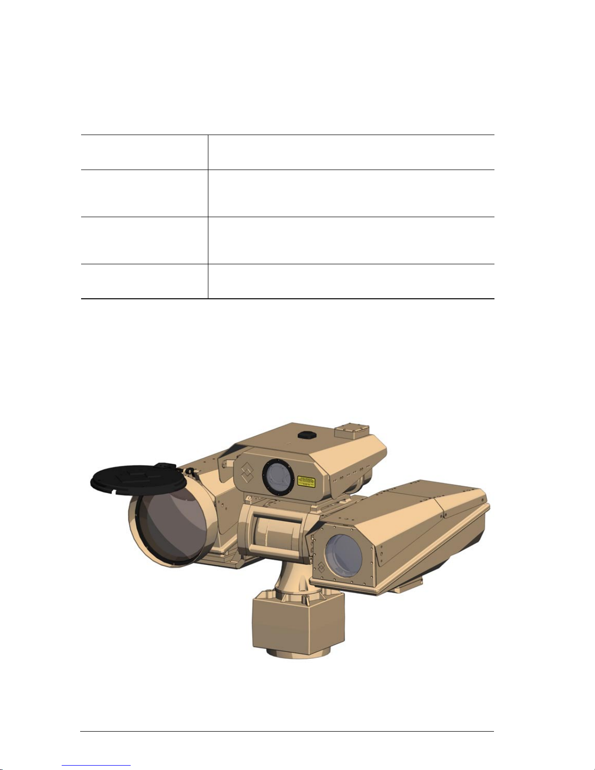
3.1.1 IR Camera
The IR Camera is equipped with a cooled mid-wave detector, which offers
long range performance in all weather conditions, through smoke and
dust. The cooled detector also makes it possible to clearly see details in
the image. The detector is designed for man-size target detection above
10 km and vehicle detection above 20 km.
The IR Camera has a continuous zoom, with clear image over the full
zoom range. As opposed to systems with a rotating lens system, there is
no switching or swapping between the different images. The operator can
gradually zoom in on a target, while keeping his focus all the time. The
camera is also equipped with a digital zoom and multiple preset eld-of-
view positions.
The IR Camera contains an auto focus feature that provides an immediate
clear and focused image. Focus to a preset distance and manual focus is
also provided.
Page 15

Ranger HRC™ operator´s manual – System description
Publ. No. TM 614 006 699 Rev B – ENGLISH (EN) – Oct 30. 2008 5
The IR Camera has a set of automatic functions that ensure a high contrast image even in the most challenging thermal conditions, such as level
and span adjustments, histogram equalization and Digital Detail Enhance-
ment processing.
The IR Camera is a rugged and sealed unit, designed for harsh environments. There are heaters for defrosting of the front lens.
3.1.2 TV Camera
The TV Camera is a sensitive, high-magnication, color quality daylight
camera, used for additional target identication when conditions permit.
The TV Camera is a standard item mounted in a rugged FLIR housing.
3.1.3 LRF
The Laser Range Finder (LRF) unit is an optional system component.
The LRF unit is a light weight eye-safe laser range nder, radiating in
the 1.54μm Erbium glass wave length. The unit consists of a laser trans-
mitter, a laser receiver, power supplies and control and signal processing
electronics.
The LRF unit determines the distance to a target by measuring the time
it takes for a laser pulse to go the target and back again. This time is con-
verted to a distance.
For more information about distance measurements, see section 11.5.
3.1.4 GPS
The Global Positioning System (GPS) unit is an optional system component.
The Global Positioning System is a network of satellites that transmit
accurate time and position information worldwide. GPS receivers receive
signals from these satellites and use the information to determine an
exact location. Satellites orbit the earth at around 12,000 miles. While a
GPS receiver can detect signals from up to 12 satellites at any time, only
Page 16

Ranger HRC™ operator´s manual – System description
6 Publ. No. TM 614 006 699 Rev B – ENGLISH (EN) – Oct 30. 2008
three signals are needed to provide a position or “GPS x” latitude and
longitude) for vehicle navigation systems.
The GPS unit is an advanced device for GPS based geomapping, which is
used to determine the exact position of the system.
The GPS unit consists of two parts, the external antenna and the internal
electronics. In order to allow the GPS antenna to receive the GPS signals,
the antenna must be outdoors with an unobstructed view of the sky. The
GPS unit can operate in all weather types, except for heavy snowfall.
3.1.5 Digital Magnetic Compass
The Digital Magnetic Compass (DMC) unit is an optional system component.
The DMC unit is a high sensitivity precision instrument, which measures
magnetic elds in three dimensions. The intention is to measure the geomagnetic eld, in order to nd magnetic north. However, also other magnetic elds near the DMC unit will be included in the result and have
effect on the readings. For that reason, it is important that the system is
placed away from any sources of magnetic interference; such as transformers, motors, radars, power lines and steel vehicles.
The geomagnetic eld also has a declination also referred to as variation
or deviation) between magnetic north and true north. Each geographical
location has its own xed declination, in the order of a few to several de-
grees. A common situation is that there also is a variable declination over
24 hours in the order of tenths of degrees. In order to nd true north, the
local magnetic declination between magnetic north and true north must
be entered into the system when the DMC unit is calibrated. A negative
number corrects toward west and a positive number towards east.
For more information about DMC calibration, see section 10.3.1.
Page 17
Ranger HRC™ operator´s manual – System description
Publ. No. TM 614 006 699 Rev B – ENGLISH (EN) – Oct 30. 2008 7
3.2 System components
In addition to the cameras and sensors, the system includes components
for pan/tilt, signal distribution, power supply, etc.
For part numbers of the cables, please refer to the Parts list in section
15.2. For an overview of the location of the connectors, see section 15.4.
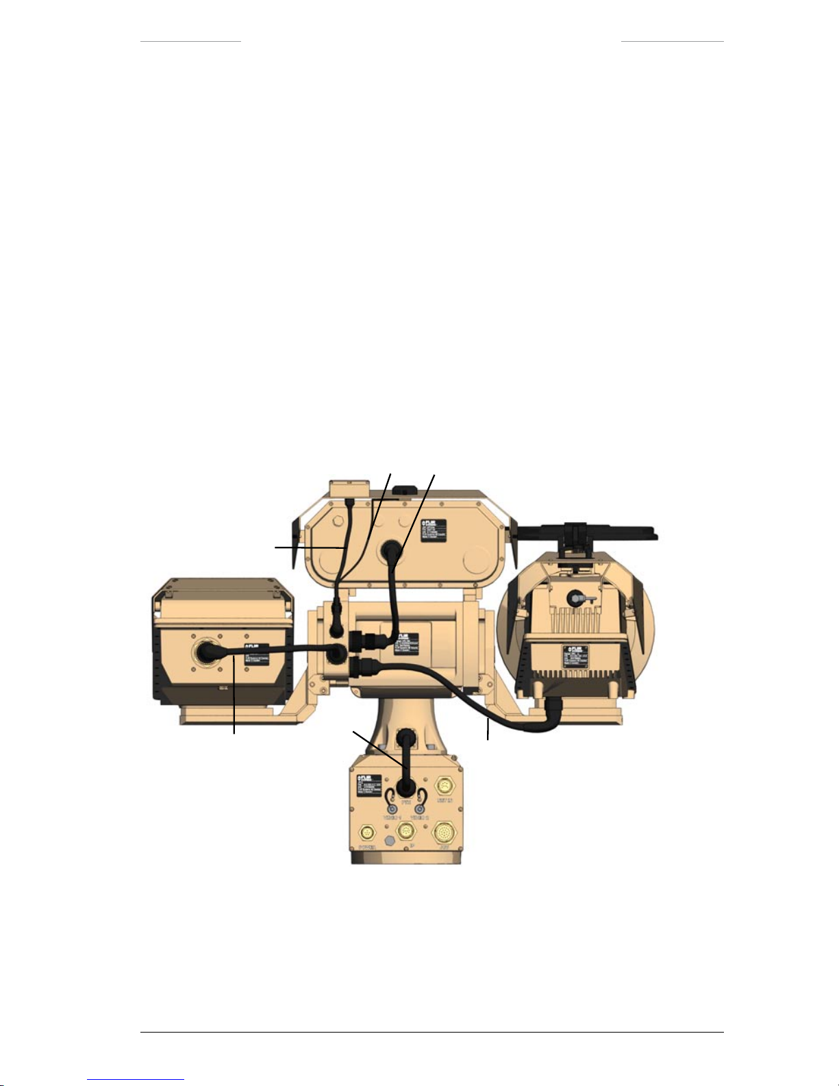
3.2.1 Pan/Tilt
The Pan/Tilt unit is a rugged two axis pan and tilt mechanism. The Pan/
Tilt unit is equipped with a left and a right mounting plate, where the IR
and TV and cameras are mounted. On top of the Pan/Tilt unit, there is a
housing for the LRF, DMC and GPS units.
1
2
3
4
5
6
Figure 3.1 Pan/Tilt connections.
Page 18

Ranger HRC™ operator´s manual – System description
8 Publ. No. TM 614 006 699 Rev B – ENGLISH (EN) – Oct 30. 2008
Pan/Tilt connections
Callout Description
1 TV camera cable
The TV Camera cable is connected to the X3 connector on the Pan/Tilt unit and to the
TV Camera.
2 IR camera cable
The IR Camera cable is connected to the X2 connector on the Pan/Tilt unit and to the
IR Camera.
3 GPS antenna cable
The GPS antenna cable is connected to the X4 connector on the Pan/Tilt unit and to
the GPS unit.
4 DMC cable
The DMC is connected to the X5 connector on the Pan/Tilt unit and to the DMC unit.
5 LRF cable
The LRF cable is connected to the X6 connector on the Pan/Tilt unit and to the LRF
unit.
6 System cable
The System cable is connected to the X1 connector on the Pan/Tilt unit and to the
PTH connector (J15) on the JPC2 unit.
Page 19
Ranger HRC™ operator´s manual – System description
Publ. No. TM 614 006 699 Rev B – ENGLISH (EN) – Oct 30. 2008 9
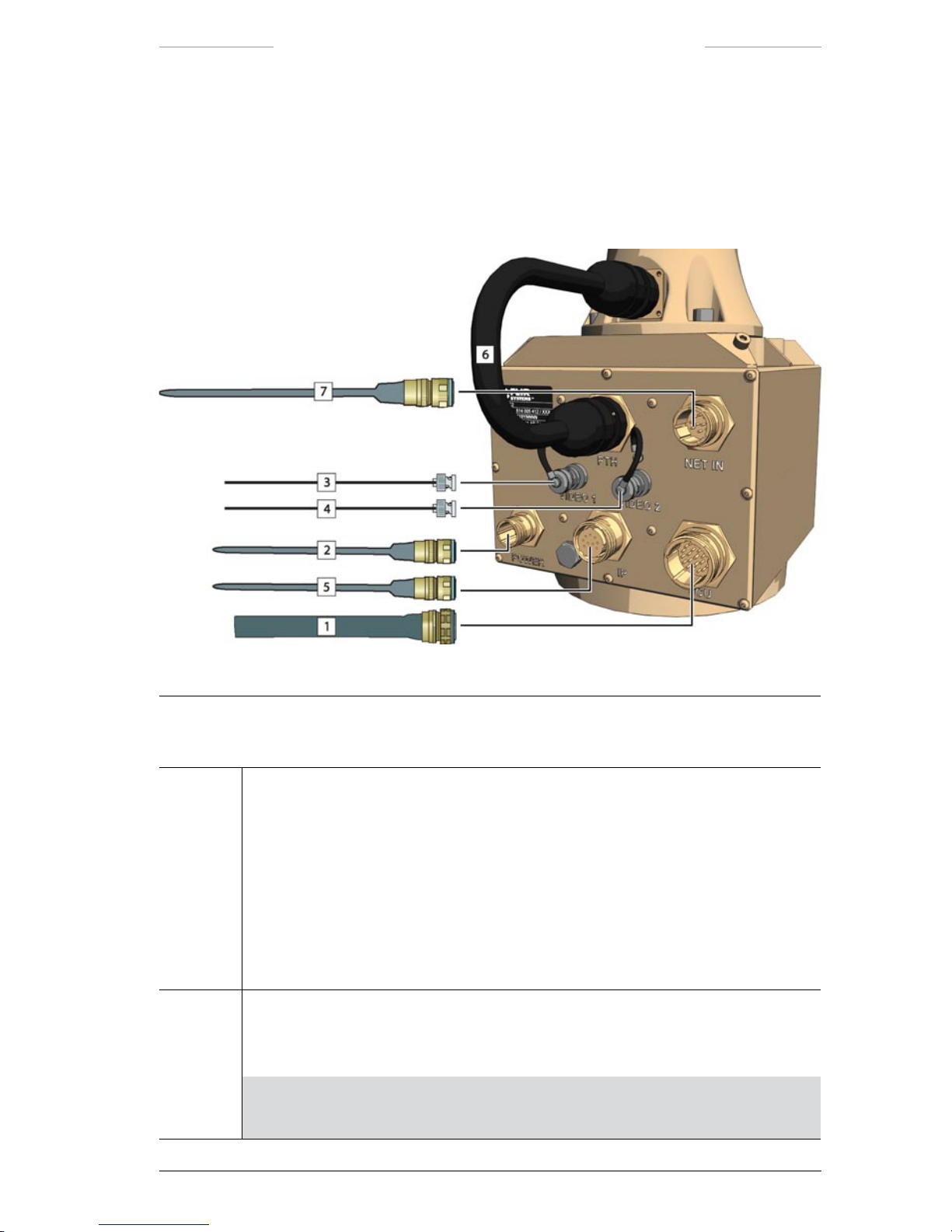
3.2.2 Junction Protocol Converter (JPC2)
The Junction Protocol Converter (JPC2) is the system control unit. The
System Software is executed from the JPC2 unit. The JPC2 can be congured for stand-alone operation or congured into an IP network.
Figure 3.2 JPC2 connections.
JPC2 connections
Callout Description
1 System cable or JCU cable
When the system is controlled from a remotely located Joystick Control Unit, the
System cable is connected to the JCU connector (J1) on the JPC2 unit and to:
• the J5 connector on the Junction Box, or
• the J5 connector on the Power Box.
When the system is controlled from a directly connected Joystick Control Unit, the
JCU cable is connected to the JCU connector (J1) on the JPC2 unit and to the J10
connector on the Joystick Control Unit.
2 Power cable
The Power cable is connected to the POWER connector (J2) on the JPC2 unit and to
the Power Supply unit.
NOTE: The POWER connector (J2) on the JPC2 unit must not be used when
power is supplied via the System cable from the Junction Box or Power Box.
Page 20

Ranger HRC™ operator´s manual – System description
10 Publ. No. TM 614 006 699 Rev B – ENGLISH (EN) – Oct 30. 2008
JPC2 connections
Callout Description
3 Video cable
The Video cable is used to connect a video monitor directly to the JPC2 unit.
The Video cable is connected the VIDEO 1 connector (J3) on the JPC2 unit.
NOTE: The VIDEO 1 connector (J3) corresponds to the J6 connector on the
Junction Box.
4 Video cable
The Video cable is used to connect a video monitor directly to the JPC2 unit.
The Video cable is connected to the VIDEO 2 connector (J11) on the JPC2 unit.
NOTE: The VIDEO 2 connector (J11) corresponds to the J7 connector on the
Junction Box.
5 Ethernet cable
The Ethernet cable is used to connect a LAN switch in an IP network to the JPC2 unit.
The Ethernet cable is connected to the IP connector (J14) on the JPC2 unit.
NOTE: The maximum cable distance between the JPC2 and the LAN switch
is 100 m/ 328 ft.
NOTE: The possibility to connect the system an IP network is an extra option.
The IP connector (J14) is only available if the IP network option has been
chosen.
6 System cable
The System cable is connected to the PTH connector (J15) on the JPC2 unit and to
the X1 connector on the Pan/Tilt unit.
7 Host cable
The Host cable is used when the system is controlled from an external computer.
The Host cable is connected to the NET IN connector (J16) on the JPC2 unit.
NOTE: The possibility to connect an external computer to the JPC2 unit is an
extra option. The NET IN connector (J16) is available on request.
Page 21
Ranger HRC™ operator´s manual – System description
Publ. No. TM 614 006 699 Rev B – ENGLISH (EN) – Oct 30. 2008 11
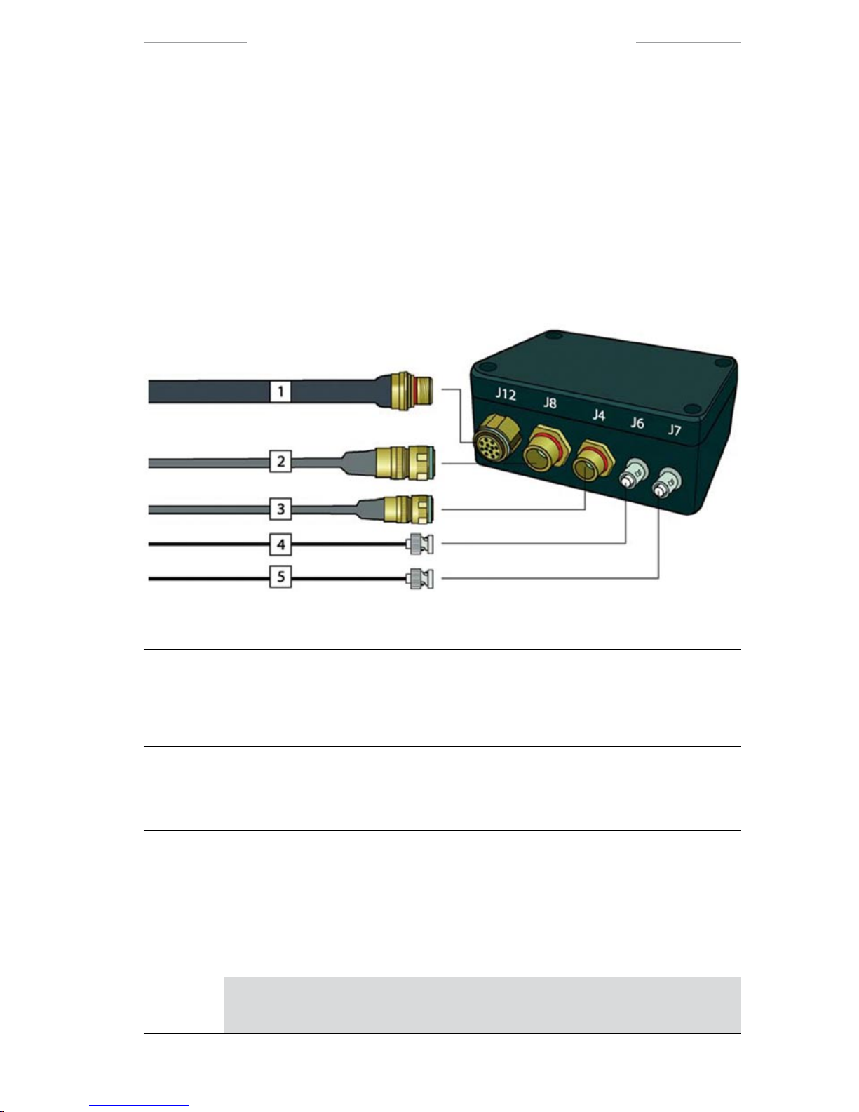
3.2.3 Junction Box
The Junction Box is the central power and signal distribution hub for the
system. Through this unit, power (+28VDC) is distributed to the main
sub systems. Command, data and control signals are distributed to the
appropriate sub systems for processing. The Junction Box also provides
interface connections to other systems, such as Host Control Systems
HOST). The Junction box has a standard set of features, such as video
output buffers and host communication signal conditioning.
Figure 3.3 Junction Box connections, front side.
Junction Box connections, front side
Callout Description
1 Reserved for future capabilities.
2 Host cable
The Host cable is used when the system is controlled from an external computer.
The Host cable is connected to the J8 connector on the Junction Box.
3 Power cable
The Power cable is connected to the J4 connector on the Junction Box and to the
Power Supply unit.
4 Video cable
The Video cable is connected to the J6 connector on the Junction Box and to an
external video monitor.
NOTE: The J6 connector corresponds to the VIDEO 1 connector (J3) on the
JPC2 unit.
Page 22
Ranger HRC™ operator´s manual – System description
12 Publ. No. TM 614 006 699 Rev B – ENGLISH (EN) – Oct 30. 2008
Junction Box connections, front side
Callout Description
5 Video cable
The Video cable is connected to the J7 connector on the Junction Box and to an
external video monitor.
NOTE: The J7 connector corresponds to the VIDEO 2 connector (J11) on
the JPC2 unit.
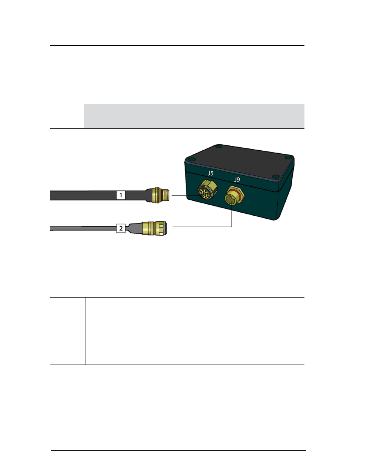
Figure 3.4 Junction box connections, rear side
Junction Box connections, rear side
Callout Description
1 System cable
The System cable is connected to the J5 connector on the Junction Box and to the
JCU connector (J1) on the JPC2 unit.
2 JCU cable
The JCU cable is connected to the J9 connector on the Junction Box and to the J10
connector on the Joystick Control Unit (JCU).
Page 23
Ranger HRC™ operator´s manual – System description
Publ. No. TM 614 006 699 Rev B – ENGLISH (EN) – Oct 30. 2008 13
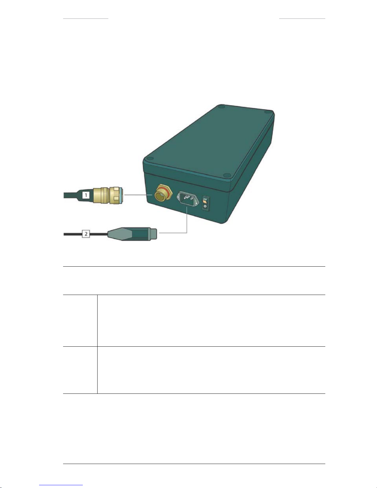
3.2.4 Power Supply
The Power Supply unit converts AC mains 85–264 VAC, 47–440 Hz)
to +28 VDC, which is used by all sub systems. The Power Supply unit is
either connected to the Junction Box or directly to the JPC2 unit.
Figure 3.5 Power Supply connections
Power Supply connections
Callout Description
1 Power cable
The Power cable is connected to the Power Supply unit and to:
• the J4 connector on the Junction Box, or
• the POWER connector (J2) on the JPC2 unit.
2 AC Mains cable
The AC Mains cable is connected to the power inlet on the Power Supply unit and to
the AC mains supply.
The Power cable is shipped either with a European or a US standard AC power plug.
Page 24
Ranger HRC™ operator´s manual – System description
14 Publ. No. TM 614 006 699 Rev B – ENGLISH (EN) – Oct 30. 2008
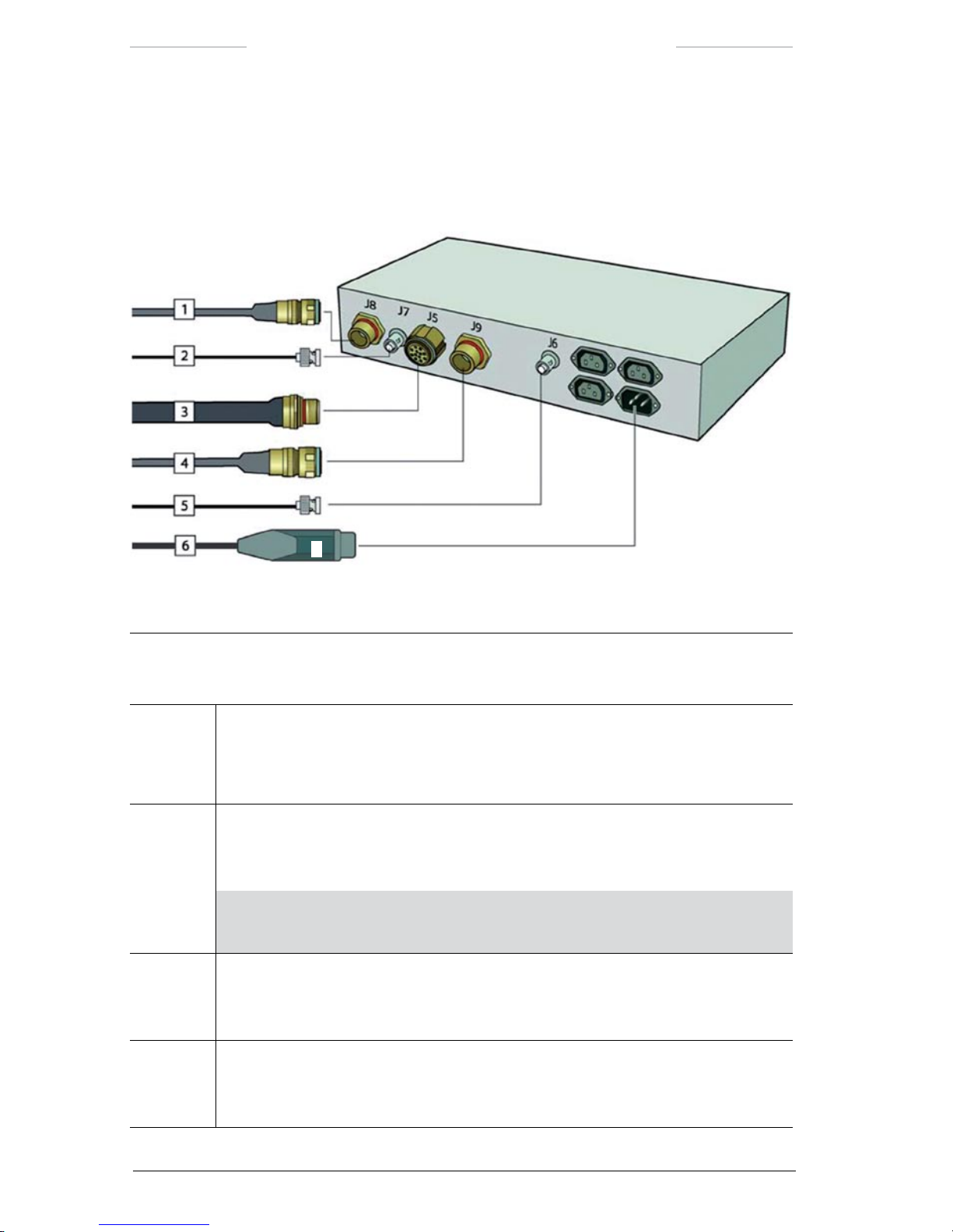
3.2.5 Power Box
The Power Box is the Junction Box and the Power Supply unit integrated
in a 19” case.
Figure 3.6 Power Box connections.
Power Box connections
Callout Description
1 Host cable
The Host cable is used when the system is controlled from an external computer.
The Host cable is connected to the J8 connector on the Power Box.
2 Video cable
The Video cable is connected to the J7 connector on the Power Box and to an external
video monitor.
NOTE: The J7 connector corresponds to the VIDEO 1 connector (J3) on the
JPC2 unit.
3 System cable
The System cable is connected to the J5 connector on the Power Box and to the JCU
connector (J1) on the JPC2 unit.
4 JCU cable
The JCU cable is connected to the J9 connector on the Power Box and to the J10
connector on the Joystick Control Unit (JCU).
Page 25

Ranger HRC™ operator´s manual – System description
Publ. No. TM 614 006 699 Rev B – ENGLISH (EN) – Oct 30. 2008 15
Power Box connections
Callout Description
5 Video cable
The Video cable is connected to the J6 connector on the Power Box and to an external
video monitor.
NOTE: The J6 connector corresponds to the VIDEO 2 connector (J11) on the
JPC2 unit.
6 AC Mains cable
The AC Mains cable is connected to the power inlet on the Power Box and to the AC
mains supply.
The Power cable is shipped either with a European or a US standard AC power plug.
NOTE: The three power outlets can be used to connect for instance the video
monitors and other equipment.
Page 26
Ranger HRC™ operator´s manual – System description
16 Publ. No. TM 614 006 699 Rev B – ENGLISH (EN) – Oct 30. 2008
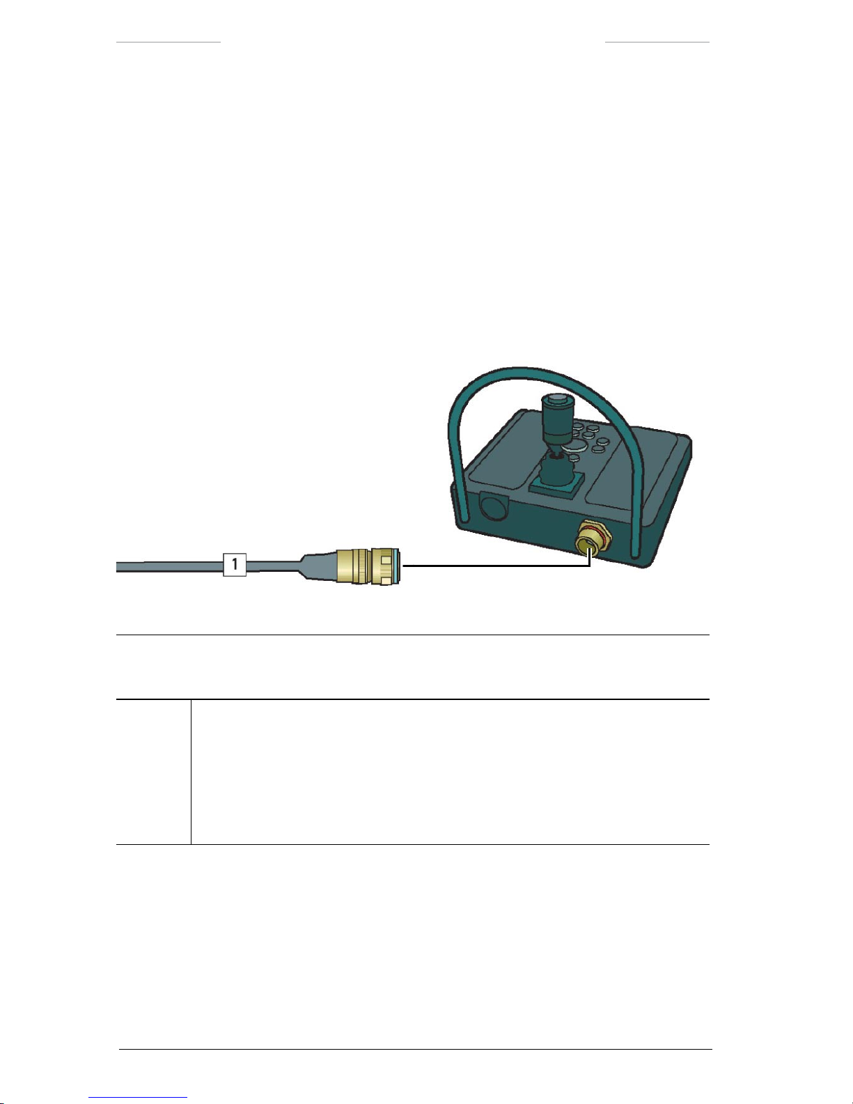
3.2.6 Joystick Control Unit
The Joystick Control Unit JCU), with its joystick and keypad buttons, is
used to control the system. The joystick provides continuously variable
cross-coupled X to Y axis) control of the system’s azimuth and elevation
position. With the keypad buttons, frequently used functions are quickly
executed. The JCU is also used to navigate in the menu system of the
System Software.
For more information about the JCU, see chapter 6.
Figure 3.7 Joystick Control Unit.
Joystick Control Unit connections
Callout Description
1 JCU cable
The JCU cable is connected to the J10 connector on the Joystick Control Unit and to:
• the JCU connector (J1) on the JPC2 unit, or
• the J9 connector on the Junction Box, or
• the J9 connector on the Power Box.
Page 27

Ranger HRC™ operator´s manual – System description
Publ. No. TM 614 006 699 Rev B – ENGLISH (EN) – Oct 30. 2008 17
3.2.7 Remote Power Controller
The external Remote Power Controller RPC) unit is an optional unit that
is used to reduce the power consumption of the system. When the system
is equipped with the RPC unit, it is possible to power off the entire system
with a simple keypad button sequence on the JCU, see section 11.1.3.
NOTE: The system has a remote power control function also without the RPC unit. However, in this case only the cameras and the sensors are powered on/off with the keypad
button sequence.
3.3 System control
The Ranger HRC MS system can be congured for stand-alone operation
or for operation in an IP network with multiple systems. With the standalone conguration, the system is controlled via the System Software running on the JPC2 unit. With the IP network conguration, a standard PC
running a security and surveillance application – such as the FLIR Nexus
application – is used to control the Ranger HRC MS systems. The Joystick Control Unit can be used in both congurations.
It is possible to access the IR Camera software, which offers advanced
features for optimization of the IR image, from both the System Software
and from the FLIR Nexus application.
The System Software is described in detail in chapter 7. The IR Camera
software is described in detail in chapter 8.
For information about the IP network conguration, see section 15.9. For
information about the FLIR Nexus application, please refer to the Nexus
manual.
Page 28
18 Publ. No. TM 614 006 699 Rev B – ENGLISH (EN) – Oct 30. 2008
4
System Congurations
The Ranger HRC MS is a modular system, which can be equipped with IR
Camera, TV Camera, optional sensors and system components.
IR cameras: Ranger HRC-U
Ranger HRC-S
TV cameras: LR-TV
UR-TV
SR-TV
Sensors: Laser Range Finder (LRF)
Digital Magnetic Compass (DMC)
GPS
System components:
JPC2
Pan/Tilt
For detailed technical data of the cameras, sensors and system components, see section 15.1.
There are six main congurations of the Ranger HRC MS system, as
shown in the gures below.
Figure 4.1 Ranger HRC-U, LR-TV, LRF, DMC, GPS, JPC2 and Pan/Tilt.
Page 29
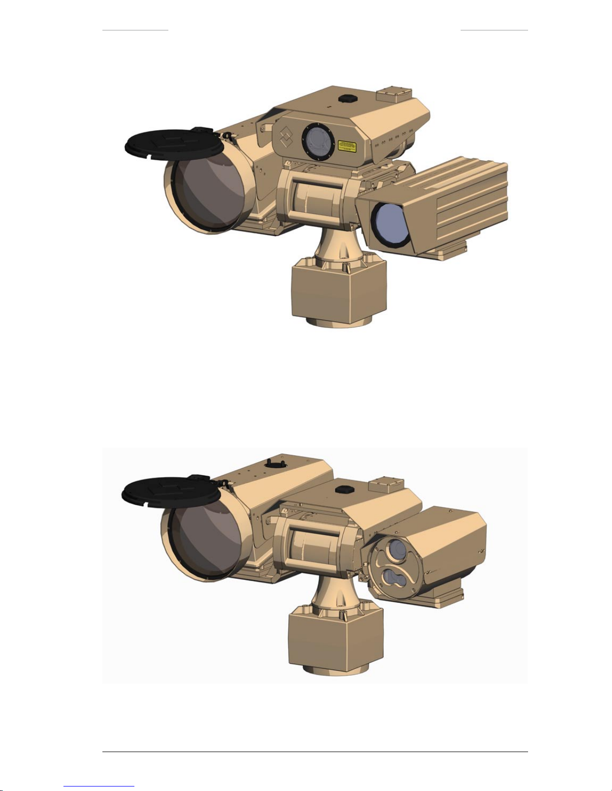
Ranger HRC™ operator´s manual – System Congurations
Publ. No. TM 614 006 699 Rev B – ENGLISH (EN) – Oct 30. 2008 19
Figure 4.2 Ranger HRC-U, UR-TV, LRF, DMC, GPS, JPC2 and Pan/Tilt.
Figure 4.3 Ranger HRC-U, SR-TV, DMC, GPS, JPC2 and Pan/Tilt.
Page 30
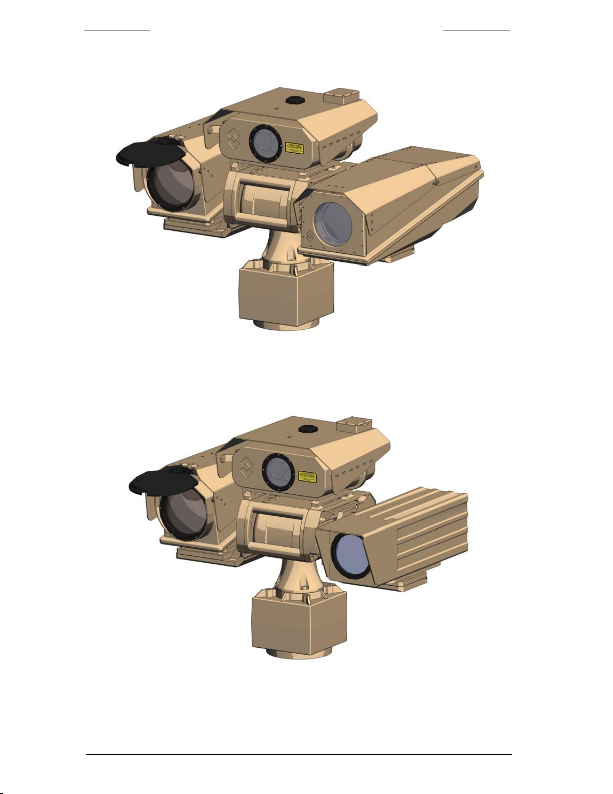
Ranger HRC™ operator´s manual – System Congurations
20 Publ. No. TM 614 006 699 Rev B – ENGLISH (EN) – Oct 30. 2008
Figure 4.4 Ranger HRC-S, LR-TV, LRF, DMC, GPS, JPC2 and Pan/Tilt.
Figure 4.5 Ranger HRC-S, UR-TV, LRF, DMC, GPS, JPC2 and Pan/Tilt.
Page 31

Ranger HRC™ operator´s manual – System Congurations
Publ. No. TM 614 006 699 Rev B – ENGLISH (EN) – Oct 30. 2008 21
Figure 4.6 Ranger HRC-S, SR-TV, DMC, GPS, JPC2 and Pan/Tilt.
Page 32

22 Publ. No. TM 614 006 699 Rev B – ENGLISH (EN) – Oct 30. 2008
5
Functions and features
This chapter provides more detailed information about some of the functions and features of the Ranger HRC MS system.
5.1 Operating modes
The Ranger HRC MS system operates in six different operating modes;
NORMAL, AUTOSCAN, PARK, LRF, MENU and PROG POSITION mode.
Each mode is a combination of settings and functions designed to assist
the operator in performing a particular task.
The functions of the joystick and the keypad buttons on the Joystick Con-
trol Unit (JCU) depend on the operating mode of the system, see chapter
6.
5.1.1 NORMAL mode
NORMAL mode is the default mode.
In NORMAL mode, the JCU is used to pan and tilt the system, to move
the system to the preset eld-of-views, to zoom in and out, to focus, etc.
5.1.2 AUTOSCAN mode
In AUTOSCAN mode, the system is automatically moved from point to
point in a preset autoscan list.
While the system is in AUTOSCAN mode, it tracks the preset position
during changes in azimuth, elevation, eld-of-view, focus and zoom set-
tings. The autoscan points are programmed when the system is in PROG
POSITION mode. It is possible to dene up to 32 autoscan points, in up to
ve autoscan lists. For instructions on programming of autoscan points
and management of autoscan lists, see section 11.4.
AUTOSCAN mode can be entered from NORMAL and PARK mode, by
pressing the SCN button on the JCU. AUTOSCAN mode can also be
entered from the menu system, with the Start autoscan feature. If auto-
scanning is started by pressing the SCN button, the system will resume
Page 33

Ranger HRC™ operator´s manual – Functions and features
Publ. No. TM 614 006 699 Rev B – ENGLISH (EN) – Oct 30. 2008 23
the autoscan from the currently selected autoscan point (if the scan was
previously stopped or if the operator has used the LEFT/RIGHT buttons
to step through the different positions). When AUTOSCAN mode is ente-
red from the menu system, autoscanning will start with the rst autoscan
point in the current autoscan list. If no autoscan points have been de-
ned, it is not possible to enter AUTOSCAN mode.
When the system is in AUTOSCAN mode, “Autoscan” is displayed in the
upper left corner of the monitor.
5.1.3 PARK mode
In the PARK mode, the system is parked either in the home position or in
the mechanical home position.
The home position is dened by the operator. It can for example be true
north, which is obtained with a calibration of the Digital Magnetic Compass DMC), or a specic target, such as a gateway or an entrance door.
For instructions on how to dene the home position, see section 10.3.
When the system is in the mechanical home position, the cameras and
sensors are directed straight forwards. This position is recommended before the system is turned off.
When the PRK button is pressed > 1 second, the system is sent to the
mechanical home position, the lens cover of the IR camera is closed and
PARK mode is entered.
When the PRK button is pressed < 1 second, the system is sent to the
home position. If the PRK button is pressed < 1 second again when the
system is in home position, the lens cover of the IR camera is closed and
PARK mode will be entered.
PARK mode can also be entered from the menu system. The Park pan/tilt
feature in the Pan/Tilt menu sends the system to the home position. If
the Park pan/tilt feature is selected a second time when the system is in
home position, the lens cover is closed and PARK mode is entered
When the system is in PARK mode, “Parked” is displayed in the center of
the monitor.
Page 34

Ranger HRC™ operator´s manual – Functions and features
24 Publ. No. TM 614 006 699 Rev B – ENGLISH (EN) – Oct 30. 2008
5.1.4 LRF mode
When the system is in LRF mode, the Laser Range Finder (LRF) unit is
active and can be used to measure the distance to a target.
For instructions on how to measure distances with the LRF unit, see sec-
tion 11.5.
LRF mode is entered by pressing the FCN + INV buttons simultaneously
in NORMAL mode or by selecting the Activate laser feature in the LRF
menu.
When the system is in LRF mode, “Laser ready”, “Laser charging” or
“Laser not ready” is displayed in the upper left corner of the monitor.
5.1.5 MENU mode
When the system is in MENU mode, the menu system of the System Software is displayed, which gives access to the features of the system. The
JCU is used to navigate in the menu system and to execute actions.
MENU mode is entered by pressing the ENTER button in NORMAL or
PARK mode.
5.1.6 PROG POSITION mode
When the system is in PROG POSITION mode, new autoscan points can
be dened and existing points can be edited.
For instructions on how to dene and edit autoscan points, see section
11.4.
PROG POSITION mode is entered by pressing the FCN button in AUTO-
SCAN mode or via the Go to position…feature in the Pan/Tilt menu.
When the system is in PROG POSITION mode, “Prog position” is dis-
played in the upper left corner of the monitor.
Page 35

Ranger HRC™ operator´s manual – Functions and features
Publ. No. TM 614 006 699 Rev B – ENGLISH (EN) – Oct 30. 2008 25
5.2 IR image optimization
The quality of the IR image depends on many factors, such as target temperature, ambient temperature, distance to target, etc. The IR Camera
has a number of functions – automatic and manual – that are used to
control the image quality.
5.2.1 Non-Uniformity Correction
Non-Uniformity Correction NUC) is a function that performs an internal
calibration of the IR camera.
NUC can be performed in three different ways. With Internal NUC, the
image is calibrated against a shutter inside the camera (Internal shutter).
With External NUC, either the lens cover External shutter) or the scene
(Shutter off) is used as thermal reference.
The normal procedure is to start with an Internal NUC. If an acceptable
image quality is not achieved, an External NUC against the lens cover or
against the scene may improve the image.
At startup of the system, NUC has to be performed frequently every 5
minutes) as the temperature of the IR Camera changes. After about
30 minutes, NUC is only needed when the quality of the image is
degenerated.
5.2.2 Adjustment area
The IR Camera automatically adjusts the image based on the scene contents. By selecting different adjustment areas, it is possible to control
which part of the scene that shall be used when adjusting the image.
The selected area has an impact on the adjustments of level brightness),
span contrast) and color distribution, as illustrated in the gures below.
Page 36

Ranger HRC™ operator´s manual – Functions and features
26 Publ. No. TM 614 006 699 Rev B – ENGLISH (EN) – Oct 30. 2008
Figure 5.1 Adjust Area 1. Figure 5.3 Adjust Area 2.
Figure 5.2 Adjust Area 3. Figure 5.4 Adjust Area 4.
Figure 5.5 Adjust Area 5.
Page 37

Ranger HRC™ operator´s manual – Functions and features
Publ. No. TM 614 006 699 Rev B – ENGLISH (EN) – Oct 30. 2008 27
5.2.3 Adjustment modes
There are four adjustment modes selectable via the IR Camera menu system; Auto Level, Auto Level-Span, DDE and Manual.
In Auto Level mode, level is automatically adjusted.
In Auto Level-Span mode, both level and span are automatically
adjusted.
DDE Digital Detail Enhancement) is an automatic adjustment mode
for level and span, which also enhances the visibility of details in the
scene.
In Manual mode, level and span adjustments are made manually.
The most suitable mode depends on many factors. Auto mode normally
gives a good image quality, but in scenes with low or high contrast DDE
and/or Manual mode may be better.
5.2.4 Adjust image
Adjust image is a feature that allows manual adjustments of the image
with regards to level and span, or the corresponding brightness and contrast.
In Auto Level-Span and DDE mode, level and span are automatically adjusted. The Adjust image feature makes it possible to tune the automatic
values, by adjusting brightness and contrast with a percentage offset.
In Auto Level mode, level is automatically adjusted. The Adjust image
feature is used to manually adjust the span value. The Adjust image feature also makes it possible to tune the automatic level value, by adjusting
brightness with a percentage offset.
In Manual mode, both level and span are adjusted manually. Frequent
adjustments and ne-tuning are needed to achieve a good image quality.
Page 38

Ranger HRC™ operator´s manual – Functions and features
28 Publ. No. TM 614 006 699 Rev B – ENGLISH (EN) – Oct 30. 2008
5.2.5 Color Distribution
There are two Color Distribution modes; Linear and Histogram.
In Linear mode, the colors are distributed linearly from the darkest
to the brightest pixel in the image.
In Histogram mode, the colors are distributed based on the contents
of the image.
The Histogram mode normally gives the best image, but for small details
the Linear mode may be better. The Linear mode also gives a more intuitive perception of the temperature contents.
5.2.6 Digital Detail Enhancement
Digital Detail Enhancement (DDE) is a function that enhances the visibility of details in the IR image.
In principle, DDE separates the image signal into two parts:
The background image, which contains the low frequency, high amp-
litude part if the image.
The detail image, which contains the high frequency, low amplitude
part of the image.
The two parts can be scaled separately, before they are merged to produce
an output image. This allows the system to output an image where ne
details are visible even in a very high dynamic range scene.
Page 39
Ranger HRC™ operator´s manual – Functions and features
Publ. No. TM 614 006 699 Rev B – ENGLISH (EN) – Oct 30. 2008 29
Figure 5.6 DDE turned off.
Figure 5.7 DDE turned on.
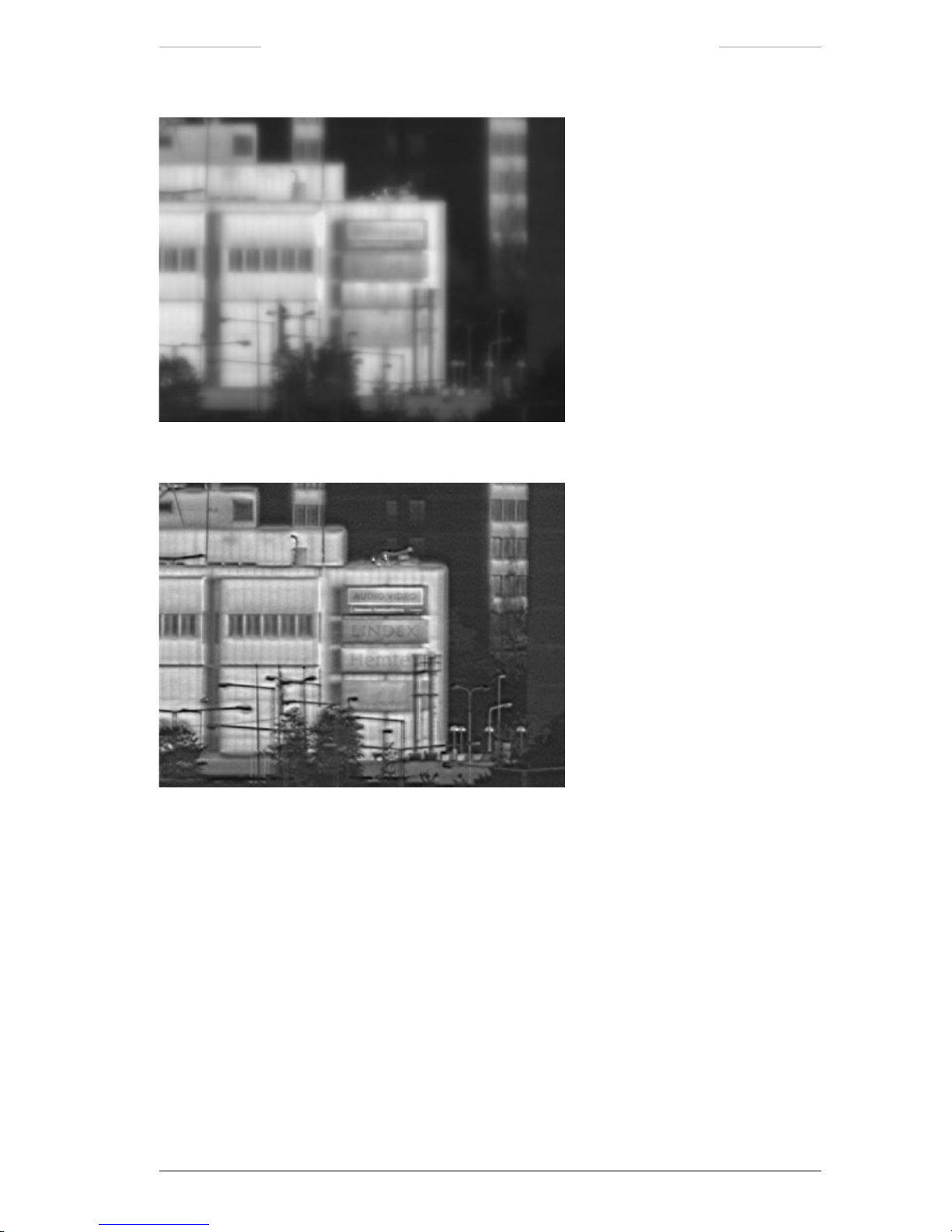
5.2.7 DDE lter
The DDE lter enables control of details, separated from the control of
the dynamic range of the background. The lter operates as a powerful
noise lter at one end and as very strong detail enhancing lter at the
other end.
The DDE Control feature allows tuning of the DDE lter. The setting of
the DDE ltering function 1-100%) allows a continuous control from
softening lter with noise reduction low value) to sharpening lter with
detail enhancement (high value).
Page 40
Ranger HRC™ operator´s manual – Functions and features
30 Publ. No. TM 614 006 699 Rev B – ENGLISH (EN) – Oct 30. 2008
The DDE Control setting under normal conditions is a matter of personal
taste. In low contrast scenes, for example in rainy and foggy weather, a
low DDE Control value is recommended 0–20). In high contrast scenes,
for example a sunny day in the desert, a high DDE Control value is recommended 60–100). The default DDE Control value is 60.
Figure 5.8 DDE is turned off.
Figure 5.9 DDE is set to 1%. Noise and ne details are removed.
Figure 5.10 DDE is set to 70%.
Page 41

Ranger HRC™ operator´s manual – Functions and features
Publ. No. TM 614 006 699 Rev B – ENGLISH (EN) – Oct 30. 2008 31
Figure 5.11 DDE set to 100%. The lter functions as an extreme detail booster.
5.2.8 Filter
Filter is a function that reduces the noise visible in the image in low contrast scenes. Low and high ltering is available
Normally the Filter shall be set to Off. In low contrast scenes, the Filter
shall be set to Low or High to improve the image.
Filtering is normally not suitable for moving targets, as it may cause
smearing in the image presentation.
5.2.9 IR palette
There are four different IR palettes:
Rainbow
Rainbow HC
Gray
Iron
The default IR palette is Gray. Changing the palette from Gray to Rainbow may improve the perception of details in low contrast scenes.
All IR palettes are possible to invert. With the Gray palette for example,
white or black can be set to represent hot whitehot is default). Inverting
the palette may have an effect on how the image is perceived.
Page 42

Ranger HRC™ operator´s manual – Functions and features
32 Publ. No. TM 614 006 699 Rev B – ENGLISH (EN) – Oct 30. 2008
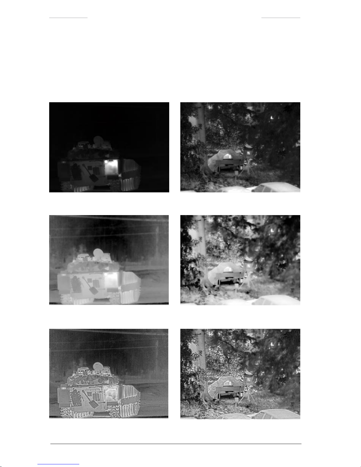
5.2.10 Zoom interpolation
Zoom interpolation is a function that has effect when the digital zoom is
used.
Interpolation is a mathematical process used to estimate values between
known point observations. The camera software interpolates the resolution by mathematically analyzing what would be the most plausible value
of the closest neighbor of a pixel.
Zoom interpolation On gives a smoother image.
Zoom interpolation Off gives a pixilated image.
The default setting of Zoom interpolation is On.
Figure 5.12 Digital zoom with interpolation turned on (upper right image) and
with interpolation turned off (lower right image).
Page 43
Publ. No. TM 614 006 699 Rev B – ENGLISH (EN) – Oct 30. 2008 33
6
Joystick Control Unit
The Joystick Control Unit JCU), with its joystick and keypad buttons, is
used to control the Ranger HRC MS system.
6.1 Overview
The main parts of the Joystick Control Unit are the joystick with a rotating collar and a push button) and the keypad with push buttons. All buttons are back-lit for operator convenience. There is also a control for the
backlight and two LED indicators.
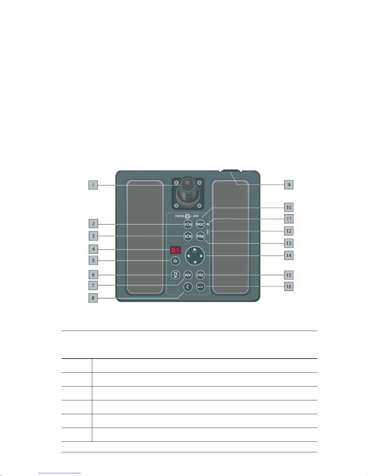
Figure 6.1 Joystick Control Unit.
Joystick Control Unit
Callout Description
1 Joystick with rotating collar and push button.
2 FCN button
3 SCN button
4 Reserved for future capabilities.
5 Reserved for future capabilities.
6 TV/IR button
Page 44

Ranger HRC™ operator´s manual – Joystick Control Unit
34 Publ. No. TM 614 006 699 Rev B – ENGLISH (EN) – Oct 30. 2008
Joystick Control Unit
Callout Description
7 INV button
8 C button/CANCEL button
9 Backlight control. Turn the control left/right to increase/decrease the backlight of the
push buttons.
10 NUC button
11 Status indicator for communication between the Joystick Control Unit and the imaging
unit. At start up, the indicator has a ashing light. During normal use, the light is
steady.
12 System heater indicator. If the system heaters are on, the indicator is lit.
13 PRK button
14 Navigation keypad
15 FRZ button
16 ENTER button
6.2 Joystick and keypad buttons
The functions of the joystick and the keypad buttons depend on the sys-
tem mode. The functions for the NORMAL, AUTOSCAN, PARK, LRF,
MENU and PROG POSITION modes are described in the tables below.
For more information about the system operating modes, see section 5.1.
6.2.1 NORMAL mode
NORMAL mode is the default mode.
There are two different settings for the JCU – Original and Alternative
– with somewhat different functions for the joystick and the keypad buttons. The setting is made in the Setup – Maintenance dialog box, see sec-
tion 7.6.1.6. The functions for both the Original and the Alternative set-
tings are described in the table.
Page 45

Ranger HRC™ operator´s manual – Joystick Control Unit
Publ. No. TM 614 006 699 Rev B – ENGLISH (EN) – Oct 30. 2008 35
JCU joystick and keypad – NORMAL mode
Feature ORIGINAL setting ALTERNATIVE setting
Joystick Move the joystick to the left/right to pan the system left/right.
Move the joystick forwards/backwards to tilt the system up/down.
NOTE: The default tilt behavior (above) can be inverted in the Setup
-Pan/Tilt dialog box, see section 7.6.1.3.
Joystick collar Turn the joystick collar to the
left/right to focus near/far.
Turn the joystick collar to the left/right
to zoom out/in.
Press the
FCN button and turn the
joystick collar to the left/right to focus
near/far.
Joystick button
Press the joystick button < 1 second
to go to the next eld-of-view.
Press the joystick button > 1
second
toggle between Slave mode
on/off, see section 7.5.1.
Press the joystick button < 1
second
to perform a one-shot auto focus
adjustment.
Press the joystick button > 1
second
to
toggle between Slave mode on/off, see
section 7.5.1.
FCN
Button FCN is used together with other buttons to provide additional functionality.
SCN Press the SCN button to enter AUTOSCAN mode. If there are no autoscan
points, there will be no action.
ID Reserved for future capabilities.
TV/IR Press the TV/IR button to toggle between TV imaging and IR imaging.
INV Press the INV button to toggle between White hot and Black hot IR palette.
Press the
FCN + INV buttons to activate the LRF unit and enter LRF mode.
C Button C is used together with other buttons to provide additional functionality.
NUC Press the NUC button < 1
second
to perform an Internal NUC.
Press the
NUC button > 1
second
to perform a one-shot auto focus adjustment.
Press the
FCN + NUC buttons < 1
second
to perform an External NUC against
the lens cover.
Press the
FCN + NUC buttons > 1
second
to go to the xed focus position.
Press the
C + NUC buttons < 1
second
to perform an External NUC against the
scene.
Press the
C + NUC buttons > 1
second
to perform a one-shot auto focus
adjustment.
NOTE: The default behavior (above) of the NUC, FCN + NUC and C + NUC
buttons can be inverted in the
Setup-Image dialog box, see section 7.6.1.1.
Page 46

Ranger HRC™ operator´s manual – Joystick Control Unit
36 Publ. No. TM 614 006 699 Rev B – ENGLISH (EN) – Oct 30. 2008
JCU joystick and keypad – NORMAL mode
Feature ORIGINAL setting ALTERNATIVE setting
PRK
Press the PRK button < 1
second
to send the system to the home position. If the
PRK button is pressed < 1
second
again when the system is in home position,
the lens cover of the IR Camera will be closed and PARK mode will be entered,
see section 5.1.3.
Press the PRK button > 1
second
to send the system to the mechanical home
position, close the lens cover of the IR Camera and enter PARK mode, see
section 5.1.3.
NOTE: At system start up, the PRK button has to be pressed for more
than 3 seconds to activate the Pan/Tilt unit.
Press the button to zoom in.
Press the
button to zoom out.
When the adjustment mode is set to
DDE (linear or full), see section 11.3.2:
Press and hold down the button to
increase the DDE value.
Press and hold down the
button to
decrease the DDE value.
If the adjustment mode is set to AUTO
(linear of full) or MANUAL, the
and
buttons have no function.
Press and hold down the
FCN + buttons to increase the level value.
Press and hold down the
FCN + buttons to decrease the level value.
NOTE: When the level value is changed, the system enters the Manual
adjustment mode, see section 11.3.2.
Press the C + buttons to manually open the lens cover.
Press the
C + buttons to manually close the lens cover.
Press the button to go to previous active autoscan point position.
Press the
button to go to next active autoscan point position.
If there are no autoscan points, there will be no action.
NOTE: This function of the buttons can be disabled, see section 7.6.1.3.
Press and hold down the FCN + buttons to decrease the span value.
Press and hold down the
FCN + buttons to increase the span value.
NOTE: When the span value is changed, the system enters the Manual
adjustment mode, see section 11.3.2.
FRZ Press the FRZ button to freeze/unfreeze the image.
ENTER
Press the ENTER button to enter MENU mode.
Page 47

Ranger HRC™ operator´s manual – Joystick Control Unit
Publ. No. TM 614 006 699 Rev B – ENGLISH (EN) – Oct 30. 2008 37
6.2.2 AUTOSCAN mode
The AUTOSCAN mode is entered by pressing the SCN button in NORMAL or PARK mode. If no autoscan points have been dened, the system
will stay in NORMAL or PARK mode when the SCN button is pressed.)
JCU joystick and keypad – AUTOSCAN mode
Feature Description
Joystick Move the joystick in any direction to enter NORMAL mode.
FCN Press the FCN button to enter PROG POSITION mode.
SCN No function in AUTOSCAN mode.
ID Reserved for future capabilities.
TV/IR Press the TV/IR button to toggle between TV imaging and IR imaging.
INV Press the INV button to toggle between White hot and Black hot IR palette.
C Press the C button to enter NORMAL mode.
NUC Press the NUC button < 1
second
to perform an Internal NUC.
Press the NUC button > 1
second
to perform a one-shot auto focus adjustment.
Press the
FCN + NUC buttons < 1
second
to perform an External NUC against the
lens cover.
Press the FCN + NUC buttons > 1
second
to go to the xed focus position.
Press the
C + NUC buttons < 1
second
to perform an External NUC against the
scene.
Press the C + NUC buttons > 1
second
to perform a one-shot auto focus adjustment.
NOTE: The default behavior (above) of the NUC and FCN + NUC buttons can
be inverted in the
Setup-Image dialog box, see section 7.6.1.1.
PRK Press the PRK button < 1
second
to send the system to the home position. If the
PRK button is pressed < 1
second
again when the system is in home position, the
lens cover of the IR Camera will be closed and PARK mode will be entered, see
section 5.1.3.
Press the
PRK button > 1
second
to send the system to the mechanical home posi-
tion, close the lens cover of the IR Camera and enter PARK mode, see section 5.1.3.
NOTE: At system start up, the PRK button has to be pressed for more than 3
seconds to activate the Pan/Tilt unit.
No function in AUTOSCAN mode.
Page 48

Ranger HRC™ operator´s manual – Joystick Control Unit
38 Publ. No. TM 614 006 699 Rev B – ENGLISH (EN) – Oct 30. 2008
JCU joystick and keypad – AUTOSCAN mode
Feature Description
Press the button to go to previous active autoscan point position and then enter
NORMAL mode.
Press the
button to go to next active autoscan point position and then enter
NORMAL mode.
NOTE: This function of the buttons can be disabled in the Setup-Pan/Tilt
dialog box, see section 7.6.1.3.
FRZ Press the FRZ button to freeze/unfreeze the image.
ENTER
No function in AUTOSCAN mode.
6.2.3 PARK mode
The PARK mode is entered by pressing the PRK button in NORMAL,
AUTOSCAN or PROG POSITION mode.
In PARK mode, most keypad buttons are disabled. These are not included
in the table below.
JCU joystick and keypad – PARK mode
Feature Description
Joystick Move the joystick in any direction to return to NORMAL or PROG POSITION mode.
SCN Press the SCN button to return to AUTOSCAN mode.
ENTER
Press the ENTER button to enter MENU mode.
Page 49

Ranger HRC™ operator´s manual – Joystick Control Unit
Publ. No. TM 614 006 699 Rev B – ENGLISH (EN) – Oct 30. 2008 39
6.2.4 LRF mode
The LRF mode is entered by pressing the FCN + INV buttons simultaneously in NORMAL mode.
In LRF mode, most buttons are disabled. These are not included in the
table below.
JCU joystick and keypad – LRF mode
Feature Description
SCN Press the FCN + SCN buttons to re a shot, see section 11.5.2.
C Press the C button to deactivate the LRF unit and exit the LRF mode.
NUC Press the NUC button < 1
second
to perform an Internal NUC.
Press the
NUC button > 1
second
to perform a one-shot auto focus adjustment.
Press the
FCN + NUC buttons < 1
second
to perform an External NUC against the
lens cover.
Press the
FCN + NUC buttons > 1
second
to go to the xed focus position.
Press the
C + NUC buttons < 1
second
to perform an External NUC against the
scene.
Press the
C + NUC buttons > 1
second
to perform a one-shot auto focus adjustment.
NOTE: The default behavior (above) of the NUC, FCN + NUC and C + NUC buttons
can be inverted in the Setup- Image dialog box, see section 7.6.1.1.
Page 50

Ranger HRC™ operator´s manual – Joystick Control Unit
40 Publ. No. TM 614 006 699 Rev B – ENGLISH (EN) – Oct 30. 2008
6.2.5 MENU mode
The MENU mode is entered by pressing the ENTER button in NORMAL
or PARK mode.
In MENU mode, certain keypad buttons are used to navigate in the Sys-
tem Software menu system. The other buttons are disabled and are not
included in the table below.
JCU joystick and keypad – MENU mode
Feature Description
ENTER
Use the ENTER button to:
• enter the MENU mode
• open the dialog box of the highlighted feature
• activate the highlighted feature and exit MENU mode
C
CANCEL
Use the CANCEL button to:
• exit the active dialog box
• exit MENU mode without changing the current menu settings
UP
DOWN
Use the UP/DOWN navigation buttons to navigate up/down in menus and dialog
boxes.
LEFT
RIGHT
Use the LEFT/RIGHT navigation buttons to:
• navigate left/right in the Main menu
• display different dialog box options
• change values in dialog boxes
NOTE: Hold down the LEFT/RIGHT button for a while to decrease/increase a
value with larger increments.
FCN The FCN button is used in some dialog boxes to enable certain actions.
Page 51

Ranger HRC™ operator´s manual – Joystick Control Unit
Publ. No. TM 614 006 699 Rev B – ENGLISH (EN) – Oct 30. 2008 41
JCU joystick and keypad – MENU mode
Feature Description
NUC Press the NUC button < 1
second
to perform an Internal NUC.
Press the
NUC button > 1
second
to perform a one-shot auto focus adjustment.
Press the
FCN + NUC buttons < 1
second
to perform an External NUC against the
lens cover.
Press the
FCN + NUC buttons > 1
second
to go to the xed focus position.
Press the
C + NUC buttons < 1
second
to perform an External NUC against the
scene.
Press the
C + NUC buttons > 1
second
to perform a one-shot auto focus
adjustment.
NOTE: The default behavior (above) of the NUC, FCN + NUC and C + NUC but-
tons can be inverted in the Setup- Image dialog box, see section 7.6.1.1.
6.2.6 PROG POSITION mode
The PROG POSITION mode is entered by pressing the FCN button in
AUTOSCAN mode. The PROG POSITION mode can also be entered from
the System Software menu system.
NOTE: For full functionality of the JCU when programming autoscan points, the MMI
Control mode in the Setup – Maintenance dialog box shall be set to Original, see section
7.6.1.6.
JCU joystick and keypad – PROG POSITION mode
Feature Description
Joystick Move the joystick to the left/right to pan the system left/right.
Move the joystick forwards/backwards to tilt the system up/down.
Joystick
collar
Turn the joystick collar to the left/right to focus near/far.
Joystick
button
Press the joystick button < 1
second
to go to the next eld-of-view.
Press the joystick button > 1
second
toggle between Slave mode on/off, see
section 7.5.1.
FCN Press the FCN button to open the Edit pos # dialog box, see section 7.4.1.2.2.
SCN No function in PROG POSITION mode.
ID Reserved for future capabilities.
TV/IR Press the TV/IR button to toggle between TV imaging and IR imaging.
Page 52
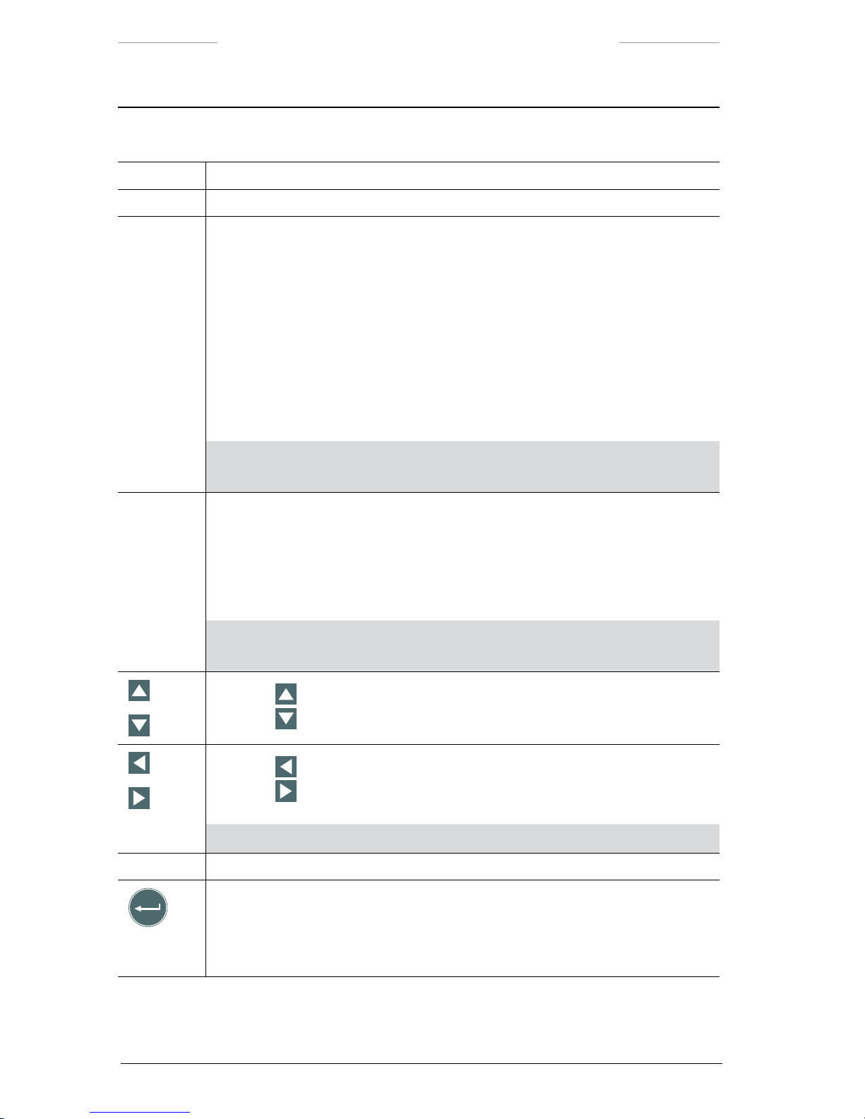
Ranger HRC™ operator´s manual – Joystick Control Unit
42 Publ. No. TM 614 006 699 Rev B – ENGLISH (EN) – Oct 30. 2008
JCU joystick and keypad – PROG POSITION mode
Feature Description
INV Press the INV button to toggle between White hot and Black hot IR palette.
C Press the C button to quit programming and enter NORMAL mode.
NUC Press the NUC button < 1
second
to perform an Internal NUC.
Press the
NUC button > 1
second
to perform a one-shot auto focus adjustment.
Press the
FCN + NUC buttons < 1
second
to perform an External NUC against the
lens cover.
Press the
FCN + NUC buttons > 1
second
to go to the xed focus position.
Press the
C + NUC buttons < 1
second
to perform an External NUC against the
scene.
Press the
C + NUC buttons > 1
second
to perform a one-shot auto focus
adjustment.
NOTE: The default behavior (above) of the NUC, FCN + NUC and C + NUC but-
tons can be inverted in the Setup- Image dialog box, see section 7.6.1.1.
PRK Press the PRK button < 1
second
to send the system to the home position. If the
PRK button is pressed < 1
second
again when the system is in home position, the
lens cover of the IR Camera will be closed and PARK mode will be entered, see
section 5.1.3.
Press the
PRK button > 1
second
to send the system to the mechanical home posi-
tion, close the lens cover of the IR Camera and enter PARK mode, see section 5.1.3.
NOTE: At system start up, the PRK button has to be pressed for more than
3 seconds to activate the Pan/Tilt unit.
Press the button to zoom in.
Press the
button to zoom out.
Press the button to go to previous active autoscan point position.
Press the
button to go to next active autoscan point position.
If there are no autoscan points, there will be no action.
NOTE: This function of the buttons can be disabled, see section 7.6.1.3.
FRZ Press the FRZ button to freeze/unfreeze the image.
ENTER
Press the ENTER button to open the New pos # dialog box, see section 7.4.1.2.1.
Page 53

Publ. No. TM 614 006 699 Rev B – ENGLISH (EN) – Oct 30. 2008 43
7
System software
The System Software is used to control the Ranger HRC MS system.
The System Software menus give access to the system features and make
it possible to enter or change system constants and values. The software
also provides the operator with information about the system.
This chapter describes features available in the System Software version
1.4.5.
7.1 System information
System information is displayed on top of the IR or TV image on the moni-
tor.
The system information is mode and function dependent. It is possible to
select which information to display. It is also possible to temporarily hide
the system information.
Figure 7.1 System information.
13
1
2
3
4
5
6
12
11
10
9
8
7
14
Page 54

Ranger HRC™ operator´s manual – System software
44 Publ. No. TM 614 006 699 Rev B – ENGLISH (EN) – Oct 30. 2008
System information
Callout Description
1 The Autoscan point number indicator (1 through 32) shows the locations of any
currently set autoscan points.
2 The FOV brackets indicator shows the image area that will be covered by the next eld-
of-view (FOV). When the next FOV is the widest FOV, no FOV brackets are shown.
3 The Crosshair reticle indicator shows the center of the current eld-of-view. When
autoscan points are being set, the Crosshair reticle shows the location of the point
to be entered.
4 The Image polarity indicator indicates if white or black is set to represent hot.
5 The System date indicator shows the date, in the format dened in the Setup menu,
see section 7.6.1.4.
6 The System time indicator shows the time, in the format dened in the Setup menu;
see section 7.6.1.4.
7 The Digital azimuth indicator provides a numeric readout of the system’s azimuth,
relative to the reference position entered in the Setup – Pan/Tilt dialog box, see section
7.6.1.3.
8 The Digital elevation indicator provides a numeric readout of the system’s elevation.
9 The Analog elevation indicator provides a graphical presentation of the system’s
elevation.
10 The Analog azimuth indicator provides a graphical presentation of the system’s azimuth,
relative to the reference position entered in the Setup – Pan/Tilt dialog box. The indicator
looks like a small clock, with the reference position at 12.
11 The Focus position indicator provides an indication of the focus travel, from near (left)
to distant (right).
12 The Active channel indicator is shown on the screen to indicate which channel –
TV or IR – that is active.
13 The Status text indicator displays status information for various functions, when these
are trigged. See section 7.1.1.
When no other status information is displayed, the
GPS indicator shows the present
position of the system in DMS format (Degree, Minute, Second); °N/S + °W/E. If the
received antenna signal is too weak or if fewer than three satellites are found, the status
text “Searching GPS” is displayed.
14 The FOV indicator provides a numeric readout of the current eld-of-view (FOV).
Page 55

Ranger HRC™ operator´s manual – System software
Publ. No. TM 614 006 699 Rev B – ENGLISH (EN) – Oct 30. 2008 45
7.1.1 Status text
A status text is displayed when the function it represents is trigged.
The status text is displayed in the upper left corner of the monitor, except
for “Parked” and “Press PRK > 3 sec”, which are displayed in the center
of the monitor.
The following status texts are available:
• Zooming in
• Zooming out
• Focus far
• Focus near
• Frozen
• Autoscan
• Adjusting
• Connecting
• Saving
• Laser ready (6)
• Searching GPS
• Parked
• Slave Mode On
• Slave Mode Off
• Press PRK > 3 sec
•
Zoom box)
7.1.2 Show/hide system information
In the Setup – Symbology dialog box it is possible to select which informa-
tion to display on the monitor, see section 7.6.1.2.
With the Declutter function, it is possible to temporarily hide the display
information, see section 7.5.1 and 7.5.2.
Page 56

Ranger HRC™ operator´s manual – System software
46 Publ. No. TM 614 006 699 Rev B – ENGLISH (EN) – Oct 30. 2008
7.2 Menu system
The System Software menu system gives access to the system features.
The menu system is displayed when the system is in MENU mode. The
MENU mode is entered by pressing the ENTER button on the Joystick
Control Unit (JCU).
When the system is in MENU mode, a menu bar is displayed in the top
of the monitor, with the currently selected menu and feature highlighted.
The menu options are somewhat different depending on if IR or TV is
selected.
Figure 7.2 Menu bar with Pan/Tilt menu selected.
Features that directly perform an action are displayed as a command, for
example Start autoscan in the gure above. Features that open up a dialog box are displayed with three dots after the feature title, for example
Go to position…. Features that currently are disabled and not available
for selection are shaded in the menu.
7.2.1 Navigation in menu system
The Joystick Control Unit JCU) is used to navigate in the menu system
and to execute actions.
The UP/DOWN/LEFT/RIGHT keypad buttons are used to navigate
in the menu system. The keypad buttons are also used to select fea-
tures and to enter values.
Page 57

Ranger HRC™ operator´s manual – System software
Publ. No. TM 614 006 699 Rev B – ENGLISH (EN) – Oct 30. 2008 47
The ENTER button is used to activate selected features and to con-
rm actions.
The CANCEL button is used to exit without changing.
The functions of the keypad buttons in MENU mode are described more
in detail in section 6.2.5.
7.2.1.1 Example
The example below describes how the JCU is used in the menu system to
select which autoscan point the system shall be moved to.
Figure 7.3 Pan/Tilt menu and Go to position dialog box.
Example
Step Action
1 Press the ENTER button to enter MENU mode.
2 Use the LEFT/RIGHT navigation buttons to select Pan/Tilt in the Main menu.
3 In the Pan/Tilt menu, use the UP/DOWN navigation buttons to select Go to position….
Press the ENTER button. The Go to position dialog box will be displayed.
4 Use the LEFT/RIGHT navigation buttons to decrease/increase the autoscan point position
number.
5 Press the ENTER button to select the displayed position. The system will exit MENU
mode and the system will move to the selected position.
Page 58

Ranger HRC™ operator´s manual – System software
48 Publ. No. TM 614 006 699 Rev B – ENGLISH (EN) – Oct 30. 2008
7.3 Main menu
The menu bar gives access to the Main menu of the System Software.
The options and features of some of the menus are somewhat different,
depending on if IR or TV is selected.
Figure 7.4 Main menu.
Main menu
Menu Description
Pan/Tilt The Pan/Tilt menu is used to manage the autoscan functionality and to park the
system.
Image The Image menu is used to manage the appearance of the image on the monitor.
Setup The Setup menu is used to dene system constants and the appearance of the
system information indicators.
GPS The GPS menu is used to control the GPS unit.
LRF The LRF menu is used to control the LRF unit.
DMC The DMC menu is used to control the DMC unit.
7.4 Pan/Tilt menu
The Pan/Tilt menu is used to manage the autoscan functionality; program and manage autoscan points and lists of points, to move the system
to autoscan points and to set the system to AUTOSCAN or PARK mode.
The Pan/Tilt menu options and features are somewhat different,
depending on if IR or TV is selected.
NOTE: At system start up, the Pan/Tilt menu is disabled until the PRK button has been
pressed for 3 seconds.
Page 59
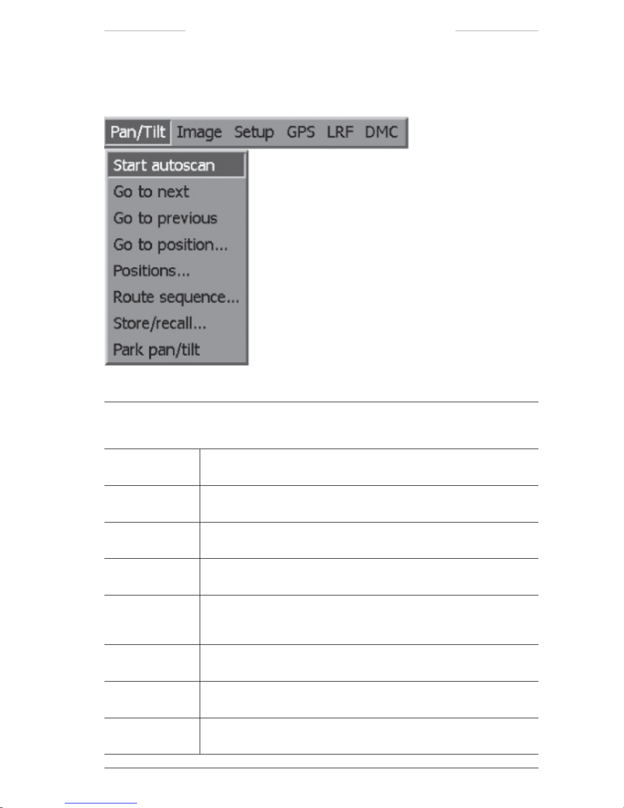
Ranger HRC™ operator´s manual – System software
Publ. No. TM 614 006 699 Rev B – ENGLISH (EN) – Oct 30. 2008 49
7.4.1 Pan/Tilt menu when IR is selected
Figure 7.5 Pan/Tilt menu when IR is selected.
Pan/Tilt menu when IR is selected
Feature Description
Start autoscan The Start autoscan feature is used to enter the system into AUTOSCAN
mode.
Go to next The Go to next feature is used to move the system as fast as possible to the
next point in the currently active scan routine.
Go to previous The Go to previous feature is used to move the system as fast as possible to
the previous point in the currently active scan routine.
Go to position… The Go to position…feature opens the Go to position dialog box, see section
7.4.1.1.
Positions… The Positions…feature opens the Current position list dialog box, see
section 7.4.1.2. If no current list exists, the New pos # dialog box is opened
instead, see section 7.4.1.2.1.
Route sequence… The Route sequence…feature opens the Route sequence dialog box, see
section 7.4.1.3.
Store/recall… The Store/recall…feature opens the Store/recall dialog box, see section
7.4.1.4.
Park pan/tilt The Park pan/tilt feature is used to send the system to the home position
and enters the system into PARK mode.
Page 60

Ranger HRC™ operator´s manual – System software
50 Publ. No. TM 614 006 699 Rev B – ENGLISH (EN) – Oct 30. 2008
7.4.1.1 Go to position
The Go to position dialog box is used to move the system to the position
of the selected autoscan point 1 to 32).
It is possible to select also autoscan points that are dened as inactive in the
Route sequence dialog box, see section 7.4.1.3. An inactive autoscan point
is still available, but it is excluded from the autoscan route sequence.)
Figure 7.6 Go to position dialog box.
Go to position dialog box
Feature Description
Number The Number feature is used to select autoscan point.
7.4.1.2 Current position list
The Current position list dialog box is used to append autoscan points to
the current autoscan list and to dene new autoscan lists.
If no current position list exists, the New pos # dialog box is opened directly,
see section 7.4.1.2.1.
Figure 7.7 Current position list dialog box.
Current position list dialog box
Feature Description
Append The Append feature is used to append new autoscan points to the current
autoscan list. The procedure for appending autoscan points is described in
section 11.4.
New The New feature is used to create a new autoscan list. The procedure for
creating autoscan lists is described in section 11.4.
NOTE: When New is selected, the current autoscan list is replaced.
To save the current list before
New is selected, see section 11.4.2.7.
Page 61

Ranger HRC™ operator´s manual – System software
Publ. No. TM 614 006 699 Rev B – ENGLISH (EN) – Oct 30. 2008 51
7.4.1.2.1 New pos #
The New pos # dialog box is used to dene the Speed and Dwell settings
of new autoscan points.
The New pos # dialog box is opened as a part of the procedures Creating
autoscan lists and Appending autoscan points, see section 11.4.2.4.
Figure 7.8 New pos # dialog box.
New pos # dialog box
Feature Description
Speed The Speed feature is used to select the rate with which the system shall
move to next autoscan point:
• Fast
• Normal
• Slow
The speed rates are set in the Setup – Pan/tilt dialog box, see section 7.6.1.3.
Dwell The Dwell feature is used to set the dwell time (in seconds); that is, how long
the system shall stay on this autoscan point before moving on to the next
point.
Page 62

Ranger HRC™ operator´s manual – System software
52 Publ. No. TM 614 006 699 Rev B – ENGLISH (EN) – Oct 30. 2008
7.4.1.2.2 Edit pos #
The Edit pos # dialog box is used to edit autoscan point settings.
The Edit pos # dialog box is opened as a part of the procedures Editing auto-
scan points settings and Moving autoscan points, see section 11.4.2.5.
Figure 7.9 Edit pos # dialog box.
Edit pos # dialog box
Feature Description
Speed The Speed feature is used to select the rate with which the system shall
move to next autoscan point:
• Fast
• Normal
• Slow
The speed rates are set in the Setup – Pan/tilt dialog box, see section 7.6.1.3.
Dwell The Dwell feature is used to set the dwell time (in seconds); that is, how
long the system shall stay on this autoscan point before moving on to the
next point.
Page 63

Ranger HRC™ operator´s manual – System software
Publ. No. TM 614 006 699 Rev B – ENGLISH (EN) – Oct 30. 2008 53
7.4.1.3 Route sequence
The Route sequence dialog box is used to dene the sequence in which the
autoscan points in the currently loaded autoscan list shall be scanned.
The Route sequence dialog box is also used to inactivate autoscan points;
that is, to exclude the point from the currently loaded autoscan list. In-
activated autoscan points are still available and can be activated again at
any time.
Figure 7.10 Route sequence dialog box.
Route sequence dialog box
Feature Description
Active The Active item displays the current sequence of the autoscan points and is
used to manage the route sequence. The procedure for managing the route
sequence is described in section 11.4.2.6.
Inactive The Inactive item displays the inactive autoscan points and is used to
activate/deactivate autoscan points. The procedure for activating/deactivating
autoscan points is described in section 11.4.2.6.
7.4.1.4 Store/recall position list
The Store/recall position list dialog box is used to store, recall and delete
autoscan lists. It is possible to store up to four different lists (A, B, C and
D), with up to 32 autoscan points in each list.
The currently loaded and active autoscan list is possible to store. Previously stored autoscan lists are possible to recall and load as the active
autoscan list. It is also possible to delete previously stored autoscan lists.
NOTE: When an autoscan list is recalled, the currently active autoscan list is overwritten.
If the operator wants to store the currently active autoscan list, it must be done before
recalling another list.
Page 64

Ranger HRC™ operator´s manual – System software
54 Publ. No. TM 614 006 699 Rev B – ENGLISH (EN) – Oct 30. 2008
Figure 7.11 Store/recall position list dialog box.
Store/recall position list dialog box
Feature Description
Action The Action feature is used to select which action to apply to the selected
List no. The procedures for storing, recalling and deleting autoscan lists are
described in section 11.4.2.7.
• Store: Stores the currently loaded autoscan list, with the list name displayed in the List no item.
• Recall: Recalls and loads the autoscan list with the list name displayed in
the List no item.
• Delete: Deletes the autoscan list with the list name displayed in the List
no item.
List no The List no feature shows the currently selected list name (A, B, C or D) and
the list status.
• Used: Indicates that there is an autoscan list stored with that name, which
can be recalled or deleted.
• Free: Indicates that this list name is free and can be used to store a new
autoscan list.
NOTE: When the autoscan list is stored, the text Saving is displayed on the monitor.
Do not shut down the system until the saving is completed.
Page 65

Ranger HRC™ operator´s manual – System software
Publ. No. TM 614 006 699 Rev B – ENGLISH (EN) – Oct 30. 2008 55
7.4.2 Pan/Tilt menu when TV is selected
Figure 7.12 Pan/Tilt menu when TV is selected.
Pan/tilt menu when TV is selected
Feature Description
Start autoscan The Start autoscan feature is used to enter the system into AUTOSCAN
mode.
Go to next The Go to next feature is used to move the system as fast as possible to the
next point in the currently active scan routine.
Go to previous The Go to previous feature is used to move the system as fast as possible to
the previous point in the currently active scan routine.
Go to position… The Go to position…feature opens the Go to position dialog box, see section
7.4.1.1.
Park pan/tilt The Park pan/tilt feature is used to send the system to the home position and
enters the system into PARK mode.
NOTE: If the Park pan/tilt feature is selected a second time when the
system is in home position, the lens cover will be closed and the
PARK mode will be entered.
Page 66
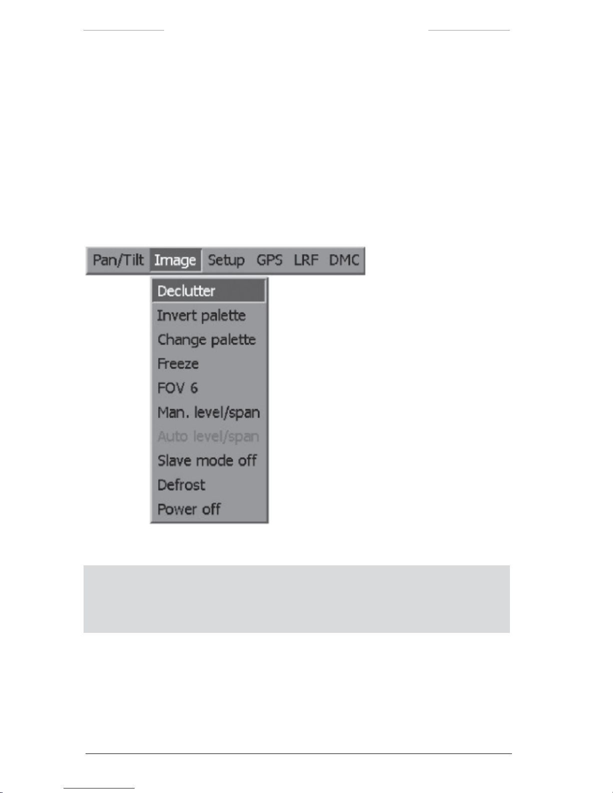
Ranger HRC™ operator´s manual – System software
56 Publ. No. TM 614 006 699 Rev B – ENGLISH (EN) – Oct 30. 2008
7.5 Image menu
The Image menu is used to manage the appearance of the image on the
monitor.
The Image menu options and features are somewhat different, depending
on if IR or TV is selected.
7.5.1 Image menu when IR is selected
Figure 7.13 Image menu when IR is selected.
NOTE: For features with on/off alternatives, the displayed feature (for example Power off)
is the action that will be performed if the feature is selected, and not the current status.
For example,
Power off means that the power is currently On and that it will be turned Off
if the feature is selected.
Page 67

Ranger HRC™ operator´s manual – System software
Publ. No. TM 614 006 699 Rev B – ENGLISH (EN) – Oct 30. 2008 57
Image menu when IR is selected
Feature Description
Declutter The Declutter feature is used to temporarily remove the system information
from the monitor. When the ENTER button is pressed, the system information is shown again.
Invert palette The Invert palette feature is used to invert the current IR palette:
• Gray (white hot) to Inv Gray (black hot) or vice versa.
• Rainbow to Inv Rainbow or vice versa.
• Rainbow HC to Inv Rainbow HC or vice versa.
• Iron to Inv Iron or vice versa.
NOTE: The IR palette can also be inverted in the Setup menu, see
section 7.6.1.1.
Change palette The Change palette feature is used to cycle trough the IR palette options:
• Gray
• Rainbow
• Rainbow HC
• Iron
NOTE: The IR palette can also be changed in the Setup menu, see
section 7.6.1.1.
Freeze/Live The Freeze/Live feature is used to change the monitor from live to frozen
image or vice versa. When the image is frozen, the text Frozen is displayed
on the monitor.
FOV The FOV feature is used to move the system to the next preset eld-of-view
(FOV).
NOTE: The available preset elds-of-view depend on the type of IR
camera. The preset elds-of-view are the same for the IR and TV
cameras.
Man. level/span The Man. level/span feature opens the Man. level/span dialog box, see
section 7.5.1.
Auto level/span The Auto level/span feature is used to enter the automatic adjustment mode
(Auto (linear) or Auto (full)), as set in the Setup – Image dialog box, see
section 7.5.1.
The
Auto level/span feature is only enabled when the system is in Man.
level/span mode.
Page 68

Ranger HRC™ operator´s manual – System software
58 Publ. No. TM 614 006 699 Rev B – ENGLISH (EN) – Oct 30. 2008
Slave mode on/off The Slave mode on/off feature is used to activate/deactivate Slave mode.
When
Slave mode is active, changes in eld-of-view will apply to both the IR
and TV camera.
Defrost The Defrost feature is used to activate the lens defroster. When Defrost is
selected, the lens defroster is turned on for 10 minutes. The defroster is
automatically turned off after 10 minutes or when the joystick is moved.
The
Defrost feature is only enabled at freezing ambient temperature.
Power on/off The Power on/off feature is used to turn on/off the IR camera.
When the IR camera is turned off, a colored image is displayed on the moni
-
tor and all features in the Image menu, except Power on, are disabled.
7.5.1.1 Man. level/span
The Man. level/span dialog box is used to manually adjust the level and
span settings.
Figure 7.14 Man. level/span dialog box.
NOTE: The system will remain in MANUAL mode until the feature Auto level/span is
selected.
Man. level/span dialog box
Feature Description
Level The Level feature is used to adjust the level setting.
Span The Span feature is used to adjust the span setting.
Page 69
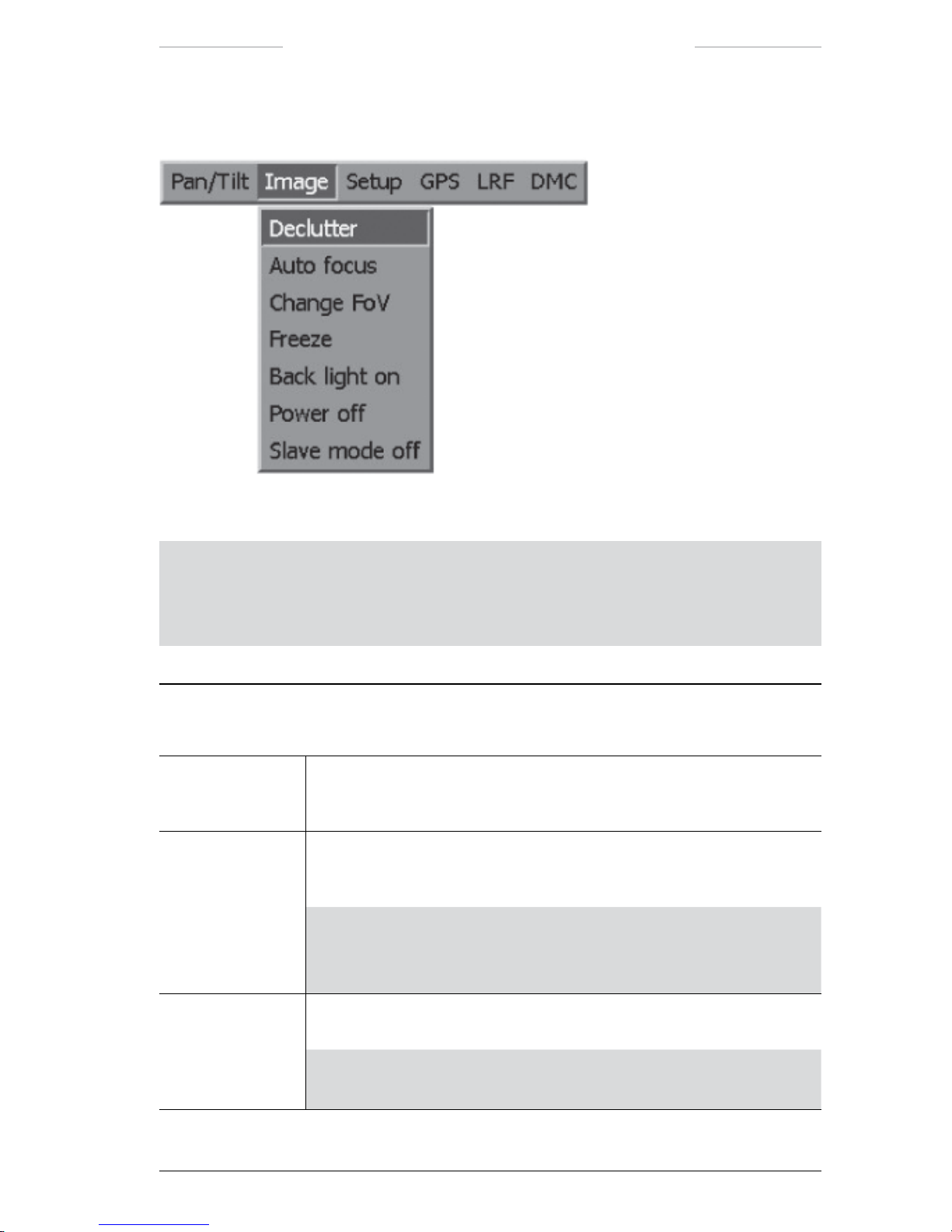
Ranger HRC™ operator´s manual – System software
Publ. No. TM 614 006 699 Rev B – ENGLISH (EN) – Oct 30. 2008 59
7.5.2 Image menu when TV is selected
Figure 7.15 Image menu when TV is selected.
NOTE: For features with on/off alternatives, the displayed feature (for example Power off)
is the action that will be performed if the feature is selected, and not the current status.
For example,
Power off means that the power is currently On and that it will be turned Off
if the feature is selected.
Image menu when TV is selected
Feature Description
Declutter The Declutter feature is used to temporarily remove the system information
from the monitor. When the ENTER button is pressed, the system informa
-
tion is shown again.
Auto focus The Auto focus feature is used to execute a one-shot auto focus adjustment.
(Continuous auto focus is not provided, because of the risk for mechanical
wear.)
NOTE: The Auto focus feature is not supported by all TV cameras.
If not supported, the
Auto focus feature is disabled in the Image
menu.
Change FoV The Change FoV feature is used to move the system to the next preset eld-
of-view (FOV).
NOTE: The available preset elds-of-view for the TV camera are the
same as for the IR camera (if supported by the TV camera).
Page 70
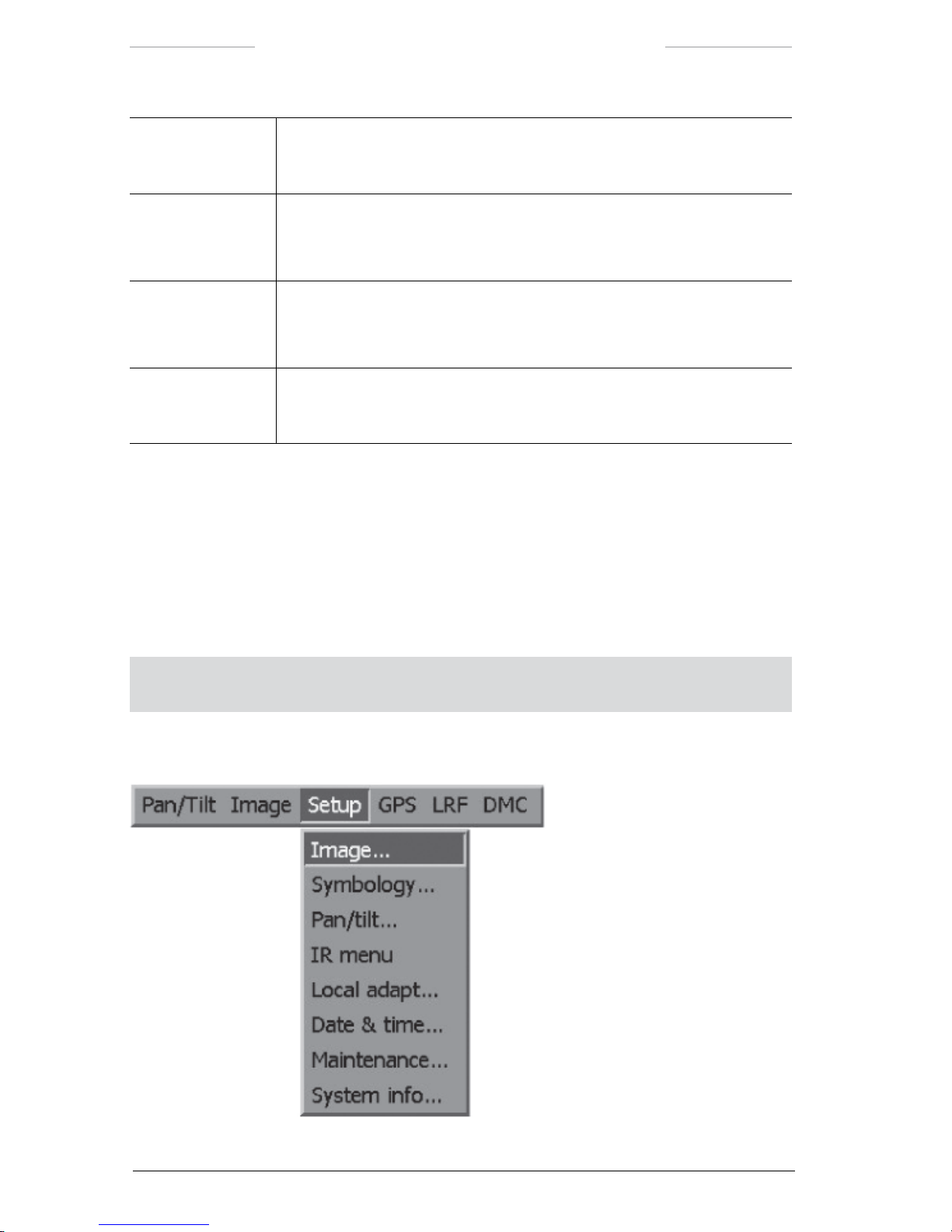
Ranger HRC™ operator´s manual – System software
60 Publ. No. TM 614 006 699 Rev B – ENGLISH (EN) – Oct 30. 2008
Freeze/Live The Freeze/Live feature is used to change the monitor from live to frozen
image or vice versa. When the image is frozen, the text Frozen is displayed
on the monitor.
Back light on/off The Back light on/off feature turns on/off the backlight compensation.
If an object appears in front of a very light background – or if the object is
very dark – the backlight will increase the image quality.
Power on/off The Power on/off feature is used to turn on/off the TV camera.
When the TV camera is turned off, a colored image is displayed on the
monitor and all features in the
Image menu, except Power on, are disabled.
Slave mode on/off The Slave mode on/off feature is used to activate/deactivate Slave mode.
When Slave mode is active, changes in eld-of-view will apply to both the IR
and TV camera.
7.6 Setup menu
The Setup menu is used to dene system constants and the appearance
of the system information indicators.
The Setup menu options and features are somewhat different, depending
on if IR or TV is selected.
NOTE: Settings made in the Setup menu will apply until the system is turned off. How-
ever, the settings are permanently saved when the
PRK button on the JCU is pressed.
7.6.1 Setup menu when IR is selected
Figure 7.16 Setup menu when IR is selected.
Page 71

Ranger HRC™ operator´s manual – System software
Publ. No. TM 614 006 699 Rev B – ENGLISH (EN) – Oct 30. 2008 61
Setup menu when IR is selected
Feature Description
Image…
The Image…feature opens the Setup – Image dialog box, see section 7.6.1.1.
Symbology… The Symbology…feature opens the Setup – Symbology dialog box, see
section 7.6.1.2.
Pan/tilt…
The Pan/tilt…feature opens the Setup – Pan/tilt dialog box, see section 7.6.1.3.
IR menu The IR menu feature is used to open the menu system of the IR Camera, see
chapter 8.
To exit the IR Camera menu system, press the CANCEL button. If not in use
for a while, the IR Camera menu system is automatically exited.
Local adapt… The Local adapt…feature opens the Setup – Local adapt dialog box, see
section 7.6.1.4.
Date & time… The Date & time…feature opens the Setup – Date & time dialog box, see
section 7.6.1.5.
Maintenance… The Maintenance…feature opens the Setup – Maintenance dialog box, see
section 7.6.1.6.
System info… The System info…feature opens the System information dialog box, see
section 7.6.1.7.
7.6.1.1 Setup – Image
The Setup – Image dialog box is used control the appearance of the IR
image.
Figure 7.17 Setup – Image dialog box when IR is selected.
Page 72

Ranger HRC™ operator´s manual – System software
62 Publ. No. TM 614 006 699 Rev B – ENGLISH (EN) – Oct 30. 2008
Setup – Image dialog box
Feature Description
Color scale The Color scale feature is used to select IR palette:
• Gray
• Gray inv (inverted)
• Rainbow
• Rainbow inv (inverted)
• Iron
• Iron inv (inverted)
• Rainbow HC
• Rainbow HC inv (inverted)
Level/Span The Level/Span feature is used to select adjustment mode.
• Manual: Manual adjustment of level and span.
• Auto (linear): Automatic adjustment of level and span, with Color
Distribution in Linear mode.
• Auto (full): Automatic adjustment of level and span, with Color
Distribution in Histogram mode.
• DDE (linear): Automatic adjustment of level and span, with Digital Detail
Enhancement and Color Distribution in Linear mode.
• DDE (full): Automatic adjustment of level and span, with Digital Detail
Enhancement and Color Distribution in Histogram mode.
Nuc button The Nuc button feature is used to change the operational mode of the NUC
button on the JCU.
• NUC/AF (this is the default setting):
Press button NUC < 1 second to perform an Internal NUC
Press button NUC > 1 second, to perform a on-shot auto focus adjustment
and
Press buttons FCN + NUC < 1 second to perform an External NUC.
Press buttons FCN + NUC > 1 second to go to the xed focus position.
and
Press the C + NUC buttons < 1 second to perform an External NUC
against the scene.
Press the C + NUC buttons > 1 second to perform a one-shot auto focus
adjustment.
Page 73

Ranger HRC™ operator´s manual – System software
Publ. No. TM 614 006 699 Rev B – ENGLISH (EN) – Oct 30. 2008 63
Setup – Image dialog box
Feature Description
Nuc button • AF/NUC:
Press button NUC < 1 second to perform a on-shot auto focus adjustment
Press button NUC > 1 second, to perform an Internal NUC
and
Press buttons FCN + NUC < 1 second to go to the xed focus position.
Press buttons FCN + NUC > 1 second to perform an External NUC.
and
Press the
C + NUC buttons < 1 second to perform a one-shot auto focus
adjustment.
Press the
C + NUC buttons > 1 second to perform an External NUC
against the scene.
Adjust DDE The Adjust DDE feature is used to adjust the DDE Control value.
• Yes: Opens the DDE dialog box, see section 7.6.1.1.1.
• No: No action.
Preset focus
distance
The Preset focus distance feature is used to set the xed focus distance.
If auto focus is not possible, for example when the image has low contrasts
between different areas, the system will focus to the xed focus distance
instead.
7.6.1.1.1 DDE dialog box
The DDE dialog box is used to adjust the DDE Control value.
Figure 7.18 DDE dialog box.
For more information about DDE Control, see section 5.2.6 DDE – Digital
Detail Enhancement.
Page 74

Ranger HRC™ operator´s manual – System software
64 Publ. No. TM 614 006 699 Rev B – ENGLISH (EN) – Oct 30. 2008
7.6.1.2 Setup –Symbology
The Setup – Symbology dialog box is used to dene how the overlaid
symbology (system information indicators) is displayed on the monitor.
The Setup – Symbology dialog box is the same for IR and TV, except for
the FOV brackets and Scan points features which are not available when
TV is selected.
Figure 7.19 Setup – Symbology dialog box when IR is selected.
Setup – Symbology dialog box
Feature Description
Data eld The Data eld feature is used to control the appearance of the two lines of
system information that is presented at the bottom of the monitor.
• Normal: Both lines of information are shown.
• Reduced: Only the bottom line of information is shown; that is, date, time
and digital azimuth and elevation.
• None: Both lines are hidden.
Data background The Data background feature is used to control the appearance of the
background of the two lines of system information that is presented at the
bottom of the monitor.
• Solid: Puts a solid background behind the two lines of information, which
makes them more visible.
• Transparent: No background behind the two lines of information.
Page 75

Ranger HRC™ operator´s manual – System software
Publ. No. TM 614 006 699 Rev B – ENGLISH (EN) – Oct 30. 2008 65
Setup – Symbology dialog box
Feature Description
Status background The Status background feature is used to control the appearance of the
background of the status text, which is displayed in the upper left corner
when the functions they represent are trigged.
• Solid: Puts a solid background behind the additional system information,
which makes them more visible.
• Transparent: No background behind the additional system information.
Pos indicator The Pos indicator feature is used to control the appearance of the analog
azimuth and elevation indicators.
• On: The analog azimuth and elevation indicators are always shown.
• Off: The analog azimuth and elevation indicators are always hidden.
• When changed: The analog azimuth and elevation indicators are only
shown when the position of the system is changed.
Focus indicator The Focus indicator feature is used to control the appearance of the focus
position indicator.
• On: The focus position indicator is always shown.
• Off: The focus position indicator is always hidden.
• When changed: The focus position indicator is only shown when the
focus is changed.
Crosshair retic The Crosshair retic feature is used to control the appearance of the crosshair
reticle indicator.
• On: The crosshair reticle indicator is shown.
• Off: The crosshair reticle indicator is hidden.
FOV brackets The FOV brackets feature is used to control the appearance of the FOV
brackets indicator.
• On: The FOV brackets indicator is shown. (When the next FOV is the
widest FOV, no
FOV brackets are shown.)
• Off: The FOV brackets indicator is hidden.
Scan points The Scan points feature is used to control the appearance of the Autoscan
point number indicator.
• Digits on: The autoscan point number (digit) and the targeting square are
shown.
• On: Only the targeting square is shown.
• Off: No autoscan point information is shown.
Adjust GUI size The Adjust GUI size feature is used to adjust the size of the area where
the system software graphics (system information and menu system) is
displayed on the monitor.
• Yes: Opens the Setup – GUI size dialog box, see section 7.6.1.2.1.
• No: No action.
Page 76

Ranger HRC™ operator´s manual – System software
66 Publ. No. TM 614 006 699 Rev B – ENGLISH (EN) – Oct 30. 2008
7.6.1.2.1 Setup – GUI Size dialog box
The Setup – GUI size dialog box is used to select GUI size.
The crosshair reticle, the FOV brackets and the autoscan point indicators
are not affected by the change of GUI size.
Figure 7.20 Setup – GUI size dialog box.
Setup – GUI Size dialog box
Feature Description
Preset mode The Preset mode feature is used to select GUI size mode.
• Full: The full area is used to display the system software graphics. This
setting keeps as much as possible of the video image free from overlaid
information. However, many monitors cut the video image close to the
edges. With such a monitor, some of the graphics may not be visible with
this setting.
• Compressed: The edges of the area where the system software graphics
is displayed are adjusted to allow all graphics to be visible. This is a xed
setting that ts most monitors.
• Custom: Enables manual settings of Left, Top, Right and Bottom edges.
Left/Top/Right/
Bottom edge
The Left/Top/Right/Bottom edge items are used to adjust the edges of the
area where the system software graphics is displayed. The edges can only
be adjusted when Custom is selected.
Page 77

Ranger HRC™ operator´s manual – System software
Publ. No. TM 614 006 699 Rev B – ENGLISH (EN) – Oct 30. 2008 67
7.6.1.3 Setup – Pan/tilt
The Setup – Pan/tilt dialog box is used to dene settings and control func-
tions of the Pan/Tilt unit.
The Setup – Pan/tilt dialog box is the same for IR and TV.
Figure 7.21 Setup – Pan/tilt dialog box.
Setup – Pan/tilt dialog box
Feature Description
Autoscan speeds The Autoscan speeds feature is used to dene the preset autoscan speed
rates; Slow, Normal and Fast. The autoscan speed is the speed with which
the system moves to the next autoscan point.
The
Slow, Normal and Fast values are adjustable from 0,1˚/s to 70˚/s (pan)
and from 0.1˚/s to 30˚/s (tilt), both in 0.1˚/s increments.
The values must follow a logical progression; that is, it is not possible to
adjust the normal setting to a value that is less than the slow setting.
The same value is used for pan and tilt, up to the maximum value for tilt
(30˚/s). If the value is set higher than that, the tilt value will be kept to its
maximum.
Azimuth The Azimuth feature is used to dene the home position, see section 10.3.
The
Azimuth value is adjustable from 0.0˚/s to 359.9˚/s, in 0.1˚/s increments.
Page 78

Ranger HRC™ operator´s manual – System software
68 Publ. No. TM 614 006 699 Rev B – ENGLISH (EN) – Oct 30. 2008
Setup – Pan/tilt dialog box
Feature Description
Joystick polarity The Joystick polarity feature is used to select the operational mode of the
joystick.
• Normal: When the operator moves the joystick towards himself, the
Pan/Tilt unit will move downwards.
• Pilot: When the operator moves the joystick away from himself, the
Pan/Tilt unit will move downwards.
P/T-Speed relative
zoom
The P/T-Speed relative zoom feature is used to control the speed of the
Pan/Tilt unit in relation to the current eld-of-view.
• On: The panning and tilting speeds are lower for narrower elds-of-view.
• Off: The panning and tilting speeds are the same for all elds-of-view.
Left/Right scanpoint selection
The Left/Right scanpoint selection feature is used to control the function of
the and buttons on the JCU.
• On: The and buttons are used to move the system to the previous/next autoscan point. This is the default setting.
• Off: The and buttons can not be used to move the system to the
previous/next autoscan point.
Page 79

Ranger HRC™ operator´s manual – System software
Publ. No. TM 614 006 699 Rev B – ENGLISH (EN) – Oct 30. 2008 69
7.6.1.4 Setup – Local adapt
The Setup – Local adapt dialog box is used to select language and the
date and time formats.
The Setup – Local adapt dialog box is the same for IR and TV.
Figure 7.22 Setup – Local adapt dialog box.
Setup – Local adapt dialog box
Feature Description
Language The Language feature is used to select the system language. English is the
default language.
Date format The Date format feature is used to select the date format:
• DD/MM/YY
• YY-MM-DD
• MM/DD/YY
Time format The Time format feature is used to select the time format:
• HH:MM:SS (24 hour format)
• HH.MM.SS (24 hour format)
• HH:MM:SS PM (12 hour format)
Page 80

Ranger HRC™ operator´s manual – System software
70 Publ. No. TM 614 006 699 Rev B – ENGLISH (EN) – Oct 30. 2008
7.6.1.5 Setup – Date & time
The Setup – Date & time dialog box is used to set the system date and
time.
The Setup – Date & time dialog box is the same for IR and TV.
Figure 7.23 Setup – Date & time dialog box.
Setup – Date & time dialog box
Feature Description
Year The Year feature is used to set the year:
• 2003-2038
Month The Month feature is use to set the month:
• 01-12
Day The Day feature is use to set the day:
• 01-31
Hour The Hour feature is used to set the hour. The Hour format depends on the
settings made in the Setup – Local Adapt dialog box, see section 7.6.1.4.
• 12 hour format:
12 AM-12 PM
• 24 hour format:
01-24
Minute The Minute feature is used to set the minute:
• 00-59
NOTE: The seconds are set to 00 when the ENTER button is pressed to conrm the
settings in the
Setup – Date & time dialog box.
Page 81
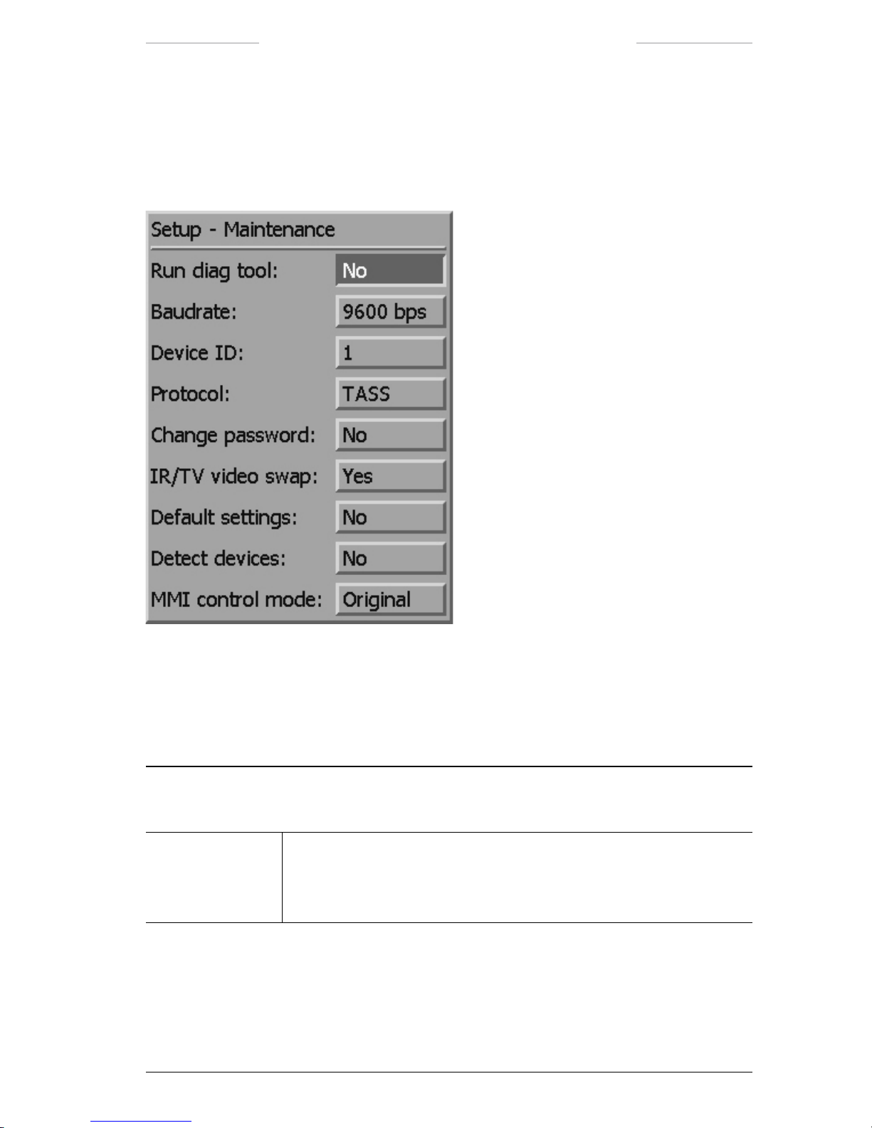
Ranger HRC™ operator´s manual – System software
Publ. No. TM 614 006 699 Rev B – ENGLISH (EN) – Oct 30. 2008 71
7.6.1.6 Setup – Maintenance
The Setup – Maintenance dialog box is used to dene system constants.
The Setup – Maintenance dialog box is the same for IR and TV.
Figure 7.24 Setup – Maintenance dialog box.
If a password other than the default system value 0000 has been set, the
Enter password dialog box will appear before the Setup – Maintenance
dialog box is opened. See section 7.6.1.6.1.
Setup – Maintenance dialog box
Feature Description
Run diag tool The Run diag tool feature is used to start the diagnostic test.
• Yes: Opens the Setup – Diag tool dialog box, see section 15.7.
• No: No action.
Page 82

Ranger HRC™ operator´s manual – System software
72 Publ. No. TM 614 006 699 Rev B – ENGLISH (EN) – Oct 30. 2008
Setup – Maintenance dialog box
Feature Description
Baudrate The Baudrate feature is used to set the communication speed.
• 1200 bps
• 2400 bps
• 4800 bps
• 9600 bps
• 19200 bps
The new Baudrate value will take effect immediately.
NOTE: If the Baudrate is changed, it will take a few button presses or
joystick movements before the JCU is in sync again.
Device ID The Device ID feature is used to set the device ID:
• 01-31
NOTE: If the 5x0 protocol (see the Protocol feature below) is selected,
the Device ID feature is disabled.
Protocol The Protocol feature is used to select the type of communication protocol:
• 5x0
• TASS
• Optional protocols, such as PELCO D, are available on request.
The new protocol setting will take effect immediately.
NOTE: If the protocol is changed, it will take a few button presses or
joystick movements before the JCU is in sync again.
NOTE: As 5x0 is a point-to-point protocol, no Device ID can be
selected.
Change password The Change password feature is used to enter a password or change the
existing password for the Setup – Maintenance dialog box.
• Yes: Opens the New password or Change password dialog box, see
section 7.6.1.6.2 and 7.6.1.6.3.
• No: No action.
Page 83

Ranger HRC™ operator´s manual – System software
Publ. No. TM 614 006 699 Rev B – ENGLISH (EN) – Oct 30. 2008 73
Setup – Maintenance dialog box
Feature Description
IR/TV video swap The IR/TV video swap feature is used to control the video signal.
• Yes: The active video signal is swapped between the two video outputs
on the JPC2 when the operator toggles between IR and TV. If two monitors are used, the TV and IR images will move between the monitors.
• No: Only the indicator for active channel will move between the monitors.
Default settings The Default setting feature is used to reset parameters, except for example
lists of autoscan points, Baudrate and Protocol, to factory settings.
• Yes: The default settings are reset.
• No: No action.
Detect devices The Detect devices feature is used to check for system changes and make
required adjustments.
• Yes: Opens the Detect devices dialog box, see section 7.6.1.6.4.
• No: No action.
MMI Control mode The Joystick Control Unit (JCU) operates with two different settings, with
somewhat different functions for the joystick and the keypad buttons, see
section 6.2.1.
The
MMI Control mode feature is used to select the JCU setting.
• Original
• Alternative
NOTE: Another commonly used term corresponding to MMI (Man
Machine Interface) is GUI (Graphical User Interface).
Page 84

Ranger HRC™ operator´s manual – System software
74 Publ. No. TM 614 006 699 Rev B – ENGLISH (EN) – Oct 30. 2008
7.6.1.6.1 Enter password
The Enter password dialog box appears before the Setup – Maintenance
dialog box is opened, if a password other than the default system value
0000 has been set.
Figure 7.25 Enter password dialog box.
Enter password dialog box
Feature Description
Enter password The Enter password feature is used to enter the password.
If the CANCEL button is pressed, the Setup – Maintenance dialog box
will be displayed with most features disabled.
Figure 7.26 Setup – Maintenance dialog box with disabled features.
Page 85

Ranger HRC™ operator´s manual – System software
Publ. No. TM 614 006 699 Rev B – ENGLISH (EN) – Oct 30. 2008 75
7.6.1.6.2 New password
The New password dialog box is used to set a password.
Figure 5.27 New password dialog box.
7.6.1.6.3 Change password
The Change password dialog box is used to change an existing pass-
word.
Figure 7.28 Change password.
7.6.1.6.4 Detect devices
The Detect devices dialog box is used to start a check for system changes.
If a change is found, the system will automatically make necessary
adjustments.
Figure 7.29 Detect devices dialog box.
Page 86
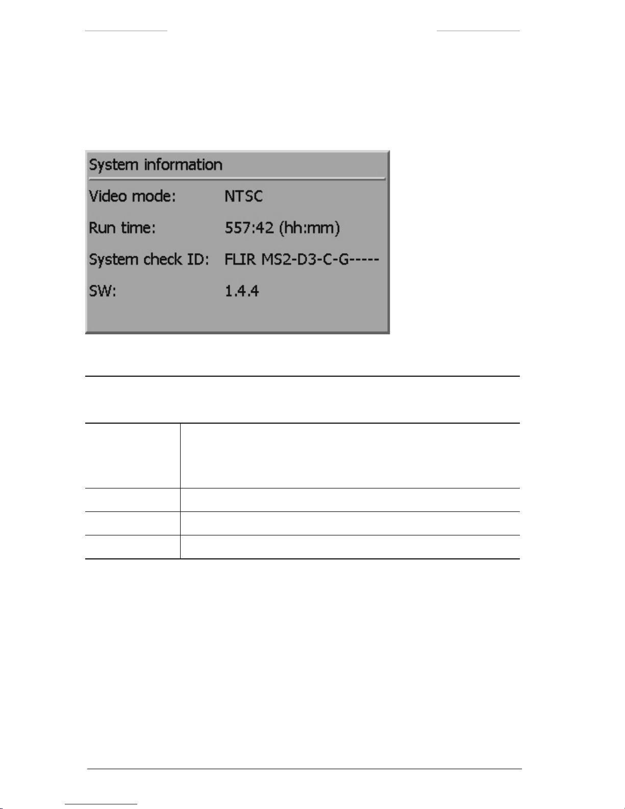
Ranger HRC™ operator´s manual – System software
76 Publ. No. TM 614 006 699 Rev B – ENGLISH (EN) – Oct 30. 2008
7.6.1.7 System information
The System information dialog box displays information about the system.
The System information dialog box is the same for IR and TV.
Figure 7.30 System information dialog box.
System information dialog box
Feature Description
Video mode The Video mode item displays the type of video mode in use:
• NTSC
• PAL
Run time The Run time item displays the run time of the IR Camera.
System check ID The System check ID item displays the conguration code.
SW The SW item displays the current software version.
Page 87

Ranger HRC™ operator´s manual – System software
Publ. No. TM 614 006 699 Rev B – ENGLISH (EN) – Oct 30. 2008 77
7.6.2 Setup menu when TV is selected
Figure 7.31 Setup menu when TV is selected.
Setup menu when TV is selected
Feature Description
Image… The Image…feature opens the Setup – Image dialog box, see section
7.6.2.1.
Symbology… The Symbology…feature opens the Setup – Symbology dialog box, see
section 7.6.2.2.
Pan/tilt… The Pan/tilt…feature opens the Setup – Pan/tilt dialog box, see section
7.6.1.3.
Local adapt… The Local adapt…feature opens the Setup – Local adapt dialog box, see
section 7.6.1.4.
Date & time… The Date & time…feature opens the Setup – Date & time dialog box, see
section 7.6.1.5.
Maintenance… The Maintenance…feature opens the Setup – Maintenance dialog box, see
section 7.6.1.6.
System info… The System info…feature opens the System information dialog box, see
section 7.6.1.7.
Page 88

Ranger HRC™ operator´s manual – System software
78 Publ. No. TM 614 006 699 Rev B – ENGLISH (EN) – Oct 30. 2008
7.6.2.1 Setup – Image
The Setup – Image dialog box is used to control the appearance of the TV
image.
NOTE: The features in the Setup – Dialog box are not supported by all TV cameras.
Figure 7.32 Setup – Image dialog box when TV is selected.
Setup – Image dialog box
Feature Description
Back light comp The Back light comp feature is used to turn on/off the backlight.
• Off: Turns off the backlight.
• On: Turns on the backlight compensation. If an object appears in front of
a very light background – or if the object is very dark – the backlight will
increase the image quality.
Image effect The Image effect feature is used to select Color or Black/White mode.
• Off: Puts the TV camera in Color mode.
• B/W: Puts the TV camera in Black/White mode.
Near IR sensitive The Near IR sensitive feature is used to increase the sensitivity to IR radia-
tion by disabling a built-in cut-off IR radiation lter. The feature is especially
valuable under twilight conditions.
• Off: Deactivates the Near IR sensitive feature.
• On: Activates the Near IR sensitive feature.
7.6.2.2 Setup – Symbology
The features of the Setup – Symbology dialog box when TV is selected are
the same as when IR is selected, see section 7.6.1.2, but the FOV brackets
and Autoscan point number indicators are not visible when TV is selected.
Page 89
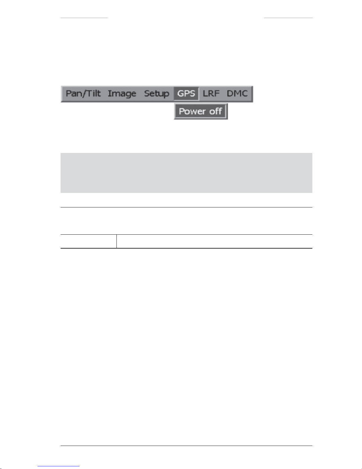
Ranger HRC™ operator´s manual – System software
Publ. No. TM 614 006 699 Rev B – ENGLISH (EN) – Oct 30. 2008 79
7.7 GPS menu
The GPS menu is used to control the GPS (Global Positioning System)
unit.
Figure 7.33 GPS menu.
NOTE: For features with on/off alternatives, the displayed feature (for example Power off)
is the action that will be performed if the feature is selected, and not the current status.
For example,
Power off means that the power is currently On and that it will be turned Off
if the feature is selected.
GPS menu
Feature Description
Power on/off The Power on/off feature is used to turn the GPS unit on/off.
Page 90
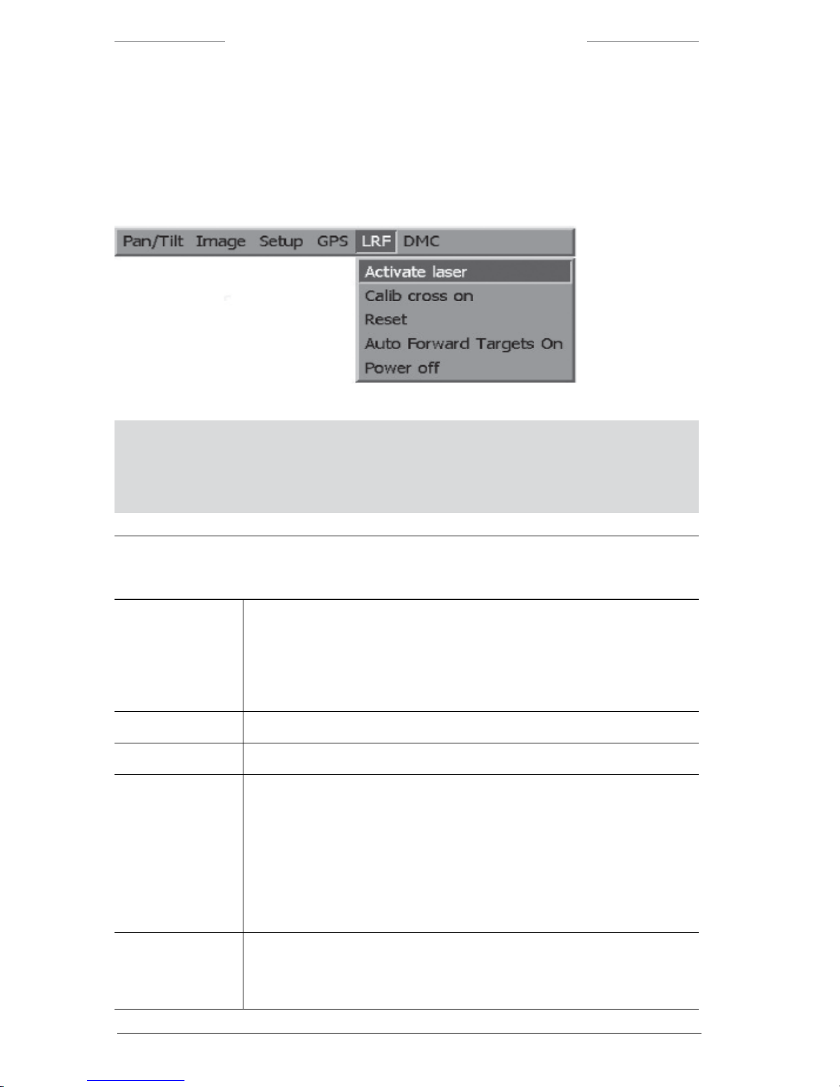
Ranger HRC™ operator´s manual – System software
80 Publ. No. TM 614 006 699 Rev B – ENGLISH (EN) – Oct 30. 2008
7.8 LRF menu
The LRF menu is used to control the LRF (Laser Range Finder) unit.
The procedures for measuring distances with the LRF unit is described
in section 11.5.
Figure 7.34 LRF menu.
NOTE: For features with on/off alternatives, the displayed feature (for example Power off)
is the action that will be performed if the feature is selected, and not the current status.
For example,
Power off means that the power is currently On and that it will be turned Off
if the feature is selected.
LRF menu
Feature Description
Activate laser The Activate laser feature is used to activate the LRF unit and to enter the
system into LRF mode. When the unit has been activated, the text “Laser
ready (6)” is displayed in the upper left corner of the monitor. In LRF mode,
most buttons are disabled.
Press button
C to deactivate the LRF unit and to exit the LRF mode.
Calib cross On/Off The Calib cross feature is used calibration.
Reset The Reset feature is used to reset the LRF unit.
Auto Forward
Targets On/Off
When the system is used with a remote computer, the distance results can
be reported to the remote computer. The Auto Forward Targets feature is
used to select which results to report; all valid result or approved results.
(The operator approves a result by pressing the ENTER button for each
result he wants to have reported, see section 11.5.2.)
• Auto Forward Targets On: All valid results are reported.
• Auto Forward Targets Off: Only approved results are reported.
Power on/off The Power on/off feature is used to turn the LRF unit on/off.
When the LRF unit is turned off, all menu items in the LRF menu, except
Power on, are disabled.
Page 91
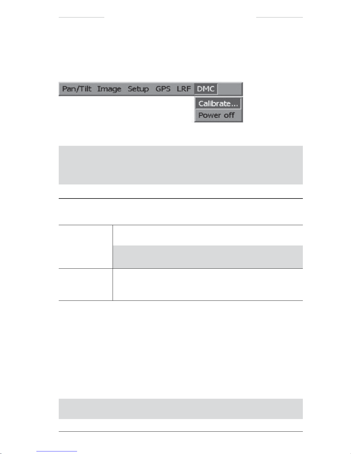
Ranger HRC™ operator´s manual – System software
Publ. No. TM 614 006 699 Rev B – ENGLISH (EN) – Oct 30. 2008 81
7.9 DMC menu
The DMC menu is used to control the DMC (Digital Magnetic Compass)
unit.
Figure 7.35 DMC menu.
NOTE: For features with on/off alternatives, the displayed feature (for example Power off)
is the action that will be performed if the feature is selected, and not the current status.
For example,
Power off means that the power is currently On and that it will be turned Off
if the feature is selected.
LRF menu
Feature Description
Calibrate… The Calibrate feature opens the DMC Calibration mode dialog box, see
section 7.9.1.
NOTE: The Calibrate feature is disabled until the Pan/Tilt unit is
activated, which is done when the
PRK button is pressed >3 seconds.
Power on/off The Power on/off feature is used to turn the DMC unit on/off.
When the DMC unit is turned off, all menu items in the DMC menu, except
Power on, are disabled.
7.9.1 DMC Calibration mode
The DMC Calibration mode dialog box is used to calibrate the DMC unit,
in order to nd true north. The DMC unit nds the magnetic north, which
can be corrected to obtain true north. See section 10.3.)
Calibration of the DMC unit is typically done once per installation. That
is, if the system is not moved, no new calibration is needed. The DMC
Calibration procedure is described in section 10.3.1.
NOTE: The Azimuth value in the Setup – Pan/Tilt dialog box will automatically be
adjusted to correspond with the magnetic north reading of the DMC unit.
Page 92

Ranger HRC™ operator´s manual – System software
82 Publ. No. TM 614 006 699 Rev B – ENGLISH (EN) – Oct 30. 2008
NOTE: The IR Camera shall be turned off before the DMC calibration starts, since it may
interfere with the magnetic measurements.
Figure 7.36 DMC Calibration mode dialog box.
DMC Calibration mode dialog box
Feature Description
Magnetic north
reading
The Magnetic north reading item displays the magnetic north reading reported by the DMC unit.
True north
correction
The True north correction feature is used to enter a known deviation
between magnetic north and true north. A negative number corrects towards
west and a positive number towards east.
NOTE: The True north correction value has to be entered before the
calibration is started.
Calibration score The Calibration score indicates the quality of the measurement. A poor
score is an indication of magnetic interference, for example iron, vehicles,
transformers or power lines.
• Horizontal: Shall ideally be 9, on a scale from 0 to 9.
• Vertical: Shall ideally be 9, on a scale from 0 to 9.
• Mag. of local eld: Shall be low, on a scale from 0 to 100.
Page 93

Publ. No. TM 614 006 699 Rev B – ENGLISH (EN) – Oct 30. 2008 83
8
IR Camera software
The IR Camera software is used to control the IR Camera directly. The
IR Camera menu system gives access to all the functions that are used to
control the IR image quality. The software also provides the operator with
information about the IR Camera.
For most operators, the features for control of the IR image that are avail-
able via the System Software menu system and the Joystick Control Unit
JCU) are fully sufcient, see section 11.3.
8.1 IR Camera information
Information from the IR Camera can be displayed on top of the IR image
on the monitor. In the GUI Setup dialog box it is possible to select which
information to display on the monitor, see section 8.3.3.2.
NOTE: When the IR Camera menu system is not opened, the IR Camera information
in the bottom line is hidden behind the system information displayed by the System
Software.
Figure 8.1 IR Camera information.
Page 94

Ranger HRC™ operator´s manual – IR Camera software
84 Publ. No. TM 614 006 699 Rev B – ENGLISH (EN) – Oct 30. 2008
IR Camera information
Callout Description
1 Top line status indicator: OFF, LO or HI (current noise lter)
2 Top line status indicator: FOV xx.x (current eld of view angle)
3 Top line status indicator: X2, X4 or X1 (zoom indicator; ‘X1’ will not be displayed)
4 Top line status indicator:
• AUTO = automatic adjustment mode
• AUTO* = contrast (span) and/or brightness (level) adjusted with an offset of ± 50 %
• AUTO L = automatic level adjustment mode
• AUTO L* = brightness (level) adjusted with an offset of ± 50 %
• MANUAL = manual adjustment mode
• FREEZE = image freezed mode
• RECALL = image recalled mode
5 Top line status indicator: HIST, LIN (histogram or linear color distribution mode)
6
Top line status indicator: WHITE or BLACK (polarity selection, i.e. white = hot or
black = hot)
7 Focus position indicator. Indicates the present focus position. Focusing against innity
result in indicator arrow moving towards the right side.
8 Alert indicator. The indicator is displayed when some kind of system failure has occur-
red. The camera is operating with reduced functionality.
9 Defroster indicator. The indicator is displayed when the defroster (frontlens heater) is
active.
10 Dynamic range indicator. The dynamic range indicator shows the dynamic range of the
current image in relation to the calibrated range. The position of the bar indicates the
level, while the width of the bar indicates the span.
11 Calibration crosshair. User adjustable crosshair.
12 Center position crosshair. Indicates the center of the optical axis.
13 Bottom line status indicator: Present date and time
14 Range
15 Logo type on
Page 95

Ranger HRC™ operator´s manual – IR Camera software
Publ. No. TM 614 006 699 Rev B – ENGLISH (EN) – Oct 30. 2008 85
8.2 IR Camera menu system
The IR Camera menu system gives access to the features of the IR Camera. The IR Camera menu system is opened from the System Software,
with the IR menu feature in the Setup menu. When the IR menu feature
is selected, a menu bar with the currently selected IR Camera menu and
feature highlighted is displayed.
Features that directly perform an action are displayed as a command, for
example NUC. Features that open up a dialog box are displayed with three
dots after the feature title, for example Zoom…. Features that currently
are disabled and not available for selection are shaded in the menu.
The Joystick Control Unit JCU) is used to navigate in the IR Camera
menu system and to execute actions, see chapter 6.
The CANCEL button is used to exit the IR Camera menu system. If not in
use for a while, the IR Camera menu system is automatically exited.
Page 96

Ranger HRC™ operator´s manual – IR Camera software
86 Publ. No. TM 614 006 699 Rev B – ENGLISH (EN) – Oct 30. 2008
8.3 Main menu bar
Figure 8.1 Main menu bar.
NOTE: Setup and Tools have no arrow, which means that you can not access these submenus without entering an access code.
8.3.1 Image menu
Figure 8.2 Image menu.
Menu choice Possible choices Explanation
Zoom in
Zoom out
– The camera has four xed zoom positions.
Press the ENTER button on Zoom in or Zoom
out, to select the nearest xed zoom position.
NOTE: If the camera is already in its most
zoomed in or zoomed out position then
the corresponding menu selection will be
disabled.
Page 97

Ranger HRC™ operator´s manual – IR Camera software
Publ. No. TM 614 006 699 Rev B – ENGLISH (EN) – Oct 30. 2008 87
Menu choice Possible choices Explanation
Zoom… – Press the ENTER button to display the Zoom
dialog box.
• To change the zoom position, select the
top button and then press the navigation
pad left/right.
• To change the zoom speed (0-100) select
Speed and use the navigation pad to
adjust the speed value.
Select the
Digital Zoom button and press the
ENTER to show the Digital Zoom dialog box.
• To change the digital zoom factor
(1x, 2x, or 4x), select the top button and
then press the navigation pad left/right.
• To move the image area that will be
covered select
Pan X or Pan Y and use the
navigation pad to move the area.
Page 98
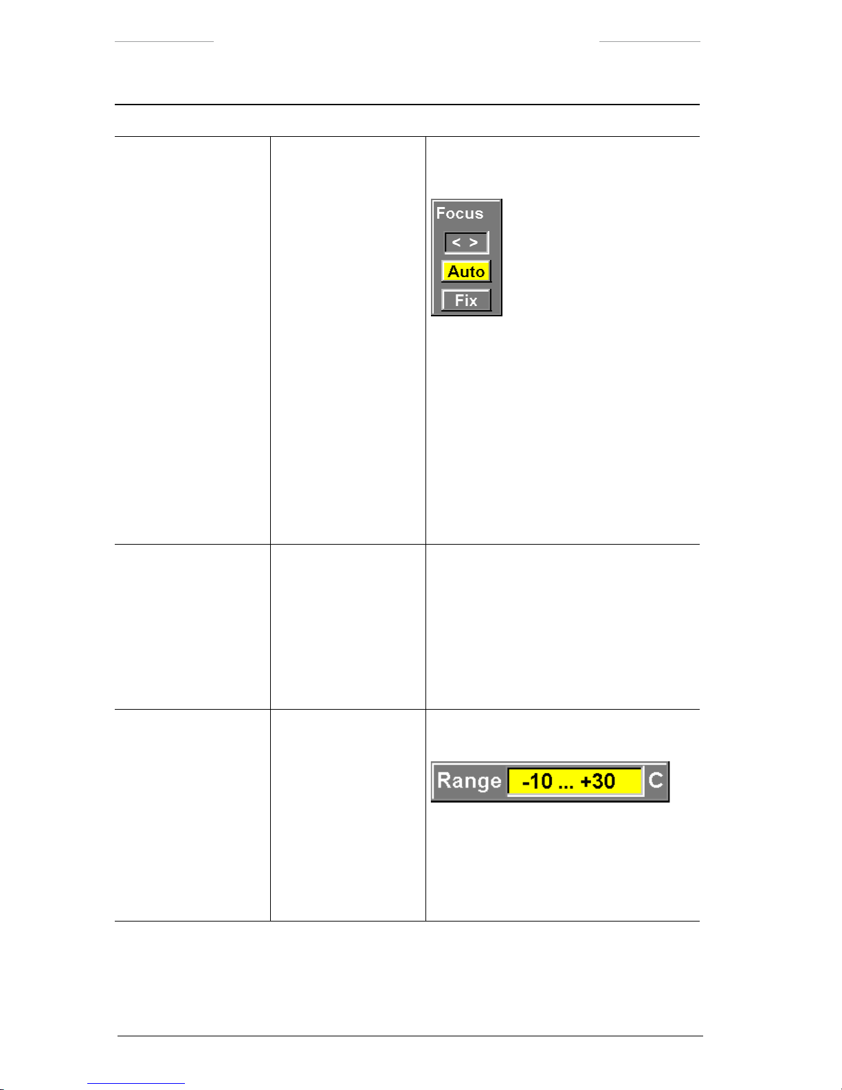
Ranger HRC™ operator´s manual – IR Camera software
88 Publ. No. TM 614 006 699 Rev B – ENGLISH (EN) – Oct 30. 2008
Menu choice Possible choices Explanation
Focus… – Press the ENTER button to display the Focus
dialog box.
• To change the focus, select the top button and then press the navigation pad
left/right
• To autofocus the camera, select the
Auto
button and press the navigation pad
left/right
• To set the camera to the xed focus
position, select the Fix button and press
the navigation pad left/right
•
To leave the dialog box, press ENTER
NUC – Press the ENTER button to make the camera
perform a NUC, i.e. a non-uniformity correction.
The NUC function performs an internal cali
bration to correct for image non-uniformities
that arise due to the slightly different offset
characteristics occurring from detector to
detector within the array.
Range... – Press the ENTER button to display the Range
dialog box.
The camera has been calibrated to be used
for different temperature ranges. Use the
navigation pad to select between the different
temperature ranges.
• Press the ENTER button to conrm.
Page 99

Ranger HRC™ operator´s manual – IR Camera software
Publ. No. TM 614 006 699 Rev B – ENGLISH (EN) – Oct 30. 2008 89
Menu choice Possible choices Explanation
Freeze – Press the ENTER button to freeze the image.
When the image is frozen, this menu item will
be displayed as
Live.
Manual adjust
Automatic adjust
– To switch between manual adjustment and
automatic adjustment of the image, press
ENTER.
The current adjustment mode will be dis
-
played in the top line status indicator.
Adjust image... – Select Adjust image and press ENTER to
display the Adjust image dialog box. In this
dialog box you can change level and span, or
the corresponding brightness and contrast.
The appearance of this dialog box depends
on the settings for Adjust mode and Color
distribution in the Image Setup dialog box.
If
Manual and Histogram or Linear are
selected in the Image Setup dialog box,
you can change level and span by using the
navigation pad.You can also carry out an oneshot autoadjust maneuver.
If Level/Span and Histogram or Linear are
selected in the Image Setup dialog box, you
can change brightness and contrast by using
the navigation pad. This will be indicated by
AUTO* in the top line status bar.
Page 100
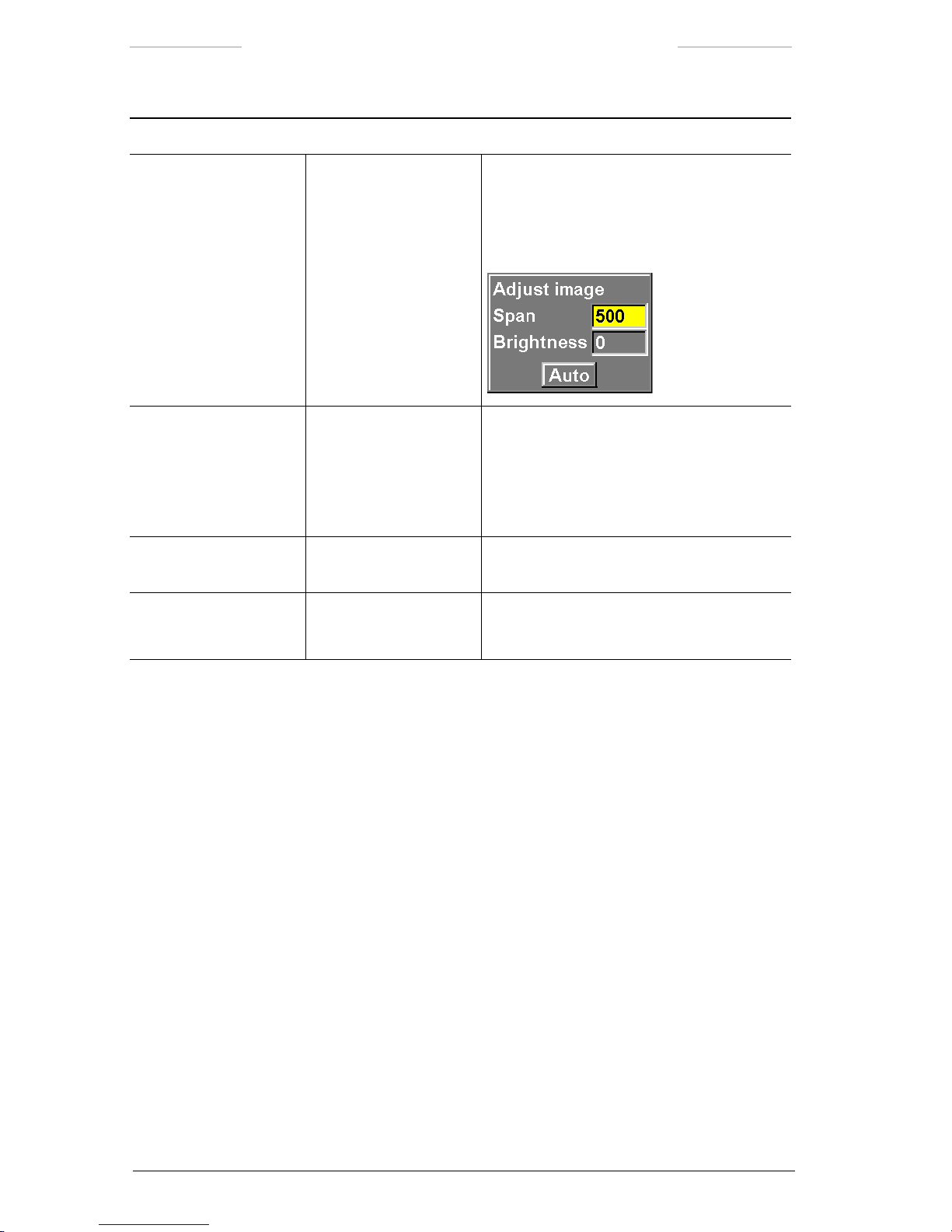
Ranger HRC™ operator´s manual – IR Camera software
90 Publ. No. TM 614 006 699 Rev B – ENGLISH (EN) – Oct 30. 2008
Menu choice Possible choices Explanation
Adjust image...
(continue)
If
Level and Histogram or Linear are
selected in the Image setup dialog box, you
can change span and brightness by using the
navigation pad.You can also carry out an oneshot autoadjust maneuver.
Palette... • Rainbow
• Rainbow HC
• Gray (white hot)
• Iron
Use the navigation pad to select different IR
palettes.
Press the ENTER button to conrm.
Invert Palette – Press the ENTER button to invert the current
palette
Hide graphics
Show graphics
– When graphics are hidden, this command will
be Show graphics.
8.3.1.1 To consider when auto focusing
To make it possible for the camera to auto focus properly; there are a few
things to consider.
• The default area that the camera uses when auto focusing is a 80×60
pixel box, centered vertically and horizontally on the screen.
• The camera will have difculties auto focusing when the image has
low contrasts between different areas.
• Keep the camera steady when auto focusing.
 Loading...