

Page 1
Ranger
R Series Radars
Mid-Range Perimeter
Surveillance Radar
Operator Manual
R1, R2, R3, R 3 D , R5, R 5 D , R4SS-X, R6SS-X, R8SS-X & R20SS
®
FLIR Radars Inc.
4176 Boul. Industriel
Laval, QC H7L 6H1
: +1(450) 662.7557
: radars@flir.com
www.flir.com
Document Number: 910-0001-00-MAN Version: R06
Issue Date: March 2019
This document is proprietary to FLIR Radars Inc. This document and data disclosed herein or herewith is not to be reproduced,
used, or disclosed in whole or in part to anyone without the written permission of FLIR Radars Inc.
Page 2

©2019 FLIR Radars Inc.
Reference #910-0001-00-MAN-R06
This documentation is provided as a component of the FLIR Radars Inc. All parties or individuals who are
in possession of the documentation accept in full and without exception or limitation the FLIR Radars Inc.
unrestricted rights of ownership of this material. This documentation is not available by any other means
except by license which is only available from FLIR Radars Inc. Under no circumstances may any part or
the whole of this documentation be reproduced, stored in a retrieval system, transmitted, copied,
modified, distributed, displayed, sold, licensed, published or derivative works created therefrom in any
form or by any means electronic, mechanical, recording, or otherwise without the written permission of
FLIR Radars Inc. being obtained in advance.
Information contained in this document pertains to a Canadian origin product that is controlled as "dual
use" by the Canadian government. However, when in the United States or possessed by a US person, it
may be considered a defense article from the US Government's perspective. US government
authorization may be required for re-transfer to a foreign person. If you have any questions, please
contact FLIR's Global Trade Compliance group at exportquestions@flir.com .
It is expressly forbidden for the holder of this documentation to use it either in its entirety or in part or
any graphics to provide training or tuition, assistance or knowledge transfer to any other party
whatsoever, or for marketing of promotional literature or material of any type whatsoever without the
prior written permission of FLIR Radars Inc. Use of this documentation in any manner inconsistent with
the user manual and related documentation is strictly prohibited. Use of the documentation is not
transferable.
910-0001-00-MAN -R06 FLIR Proprietary Information Page 2 of 81
Information contained in this document pertains to a Canadian origin product that is controlled as "dual use" by the Canadian government. However,
when in the United States or possessed by a US person, it may be considered a defense article from the US Government's perspective. US government
authorization may be required for re-transfer to a foreign person. If you have any questions, please contact FLIR's Global Trade Compliance group
at exportquestions@flir.com .
Page 3

CONTACT INFORMATION
Toll Free North America
When sending an e-mail (), please include:
Contact info (e-mail, phone, fax, other as required)
Product model and software version number
If possible, the serial number of the product
A description of the problem/issue
Data recordings and/or log files, if available
Any other pertinent information
1.866.657.4554
+1(450) 662.7557
+1(450) 622.7134
www.flir.com
radars@flir.com
DISPOSAL
Dispose in accordance with the laws and regulations applicable in your
jurisdiction.
910-0001-00-MAN -R06 FLIR Proprietary Information Page 3 of 81
Information contained in this document pertains to a Canadian origin product that is controlled as "dual use" by the Canadian
government. However, when in the United States or possessed by a US person, it may be considered a defense article from the US Government's
perspective. US government authorization may be required for re-transfer to a foreign person. If you have any questions, please contact FLIR's
Global Trade Compliance group at exportquestions@flir.com .
Page 4
REVISION RECORD TABLE
Manual Revision ECO # Pages Description of Modification
1.0 13-008 All PSR Software Version 6.1.0
2.0 All Insertion of ITAR statement
3.0 14-001 All
Add "FLIR Proprietary Information" to footer
4.0 16-025 All Added information for R6SS and R6SS-U
5.0 18-010 All Added 3D, updated R6 variants
6.0 18-016 11, 12
Corrected safety distances
Added note for camera connector of 777 PT
910-0001-00-MAN-R06 FLIR Proprietary Information Page 4 of 81
Information contained in this document pertains to a Canadian origin product that is controlled as "dual use" by the Canadian
government. However, when in the United States or possessed by a US person, it may be considered a defense article from the US Government's
perspective. US government authorization may be required for re-transfer to a foreign person. If you have any questions, please contact FLIR's
Global Trade Compliance group at exportquestions@flir.com .
Page 5
The following symbols are used throughout this document:
Caution!
The CAUTION symbol is used to alert the reader to situations where a hazard to personnel safety may
arise.
WARNING!
The WARNING symbol is used to alert the reader to situations where equipment damage is imminent
if a recommended process is not followed or alert the reader of a process that will alter or reset
current configuration of a specific setup.
DANGER!
The DANGER symbol is used to alert the reader to situations where a hazard to personnel may result
in serious injury possibly leading to death.
Disclaimer!
Disclaimers provide a means of specifying limitations or other requirements on equipment.
Note
Notes comprise additional information to assist the reader in the use or understanding of the
equipment or subject.
910-0001-00-MAN-R06 FLIR Proprietary Information Page 5 of 81
Information contained in this document pertains to a Canadian origin product that is controlled as "dual use" by the Canadian
government. However, when in the United States or possessed by a US person, it may be considered a defense article from the US Government's
perspective. US government authorization may be required for re-transfer to a foreign person. If you have any questions, please contact FLIR's
Global Trade Compliance group at exportquestions@flir.com .
Page 6

DEFINITIONS AND ACRONYMS
AXML Amphitech eXtensible Markup Language
BIT Built-in Test
CE Refers to CE marking, a conformity mark in Europe
CFAR Constant False Alarm Rate
Doppler Doppler effect. Also refers to Doppler radar operation mode, where target speed is used to
reject fixed clutter.
FastScan Non-Doppler scanning mode featuring a fast update rate
FCC Federal Communications Commission (usually refers to the US agency)
FMCW Frequency Modulated Continuous Wave
GPS Global Positioning System
GUI Graphical User Interface
IP Internet Protocol
MBPS MegaBits Per Second
MMW Millimeter Wave
PPI Plan Position Indicator
PPS Pulse Per Second
PSR Perimeter Surveillance Radar
RCS Radar Cross Section
RF Radio Frequency
VDC Volts of Direct Current
XML Extensible Markup Language
910-0001-00-MAN-R06 FLIR Proprietary Information Page 6 of 81
Information contained in this document pertains to a Canadian origin product that is controlled as "dual use" by the Canadian
government. However, when in the United States or possessed by a US person, it may be considered a defense article from the US Government's
perspective. US government authorization may be required for re-transfer to a foreign person. If you have any questions, please contact FLIR's
Global Trade Compliance group at exportquestions@flir.com .
Page 7

TABLE OF CONTENTS
1 INTRODUCTION ........................................................................................ 11
1.1 SAFETY ISSUES ......................................................................................... 11
2 PSR SYSTEM OPERATION ............................................................................. 13
2.1 RADAR APPLICATION MANAGER ...................................................................... 13
2.1.1 Application Status ........................................................................ 14
2.1.2 Application Name ......................................................................... 14
2.1.3 Image Name ............................................................................... 14
2.1.4 Application Running Time ............................................................... 14
2.1.5 Application Parameters ................................................................. 14
2.1.6 Event Log Window ........................................................................ 14
2.2 RADAR CONSOLE ....................................................................................... 15
2.2.1 Operator Login ............................................................................ 15
2.2.2 Radar Mode Change (applies only to R3D and R5D radars) ........................ 22
2.2.3 Radar Mode Change (applies only to R4SS-X, R6SS-X and R8SS-X radars) ....... 24
2.2.4 Regular Scan Mode Change (applies only to R4SS-X, R6SS-X, R8SS-X and R20SS
radars) 25
2.2.5 Editing Zones .............................................................................. 29
2.2.6 PPI Display ................................................................................. 42
2.2.7 Intruders and Targets .................................................................... 55
2.2.8 Recording Data ............................................................................ 61
2.2.9 Radar Operations ......................................................................... 64
2.2.10 Radar Configuration Parameters ....................................................... 66
3 TROUBLESHOOTING ................................................................................... 80
910-0001-00-MAN-R06 FLIR Proprietary Information Page 7 of 81
Information contained in this document pertains to a Canadian origin product that is controlled as "dual use" by the Canadian
government. However, when in the United States or possessed by a US person, it may be considered a defense article from the US Government's
perspective. US government authorization may be required for re-transfer to a foreign person. If you have any questions, please contact FLIR's
Global Trade Compliance group at exportquestions@flir.com .
Page 8

LIST OF FIGURES
Figure 1 - Radar Application Manager Main Window ............................................................... 13
Figure 2 - Login Operator Mode ....................................................................................... 15
Figure 3 - Radar Console Displaying Available Radars ............................................................. 15
Figure 4 - Radar Lexicon ............................................................................................... 18
Figure 5 – Radar Control ................................................................................................ 21
Figure 6 - Radar Information .......................................................................................... 21
Figure 7 - Changing Range in FastScan Mode ....................................................................... 22
Figure 8 - Changing Range and Time-On-Target in Doppler Mode ............................................... 23
Figure 9 - Changing Mode on a R6SS or R6SS-U ..................................................................... 24
Figure 10 - Changing Range and Time-On-Target on a R4SS-X, R6SS-X or R8SS-X ............................ 24
Figure 11 - Pan/Tilt Positioner Enable Parameter ................................................................. 25
Figure 12 - Fixed Mode Configuration Parameters ................................................................. 26
Figure 13 - Continuous Mode Configuration Parameters .......................................................... 27
Figure 14 - Alternating Mode Configuration Parameters .......................................................... 28
Figure 15 - Contact and Intrusion Zones ............................................................................ 30
Figure 16 – Edit Menu ................................................................................................... 31
Figure 17 - Creating a Zone (Step 1 of 4) ............................................................................ 32
Figure 18 - Creating a Zone (Step 2 of 4) ............................................................................ 33
Figure 19 - Creating a Zone (Step 3 of 4) ............................................................................ 34
Figure 20 - Creating a Zone (Step 4 of 4) ............................................................................ 35
Figure 21 - Changing Segment Adding Order ....................................................................... 36
Figure 22 - Edit Menu Commands ..................................................................................... 37
Figure 23 - Edit Menu Commands ..................................................................................... 37
Figure 24 - Zone Edition Context ..................................................................................... 38
Figure 25 - Modifying a Zone (Step 1 of 2) .......................................................................... 39
Figure 26 - Modifying a Zone (Step 2 of 2) .......................................................................... 40
Figure 27 - Edit Menu Commands ..................................................................................... 41
Figure 28 - View Menu Commands .................................................................................... 42
Figure 29 - Cursor Position Indicator ................................................................................. 43
Figure 30 - Radar PPI (Continuous) ................................................................................... 44
Figure 31 - Radar PPI (Snapshot) Mode .............................................................................. 45
Figure 32 - Background Map ........................................................................................... 47
Figure 33 - PPI Color Palette........................................................................................... 48
Figure 34 – Radar Location ............................................................................................. 48
Figure 35 - Range Rings ................................................................................................. 49
Figure 36 - View Menu Commands .................................................................................... 50
Figure 37 - Intrusion Zones (Red Boundary) ......................................................................... 51
Figure 38 - Contact Zones (Yellow Boundary) ....................................................................... 52
Figure 39 - Intrusion Zones Coverage ................................................................................ 53
Figure 40 - Contact Zones Coverage .................................................................................. 54
Figure 41 - Description of Intruder and Target Symbols .......................................................... 55
Figure 42 - Selected Intruder / Target Status Line Information ................................................ 56
Figure 43 - Targets/Intruders List View .............................................................................. 56
Figure 44 - Targets/Intruders Tree View ............................................................................. 57
910-0001-00-MAN-R06 FLIR Proprietary Information Page 8 of 81
Information contained in this document pertains to a Canadian origin product that is controlled as "dual use" by the Canadian
government. However, when in the United States or possessed by a US person, it may be considered a defense article from the US Government's
perspective. US government authorization may be required for re-transfer to a foreign person. If you have any questions, please contact FLIR's
Global Trade Compliance group at exportquestions@flir.com .
Page 9

Figure 45 - Track Recovery Enable Parameter ...................................................................... 58
Figure 46 - Tracks Being Coasted ...................................................................................... 59
Figure 47 - Track Being Recovered .................................................................................... 59
Figure 48 - Radar Contacts ............................................................................................. 60
Figure 49 - Record Targets/Intruders Log Command .............................................................. 61
Figure 50 - Targets/Intruders Log File Example .................................................................... 61
Figure 51 - Record Radar Data Menu ................................................................................. 62
Figure 52 - Record Radar Data Duration ............................................................................. 62
Figure 53 - Radar Standby and Transmit Commands ............................................................... 63
Figure 54 - Logs Window ............................................................................................... 65
Figure 55 - Setup Menu ................................................................................................. 65
Figure 56 - Logs File Example ......................................................................................... 65
Figure 57 - Parameters Window ....................................................................................... 72
Figure 58 - Changing Parameter Values .............................................................................. 73
Figure 59 - Programming Unit Parameters .......................................................................... 74
Figure 60 - Current Parameter Group Commands .................................................................. 75
Figure 61 - Default Parameter Group Commands .................................................................. 76
Figure 62 - Exporting Radar Parameters (Step 2) .................................................................. 77
Figure 63 - Exporting Radar Parameters (Step 3) .................................................................. 78
Figure 64 - Exporting Radar Parameters (Steps 4 and 5) ......................................................... 78
Figure 65 - Exporting Radar Parameters (Step 6) .................................................................. 79
910-0001-00-MAN-R06 FLIR Proprietary Information Page 9 of 81
Information contained in this document pertains to a Canadian origin product that is controlled as "dual use" by the Canadian
government. However, when in the United States or possessed by a US person, it may be considered a defense article from the US Government's
perspective. US government authorization may be required for re-transfer to a foreign person. If you have any questions, please contact FLIR's
Global Trade Compliance group at exportquestions@flir.com .
Page 10

LIST OF TABLES
Table 1 - Radar Console Functions vs. Login Level ................................................................. 17
Table 2 - Radar Icons and Messages .................................................................................. 20
Table 3 – PPI Commands ............................................................................................... 46
Table 4 - Configuration Parameters Groups ......................................................................... 66
Table 5 - Radar Configuration Parameters Access vs. Login Level .............................................. 68
Table 6 - Configuration Parameter Descriptions .................................................................... 71
910-0001-00-MAN-R06 FLIR Proprietary Information Page 10 of 81
Information contained in this document pertains to a Canadian origin product that is controlled as "dual use" by the Canadian
government. However, when in the United States or possessed by a US person, it may be considered a defense article from the US Government's
perspective. US government authorization may be required for re-transfer to a foreign person. If you have any questions, please contact FLIR's
Global Trade Compliance group at exportquestions@flir.com .
Page 11
1 INTRODUCTION
This manual describes the Perimeter Surveillance Radar (PSR) system operation. The Operator Manual is
intended for an audience of technically qualified personnel. For installation and configuration of the radar
system, or for more advanced functions, please refer to the installation manual of your specific radar.
Note
Please note that the generic product name “radar” is used throughout this manual for ease of
reading. The given information is valid for products Ranger R1, R2, R3, R3D, R5, R5D, R4SS-X, R6SS-X,
R8SS-X and R20SS unless noted otherwise. Also, the -X in R4SS-X, R6SS-X and R8SS-X refers to the 3
possible variants of each radar, for example R6SS-X can refer to R6SS, R6SS-U or R6SS-3D.
1.1 SAFETY ISSUES
This equipment generates Radio Frequency energy and is intended for outdoor installations only. Based
on limits specified by the Federal Communication Commission (FCC) on Radio Frequency (RF) Emissions,
findings from tests conducted conclude that the R1, R2, R3, R3D, R5, R5D, R4SS-X, R6SS-X, R8SS-X and
R20SS do not represent any safety hazards and are therefore safe for human exposure, provided the
following conditions are met:
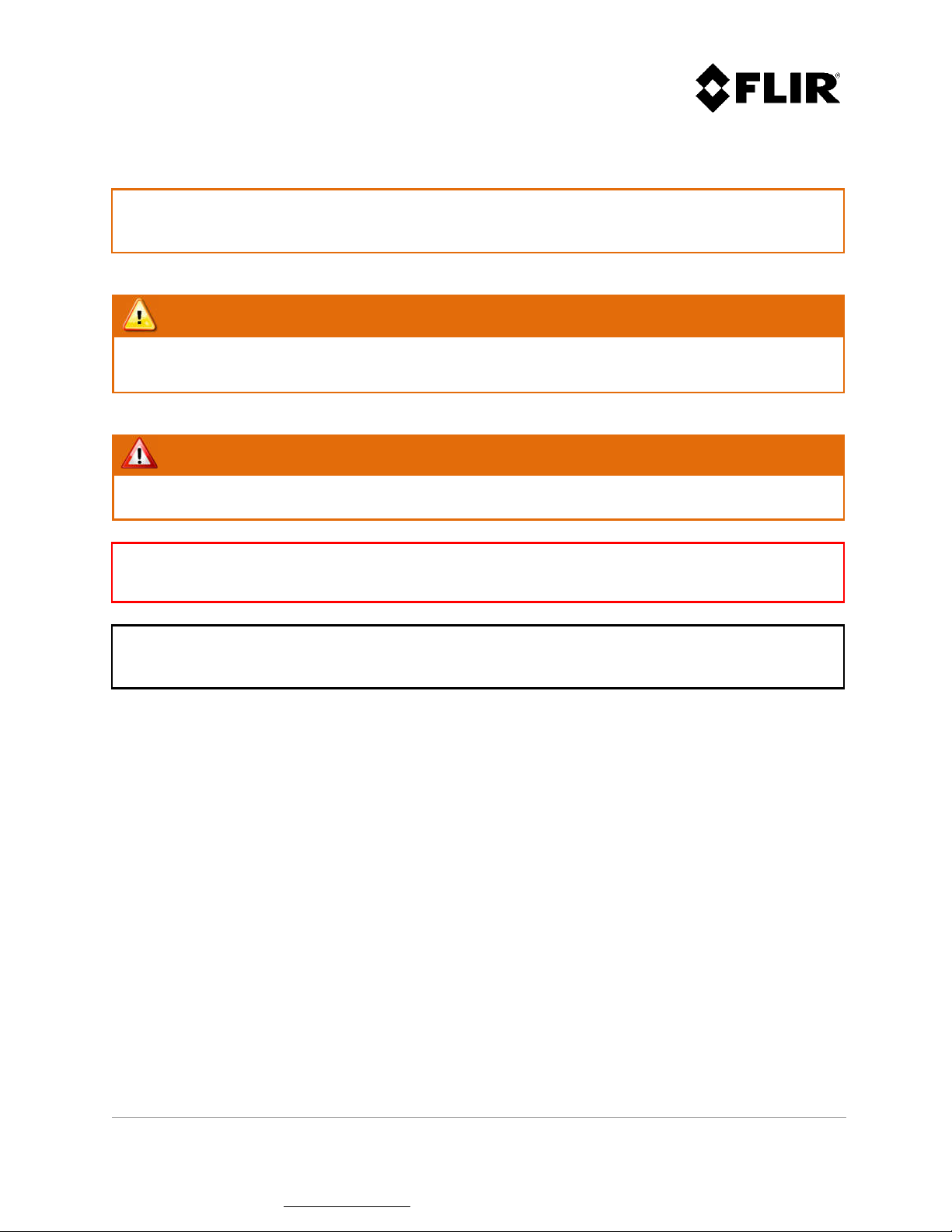
Caution!
The installation must provide a separation distance from all persons and must not be co-located or operated in
conjunction with any other antennas or transmitters. This safety distance complies with the FCC Limits for
Maximum Permissible Exposure (MPE) for general population / uncontrolled exposure.
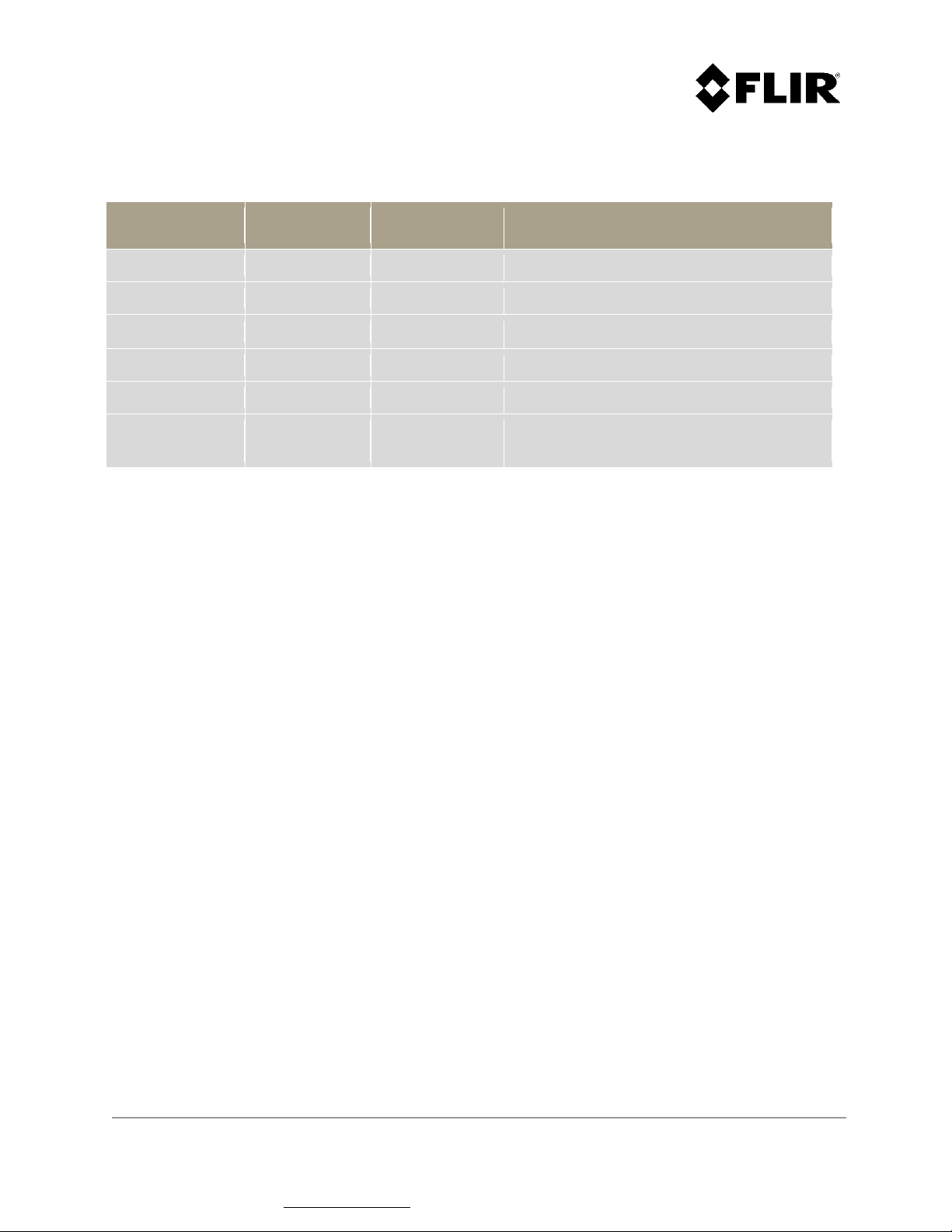
Safety Distances
Output
Power
Frequency
Band
Controlled Exposure General Population
FCC MPE distance (cm)
R20SS (921-0041-00-R0X) 25 Watts X 170 400
R20SS (921-0041-22-R0X)
R20SS (921-0041-23-R0X)
25 Watts X 170 400
R20SS (921-0041-30-R0X) 8 Watts X 90 200
R4SS, R6SS, R8SS
(921-0071-XX-R0X)
R4SS-U/3D, R6SS-U/3D,
R8SS-U/3D
(921-0071-XX-R0X)
R1,R2,R3, R3D
(921-0011-06-R0X)
R3D (921-0011-06-R06)
(Doppler)
2/8/25
Watts
2/8/25
Watts
X 50 / 90 / 170 100 / 200 / 400
X 25 / 40 / 80 45 / 80 / 180
0.8 Watt Ka 22 22
0.8 Watt Ka 22 22
R5 (921-0031-01-R07) 0.56 Watt Ka 10 20
910-0001-00-MAN-R06 FLIR Proprietary Information Page 11 of 81
Information contained in this document pertains to a Canadian origin product that is controlled as "dual use" by the Canadian
government. However, when in the United States or possessed by a US person, it may be considered a defense article from the US Government's
perspective. US government authorization may be required for re-transfer to a foreign person. If you have any questions, please contact FLIR's
Global Trade Compliance group at exportquestions@flir.com .
Page 12
R5D (921-0031-02-R04)
(FastScan)
R5D (921-0031-02-R04)
(Doppler)
0.56 Watt Ka 13 28
0.56 Watt Ka 25 55
Note: theses distances are for guidance only
DISPOSAL
This product contains a lithium battery. Dispose in accordance with the laws and regulations applicable
in your jurisdiction.
WARNING!
The R4SS-X/R6SS-X/R8SS-X/R20SS pan/tilt positioner contains moving parts that can pinch fingers
and/or other body parts. Use caution when the pan/tilt positioner is powered on.
WARNING!
When using pan/tilt positioner 960-0037-00, ensure that the camera connector is connected to a
cable or properly capped, to prevent water ingress into the unit.
910-0001-00-MAN-R06 FLIR Proprietary Information Page 12 of 81
Information contained in this document pertains to a Canadian origin product that is controlled as "dual use" by the Canadian
government. However, when in the United States or possessed by a US person, it may be considered a defense article from the US Government's
perspective. US government authorization may be required for re-transfer to a foreign person. If you have any questions, please contact FLIR's
Global Trade Compliance group at exportquestions@flir.com .
Page 13
2 PSR SYSTEM OPERATION
This section covers the operation of the PSR Radar System using the Radar Console Application.
For details on how to perform radar installation, please refer to the installation manual of your specific
radar. For details on how to perform radar configuration, please refer to the Configuration Manual.
WARNING!
All the FLIR radars are intended for outdoor use only. Operating the radars inside, where there is no
sufficient air movement, may result in the radar overheating and generating an error.
2.1 RADAR APPLICATION MANAGER
The Radar Application Manager is typically used to start other application including the Radar Console.
For details on how to configure Radar Application Manager to monitor specific applications, please
refer to the Configuration Manual.
Figure 1 shows the Radar Application Manager main window. The following sections describe each
element.
Figure 1 - Radar Application Manager Main Window
910-0001-00-MAN-R06 FLIR Proprietary Information Page 13 of 81
Information contained in this document pertains to a Canadian origin product that is controlled as "dual use" by the Canadian
government. However, when in the United States or possessed by a US person, it may be considered a defense article from the US Government's
perspective. US government authorization may be required for re-transfer to a foreign person. If you have any questions, please contact FLIR's
Global Trade Compliance group at exportquestions@flir.com .
Page 14

2.1.1 Application Status
The application status will read either ACTIVE, UNLINK or TIMEOUT. An ACTIVE application is
monitored by the Application Manager and will automatically re-start in the event of a crash, power
outage or system failure. An UNLINK status reflects an application started manually and that is not
monitored by the Application Manager. If the application closes or hangs, the Application Manager will
not re-start it. When either application with a status of ACTIVE or UNLINK closes or hangs, its status
changes to TIMEOUT.
2.1.2 Application Name
Displays the name (e.g. Radar Console, Radar Server, etc.) for each application listed.
2.1.3 Image Name
The image name contains the executable file name of each application.
2.1.4 Application Running Time
The application running time displays the duration that each application has been running. When an
application is re-started by the Radar Application Manager, the duration is reset to zero. Also, this
value is reset to zero every day at midnight.
2.1.5 Application Parameters
The application parameters field contains the command-line parameters used to start monitored
applications.
2.1.6 Event Log Window
The event log window contains a list of events that occurred since start-up of the Radar Application
Manager. These events include the (re)starting of applications, timeouts, etc.
910-0001-00-MAN-R06 FLIR Proprietary Information Page 14 of 81
Information contained in this document pertains to a Canadian origin product that is controlled as "dual use" by the Canadian
government. However, when in the United States or possessed by a US person, it may be considered a defense article from the US Government's
perspective. US government authorization may be required for re-transfer to a foreign person. If you have any questions, please contact FLIR's
Global Trade Compliance group at exportquestions@flir.com .
Page 15
2.2 RADAR CONSOLE
The Radar Console allows the configuration of radar assemblies, the configuration of detection and
intrusion zones, and the visualization of radar sectors, targets and intruders.
2.2.1 Operator Login
This application requires the user to login to access most of its functions, as shown in Figure 2. Four (4)
login levels are supported by Radar Console. This document covers the two (2) first levels (Operator
and Administrator).
Figure 2 - Login Operator Mode
Once logged in, the radar console screen displays available radars in the left pane.
Figure 3 - Radar Console Displaying Available Radars
910-0001-00-MAN-R06 FLIR Proprietary Information Page 15 of 81
Information contained in this document pertains to a Canadian origin product that is controlled as "dual use" by the Canadian
government. However, when in the United States or possessed by a US person, it may be considered a defense article from the US Government's
perspective. US government authorization may be required for re-transfer to a foreign person. If you have any questions, please contact FLIR's
Global Trade Compliance group at exportquestions@flir.com .
Page 16
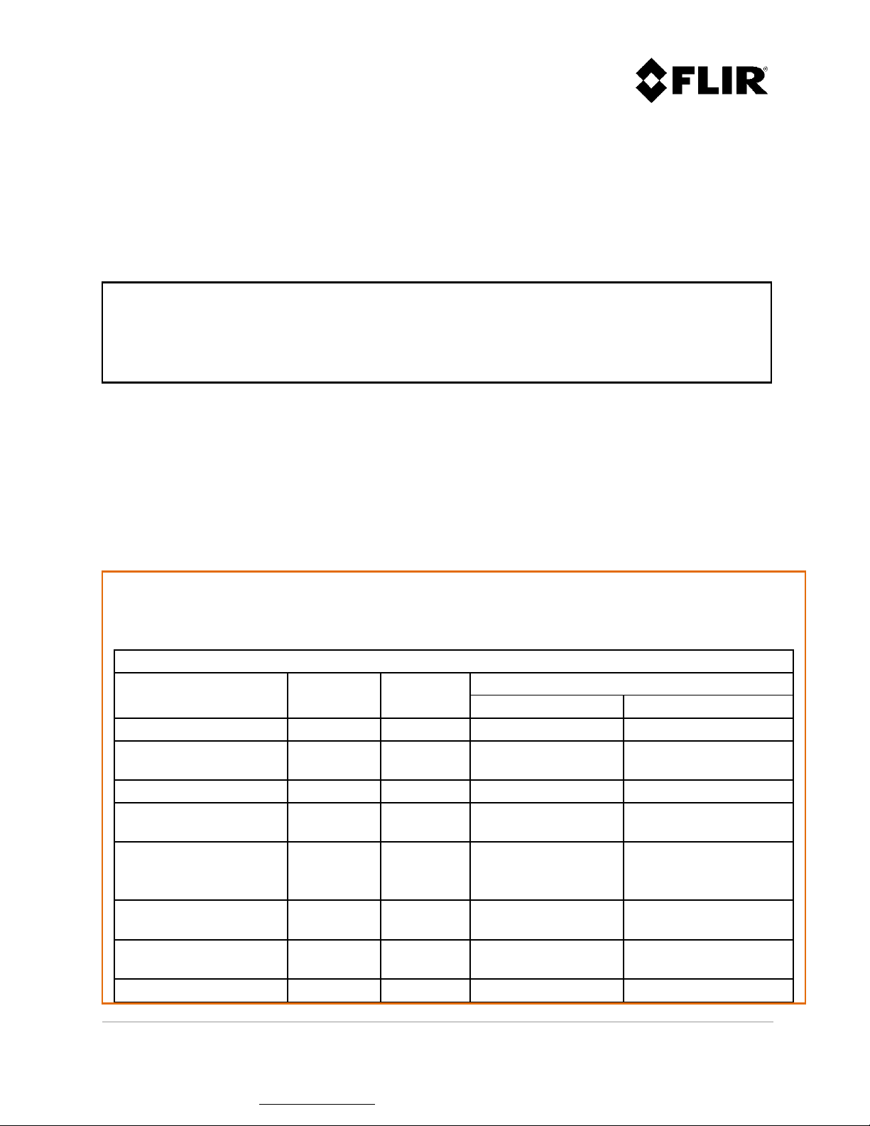
Table 1 shows the functions that are accessible according to the login level. The Direct column refers
to functions accessible when the Radar Console is connected directly to the radar, and the Server
column refers to functions accessible when the Radar Console is connected to the radar via the Radar
Server.
Menu
Item
Function
Operator Admin Operator Admin
Console Console (DIRECT)
Edit Edit / create intrusion zones x
View
View intruders / targets x x
View tracks x x
View identification number x x
View radar PPI x x x x
Change PPI color palette x x
View radar location x x x x
View range rings x x x x
Intrusion / contact coverage x x
View background map x x x x
View intrusion / contact zones x x
View contacts x
Tools
Targets / intruders list view x x
Targets / intruders tree view x x
Replay radar data x x
Explore Logs directory x x x x
Explore Maps directory x x x x
Explore Capture directory x x x x
Explore Recording directory x x x x
Close Log Windows (Console) x x
Erase Logs (Console, Memory) x x
Export Parameters (All) x x
Maintenance Command Dialog x x
Setup
Set Logs directory x x
Set Maps directory x x
Set Capture directory x x
Set Recording directory x x
TRaCS License Activation x x
910-0001-00-MAN-R06 FLIR Proprietary Information Page 16 of 81
Information contained in this document pertains to a Canadian origin product that is controlled as "dual use" by the Canadian
government. However, when in the United States or possessed by a US person, it may be considered a defense article from the US Government's
perspective. US government authorization may be required for re-transfer to a foreign person. If you have any questions, please contact FLIR's
Global Trade Compliance group at exportquestions@flir.com .
Page 17
Dialog
Right
Set radar to XMIT / STBY x x
mouse
click on
radar icon
Reset radar x x
Configure radar parameters x x x x
Set unit position from GPS x x
Set Radar Server time from
GPS
x
Enable / disable ICD-0100 x
Enable / disable AXML x
Record targets / intruders x
Record radar data x x
Reset communication statistics x x
Loader x
Table 1 - Radar Console Functions vs. Login Level
2.2.1.1 Radar Symbology
This section defines the symbology for the radar icon located in the left-hand column of the radar
console. Colors have a specific meaning as well as the information embedded in the icon. Figure 4
provides an icon lexicon describing the various color codes and symbols.
910-0001-00-MAN-R06 FLIR Proprietary Information Page 17 of 81
Information contained in this document pertains to a Canadian origin product that is controlled as "dual use" by the Canadian
government. However, when in the United States or possessed by a US person, it may be considered a defense article from the US Government's
perspective. US government authorization may be required for re-transfer to a foreign person. If you have any questions, please contact FLIR's
Global Trade Compliance group at exportquestions@flir.com .
Page 18
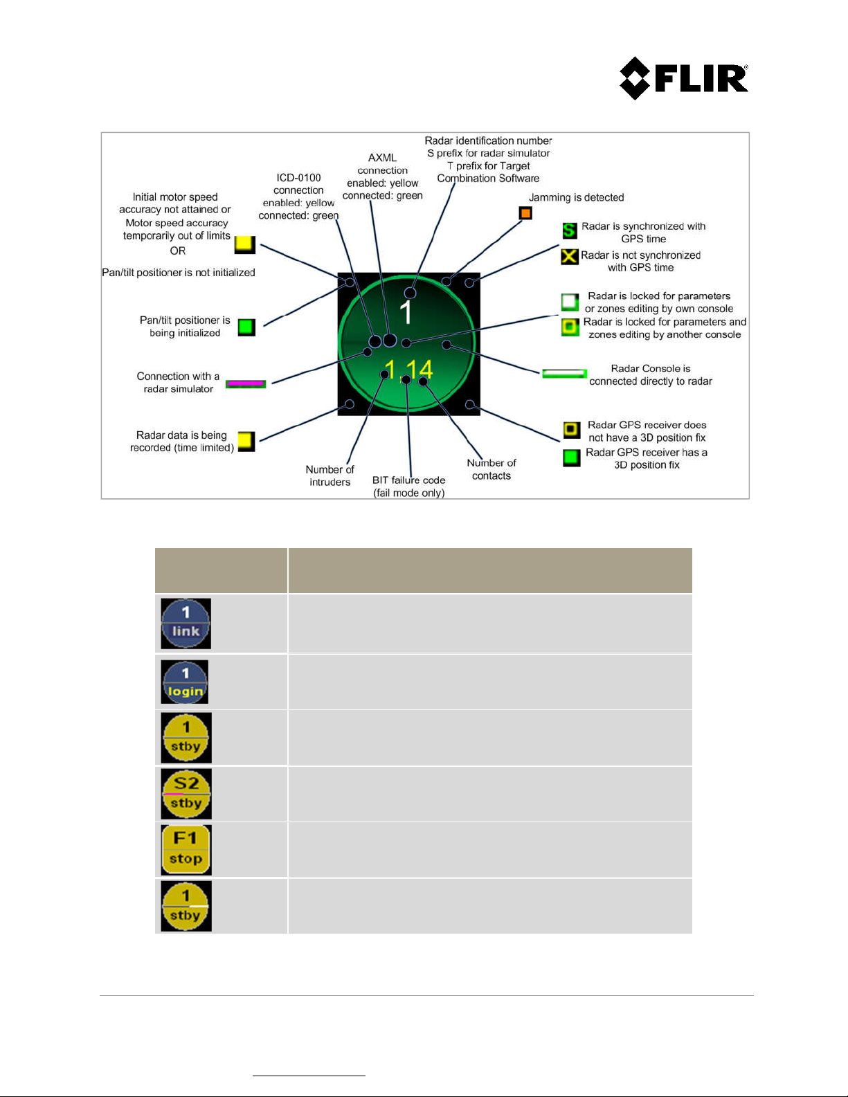
Figure 4 - Radar Lexicon
Radar Icon Message
Radar communication link is being established.
Radar connection is in progress.
Radar is in standby mode.
Radar simulator is in standby mode.
Track Combination Software is stopped.
Radar is in standby mode, and is connected directly to the
Radar Console application (instead of being connected
through the Radar Server application).
910-0001-00-MAN-R06 FLIR Proprietary Information Page 18 of 81
Information contained in this document pertains to a Canadian origin product that is controlled as "dual use" by the Canadian
government. However, when in the United States or possessed by a US person, it may be considered a defense article from the US Government's
perspective. US government authorization may be required for re-transfer to a foreign person. If you have any questions, please contact FLIR's
Global Trade Compliance group at exportquestions@flir.com .
Page 19
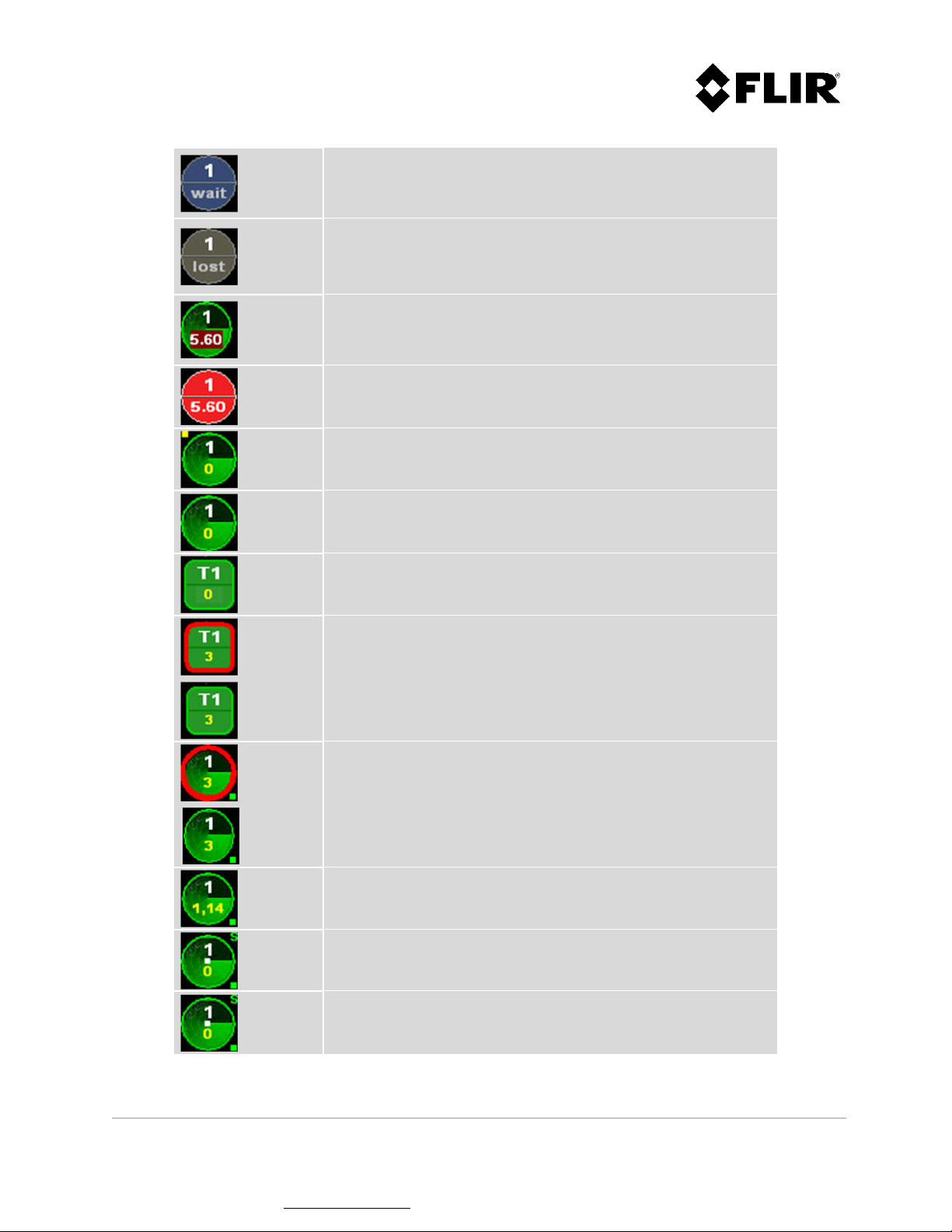
Communication with radar has been interrupted for at least
five (5) seconds.
Communication with radar is lost. The Operator can still
verify the last unit configured parameters and most recent
unit warnings. The Operator can manually delete the lost
icon.
Radar is in limited auto-recovery mode, with failure code
5.60. The Radar will try to recover from the failure
automatically.
Radar is in fail mode, with failure code 5.60. Refer to the
error codes section of the Installation Manual for explanatory
details.
Radar is transmitting and initial motor speed accuracy has not
yet been reached or is temporarily out of limits.
Radar is transmitting.
Target Combination Software is started (with TRaCS only).
Track Combination Software is started and tracking one (1)
intruder. Red circle around icon perimeter is blinking (with
TRaCS only).
Radar is transmitting and tracking three (3) intruders. Icon
perimeter (red circle) is blinking.
Radar is transmitting, tracking one (1) intruder and detecting
fourteen (14) contacts.
The radar is locked by this console for parameters and zones
editing.
The radar is locked by another console for parameters and
zones editing.
910-0001-00-MAN-R06 FLIR Proprietary Information Page 19 of 81
Information contained in this document pertains to a Canadian origin product that is controlled as "dual use" by the Canadian
government. However, when in the United States or possessed by a US person, it may be considered a defense article from the US Government's
perspective. US government authorization may be required for re-transfer to a foreign person. If you have any questions, please contact FLIR's
Global Trade Compliance group at exportquestions@flir.com .
Page 20
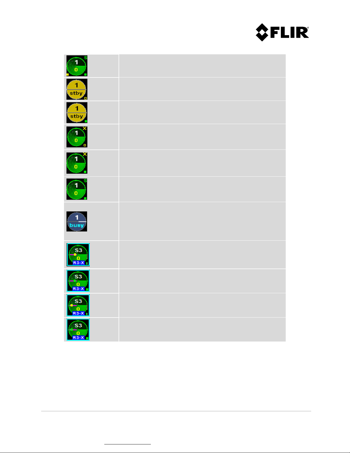
The Radar Console is recording data from this radar.
The radar possesses an embedded GPS receiver which cannot
have a 3D position fix. The radar is in standby mode.
The radar possesses an embedded GPS receiver which has a
3D position fix. The radar is in standby mode.
The radar possesses an embedded GPS receiver which cannot
have a 3D position fix. The radar is in transmit mode but
there is no synchronization with the GPS PPS signal.
The radar possesses an embedded GPS receiver which has a
3D position fix. The radar is in transmit mode but there is no
synchronization with the GPS PPS signal.
The radar possesses an embedded GPS receiver which has a 3D
position fix. The radar is in transmit mode and is synchronized
with the GPS PPS signal.
Radar is busy with another client.
The radar is accepting only one direct connection. This will be
shown only on a radar console used in direct mode when the
radar server or another console (direct) is connected to the
radar unit.
The radar has AXML connection enabled, but there are no
client connected through this connection.
The radar has AXML connection enabled, and there is a client
connected through this connection.
The radar has ICD-0100 connection enabled, but there are no
client connected through this connection.
The radar has ICD-0100 connection enabled, and there is a
client connected through this connection.
Table 2 - Radar Icons and Messages
910-0001-00-MAN-R06 FLIR Proprietary Information Page 20 of 81
Information contained in this document pertains to a Canadian origin product that is controlled as "dual use" by the Canadian
government. However, when in the United States or possessed by a US person, it may be considered a defense article from the US Government's
perspective. US government authorization may be required for re-transfer to a foreign person. If you have any questions, please contact FLIR's
Global Trade Compliance group at exportquestions@flir.com .
Page 21
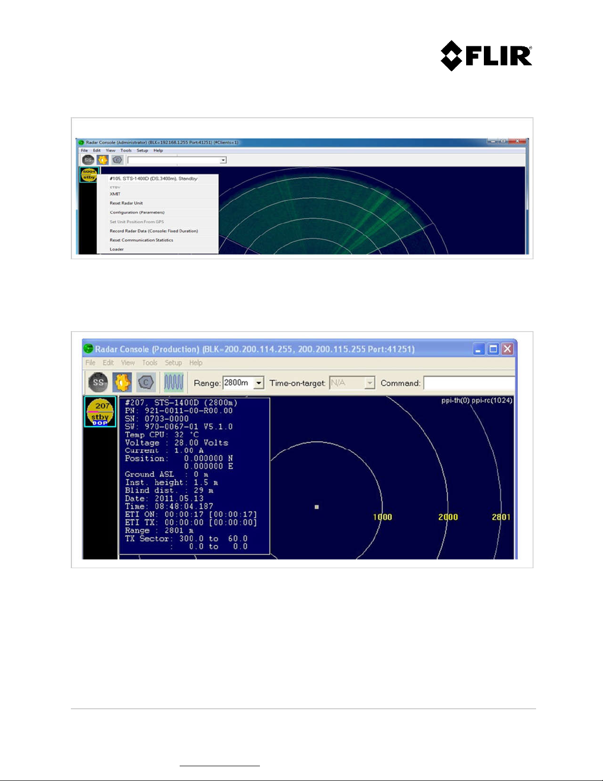
When right-clicking with the mouse over the radar icon, a menu displays as follows:
Figure 5 – Radar Control
When placing the mouse cursor over the radar icon, a radar information box displays as follows:
Figure 6 - Radar Information
910-0001-00-MAN-R06 FLIR Proprietary Information Page 21 of 81
Information contained in this document pertains to a Canadian origin product that is controlled as "dual use" by the Canadian
government. However, when in the United States or possessed by a US person, it may be considered a defense article from the US Government's
perspective. US government authorization may be required for re-transfer to a foreign person. If you have any questions, please contact FLIR's
Global Trade Compliance group at exportquestions@flir.com .
Page 22
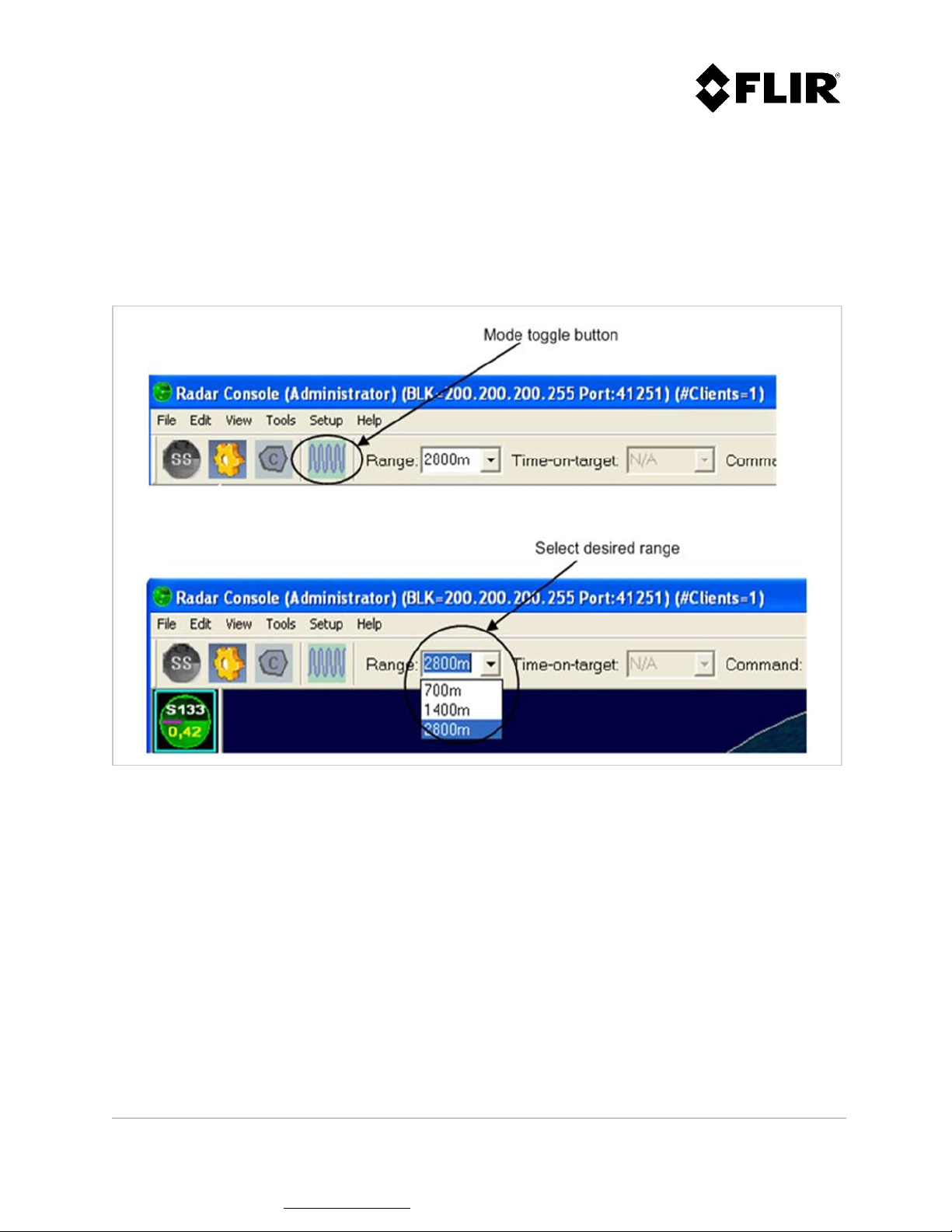
2.2.2 Radar Mode Change (applies only to R3D and R5D radars)
The R3D and R5D supports a non-Doppler mode, the FastScan mode, and three Doppler modes (short,
medium and long time-on-target). Changes of mode, range or time-on-target are made by using an icon
and a drop-down list in Radar Console, as shown in Figure 7 and Figure 8. The toggle button (Figure 7)
allows the user to conveniently switch between FastScan and Doppler modes.
Figure 7 - Changing Range in FastScan Mode
910-0001-00-MAN-R06 FLIR Proprietary Information Page 22 of 81
Information contained in this document pertains to a Canadian origin product that is controlled as "dual use" by the Canadian
government. However, when in the United States or possessed by a US person, it may be considered a defense article from the US Government's
perspective. US government authorization may be required for re-transfer to a foreign person. If you have any questions, please contact FLIR's
Global Trade Compliance group at exportquestions@flir.com .
Page 23
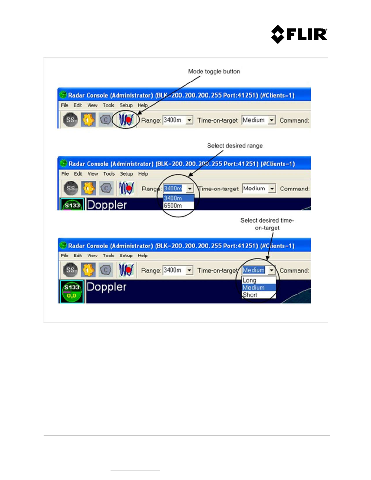
Figure 8 - Changing Range and Time-On-Target in Doppler Mode
910-0001-00-MAN-R06 FLIR Proprietary Information Page 23 of 81
Information contained in this document pertains to a Canadian origin product that is controlled as "dual use" by the Canadian
government. However, when in the United States or possessed by a US person, it may be considered a defense article from the US Government's
perspective. US government authorization may be required for re-transfer to a foreign person. If you have any questions, please contact FLIR's
Global Trade Compliance group at exportquestions@flir.com .
Page 24
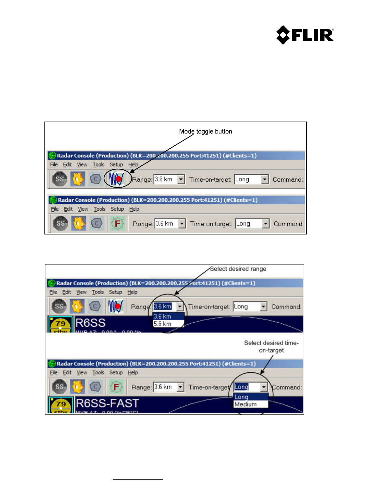
2.2.3 Radar Mode Change (applies only to R4SS-X, R6SS-X and R8SS-X radars)
The R4SS-X, R6SS-X and R8SS-X supports a FastScan mode and a regular (static or slow rotation) mode.
Changes of mode, range or time-on-target are made by using an icon and a drop-down list in Radar
Console, as shown in Figure 9 and Figure 10. The toggle button (Figure 9) allows the user to
conveniently switch between FastScan and regular modes.
Figure 9 - Changing Mode on a R6SS or R6SS-U
Figure 10 - Changing Range and Time-On-Target on a R4SS-X, R6SS-X or R8SS-X
910-0001-00-MAN-R06 FLIR Proprietary Information Page 24 of 81
Information contained in this document pertains to a Canadian origin product that is controlled as "dual use" by the Canadian
government. However, when in the United States or possessed by a US person, it may be considered a defense article from the US Government's
perspective. US government authorization may be required for re-transfer to a foreign person. If you have any questions, please contact FLIR's
Global Trade Compliance group at exportquestions@flir.com .
Page 25
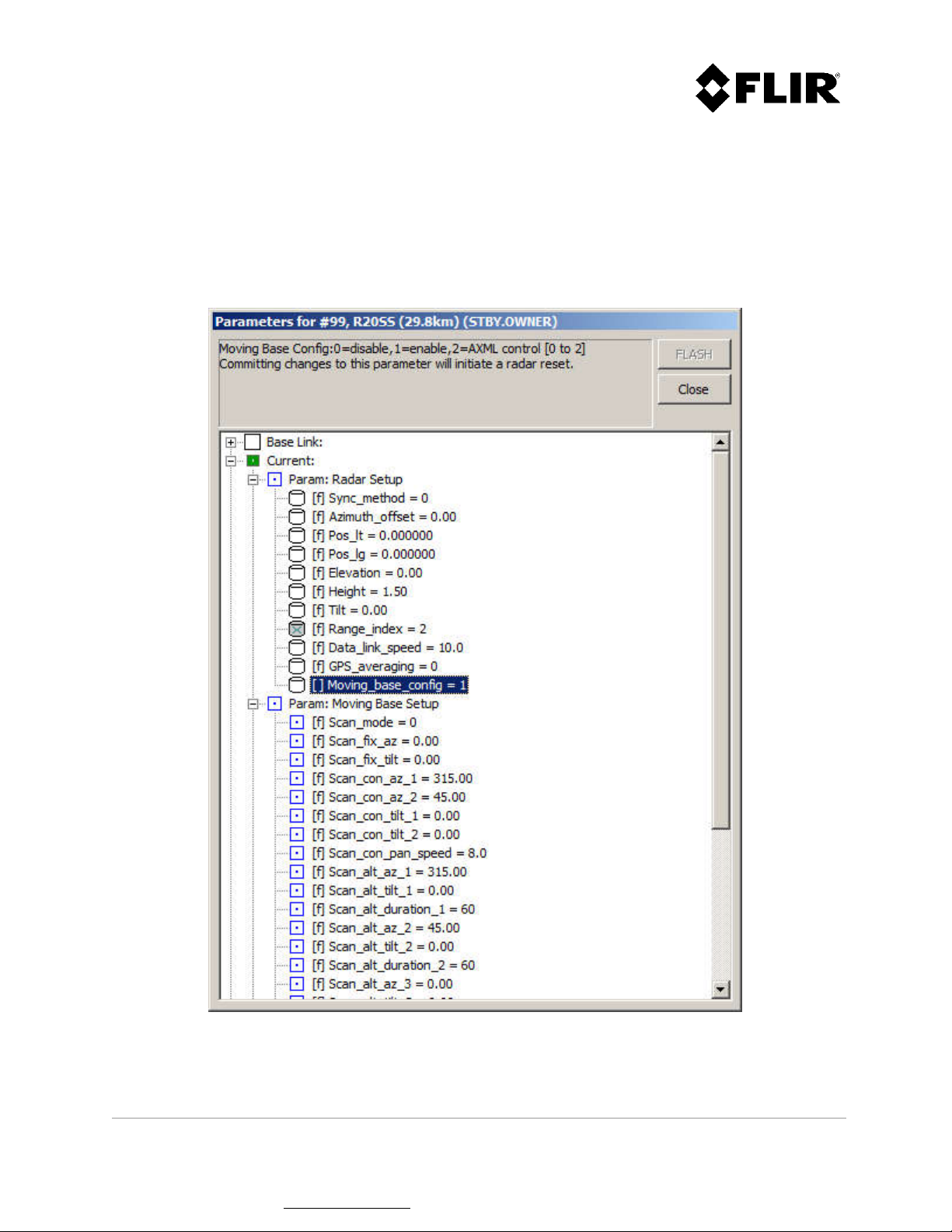
2.2.4 Regular Scan Mode Change (applies only to R4SS-X, R6SS-X, R8SS-X and R20SS radars)
When equipped with a pan/tilt positioner, the R4SS-X, R6SS-X, R8SS-X and R20SS supports 3 different
regular scan modes: fixed, continuous and alternating. In order to access those modes, the radar must
first be configured to activate the pan/tilt positioner. The parameter that enables the pan/tilt
positioner is called "Moving_base_config" (see Figure 11). Please refer to section 2.2.10 for instructions
on how to modify a configuration parameter.
Figure 11 - Pan/Tilt Positioner Enable Parameter
910-0001-00-MAN-R06 FLIR Proprietary Information Page 25 of 81
Information contained in this document pertains to a Canadian origin product that is controlled as "dual use" by the Canadian
government. However, when in the United States or possessed by a US person, it may be considered a defense article from the US Government's
perspective. US government authorization may be required for re-transfer to a foreign person. If you have any questions, please contact FLIR's
Global Trade Compliance group at exportquestions@flir.com .
Page 26

2.2.4.1 Fixed Mode
This mode is used to position the radar at fixed azimuth and tilt angles.
Figure 12 - Fixed Mode Configuration Parameters
910-0001-00-MAN-R06 FLIR Proprietary Information Page 26 of 81
Information contained in this document pertains to a Canadian origin product that is controlled as "dual use" by the Canadian
government. However, when in the United States or possessed by a US person, it may be considered a defense article from the US Government's
perspective. US government authorization may be required for re-transfer to a foreign person. If you have any questions, please contact FLIR's
Global Trade Compliance group at exportquestions@flir.com .
Page 27

2.2.4.2 Continuous Mode
This mode is used to continually scan the radar between two fixed positions in azimuth and tilt angles.
The radar azimuth pan speed can also be configured. To enable a continuous rotation, the az_1 and
az_2 angles should be set to 0 and 360 respectively. In that case, the tilt angle tilt_1 only will be used.
Figure 13 - Continuous Mode Configuration Parameters
910-0001-00-MAN-R06 FLIR Proprietary Information Page 27 of 81
Information contained in this document pertains to a Canadian origin product that is controlled as "dual use" by the Canadian
government. However, when in the United States or possessed by a US person, it may be considered a defense article from the US Government's
perspective. US government authorization may be required for re-transfer to a foreign person. If you have any questions, please contact FLIR's
Global Trade Compliance group at exportquestions@flir.com .
Page 28

2.2.4.3 Alternating Mode
This mode is used to sequentially alternate between up to 5 fixed sectors in azimuth and tilt angles.
When covering a 360° area around the radar, it is recommended to use either one of the following:
To optimize coverage: use 5 sectors spaced at 72° intervals, with a minimum duration of 12
seconds per sector
To minimize scan time: use 4 sectors spaced at 90° intervals, with a duration of 11 seconds
per sector
Figure 14 - Alternating Mode Configuration Parameters
910-0001-00-MAN-R06 FLIR Proprietary Information Page 28 of 81
Information contained in this document pertains to a Canadian origin product that is controlled as "dual use" by the Canadian
government. However, when in the United States or possessed by a US person, it may be considered a defense article from the US Government's
perspective. US government authorization may be required for re-transfer to a foreign person. If you have any questions, please contact FLIR's
Global Trade Compliance group at exportquestions@flir.com .
Page 29

2.2.5 Editing Zones
The PSR Radar System supports two (2) types of zones: Contact and Intrusion Zones.
2.2.5.1 Contact Zones
A Contact Zone is an area where low-level radar detections are processed to identify potential targets.
An exclusive contact zone is a zone in which processing of low-level radar detections is inhibited. The
radar uses the contact zones to establish the detection thresholds. FLIR Radars recommends the use of
the default configuration (no contact zone defined). In this case the entire radar coverage area will be
used.
If a particular area is generating false or unwanted targets, such as a highway with automobile traffic,
a wind turbine, etc., it may be desirable to establish one (1) or more contact zones that include all
areas to be monitered except the problematic ones. Alternatively, you can establish only exclusive
contact zones covering the problematic areas.
2.2.5.2 Intrusion Zones
An Intrusion Zone is an area where the targets are considered potential threats and classified as
intruders. An exclusive intrusion zone is an area in which classification of targets as intruders is
prevented. Since intruders trigger alerts (red circle in radar icon – see above) and are sent out through
XML, it is important to carefully define intrusion zones to minimize nuisance alarms. In order to provide
prompt detection of intruders, it is very important that all intrusion zones be completely contained in
contact zones with a sufficient gap (typically > 100 m).
To prevent a particular area from generating false or unwanted intruders, such as a private road within
the surveillance area, a main entrance in a building, etc. either:
1. Establish intrusion zone so as not to include that area, or
2. Establish an exclusive intrusion zone on that area.
910-0001-00-MAN-R06 FLIR Proprietary Information Page 29 of 81
Information contained in this document pertains to a Canadian origin product that is controlled as "dual use" by the Canadian
government. However, when in the United States or possessed by a US person, it may be considered a defense article from the US Government's
perspective. US government authorization may be required for re-transfer to a foreign person. If you have any questions, please contact FLIR's
Global Trade Compliance group at exportquestions@flir.com .
Page 30

Figure 15 - Contact and Intrusion Zones
910-0001-00-MAN-R06 FLIR Proprietary Information Page 30 of 81
Information contained in this document pertains to a Canadian origin product that is controlled as "dual use" by the Canadian
government. However, when in the United States or possessed by a US person, it may be considered a defense article from the US Government's
perspective. US government authorization may be required for re-transfer to a foreign person. If you have any questions, please contact FLIR's
Global Trade Compliance group at exportquestions@flir.com .
Page 31

2.2.5.3 Creating a Zone
Using the Edit menu, select the type of zone to create (intrusion, exclusive intrusion, contact or
exclusive contact), as shown in Figure 16. The mouse cursor will then change to a diamond () shape.
Figure 16 – Edit Menu
A zone consists of a polygon made with three (3) or more sides. Each segment is added by left-clicking
with the mouse at the desired location. Figure 17 through Figure 20 shows a typical zone during the
edition process. The dashed line shows how the zone will be defined if the user completes the
command.
To start editing the zone, left-click with the mouse at the desired location on the PPI. This will create
a start control point, and a segment will be shown between this endpoint and the current mouse
location.
Subsequent left mouse clicks will create additional segments to the zone. While editing the zone, the
keyboard commands described in Table 3 can also be used.
Note
The angle between 2 vertexes cannot exceed 120º.
910-0001-00-MAN-R06 FLIR Proprietary Information Page 31 of 81
Information contained in this document pertains to a Canadian origin product that is controlled as "dual use" by the Canadian
government. However, when in the United States or possessed by a US person, it may be considered a defense article from the US Government's
perspective. US government authorization may be required for re-transfer to a foreign person. If you have any questions, please contact FLIR's
Global Trade Compliance group at exportquestions@flir.com .
Page 32

Figure 17 - Creating a Zone (Step 1 of 4)
910-0001-00-MAN-R06 FLIR Proprietary Information Page 32 of 81
Information contained in this document pertains to a Canadian origin product that is controlled as "dual use" by the Canadian
government. However, when in the United States or possessed by a US person, it may be considered a defense article from the US Government's
perspective. US government authorization may be required for re-transfer to a foreign person. If you have any questions, please contact FLIR's
Global Trade Compliance group at exportquestions@flir.com .
Page 33

Figure 18 - Creating a Zone (Step 2 of 4)
910-0001-00-MAN-R06 FLIR Proprietary Information Page 33 of 81
Information contained in this document pertains to a Canadian origin product that is controlled as "dual use" by the Canadian
government. However, when in the United States or possessed by a US person, it may be considered a defense article from the US Government's
perspective. US government authorization may be required for re-transfer to a foreign person. If you have any questions, please contact FLIR's
Global Trade Compliance group at exportquestions@flir.com .
Page 34

Figure 19 - Creating a Zone (Step 3 of 4)
910-0001-00-MAN-R06 FLIR Proprietary Information Page 34 of 81
Information contained in this document pertains to a Canadian origin product that is controlled as "dual use" by the Canadian
government. However, when in the United States or possessed by a US person, it may be considered a defense article from the US Government's
perspective. US government authorization may be required for re-transfer to a foreign person. If you have any questions, please contact FLIR's
Global Trade Compliance group at exportquestions@flir.com .
Page 35

Figure 20 - Creating a Zone (Step 4 of 4)
910-0001-00-MAN-R06 FLIR Proprietary Information Page 35 of 81
Information contained in this document pertains to a Canadian origin product that is controlled as "dual use" by the Canadian
government. However, when in the United States or possessed by a US person, it may be considered a defense article from the US Government's
perspective. US government authorization may be required for re-transfer to a foreign person. If you have any questions, please contact FLIR's
Global Trade Compliance group at exportquestions@flir.com .
Page 36

The user may press the space key to invert the order in which the zone segments are added, as shown
in Figure 21. The backspace keyboard key removes the last segment added.
Figure 21 - Changing Segment Adding Order
To complete the editing process, press the ESC key or left-click with the mouse on the start control
point. The zone will appear as a solid line polygon for a normal zone and as a dashed line polygon for
an exclusive zone. Refer to Figure 15 for an example of each zone type.
910-0001-00-MAN-R06 FLIR Proprietary Information Page 36 of 81
Information contained in this document pertains to a Canadian origin product that is controlled as "dual use" by the Canadian
government. However, when in the United States or possessed by a US person, it may be considered a defense article from the US Government's
perspective. US government authorization may be required for re-transfer to a foreign person. If you have any questions, please contact FLIR's
Global Trade Compliance group at exportquestions@flir.com .
Page 37

After editing one (1) or more zones, the changes may be saved or discarded. This is accomplished using
the appropriate Edit Menu command, Commit Zone Changes as shown in Figure 22, or by using the
commit button .
Figure 22 - Edit Menu Commands
2.2.5.4 Modifying an Existing Zone
To modify an existing zone, the user must enter the zone edition process. This is accomplished using
the appropriate command in the Edit menu, as shown in Figure 23.
Figure 23 - Edit Menu Commands
910-0001-00-MAN-R06 FLIR Proprietary Information Page 37 of 81
Information contained in this document pertains to a Canadian origin product that is controlled as "dual use" by the Canadian
government. However, when in the United States or possessed by a US person, it may be considered a defense article from the US Government's
perspective. US government authorization may be required for re-transfer to a foreign person. If you have any questions, please contact FLIR's
Global Trade Compliance group at exportquestions@flir.com .
Page 38

Once in the zone edition process, each zone will be displayed with its vertex (control) points, as shown
in Figure 24. While editing the zone, the keyboard commands described in Figure 4 can also be used.
Contact zone
Exclusive contact zone
Intrusion zone
Figure 24 - Zone Edition Context
Exclusive intrusion zone
910-0001-00-MAN-R06 FLIR Proprietary Information Page 38 of 81
Information contained in this document pertains to a Canadian origin product that is controlled as "dual use" by the Canadian
government. However, when in the United States or possessed by a US person, it may be considered a defense article from the US Government's
perspective. US government authorization may be required for re-transfer to a foreign person. If you have any questions, please contact FLIR's
Global Trade Compliance group at exportquestions@flir.com .
Page 39

To modify a zone, the user must left-click with the mouse on a vertex of the zone to be modified. The
zone will then enter the edit mode, as shown in Figure 25 and Figure 26. Once in the edit mode, the
process is the same as the zone creation process.
Figure 25 - Modifying a Zone (Step 1 of 2)
910-0001-00-MAN-R06 FLIR Proprietary Information Page 39 of 81
Information contained in this document pertains to a Canadian origin product that is controlled as "dual use" by the Canadian
government. However, when in the United States or possessed by a US person, it may be considered a defense article from the US Government's
perspective. US government authorization may be required for re-transfer to a foreign person. If you have any questions, please contact FLIR's
Global Trade Compliance group at exportquestions@flir.com .
Page 40

Figure 26 - Modifying a Zone (Step 2 of 2)
After modifying one (1) or more zones, the changes can be committed (saved) or discarded. This is
accomplished using the appropriate Edit Menu command, as shown in Figure 25 & Figure 26, or by
using the commit button .
910-0001-00-MAN-R06 FLIR Proprietary Information Page 40 of 81
Information contained in this document pertains to a Canadian origin product that is controlled as "dual use" by the Canadian
government. However, when in the United States or possessed by a US person, it may be considered a defense article from the US Government's
perspective. US government authorization may be required for re-transfer to a foreign person. If you have any questions, please contact FLIR's
Global Trade Compliance group at exportquestions@flir.com .
Page 41

2.2.5.5 Deleting a Zone
To delete an existing zone, the user must enter the zone edition process. This is accomplished by
selecting a Zone Edition command in the Edit Menu (Edit Intrusion Zones, Edit Intrusion Zones
(Exclusive), Edit Contact Zones or Edit Contact Zones (Exclusive)), as shown in Figure 23.
Once the user is in Edit mode, the user can:
Delete all intrusion zones using the Edit Menu command
Delete all contact zones using the Edit Menu command
Delete all zones using the Edit Menu command
Delete the zones individually using the mouse cursor
Figure 27 shows the Delete Zone commands from the Edit Menu.
To delete a particular zone using the mouse cursor, left-click on any segment of the desired zone to
select it and press the Delete keyboard key.
Figure 27 - Edit Menu Commands
After deleting one or more zones, the changes can be committed (saved) or discarded. This is
accomplished using the appropriate Edit Menu command, as shown in Figure 27, or by using the
commit button .
910-0001-00-MAN-R06 FLIR Proprietary Information Page 41 of 81
Information contained in this document pertains to a Canadian origin product that is controlled as "dual use" by the Canadian
government. However, when in the United States or possessed by a US person, it may be considered a defense article from the US Government's
perspective. US government authorization may be required for re-transfer to a foreign person. If you have any questions, please contact FLIR's
Global Trade Compliance group at exportquestions@flir.com .
Page 42

2.2.6 PPI Display
The commands described in the following sub-sections are accessed using the View Menu.
Figure 28 - View Menu Commands
2.2.6.1 Radar PPI (Continuous)
The PPI displays radar sectors in a continuous mode as they are received. The PPI uses a radial sweep
pivoting about the center of the display, resulting in a map-like picture of the area covered by the
radar beam.
910-0001-00-MAN-R06 FLIR Proprietary Information Page 42 of 81
Information contained in this document pertains to a Canadian origin product that is controlled as "dual use" by the Canadian
government. However, when in the United States or possessed by a US person, it may be considered a defense article from the US Government's
perspective. US government authorization may be required for re-transfer to a foreign person. If you have any questions, please contact FLIR's
Global Trade Compliance group at exportquestions@flir.com .
Page 43

Targets remain visible until the next sweep. Bearing is indicated by the target’s angular position in
relation to an imaginary line joining the PPI’s origin to the top of the console, as shown in Figure 29.
Cursor
angle to
centre
Cursor
Cursor
distance to
radar
Cursor
angle to
centre
Figure 29 - Cursor Position Indicator
The PPI position displays as a range and bearing relative to the radar position and as latitude and
longitude coordinates. The bearing angle is given relative to North.
910-0001-00-MAN-R06 FLIR Proprietary Information Page 43 of 81
Information contained in this document pertains to a Canadian origin product that is controlled as "dual use" by the Canadian
government. However, when in the United States or possessed by a US person, it may be considered a defense article from the US Government's
perspective. US government authorization may be required for re-transfer to a foreign person. If you have any questions, please contact FLIR's
Global Trade Compliance group at exportquestions@flir.com .
Page 44

Figure 30 - Radar PPI (Continuous)
2.2.6.2 Radar PPI (Snapshot)
The Radar PPI (snapshot) command displays a screen capture of a specific moment in time. This
feature is useful for obtaining a snapshot of the radar returns in order to use it as a background (maplike picture or overlay) for unchanging and known monitored areas. This mode can also be used for
troubleshooting. The Radar PPI (snapshot) mode uses very little bandwidth compared to the Radar PPI
Continuous mode.
910-0001-00-MAN-R06 FLIR Proprietary Information Page 44 of 81
Information contained in this document pertains to a Canadian origin product that is controlled as "dual use" by the Canadian
government. However, when in the United States or possessed by a US person, it may be considered a defense article from the US Government's
perspective. US government authorization may be required for re-transfer to a foreign person. If you have any questions, please contact FLIR's
Global Trade Compliance group at exportquestions@flir.com .
Page 45

Figure 31 - Radar PPI (Snapshot) Mode
2.2.6.3 Refresh Radar PPI
The Refresh Radar PPI command is used in conjunction with the radar PPI (snapshot) mode to refresh
the map-like picture overlay at desired time intervals. Each time a PPI update is required, the operator
should select this command.
910-0001-00-MAN-R06 FLIR Proprietary Information Page 45 of 81
Information contained in this document pertains to a Canadian origin product that is controlled as "dual use" by the Canadian
government. However, when in the United States or possessed by a US person, it may be considered a defense article from the US Government's
perspective. US government authorization may be required for re-transfer to a foreign person. If you have any questions, please contact FLIR's
Global Trade Compliance group at exportquestions@flir.com .
Page 46

2.2.6.4 PPI Commands
The PPI commands are described by selecting the Quick Key command of the Help menu.
Function Action
Pan left
Pan right
Pan up
Pan down
Zoom in
Zoom out
Zoom all
Zoom
Pan
Increase PPI intensity
Decrease PPI intensity
Increase threshold
Decrease threshold
Restore intensity and
threshold
Left arrow key
Right arrow key
Up arrow key
Down arrow key
Page down key
Page up key
Home key
Hold right mouse button and move left (zoom in)
or right (zoom out)
Hold left mouse button, drag mouse and release
CTRL key and hold left mouse button and move,
or hold left mouse button until cursor changes to
a hand, then move
+ key
- key
CTRL key and +
CTRL key and -
CTRL and home keys
Table 3 – PPI Commands
910-0001-00-MAN-R06 FLIR Proprietary Information Page 46 of 81
Information contained in this document pertains to a Canadian origin product that is controlled as "dual use" by the Canadian
government. However, when in the United States or possessed by a US person, it may be considered a defense article from the US Government's
perspective. US government authorization may be required for re-transfer to a foreign person. If you have any questions, please contact FLIR's
Global Trade Compliance group at exportquestions@flir.com .
Page 47

2.2.6.5 Background Map
The Background Map command displays a background map to give real world context to the location of
the zones. Please refer to the Configuration Manual for instructions on how to configure a background
map.
Figure 32 - Background Map
910-0001-00-MAN-R06 FLIR Proprietary Information Page 47 of 81
Information contained in this document pertains to a Canadian origin product that is controlled as "dual use" by the Canadian
government. However, when in the United States or possessed by a US person, it may be considered a defense article from the US Government's
perspective. US government authorization may be required for re-transfer to a foreign person. If you have any questions, please contact FLIR's
Global Trade Compliance group at exportquestions@flir.com .
Page 48

2.2.6.6 PPI Color Palette
The PPI Color Palette command displays the radar sectors in an alternate set of colors. The PPI color
intensity is increased by pressing the + (Add) key or decreased by pressing the – (Minus) key.
Figure 33 - PPI Color Palette
2.2.6.7 Radar Location
The Radar Location command displays a radar icon at the location of the radar currently selected in
the left pane of the Radar Console Application.
Figure 34 – Radar Location
910-0001-00-MAN-R06 FLIR Proprietary Information Page 48 of 81
Information contained in this document pertains to a Canadian origin product that is controlled as "dual use" by the Canadian
government. However, when in the United States or possessed by a US person, it may be considered a defense article from the US Government's
perspective. US government authorization may be required for re-transfer to a foreign person. If you have any questions, please contact FLIR's
Global Trade Compliance group at exportquestions@flir.com .
Page 49

2.2.6.8 Range Rings
The Range Rings command turns the display of the range rings on or off.
Figure 35 - Range Rings
910-0001-00-MAN-R06 FLIR Proprietary Information Page 49 of 81
Information contained in this document pertains to a Canadian origin product that is controlled as "dual use" by the Canadian
government. However, when in the United States or possessed by a US person, it may be considered a defense article from the US Government's
perspective. US government authorization may be required for re-transfer to a foreign person. If you have any questions, please contact FLIR's
Global Trade Compliance group at exportquestions@flir.com .
Page 50

2.2.6.9 Displaying Zones
When not in edit mode, the intrusion and contact zones display can be enabled or disabled using the
appropriate View Menu command, as shown in Figure 36.
Figure 36 - View Menu Commands
910-0001-00-MAN-R06 FLIR Proprietary Information Page 50 of 81
Information contained in this document pertains to a Canadian origin product that is controlled as "dual use" by the Canadian
government. However, when in the United States or possessed by a US person, it may be considered a defense article from the US Government's
perspective. US government authorization may be required for re-transfer to a foreign person. If you have any questions, please contact FLIR's
Global Trade Compliance group at exportquestions@flir.com .
Page 51

Figure 37 and Figure 38 show the display of typical Intrusion and Contact zones.
Figure 37 - Intrusion Zones (Red Boundary)
910-0001-00-MAN-R06 FLIR Proprietary Information Page 51 of 81
Information contained in this document pertains to a Canadian origin product that is controlled as "dual use" by the Canadian
government. However, when in the United States or possessed by a US person, it may be considered a defense article from the US Government's
perspective. US government authorization may be required for re-transfer to a foreign person. If you have any questions, please contact FLIR's
Global Trade Compliance group at exportquestions@flir.com .
Page 52

Figure 38 - Contact Zones (Yellow Boundary)
910-0001-00-MAN-R06 FLIR Proprietary Information Page 52 of 81
Information contained in this document pertains to a Canadian origin product that is controlled as "dual use" by the Canadian
government. However, when in the United States or possessed by a US person, it may be considered a defense article from the US Government's
perspective. US government authorization may be required for re-transfer to a foreign person. If you have any questions, please contact FLIR's
Global Trade Compliance group at exportquestions@flir.com .
Page 53

The intrusion zone coverage is defined as the area covered by the combined intrusion and exclusive
intrusion zones. The area in which intruders will be reported is shown in blue. The zone coverage can
be enabled or disabled using the appropriate View Menu command, as shown in Figure 28. Figure 39
shows the intrusion zone coverage for the intrusion zones shown in Figure 37.
Figure 39 - Intrusion Zones Coverage
910-0001-00-MAN-R06 FLIR Proprietary Information Page 53 of 81
Information contained in this document pertains to a Canadian origin product that is controlled as "dual use" by the Canadian
government. However, when in the United States or possessed by a US person, it may be considered a defense article from the US Government's
perspective. US government authorization may be required for re-transfer to a foreign person. If you have any questions, please contact FLIR's
Global Trade Compliance group at exportquestions@flir.com .
Page 54

The contact zone coverage is defined as the area covered by the combined contact and exclusive
contact zones. The area in which the radar will look for targets will be displayed in blue. The zone
coverage can be enabled or disabled using the appropriate View Menu command, as shown in Figure
28. Figure 40 shows the contact zone coverage for the zones shown in Figure 38.
Figure 40 - Contact Zones Coverage
910-0001-00-MAN-R06 FLIR Proprietary Information Page 54 of 81
Information contained in this document pertains to a Canadian origin product that is controlled as "dual use" by the Canadian
government. However, when in the United States or possessed by a US person, it may be considered a defense article from the US Government's
perspective. US government authorization may be required for re-transfer to a foreign person. If you have any questions, please contact FLIR's
Global Trade Compliance group at exportquestions@flir.com .
Page 55

2.2.7 Intruders and Targets
2.2.7.1 Intruder and Target Symbols
An Intruder is defined as a radar track detected inside an intrusion zone. A Target is defined as a radar
track detected inside a contact zone.
The display of intruders and targets is controlled by the View Menu -> Intruders and Targets option.
Intruders and targets are displayed as shown in Figure 41. The display of the intruder / target
identification number is controlled by the View Menu -> Identification Number option.
Figure 41 - Description of Intruder and Target Symbols
When an intruder or target is no longer detected, the point in the icon center disappears (e.g. target:
). After a few seconds, the symbol changes to . This symbol is then displayed for a configurable
period of time before disappearing from the PPI. This period is set using the configuration parameters
"Target_save_tm" and "Intruder_save_tm".
2.2.7.2 Intruder and Target Tracks
An Intruder or Target Track is the trace of the intruder’s or target's position over a period of time in
the past. The period during which the track history is recorded is set by the configuration parameter
"Target_hist_tm" and, the distance interval at which the track position is recorded is configured by the
configuration parameter "target_hist_int".
The display of tracks is controlled by the View Menu Tracks command.
910-0001-00-MAN-R06 FLIR Proprietary Information Page 55 of 81
Information contained in this document pertains to a Canadian origin product that is controlled as "dual use" by the Canadian
government. However, when in the United States or possessed by a US person, it may be considered a defense article from the US Government's
perspective. US government authorization may be required for re-transfer to a foreign person. If you have any questions, please contact FLIR's
Global Trade Compliance group at exportquestions@flir.com .
Page 56

Hovering the mouse cursor over an intruder or track symbol will display the following information:
Type (intruder / target)
Identification number
Range
Bearing
Course
Speed
Quality
The information is continuously updated at the bottom of the PPI as shown in Figure 42. It continues to
be displayed until the target no longer exists.
Figure 42 - Selected Intruder / Target Status Line Information
There are two alternate ways to display information on intruders and targets: the List View and the
Tree View. These are enabled via the Tools menu Targets/Intruders List View (Figure 43) and
Targets/Intruders Tree View (Figure 44) commands.
In the Targets/Intruders List View, left clicking with the mouse on any column will sort the targets and
intruders based on the selected column. This view is limited to a total of twelve (12) targets and
intruders. If there are more, they will not be listed in this view. For a complete view, use the
Targets/Intruders Tree View (Figure 44).
Figure 43 - Targets/Intruders List View
910-0001-00-MAN-R06 FLIR Proprietary Information Page 56 of 81
Information contained in this document pertains to a Canadian origin product that is controlled as "dual use" by the Canadian
government. However, when in the United States or possessed by a US person, it may be considered a defense article from the US Government's
perspective. US government authorization may be required for re-transfer to a foreign person. If you have any questions, please contact FLIR's
Global Trade Compliance group at exportquestions@flir.com .
Page 57

The Tree View format is the same as that presented at the bottom of the PPI.
Figure 44 - Targets/Intruders Tree View
910-0001-00-MAN-R06 FLIR Proprietary Information Page 57 of 81
Information contained in this document pertains to a Canadian origin product that is controlled as "dual use" by the Canadian
government. However, when in the United States or possessed by a US person, it may be considered a defense article from the US Government's
perspective. US government authorization may be required for re-transfer to a foreign person. If you have any questions, please contact FLIR's
Global Trade Compliance group at exportquestions@flir.com .
Page 58

2.2.7.3 Tracks Recovery (R20SS, R4SS-X, R6SS-X and R8SS-X only)
The system allows to coast and eventually recover a track that is no longer detected during a certain
period, because of the following conditions:
The radar is temporarily not covering the zone in which the track is found or
The track is partially obstructed by vegetation or obstacles
The coast and recovery mechanism can be enabled or disabled, via a system parameter. Figure 45
shows the parameter that controls the activation of the coast and recovery mechanism.
Figure 45 - Track Recovery Enable Parameter
910-0001-00-MAN-R06 FLIR Proprietary Information Page 58 of 81
Information contained in this document pertains to a Canadian origin product that is controlled as "dual use" by the Canadian
government. However, when in the United States or possessed by a US person, it may be considered a defense article from the US Government's
perspective. US government authorization may be required for re-transfer to a foreign person. If you have any questions, please contact FLIR's
Global Trade Compliance group at exportquestions@flir.com .
Page 59

The following example shows some tracks (211.39 and 211.38) that are coasted (Figure 46) because
they are temporarily outside the radar field-of-view, and then get recovered (Figure 47).
Figure 46 - Tracks Being Coasted
Figure 47 - Track Being Recovered
910-0001-00-MAN-R06 FLIR Proprietary Information Page 59 of 81
Information contained in this document pertains to a Canadian origin product that is controlled as "dual use" by the Canadian
government. However, when in the United States or possessed by a US person, it may be considered a defense article from the US Government's
perspective. US government authorization may be required for re-transfer to a foreign person. If you have any questions, please contact FLIR's
Global Trade Compliance group at exportquestions@flir.com .
Page 60

2.2.7.4 Contacts
Radar contacts are low level detections that eventually become targets and intruders. Display of
contacts is enabled and disabled using the View Menu Contacts command.
Figure 48 - Radar Contacts
2.2.7.5 AXML Output
The Application eXtensible Markup Language (AXML) is an output format following the XML standard.
This output allows you to communicate with the FLIR Cameleon© Command & Control software, or
other third-party applications.
2.2.7.6 ICD-0100 Interface
The PSR system can exchange ICD-0100 data. Please refer to the ICD-0100 Operator Manual for
information on configuration and use of the ICD-0100 data link.
910-0001-00-MAN-R06 FLIR Proprietary Information Page 60 of 81
Information contained in this document pertains to a Canadian origin product that is controlled as "dual use" by the Canadian
government. However, when in the United States or possessed by a US person, it may be considered a defense article from the US Government's
perspective. US government authorization may be required for re-transfer to a foreign person. If you have any questions, please contact FLIR's
Global Trade Compliance group at exportquestions@flir.com .
Page 61

2.2.8 Recording Data
2.2.8.1 Recording Intruders and Targets Data
The Recording of Intruders and Targets Data is enabled and disabled by right clicking on the radar
icon and selecting Record Targets/Intruders Log (Server), as shown in Figure 49. When enabled, a log
file is created by the Radar Server Application.
Figure 49 - Record Targets/Intruders Log Command
The Radar Server creates log files with the following format: YYYY.MM.DD Radar #XX Targets Logs.txt,
where #XX is the radar identification number. Figure 50 shows an example of a targets/intruders log
files:
Figure 50 - Targets/Intruders Log File Example
910-0001-00-MAN-R06 FLIR Proprietary Information Page 61 of 81
Information contained in this document pertains to a Canadian origin product that is controlled as "dual use" by the Canadian
government. However, when in the United States or possessed by a US person, it may be considered a defense article from the US Government's
perspective. US government authorization may be required for re-transfer to a foreign person. If you have any questions, please contact FLIR's
Global Trade Compliance group at exportquestions@flir.com .
Page 62

2.2.8.2 Recording Radar Data
The Recording of Radar Data is enabled and disabled by right clicking on the radar icon and selecting
Record Radar Data (Console: Fixed Duration), as shown in Figure 51.
Figure 51 - Record Radar Data Menu
When selecting the command Record Radar Data (Console: Fixed Duration), the user will be prompted
to enter duration for the recording (from 1 to 60 minutes). The recording of radar data may be
required during the radar installation phase, in order to allow FLIR Radars Inc. to assist a customer in
establishing an optimal radar configuration.
Figure 52 - Record Radar Data Duration
910-0001-00-MAN-R06 FLIR Proprietary Information Page 62 of 81
Information contained in this document pertains to a Canadian origin product that is controlled as "dual use" by the Canadian
government. However, when in the United States or possessed by a US person, it may be considered a defense article from the US Government's
perspective. US government authorization may be required for re-transfer to a foreign person. If you have any questions, please contact FLIR's
Global Trade Compliance group at exportquestions@flir.com .
Page 63

2.2.8.3 Radar Control: STBY / XMIT Commands
The radar is set in transmission and standby mode by right clicking with the mouse on the desired radar
icon, and selecting STBY (standby) or XMIT (transmit). Figure 53 shows the menu used for Standby and
Transmit commands.
Figure 53 - Radar Standby and Transmit Commands
The Reset Radar Unit command allows you to reset the radar. This command is accessed the same way
as Standby and Transmit commands (refer to Figure 53). During the reset (approximately 30 seconds),
the radar will not transmit RF energy or detect targets.
The Loader command allows you to load new radar firmware. When this command is selected, the user
will be prompt to select the radar firmware file.
910-0001-00-MAN-R06 FLIR Proprietary Information Page 63 of 81
Information contained in this document pertains to a Canadian origin product that is controlled as "dual use" by the Canadian
government. However, when in the United States or possessed by a US person, it may be considered a defense article from the US Government's
perspective. US government authorization may be required for re-transfer to a foreign person. If you have any questions, please contact FLIR's
Global Trade Compliance group at exportquestions@flir.com .
Page 64

2.2.9 Radar Operations
2.2.9.1 Set Unit Position from GPS
The radar unit is equipped with a GPS receiver, and it is possible to set its position using the GPS
position. To set the position, right-click with the mouse on the radar icon and select the Set Unit
Position from GPS command.
Note
If the Set Unit Position from GPS command is grayed out, the radar GPS has not yet acquired enough
satellites to obtain its position, or the GPS signal is not received by the radar.
Note
The longer the user waits before setting the GPS position, the better the precision will be on the radar
position, as the radar continually averages the GPS position to get an accurate value. FLIR Radars Inc.
recommends waiting 24 hours in order to obtain a good accuracy.
2.2.9.2 Set Unit Position and Orientation from GPS
The radar unit is equipped with tri-axis magnetometer and accelerometer sensors. These sensors allow
the radar to find its orientation relative to the geometric North. To set the radar orientation, rightclick with the mouse on the radar icon and select the Calibrate Radar (Position and Azimuth Offset)
command.
If this command is selected, it is not necessary to select the Set Unit Position from GPS command, as
this command will set both the radar orientation and position simultaneously.
Note
If the Calibrate Radar (Position and Azimuth Offset) command is grayed out, the radar GPS has not
yet acquired enough satellites to obtain its position, or the GPS signal is not received by the radar.
2.2.9.3 Reset Communication Statistics
The radar communication statistics information can be reset by right clicking with the mouse on the
radar icon and selecting the Reset Communication Statistics command.
910-0001-00-MAN-R06 FLIR Proprietary Information Page 64 of 81
Information contained in this document pertains to a Canadian origin product that is controlled as "dual use" by the Canadian
government. However, when in the United States or possessed by a US person, it may be considered a defense article from the US Government's
perspective. US government authorization may be required for re-transfer to a foreign person. If you have any questions, please contact FLIR's
Global Trade Compliance group at exportquestions@flir.com .
Page 65

2.2.9.4 Log
The Log window shows a list of all warnings and traces associated with a radar. This window is shown
either by pressing the "w" keyboard key or by right clicking on the radar icon and selecting the Log
command (refer to Figure 54). Each entry has a date, time and a type ([T] for trace and [W] for
warning) associated with it.
Figure 54 - Logs Window
The Radar Console Application generates logs files. These files are located in the directory specified
by the Set Logs Directory (Console) command from the Setup menu, as shown in Figure 55.
Figure 55 - Setup Menu
There is a log file for each connected radar, and the filename includes the radar serial number. Figure
56 shows a log file example. Each entry contains the date, the time, a type ([T] for trace and [W] for
warning) and a message.
Figure 56 - Logs File Example
910-0001-00-MAN-R06 FLIR Proprietary Information Page 65 of 81
Information contained in this document pertains to a Canadian origin product that is controlled as "dual use" by the Canadian
government. However, when in the United States or possessed by a US person, it may be considered a defense article from the US Government's
perspective. US government authorization may be required for re-transfer to a foreign person. If you have any questions, please contact FLIR's
Global Trade Compliance group at exportquestions@flir.com .
Page 66

2.2.10 Radar Configuration Parameters
Radar Configuration Parameters control various aspects of the radar operation. There are four (4)
groups of configuration parameters.
Group Description
Base Link
Current
Default
Factory
Contains the radar identification and communication parameters
Contains the set of parameters that are currently used
Contains the default set of parameters
Contains the factory set of parameters
Table 4 - Configuration Parameters Groups
2.2.10.1 Parameters Access
Only certain parameters can be modified by the operator, depending on the login level. The Operator
login level does not allow parameter modifications, but the Administrator login level allows parameter
changes shown in Table 5. Table 6 lists the name and description of all parameters.
910-0001-00-MAN-R06 FLIR Proprietary Information Page 66 of 81
Information contained in this document pertains to a Canadian origin product that is controlled as "dual use" by the Canadian
government. However, when in the United States or possessed by a US person, it may be considered a defense article from the US Government's
perspective. US government authorization may be required for re-transfer to a foreign person. If you have any questions, please contact FLIR's
Global Trade Compliance group at exportquestions@flir.com .
Page 67

Menu Item Parameter Name
Base Link
Param: Radar Setup
R20SS,
R1, R2,
R3, R5
R3D, R5D
R4SS-X,
R6SS-X,
R8SS-X
ID x x x
IP x x x
Netmask x
Sync_method x x
Chirp_slot x x
Azimuth_offset x x x
Pos_lt x x x
Pos_lg x x x
Elevation x x x
Height x x x
Tilt x x x
TX_sector_1_start_cw
TX_sector_1_stop_cw
TX_sector_2_start_cw
TX_sector_2_stop_cw
Freq_slot
x
x
x
Param: Moving Base Setup
Data_link_speed x x x
GPS_averaging x x x
Moving_base_config x
Scan_mode x
Scan_fix_az x
Scan_fix_tilt x
Scan_con_az_1 x
Scan_con_az_2 x
Scan_con_tilt_1 x
Scan_con_tilt_2 x
Scan_con_pan_speed x
Scan_alt_az_1 x
Scan_alt_tilt_1 x
Scan_alt_duration_1 x
Scan_alt_az_2 x
Scan_alt_tilt_2 x
910-0001-00-MAN-R06 FLIR Proprietary Information Page 67 of 81
Information contained in this document pertains to a Canadian origin product that is controlled as "dual use" by the Canadian
government. However, when in the United States or possessed by a US person, it may be considered a defense article from the US Government's
perspective. US government authorization may be required for re-transfer to a foreign person. If you have any questions, please contact FLIR's
Global Trade Compliance group at exportquestions@flir.com .
Page 68

Param: Doppler Mode Setup
Param: ICD-0100 Setup
Scan_alt_duration_2 x
Scan_alt_az_3 x
Scan_alt_tilt_3 x
Scan_alt_duration_3 x
Scan_alt_az_4 x
Scan_alt_tilt_4 x
Scan_alt_duration_4 x
Scan_alt_az_5 x
Scan_alt_tilt_5 x
Scan_alt_duration_5 x
Sync_method x
Chirp_slot x
TX_sector_start_cw x
TX_sector_stop_cw x
Doppler_TX_sector_clip_dis x
Connect IP x x x
Param: Tracker Setup
Param: Detection Module
Connect port x x x
DeviceName x x x
DeviceType x x x
Base x x x
Sector x x x
Radar Raw Sector Data x x x
Radar Raw Sector Data Port x x x
Contact_zone_gap x x x
Target_hist_tm x x x
Target_hist_int x x x
Target_save_tm x x x
Intruder_save_tm x x x
RD_target_up_az x x x
Table 5 - Radar Configuration Parameters Access vs. Login Level
910-0001-00-MAN-R06 FLIR Proprietary Information Page 68 of 81
Information contained in this document pertains to a Canadian origin product that is controlled as "dual use" by the Canadian
government. However, when in the United States or possessed by a US person, it may be considered a defense article from the US Government's
perspective. US government authorization may be required for re-transfer to a foreign person. If you have any questions, please contact FLIR's
Global Trade Compliance group at exportquestions@flir.com .
Page 69

2.2.10.2 Parameter Descriptions
Parameter Name Description
ID Radar identification number. Can be any number between 1 and
65535.
IP Radar IP address. Refer to the Configuration Manual to determine
how to set this value properly.
Netmask Radar netmask. Refer to the Configuration Manual to determine
how to set this value properly.
Sync_method
Chirp_slot
Synchronization method and chirp slot used. Refer to the
Installation Manual to determine the appropriate synchronization
method and time slot.
Synchronization methods are:
0 (none)
1 (manual)
2 (GPS)
Azimuth_offset Azimuth offset value of the unit. Refer to the Installation Manual
to determine the azimuth offset.
Pos_lt
Pos_lg
Radar location. The radar Installation Manual describes methods
to obtain the radar location.
Elevation
Height
Radar installation height above ground.
Tilt Tilt angle value of the antenna. Refer to the Installation Manual
for instructions on how to optimize the antenna tilt angle for a
given environment.
TX_sector_1_start_cw
TX_sector_1_stop_cw
TX_sector_2_start_cw
TX_sector_2_stop_cw
Transmit sectors 1 and 2 start and stop values (for FastScan
mode). Refer to the Installation Manual to set the number of
transmit sectors (1 or 2), and their positions.
Data_link_speed Maximum data link speed between the radar and the Radar
Server application. This optional parameter can be set to
optimize PPI data transfer on a slow wireless network.
GPS_averaging If set, and if unit is equipped with a GPS receiver, averages the
GPS position to determine the unit location. This does not affect
unit’s position but starts GPS position averaging computation.
GPS position on unit status is displayed as [AVG] when
computation is completed.
Moving_base_config For the R20SS, enabling this parameter allows the use of the
pan/tilt positioner.
TX_sector_start_cw
TX_sector_stop_cw
Dopplex_TX_sector_clip_dis
Transmit sector. Used in Doppler mode only.
Disable TX sector clipping (long time-on-target mode only).
910-0001-00-MAN-R06 FLIR Proprietary Information Page 69 of 81
Information contained in this document pertains to a Canadian origin product that is controlled as "dual use" by the Canadian
government. However, when in the United States or possessed by a US person, it may be considered a defense article from the US Government's
perspective. US government authorization may be required for re-transfer to a foreign person. If you have any questions, please contact FLIR's
Global Trade Compliance group at exportquestions@flir.com .
Page 70

Scan_mode
Scan_fix_az
Scan_fix_tilt
Scan_con_az_1
Scan_con_az_2
Scan_con_tilt_1
Scan_con_tilt_2
Scan_con_pan_speed
Scan_alt_az_1
Scan_alt_tilt_1
Scan_alt_duration_1
Scan_alt_az_2
Scan_alt_tilt_2
Scan_alt_duration_2
Scan_alt_az_3
Scan_alt_tilt_3
Scan_alt_duration_3
Scan_alt_az_4
Scan_alt_tilt_4
Scan_alt_duration_4
Scan_alt_az_5
Scan_alt_tilt_5
Scan_alt_duration_5
Connect IP
Connect port
DeviceName
DeviceType
Scan mode used with the pan/tilt unit.
Azimuth position used in fixed mode.
Tilt angle used in fixed mode.
Azimuth of position 1, in continuous mode.
Azimuth of position 2, in continuous mode.
Tilt angle of position 1, in continuous mode.
Tilt angle of position 2, in continuous mode.
Pan speed used in continuous mode.
Azimuth of position 1, in alternating mode.
Tilt angle of position 1, in alternating mode.
Duration spent at position 1, in alternating mode.
Azimuth of position 2, in alternating mode.
Tilt angle of position 2, in alternating mode.
Duration spent at position 2, in alternating mode.
Azimuth of position 3, in alternating mode.
Tilt angle of position 3, in alternating mode.
Duration spent at position 3, in alternating mode.
Azimuth of position 4, in alternating mode.
Tilt angle of position 4, in alternating mode.
Duration spent at position 4, in alternating mode.
Azimuth of position 5, in alternating mode.
Tilt angle of position 5, in alternating mode.
Duration spent at position 5, in alternating mode.
ICD-0100 IP address of the command & control.
ICD-0100 IP port of the command & control.
ICD-0100 device name. Can contain a description of a unit.
ICD-0100 device type.
Base ICD-0100 military base or other user defined site where the unit
is located.
Sector
Radar Raw Sector Data
Radar Raw Sector Data Port
ICD-0100 sector on the base where the unit is located.
ICD-0100 enable / disable for raw sector data.
ICD-0100 port for raw radar sector data.
Contact_zone_gap When this parameter has a value of -1, detection zones are
Independent of the intrusion zones (recommended).
When this parameter is non-zero, the user cannot edit detection
zones, as they are automatically managed by the system. The
system will automatically create detection zones around the
intrusion zones, with the size determined by the value of the
910-0001-00-MAN-R06 FLIR Proprietary Information Page 70 of 81
Information contained in this document pertains to a Canadian origin product that is controlled as "dual use" by the Canadian
government. However, when in the United States or possessed by a US person, it may be considered a defense article from the US Government's
perspective. US government authorization may be required for re-transfer to a foreign person. If you have any questions, please contact FLIR's
Global Trade Compliance group at exportquestions@flir.com .
Page 71

zone gap parameter.
Target_hist_tm Length of time in the past to keep a track trajectory. This
parameter affects the PPI display only, and not the XML data
output.
Target_hist_int Interval at which a track position is recorded. This parameter
affects the PPI display only, and not the XML data output.
Target_save_tm Length of time during which lost targets are displayed on the PPI.
This parameter affects the PPI display only, and not the XML data
output.
Intruder_save_tm Length of time during which lost intruders are displayed on the
PPI. This parameter affects the PPI display only, and not the XML
data output.
RD_target_up_az Radar scan start azimuth angle. Refer to the Installation Manual
to determine the optimum update azimuth.
Table 6 - Configuration Parameter Descriptions
910-0001-00-MAN-R06 FLIR Proprietary Information Page 71 of 81
Information contained in this document pertains to a Canadian origin product that is controlled as "dual use" by the Canadian
government. However, when in the United States or possessed by a US person, it may be considered a defense article from the US Government's
perspective. US government authorization may be required for re-transfer to a foreign person. If you have any questions, please contact FLIR's
Global Trade Compliance group at exportquestions@flir.com .
Page 72

2.2.10.3 Parameter Operations
To access the Radar Configuration Parameters, either right click with the mouse on the radar icon and
select the Configuration (Parameters) option (refer to Figure 57), or select the icon. The
parameters will display as follows.
Figure 57 - Parameters Window
Each parameter can be modified by opening the parameter group, then sub-group (if applicable) and
typing the new value, as shown in Figure 58.
Note
The parameters from the Base Link group cannot be modified at the same time as parameters from
other groups. Since they cause a reset, other changes would be lost.
910-0001-00-MAN-R06 FLIR Proprietary Information Page 72 of 81
Information contained in this document pertains to a Canadian origin product that is controlled as "dual use" by the Canadian
government. However, when in the United States or possessed by a US person, it may be considered a defense article from the US Government's
perspective. US government authorization may be required for re-transfer to a foreign person. If you have any questions, please contact FLIR's
Global Trade Compliance group at exportquestions@flir.com .
Page 73

Figure 58 - Changing Parameter Values
910-0001-00-MAN-R06 FLIR Proprietary Information Page 73 of 81
Information contained in this document pertains to a Canadian origin product that is controlled as "dual use" by the Canadian
government. However, when in the United States or possessed by a US person, it may be considered a defense article from the US Government's
perspective. US government authorization may be required for re-transfer to a foreign person. If you have any questions, please contact FLIR's
Global Trade Compliance group at exportquestions@flir.com .
Page 74

Once the new value is entered, the user presses Enter. When all the parameter values have been
changed, the values must be programmed in the unit by pressing the button, or by right
clicking on the parameter group and selecting the Send changes to the unit (FLASH) command.
Figure 59 - Programming Unit Parameters
910-0001-00-MAN-R06 FLIR Proprietary Information Page 74 of 81
Information contained in this document pertains to a Canadian origin product that is controlled as "dual use" by the Canadian
government. However, when in the United States or possessed by a US person, it may be considered a defense article from the US Government's
perspective. US government authorization may be required for re-transfer to a foreign person. If you have any questions, please contact FLIR's
Global Trade Compliance group at exportquestions@flir.com .
Page 75

When right clicking on the Current Parameters group, commands are displayed, as shown in Figure 60.
These commands allow you to:
Reset the current parameters to the default values
Reset the current parameters to the factory values
Use current parameters as default values
Figure 60 - Current Parameter Group Commands
910-0001-00-MAN-R06 FLIR Proprietary Information Page 75 of 81
Information contained in this document pertains to a Canadian origin product that is controlled as "dual use" by the Canadian
government. However, when in the United States or possessed by a US person, it may be considered a defense article from the US Government's
perspective. US government authorization may be required for re-transfer to a foreign person. If you have any questions, please contact FLIR's
Global Trade Compliance group at exportquestions@flir.com .
Page 76

When right clicking on the Default Parameters group, commands are displayed, as shown in Figure 61.
These commands allow to:
Restore the default parameters to the factory values.
Figure 61 - Default Parameter Group Commands
2.2.10.4 Exporting Radar Parameters
The Export Parameters to Logs Directory command allows you to save the configuration parameters of
a radar after it has been properly configured. If a radar must be replaced, this information can be used
to configure the new unit.
910-0001-00-MAN-R06 FLIR Proprietary Information Page 76 of 81
Information contained in this document pertains to a Canadian origin product that is controlled as "dual use" by the Canadian
government. However, when in the United States or possessed by a US person, it may be considered a defense article from the US Government's
perspective. US government authorization may be required for re-transfer to a foreign person. If you have any questions, please contact FLIR's
Global Trade Compliance group at exportquestions@flir.com .
Page 77

To Export Parameters:
Step 1 In Radar Console, log in as Operator or Administrator
Step 2 In Radar Console, select a radar and right click on it. Select Radar Configuration (Figure 62)
Step 3 Select Current (Figure 63)
Step 4 Left click on Current (Figure 64)
Step 5 Select Export parameters to logs directory (Figure 64)
Step 6 Click on Save (Figure 65)
Step 7 Click on Close
Step 8 Repeat steps 2 through 7 for each radar
Figure 62 - Exporting Radar Parameters (Step 2)
910-0001-00-MAN-R06 FLIR Proprietary Information Page 77 of 81
Information contained in this document pertains to a Canadian origin product that is controlled as "dual use" by the Canadian
government. However, when in the United States or possessed by a US person, it may be considered a defense article from the US Government's
perspective. US government authorization may be required for re-transfer to a foreign person. If you have any questions, please contact FLIR's
Global Trade Compliance group at exportquestions@flir.com .
Page 78

Figure 63 - Exporting Radar Parameters (Step 3)
Figure 64 - Exporting Radar Parameters (Steps 4 and 5)
910-0001-00-MAN-R06 FLIR Proprietary Information Page 78 of 81
Information contained in this document pertains to a Canadian origin product that is controlled as "dual use" by the Canadian
government. However, when in the United States or possessed by a US person, it may be considered a defense article from the US Government's
perspective. US government authorization may be required for re-transfer to a foreign person. If you have any questions, please contact FLIR's
Global Trade Compliance group at exportquestions@flir.com .
Page 79

Figure 65 - Exporting Radar Parameters (Step 6)
Note
These parameters are archived in the same directory as the log files.
910-0001-00-MAN-R06 FLIR Proprietary Information Page 79 of 81
Information contained in this document pertains to a Canadian origin product that is controlled as "dual use" by the Canadian
government. However, when in the United States or possessed by a US person, it may be considered a defense article from the US Government's
perspective. US government authorization may be required for re-transfer to a foreign person. If you have any questions, please contact FLIR's
Global Trade Compliance group at exportquestions@flir.com .
Page 80

3 TROUBLESHOOTING
In the event of a radar failure, follow this procedure:
Step 1 Try re-initializing the system
Step 2 If the error persists, gather the following information:
Physical installation
Network topology
Software version
Radar serial number
Conditions under which the error occurred
Any relevant application/system logs
Step 3 Contact Customer Support
Step 4 If you need to leave a message, leave a clear contact name and number, as well as date and
time reporting this support call. We will return your call shortly.
910-0001-00-MAN-R06 FLIR Proprietary Information Page 80 of 81
Information contained in this document pertains to a Canadian origin product that is controlled as "dual use" by the Canadian
government. However, when in the United States or possessed by a US person, it may be considered a defense article from the US Government's
perspective. US government authorization may be required for re-transfer to a foreign person. If you have any questions, please contact FLIR's
Global Trade Compliance group at exportquestions@flir.com .
Page 81

 Loading...