

Page 1
Quick Install Guide
Quasar Gen III
CM-6308
8MP 4x2K Multi-Imager Panoramic IP Camera
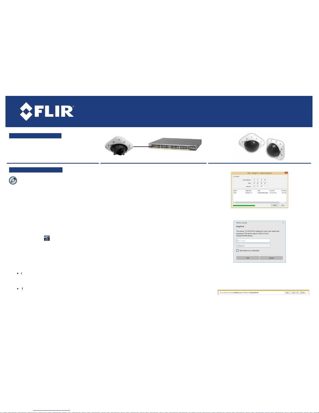
A. Connect the Camera
1. Insert a cable in the RJ45 connector to attach to
the network switch for a 10/100 Mbps Ethernet
and POE+ connection.
B. Discover the Camera
The camera’s web interface can be accessed
by Internet Explorer 10 and higher (32-bit) with the
ActiveX plug-in and by browsers that do not support
ActiveX, such as Microsoft Edge 38 and above,
Chrome v.55 or above, or Firefox v.50 or above, on
PCs running 64-bit Windows 7, 8, 8.1, or 10.
B.1. Configuring the camera on your workstation
for the first time
1. Install the CD in the product package or download
FLIR’s Discovery Network Assistant (DNA) utility from
the Support > Firmware & Software Downloads
page at http://www.flir.com/security.
2. Click the DNA icon and run DNA version 2.1.3.15
or higher to log into the unit.
3. Attach the unit to the same LAN segment as the
computer that is managing the unit. DNA
automatically discovers the unit on the network and
displays the device’s current IP address in the
Discover List.
4. Select the unit from the Discover List.
5. Select PAL or NTSC by selecting the unit.
§
If DHCP is enabled on your network, click
Change Video Format from the context menu or
from the Properties > Device Properties
screen.
§
If DHCP is not enabled, you may need to change
the camera's IP address. See section B.2.b.
6. Click Update.
B.2.a Managing the camera with Horizon, Meridian or on
a DHCP-enabled network
If the camera is managed by Horizon configured as a DHCP
server, or is on a network with a DHCP server, the camera
automatically receives an IP address.
1. Open DNA. The unit is automatically discovered on the
network. See section B.1 for instructions how to install DNA.
2. Verify that the unit is displayed in the Discover List. The unit
status should be displayed as Online and Authenticated.
3. Click Close.
B.2.b Managing the camera with Latitude or on a
network with static IP configuration
If the camera is managed by Latitude or is on a network
without a DHCP server, manually enter its IP address in
DNA.
1. Open DNA. The unit is automatically discovered on the
network. See section B.1 for instructions how to install DNA.
2. If you use non-default credentials, the unit might become
unauthenticated. In this case, authenticate the unit:
a. Use DNA to select the unit(s).
b. Right-click or click the Login button.
c. Enter the camera's User Name ("admin") and Password
("admin").
d. Click Login.
e. Click Close.
3. Right-click Assign IP or click the Assign IP button on the
navigation bar.
4. Uncheck Use DHCP.
5. Enter the unit’s IP, Mask and Gateway IP addresses.
6. Click Update.
7. Click Close.
B.3. Log into the Unit
1. Click the unit in the Discover List. The Login window opens.
2. Enter the default User Name ("admin") and Password
("admin") which are case-sensitive.
3. Click OK.
4. If you are using IE and the Microsoft Visual C++ 2008
Redistributable package is not installed on your PC, on the
camera's Live screen click the link to download it.
5. Click the message to install the ArielPlayer plug-in.
6. Follow the on-screen instructions to install the plug-in.
Page 2
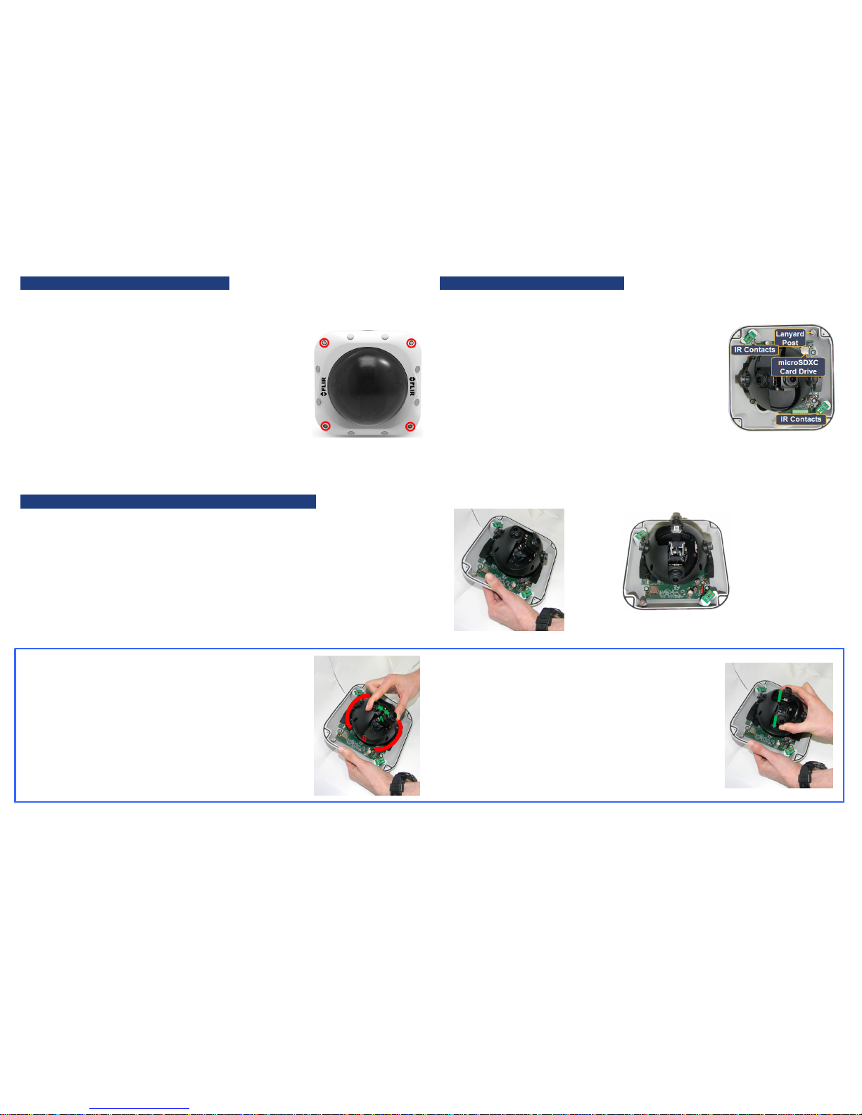
C. Prepare for Camera installation
C1. Using the microSDXC Card
1. Verify that the operating temperature range is between
-40°C ~ 50°C (-40° ~ 122°F), 0-90% relative humidity (noncondensing).
2. Be sure to have the required accessories and tools available.
Refer to the User and Installation Guide.
3. Using the supplied Torx wrench, unscrew the four screws on
the dome cover and remove the cover.
The camera is shipped without a microSDXC card. The card
must be inserted in the camera in order to locally store a
snapshot or recording triggered by an event.
To install a microSDXC card
1. Format a microSDXC card (up to 128GB, Class 10) on your
PC.
2. Insert the card into the drive on the camera’s printed circuit
board.
3. Verify that the card status is displayed as mounted in the unit's
System > Events Handler > SD Card screen.
4. Configure the camera to store snapshots and recordings from
the System > Events Source screens.
C2. Changing the Lens Position from 180° to 360°
The camera is shipped with the lenses mounted for 180° viewing (Wall Mode). The lens
must be physically rotated for the camera to operate in 360° mode (Ceiling Mode).
The illustration below shows how to change the lens orientation
No change is required in the camera's user interface.
Lenses in180 mode
Lenses in 360 Mode
To rotate the lenses
1. Hold the two inner lenses together from the base and rotate
them clockwise. Be sure to leave the protective lens caps on
the lenses during this step.
2. Gently release the lenses until the spring is fully released.
3. Remove the lens caps. The camera reboots in Ceiling Mode
(360° operation).
Page 3

D. Mount and Position the Camera
1. Place the supplied drill template over the installation surface.
2. Drill four holes into the surface.
3. Align the holes on the camera's base plate with the drilled
holes.
4. Screw the base into the installation surface.
5. When mounting the camera in 180° mode, note the position of
the Top Conduit to orientate the camera correctly.
10. Screw the lanyard from the dome cover
onto the lanyard post on the camera base.
See section D.
11. Align the IR contacts on the dome with the
IR contacts on the camera base. See
section D.
12. Replace the dome cover over the base and
screw it closed.
6. Unscrew the cover over the Top or Base cable conduits and
feed the system cables through it.
7. To maximize water protection when using conduit, use the
included rubber O-ring and add teflon tape to the threading.
8. Tighten the screws after all cables are inserted so that the
base plate is flush with the surface.
Note:
The cameras have a circuit protection mechanism that is activated if the cover is removed
while the IR LEDs are on. If the IR LEDs are not operating:
·
Re-attach the cover (making sure that the IR contacts are in place)
·
Make sure that the cover is closed properly
·
Power cycle the camera.
E. Open Live View
1. Select the Live tab.
2. Set the camera view.
9. Insert the leads from the required system cables into their
connectors.
1. RJ45 connector to Category 5 or 6 cable for network
and IEEE 802.3at PoE+ connection.
2. Two-pin terminal block connector for leads to optional
external 24VAC power supply (not provided).
3. 8-pin terminal block connector for leads to alarm and
audio I/Os. (see detail)
4. BNC connector for 75-ohm video cable for analog
audio out in 360° (Ceiling) Mode.
F. Attach to VMS
Once you have completed installation and found the current IP address with DNA, use your
VMS Discovery/Attach procedures to attach the camera to your VMS.
CM-6308_QIG_12Nov17_v.01
FLIR Systems, Inc. 6769 Hollister Ave. Goleta, CA 93117
Tel: +1 888.388-3577 product.enterprise.support@flir.com
www.flir.com/security
 Loading...