

FLIR PTZ-35x140 User Manual
PTZ-35x140 User’s Guide 427-0011-00-10 Version 100
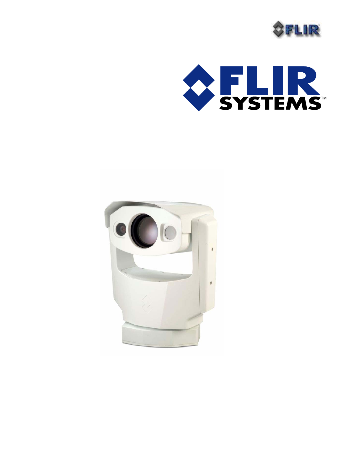
PTZ-35x140™ with Foveus™
Users Guide
427-0011-00-10
Version 100

PTZ-35x140 User’s Guide 427-0011-00-10 Version 100
Cautions and Warnings:
• Do not disassemble the PTZ-35x140™ enclosure. Disassembly can cause permanent
damage and will void the warranty.
• Operating PTZ-35x140™ outside of its specified operating temperature range or voltage
range can cause permanent damage and will void the warranty.
• Avoid pointing the device directly at extremely high-intensity radiation sources, such as the
sun, lasers, arc welders, etc. This warning applies whether or not the system is powered.
• Only clean the lens in the manner prescribed in the Appendix of this document.
• If you have questions that are not covered in this manual, or need service, contact FLIR
Support at 1-888-747-3547 for additional information.

PTZ-35x140 User’s Guide 427-0011-00-10 Version 100
TABLE OF CONTENTS
INTRODUCTION......................................................................................................................... 4
UNPACKING YOUR PTZ-35X140:........................................................................................... 4
QUICK-START INFORMATION.............................................................................................. 5
PELCO-D INTERFACE ....................................................................................................................... 6
NEXUS® CONSOLE INTERFACE .......................................................................................................... 9
PTZ-35X140™ PHYSICAL INTERFACE .............................................................................. 11
IMENSION DRAWINGS.................................................................................................................... 11
D
S
YSTEM INTERFACE CABLE CONNECTOR......................................................................................... 14
BREAK-OUT CONNECTOR CABLE .................................................................................................... 15
PTZ-35X140™ SPECIFICATIONS......................................................................................... 17
APPENDIX A: MAINTENANCE ............................................................................................. 19
LENS CLEANING............................................................................................................................... 19
HISTORY OF INFRARED ....................................................................................................... 20
PTZ-35x140 User’s Guide 427-0011-00-10 Version 100
INTRODUCTION
The PTZ-35x140™ is a versatile, dual field of view thermal and visible imaging system that
provides a high resolution thermal image with a 5° view nested inside a wider 20° view. This image
presentation concept derived from human vision offers excellent situational awareness and long
range threat detection, simultaneously. This advanced payload is packaged in a precision pan/tilt
enclosure that will slew up to 120° per second. The system supports stand-alone or network
operation with a Nexus® interface.
The PTZ-35x140™ incorporates the latest in visible and uncooled thermal imager performance with
both IP networked control and video connectivity for installation into sophisticated emerging
security infrastructures and serial and analog connectivity for current widely proliferated
infrastructures. The Foveus™ thermal imagery is provided as continually zoomed video from 20°
horizontal field of view to less than 1 degree horizontal field of view. The thermal imagery is
presented in a novel blending of two thermal images to provide high resolution in the critical 5°
center area while simultaneously providing medium resolution in the 20° situational awareness zone.
This presentation is an application of the design of the human eye, with the foveal region of the
retina employing higher density detectors than the peripheral area, thus the moniker Foveus™.
UNPACKING YOUR PTZ-35X140:
o PTZ-35x140 with Foveus 427-0011-XX
o Break-Out Connector Cable (1 DB9 RS-422 and 1 DB9 Maintenance for communication, 1
BNC for composite video, 1 RJ45 Ethernet, terminal rings for power) 308-0117-00
o Nexus® Console Software (unlimited copy rights)
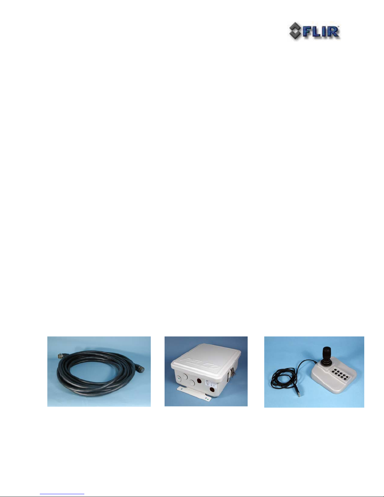
Optional Accessories:
o 40 ft System Cable 308-0116-02 (shown below)
o 24V Power Supply 206-0004-01 (shown below)
o Nexus® Console Joystick 223-0017-00 (shown below)
PTZ-35x140 User’s Guide 427-0011-00-10 Version 100
QUICK-START INFORMATION
The following instructions will get you started with basic operation of the PTZ-35x140™ with
Foveus™.
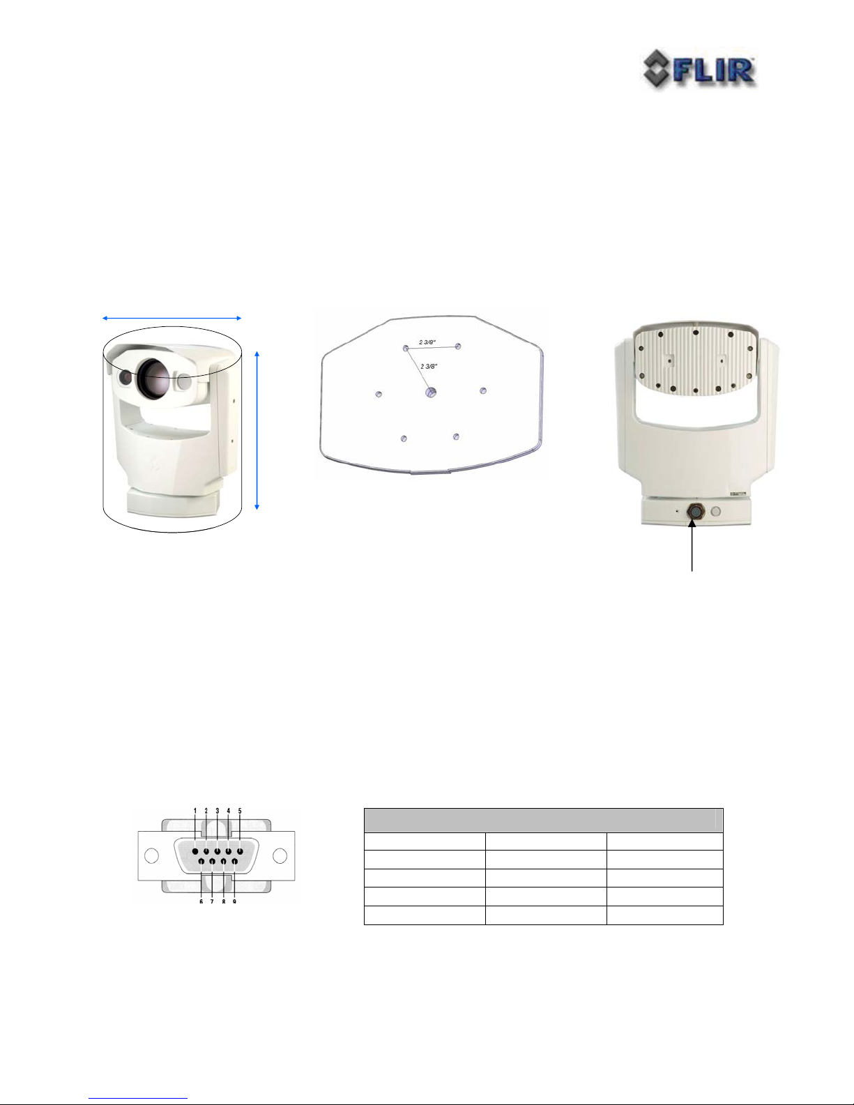
1. Firmly secure camera using mounting pattern shown below to a designated frame or
structure able to support and allow for device travel.
2. Connect System Cable into camera base shown above. Then attach the other end of the
sealed System Cable to the break-out pigtail.
3. If using the video output then plug a standard BNC cable to the connection labeled
“VIDEO P2” on the break-out pigtail.
4. If you intend to use the PELCO-D Interface for remote control of the device attach a
standard DB9 RS-422 cable to the connection labeled “USER P3” on the break-out pigtail.
Connect the other end of the RS-422 cable to an available port on remote control device
such as a KBD300. (Be sure to note that the pin settings are from the camera and must be
swapped on the controller device!) Pin settings are shown here below:
RS-422 DB9 Pin or “USER P3”
COM 1 Tx A (-) Signal OUT Pin 2
COM 1 Rx B (+) Signal IN Pin 3
COM GND Pin 5
COM 1 Tx B (+) Signal OUT Pin 7
COM 1 Rx A (-) Signal IN Pin 8

PTZ-35x140 User’s Guide 427-0011-00-10 Version 100
5. If you intend to use the Nexus® Console Software for both the remote control of the device
and video streaming attach a standard CAT5 cable to the connection labeled “ETHERNET
P5” on the break-out pigtail. Connect the other end to your PC.
6. Plug in either 24+/-10% VAC rms (50/60Hz) or 24+/-10% VDC directly to the connections
labeled “PTPWR” and “SYSPWR” on the break-out pigtail.
7. If purchased the Pelco WCS4-20 Master Power Supply will connect directly via
connections labeled “PTPWR” and “SYSPWR” on the break-out pigtail to the converter.
Connect the black leads to COM and the red leads to 24V. Next, adjust the AC Input
switch to either 115VAC (standard for US) or 230VAC (standard for Europe) and apply
power to the Pelco converter.
8. Now the PTZ-35x140™ is ready for use. Note that the device will immediately zero itself
and return back to home position upon applying power.
PELCO-D INTERFACE
The PTZ-35x140™ accommodates control via RS422. The command protocol for serial control
shall be via PELCO-D commands including the following minimum control set:

PTZ-35x140 User’s Guide 427-0011-00-10 Version 100
Table 1: Pelco D Command List
PTZ-35x140 Function KBD300 Pelco D Packet Pelco D Response
Pan/Tilt Drive Up FF 01 00 08 VV WW CK FF 01 00 CK
Down FF 01 00 10 VV WW CK FF 01 00 CK
Left FF 01 00 04 VV WW CK FF 01 00 CK
Right FF 01 00 02 VV WW CK FF 01 00 CK
UpLeft FF 01 00 0C VV WW CK FF 01 00 CK
UpRight FF 01 00 0A VV WW CK FF 01 00 CK
DownLeft FF 01 00 14 VV WW CK FF 01 00 CK
DownRight FF 01 00 12 VV WW CK FF 01 00 CK
Stop FF 01 00 00 VV WW CK FF 01 00 CK
Increments Focus closer Near button FF 01 01 00 00 00 02 FF 01 00 02
Increments Focus farther Far button FF 01 00 80 00 00 81 FF 01 00 81
Zoom In or Decreases FoV CW Joystick FF 01 00 20 00 00 21 FF 01 00 21
Zoom Out or Increases FoV CCW Joystick FF 01 00 40 00 00 41 FF 01 00 41
IR Polarity to Black Hot 1, Aux On FF 01 00 09 00 01 0B FF 01 00 0B
IR Polarity to White Hot 1, Aux Off FF 01 00 0B 00 01 0D FF 01 00 0D
Active Camera DLTV 2, Aux On FF 01 00 09 00 02 0C FF 01 00 0C
Active Camera IR 2, Aux Off FF 01 00 0B 00 02 0E FF 01 00 0E
Toggle: Plateau Values 3, Aux On FF 01 00 09 00 03 0D FF 01 00 0D
Toggle: AGC Type 3, Aux Off FF 01 00 0B 00 03 0F FF 01 00 0F
AutoFocus 4, Aux On FF 01 00 09 00 04 0E FF 01 00 0E
IR FFC 4, Aux Off FF 01 00 0B 00 04 10 FF 01 00 10
Toggle: LUT Palette 5, Aux Off FF 01 00 0B 00 05 11 FF 01 00 11
Toggle: AGC ROI 6, Aux On FF 01 00 09 00 06 10 FF 01 00 10
Toggle: Max Gain Value 7, Aux Off FF 01 00 0B 00 07 11 FF 01 00 11
Also, refer to the User Controls for use with a Pelco KBD300A shown on the following page:
 Loading...