

Page 1

M-Series
432-0003-00-10
Revision 140
January 2011
Operator’s Manual
Page 2

© FLIR Systems, Inc., 2010. All rights reserved worldwide. No parts of this manual, in whole
or in part, may be copied, photocopied, translated, or transmitted to any electronic medium or
machine readable form without the prior written permission of FLIR Systems, Inc.
Names and marks appearing on the products herein are either registered trademarks or
trademarks of FLIR Systems, Inc. and/or its subsidiaries. All other trademarks, trade names,
or company names referenced herein are used for identification only and are the property of
their respective owners.
This product is protected by patents, design patents, patents pending, or design patents
pending.
The M-Series thermal imaging system is controlled by US export laws. There are special
versions of this system that are approved for international distribution and travel. Please
contact FLIR Systems if you have any questions.
FLIR Systems, Inc.
70 Castilian Drive
Goleta, CA 93117
Phone: +1.888.747.FLIR (+1.888.747.3547)
www.flir.com/maritime
Document Number: 432-0003-00-10, Version 140
Document History
Revision Date Comment
100 June 2009 Initial Release
110 February 2010 Release of M-320L and M-324XP and minor changes
120 March 2010 Minor corrections and clarifications
130 December 2010 Release of M-625XP, M-324L and M-625L
Replacement of M-320L and M-626L
140 January 2011 Minor corrections
This document is controlled to FLIR Technology Level 1. The information contained in this
document pertains to a dual use product controlled for export by the Export Administration
Regulations (EAR). FLIR trade secrets contained herein are subject to disclosure restrictions as
a matter of law. Diversion contrary to US law is prohibited. US Department of Commerce
authorization is not required prior to export or transfer to foreign persons or parties unless
otherwise prohibited.
Page 3

Contents
Warnings and Cautions ......................................................... 10
System Description............................................................... 11
Camera Video Options ......................................................... 12
Multiple Camera and JCU Options......................................... 13
JCU Introduction .................................................................. 13
Video Display ....................................................................... 15
Video Screen Icons ............................................................. 16
SCENE Icons ..................................................................... 17
System Startup.................................................................... 19
The Bootup Process ............................................................ 19
M-Series Video ................................................................... 23
JCU Power Menu ................................................................. 24
Accessing the Power Menu .................................................. 24
Factory Default Settings........................................................ 26
System Operation and Configuration ....................................... 27
Operation/Configuration Using JCU Buttons ............................ 28
Configuration Menus............................................................. 30
Video Setup Menu............................................................... 31
Set Symbology.................................................................... 33
User Programmable Button ................................................. 34
System Setup..................................................................... 35
About/Help........................................................................ 40
System Reset Functions ........................................................ 42
JCU Reset ......................................................................... 42
Camera Reset .................................................................... 42
Operation Tips...................................................................... 43
Troubleshooting Tips ............................................................. 44
On Screen Messages .......................................................... 47
Restoring the Factory Network Settings ................................ 48
M-Series IP Interface and PC Operations ................................. 49
M-Series Web Control ......................................................... 50
Web Control Functions ........................................................ 51
UPnP Configuration............................................................. 55
Network Settings ................................................................. 58
432-0003-00-10 rev 140 M-Series Operator’s Manual 5
Page 4

Custom Network Applications ................................................ 61
432-0003-00-10 rev 140 M-Series Operator’s Manual 6
Page 5

Glossary
Acronym/Term Definition
AGC Automatic Gain Control
ANSI American National Standards Institute
API Application Programming Interface
EAR Export Administration Regulations
EMI Electromagnetic Interference
FFC Flat Field Correction
FLIR
Forward Looking Infrared
ICD Interface Control Document
IEC
International Electrotechnical Commission
IEEE Institute of Electrical and Electronics Engineers
IR Infrared
JCU Joystick Control Unit
NMEA National Marine Electronics Association
P/T Pan/Tilt
PoE Power Over Ethernet
SCTE Society of Cable Telecommunications Engineers
SDK Software Developer’s Kit
VDC Volts, Direct Current
VIS Visible
7 432-0003-00-10 rev 140 M-Series Operator’s Manual
Page 6

8 432-0003-00-10 rev 140 M-Series Operator’s Manual
Page 7
CHAPTER 1 M-Series System
Description
Thank you for buying your new M-Series thermal imaging system. This manual describes the operation of the M-Series camera. If you need help or have
additional questions, please call to speak with our support experts (phone
numbers listed on the back cover of this manual).
This manual includes information about the following topics:
• System Description
• System Startup
• Configuration Menus
• Operation Tips
Refer to the M-Series Installation Guide (FLIR Doc. # 432-0003-00-12) for
information about how to install the camera.
432-0003-00-10 rev 140 M-Series Operator’s Manual 9
Page 8
Warnings and Cautions
For safety, and to achieve the highest levels of performance from the
M-Series system, always follow the warnings and cautions in this manual
when handling and operating the M-Series camera system.
Warning: Warning notices are used in this publication to emphasize that
hazardous voltages, currents, temperatures, or other conditions that could
cause personal injury or death exist with this equipment, or may be associated with its use.
Caution: Caution notices are used where equipment might be damaged if
care is not taken.
Note: Notes call attention to information that is especially significant to
understanding and operating the equipment
Warnings and Cautions
Warning: Do not use the M-Series imaging system as the primary naviga-
tion system. Use it in conjunction with other navigation aids and a primary
manual navigation system.
Warning: Use of insufficient wire gauge can result in fire.
Caution: Do not open the M-Series camera unit for any reason. Disassem-
bly of the camera (including removal of the cover) can cause permanent
damage and will void the warranty.
Caution: Be careful not to leave fingerprints on the M-Series’s camera
optics.
Caution: The M-Series requires a power supply of 12 - 24V DC nominal, 5
Amp maximum. Absolute voltage range: 10 - 32V DC. Operating the camera outside of the specified input voltage range or the specified operating
temperature range can cause permanent damage.
Note: The M-Series IR Thermal Imaging System is an Export Controlled
item. Authorization by the U.S. Government must be obtained prior to
export outside the United States.
This equipment must be disposed of as electronic waste. Contact your
nearest FLIR representative for instructions on how to return the product
to FLIR for proper disposal.
10 432-0003-00-10 rev 140 M-Series Operator’s Manual
Page 9
System Description
Thermal Image at night
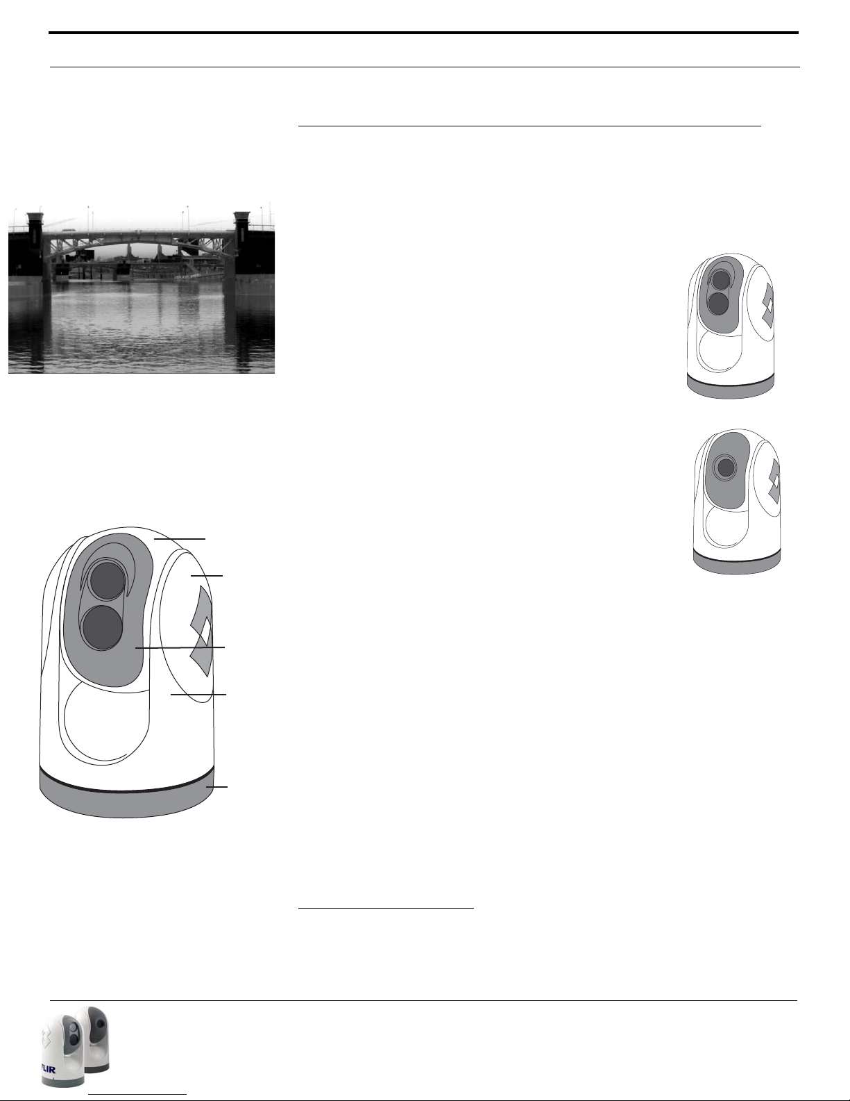
Dual Payload
Single Payload
Base
Ball
Side
Cover
Bezel
Yoke
Gimbal Assembly
System Description
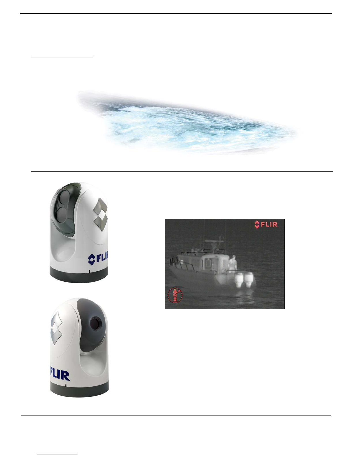
M-Series is a maritime thermal imaging system for use on nearly any kind of
vessel. The system is available in two configurations: the single payload
model has a single thermal imaging camera, and the dual payload model is
equipped with both a thermal imaging camera and a visible-light camera.
The infrared (IR) thermal camera provides night-time
imagery, even in total darkness, based on temperature
differences. The thermal camera provides a clear video
image even under completely dark conditions because it
is sensitive to thermal infrared energy.
On dual payload models, the integrated visible-light camera provides black and white (or greyscale) imagery during the day and in low-light conditions. It provides
enhanced navigational abilities in lowlight conditions; for
example, during twilight hours, when operating along
intercoastal waterways, and near harbor entrances.
The M-Series consists of two main components: the
Gimbal Assembly
1
(also known as the pan/tilt camera
unit) and the Joystick Control Unit (JCU). In this manual,
the term “camera” may refer to the entire camera unit/
gimbal assembly, or it may refer specifically to either the
thermal camera or the visible camera, depending on the
context in which it is used.
The M-Series gimbal and JCU are network devices and
connect together with Ethernet. In some installations, additional cameras
and JCUs will also be used, and networking equipment such as Power Over
Ethernet switches may be used to interconnect these components.
M-Series Gimbal Assembly
The Gimbal Assembly has a pan/tilt mechanism that allows the camera to
rotate continuously 360° in azimuth, and to tilt plus or minus 90° in elevation. The M-Series imaging sensors are contained in the ball of the Gimbal
Assembly.
The thermal infrared camera uses an uncooled vanadium oxide (VOx) detector sensitive to long-wave infrared (LWIR) thermal energy. The camera is
sensitive to the thermal energy that comes from the movement of atoms
and molecules that make up whatever the camera is pointed at. All objects
emit (or radiate) this thermal energy, even cold objects like icebergs.
1 A gimbal is a pivoted support that allows the rotation of an object (such as a ship’s
compass) about a single axis.
432-0003-00-10 rev 140 M-Series Operator’s Manual 11
Page 10
System Description
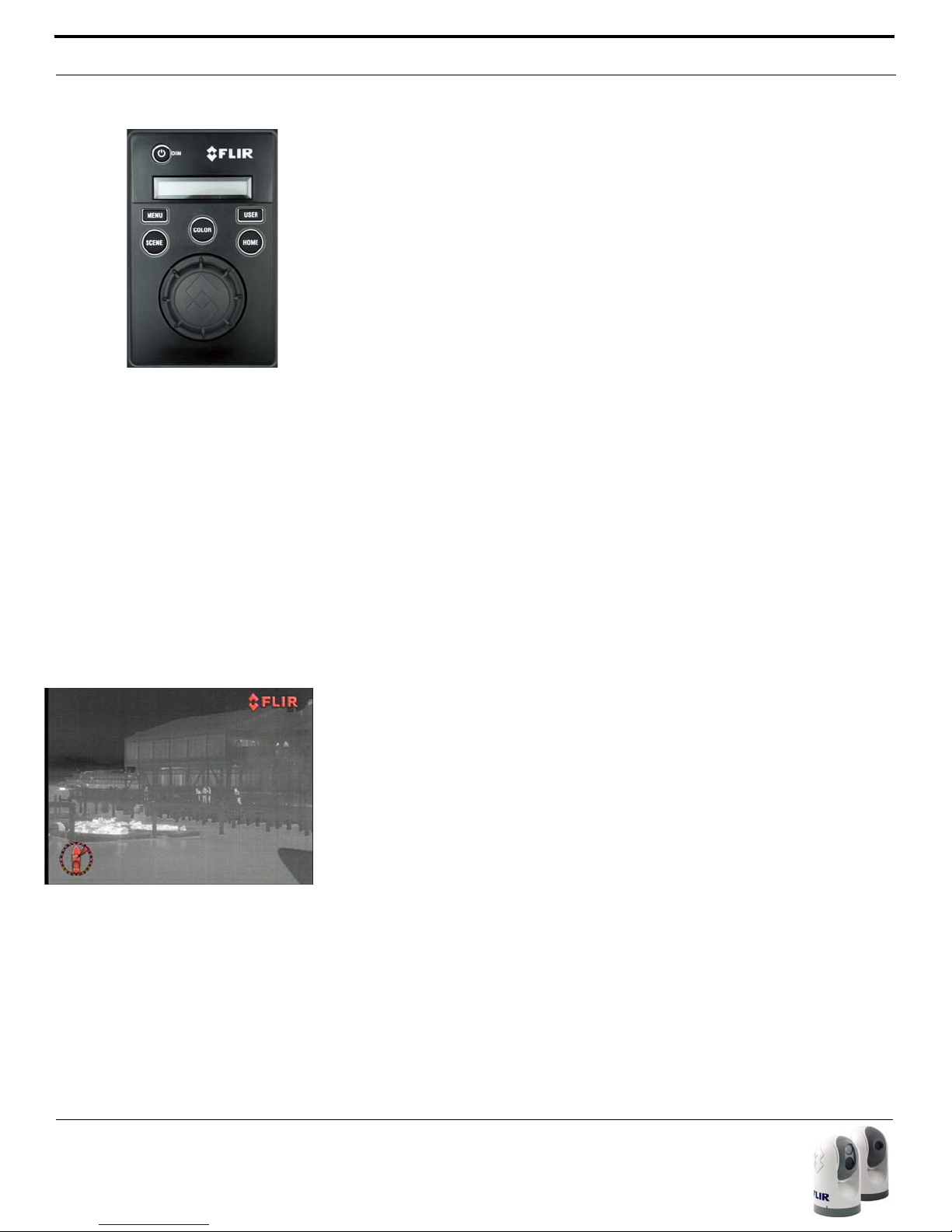
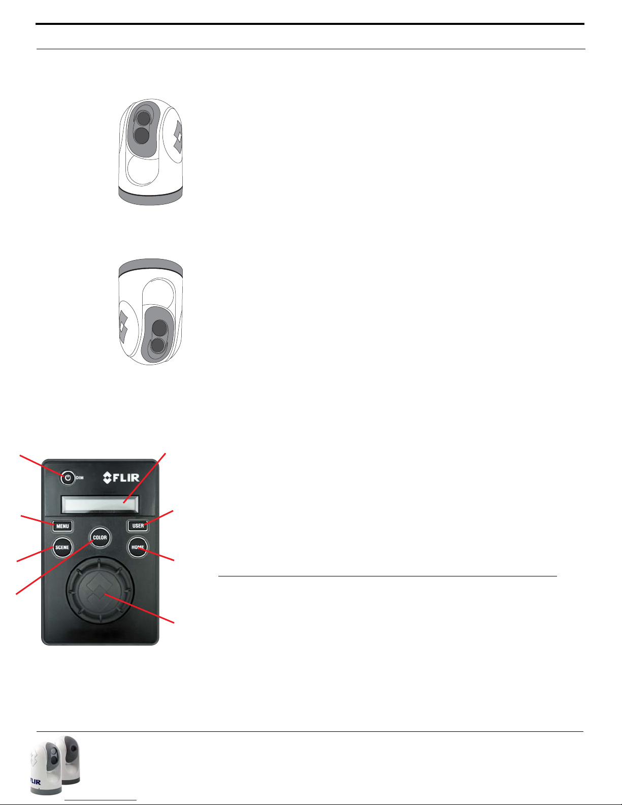
Joystick Control Unit (JCU)
The JCU is used to power up the camera or put it in a standby state, to
operate the pan (rotation) and tilt movement of the camera, and to configure the camera settings by means of on-screen menus. The JCU connects
to the camera by way of an Ethernet network connection, and that same
connection provides power to the JCU.
The JCU has various buttons, an LCD display, and it has a joystick “puck”
which is used to control the pan/tilt movement and to navigate through the
on-screen menus. The puck can be rotated in either direction and it can be
moved left and right or forward and back, and it can be pushed down (like a
button) and pulled up.
Joystick Control Unit
Other Components
In some installations, the system will be comprised of additional components, including additional cameras or JCUs, video equipment, or network
equipment. In a simple installation, the JCU will be directly connected to the
camera with an Ethernet cable. In more complex installations, the camera
and JCU will be interconnected by means of a network switch. If the network switch does not have Power over Ethernet (PoE) capability, a PoE injector may be used to provide power to the JCU. FLIR PoE injectors are
available where you purchased your M-Series camera.
Contact FLIR (+1.888.747.3547 or +33 765794194) for more information regarding available accessories including JCUs, PoE equipment, video
distribution amplifiers, cables, connectors, mounting hardware, and so on.
Camera Video Options
The M-Series camera provides a video cable (labeled “IR”) for the composite
(also known as analog) video signal from the thermal (infrared) camera. On
dual payload models, another video cable (labeled “VIS/IR”) is for video from
either the thermal camera or the lowlight (visible) camera; it is switchable
from the JCU.
12 432-0003-00-10 rev 140 M-Series Operator’s Manual
The video from the dual payload M-Series camera can therefore be displayed on one or two video displays. If only a single display with a single
video input is available, the cable labeled “VIS/IR” is connected to the display. If the display has more than one video input, both video cables can be
connected to the same display. In this type of installation, switching
between the thermal and visible video channels is performed with the display controls, rather than the JCU.
Page 11
JCU Introduction
Upright installation
(ball up)
Upside down
(ball down)
Joystick Control Unit
Puck
Power/DIM Display
Home
Scene
User
Menu
Color
Ball Up / Ball Down
In most installations, the M-Series will be mounted upright on top of a
mounting surface, with the pan/tilt base below the camera (this is known as
the “ball up” orientation). Optionally the unit may be hung upside down (“ball
down”). When installed ball down, it is necessary to configure the camera in
the ball down mode, so the video is properly displayed and the pan/tilt controls operate as expected (information about how to configure the camera is
available in the System Operation and Configuration section).
Unless otherwise noted, the information in this manual generally assumes
an upright installation; refer to the Configuration Menus section for information about ball down configurations.
Multiple Camera and JCU Options
More than one JCU can be used to control the camera, and more than one
display can be used to view the video. Also a single JCU can be used to control more than one camera.
Most often, the JCU and the video monitor are mounted close together, as
a pair, so the video can be viewed when the camera position (pan or tilt) is
changed with the JCU.
The JCU can be connected to the camera directly with the supplied doubleshielded Ethernet cable. In this case, the JCU draws its power from the
camera. Alternatively, the camera and the JCU can be connected together
via an Ethernet switch; this type of configuration allows more than one camera and/or JCU to be used. The JCU draws its power over the Ethernet, so
a PoE injector or PoE switch is required.
If a single JCU is used to control more than one camera, the user can
select which camera is to be controlled through a menu on the JCU. In the
LCD display of the JCU, the name of the currently selected camera is displayed. When more than one JCU is installed in the system, a camera can
respond to commands from any JCU that is in the system.
JCU Introduction
The JCU is the primary method of control for the M-Series camera. It can
be used to move the camera (pan or tilt), electronically zoom the cameras in
and out, switch between infrared and visible-light cameras, adjust the image
quality, and access the on-screen menus.
432-0003-00-10 rev 140 M-Series Operator’s Manual 13
Page 12
JCU Introduction
This section contains a brief description of the buttons and other features
on the JCU. More detailed descriptions of the buttons and their functions
are provided in the subsequent sections of this manual.
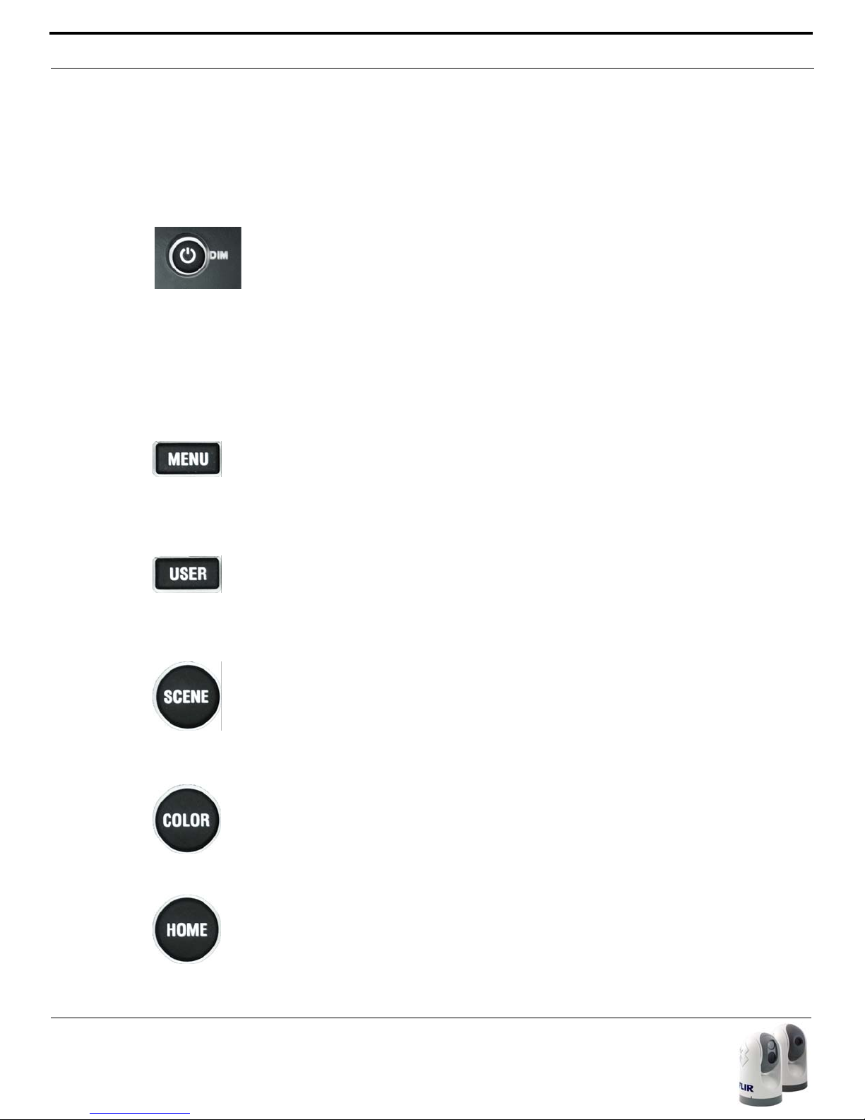
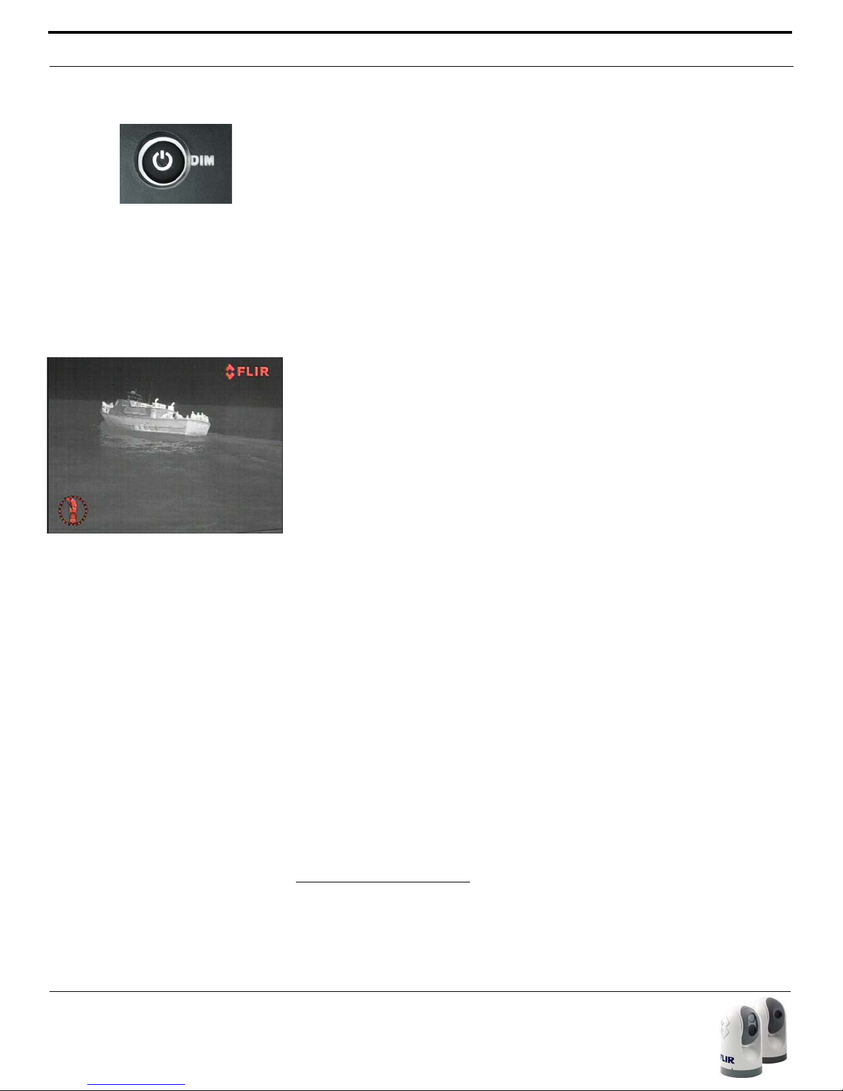
Power/DIM
The Power button is used to “wake up” the camera, causing it to go from
Standby mode to Powered On. It is also used to put the camera back in
Standby mode. The Power button is described in more detail in the System
Startup section.
The Power button is also used to select various levels of brightness of the
JCU display. The JCU controls are backlit to make them easier to see at
night. This button controls the brightness of the JCU backlighting, so you
can adjust it for your comfort. Press this button to cycle through the four
different settings or levels of brightness.
MENU
The MENU button is used to turn on or off the on-screen menu. When the
on-screen menu is displayed, the joystick puck can be used to navigate
through the menus and select various menu entries. The on-screen menus
are described in the Configuration Menus section.
USER
The USER button is a programmable one-touch button. It is intended to
allow the user to quickly access the most common or favorite settings or
functions. It is configured with the Invert Video Polarity setting by default.
SCENE
The SCENE button allows the user to toggle through a set of preconfigured
image settings, in order to select the best setting for the given conditions.
Refer to the Operation/Configuration Using JCU Buttons section for more
details about how to use the SCENE button to optimize the video.
COLOR
The COLOR button switches the thermal camera video between a greyscale
mode and a color mode. When viewed at night in the darkness, the factory
default mode uses a red-colored video image that may preserve the user’s
night vision better. The default color setting is selectable by the user.
HOME
The HOME button is used to move the camera to its home position, or it is
used to select a given position as the home position. The Home position is a
14 432-0003-00-10 rev 140 M-Series Operator’s Manual
Page 13
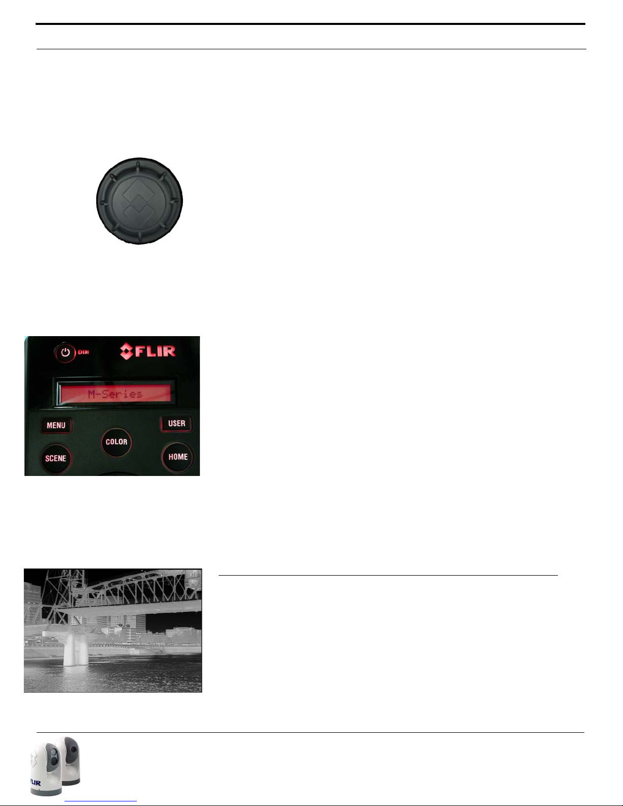
Video Display
JCU powered on with backlit
display and buttons
programmable preset position - usually straight ahead and level with the
horizon – which operators can use as a reference.
JCU Puck
The JCU Puck functions like a joystick - it can be moved left or right, or fore
and aft, and it can be rotated in either direction. It can also be pushed down
(like a mouse click) or pulled up. It is used to move the pan/tilt position of
the camera and it is used to navigate through the on-screen menus.
Use the Puck to pivot the M-Series camera left and right and tilt it up and
down.
Pan - Rotate (twist) the puck counterclockwise and the M-Series will pivot
left. Rotate the Puck clockwise and the M-Series will pivot to the right.
Tilt - Push the Puck forward (toward the bow) and the camera will tilt down;
pull it back (toward aft) and the camera will tilt up.
Zoom - Push down for 1 second to turn on 2X electronic zoom on the IR
camera. Push and hold for 2 seconds for 4x zoom (M-6xx models only). Pull
up on the Puck to return to 2X zoom and pull again to return to no zoom.
The lowlight visible camera does not have a zoom feature.
Freeze - To momentarily pause the IR video and freeze the current image on
the screen, double click (press down twice quickly). Any any other action
with the JCU (moving the puck or pushing a button) will unfreeze the image.
The Puck implements proportional control; therefore the father you rotate it
or direct it from center; the faster the camera will move.
JCU Display
The JCU Display generally shows the name of the camera that the JCU is
“connected” to. It also shows various JCU status messages, and it shows
the countdown (3, 2, 1, 0) to access the Power Menu when the power
button is pressed and held.
Video Display
The M-Series thermal imager does not produce an image from visible light
like an ordinary camera does; rather, it uses thermal infrared energy to produce an image. It senses subtle differences in temperature and makes
images based on those differences.
When the thermal camera is in white-hot mode, the warm things in the
scene will display as white, or lighter shades of grey, and cold objects will
432-0003-00-10 rev 140 M-Series Operator’s Manual 15
Page 14
Video Display
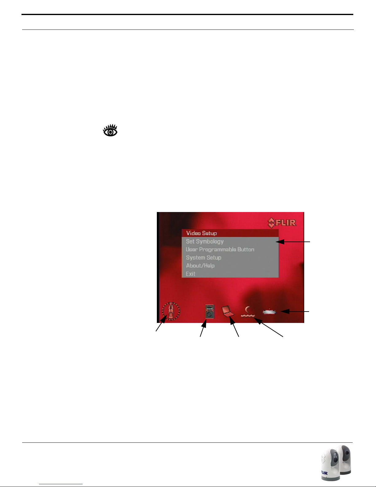
On-screen
Menu
Position
Indication
JCU Icon
Rearview
Icon
PC Icon SCENE Icon
display as black or darker shades of gray. (When you switch the video polarity, this will be reversed.)
Video Screen Icons
The following section provides a brief description of the symbols that may
appear on the screen, depending on the camera settings and the JCU buttons that have been pushed.
Note: Symbology and menu functions are only available in the thermal
image.
Some icons are on the screen all the time, and some icons appear momentarily or only when certain functions are enabled. Several configuration settings are available to control which icons appear or do not appear. Refer to
the System Operation and Configuration section for a detailed description of
each setting and the on-screen menus.
The figure below shows an example of a screen with some of the possible
icons displayed, as well as the on-screen menu.
16 432-0003-00-10 rev 140 M-Series Operator’s Manual
On-Screen Menu
The on-screen menu appears when the MENU button is pressed. Menu
entries are selected using the joystick puck. Pressing the MENU button
again removes the menu from the screen.
Page 15
Video Display
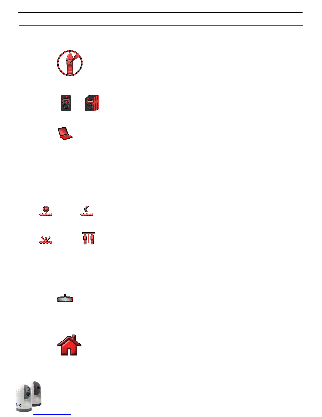
Day Running
Man Overboard
Night Running
Night Docking
Position Indication
The Azimuth Indication shows the azimuth (or direction) of the camera relative to the vessel. The shaded triangle shows the approximate camera field
of view (FOV).
JCU Icon
A single JCU Icon indicates only one JCU is currently connected to the camera unit. If more than one JCU is discovered, the multiple JCU icon will
appear on screen.
PC Icon
The PC Icon indicates there is a PC on the network that has a connection
with the camera. FLIR offers a Software Developer’s Kit (SDK) that allows
marine electronics integrators to develop custom software applications for
networking the M-Series thermal camera and other marine electronics.
Contact your FLIR dealer where you purchased the camera for additional
information, or contact FLIR directly: +1.888.747.3547 or +33
765794194.
SCENE Icons
Pressing the SCENE button toggles between four preset Automatic Gain
Control (AGC) settings. Toggling between the four presets will change the
image gain and level settings. Regardless of the SCENE setting, the thermal
camera automatically adjusts to the scene to provide a balanced, high-quality image. However, you may prefer an image that has more or less contrast
than the default one provided, and the SCENE button provides that type of
fine adjustment.
Which setting to use comes down to personal preference and environmental conditions – you may like the way the Man Overboard setting looks, even
though you are running on open water during the daytime.
Rearview Icon
The Rearview Icon indicates the Rearview Mode option has been selected in
the System Settings menu. The Rearview setting flips the video image horizontally left to right. The image on the display provides the same perspective
as a rear view mirror in a vehicle - objects off the stern on the starboard
side of the vessel are displayed on the right hand side of the video.
Home Icon
The Home icon appears momentarily to indicate the camera is in the Home
position. The icon flashes when a new home position is set.
432-0003-00-10 rev 140 M-Series Operator’s Manual 17
Page 16
Video Display
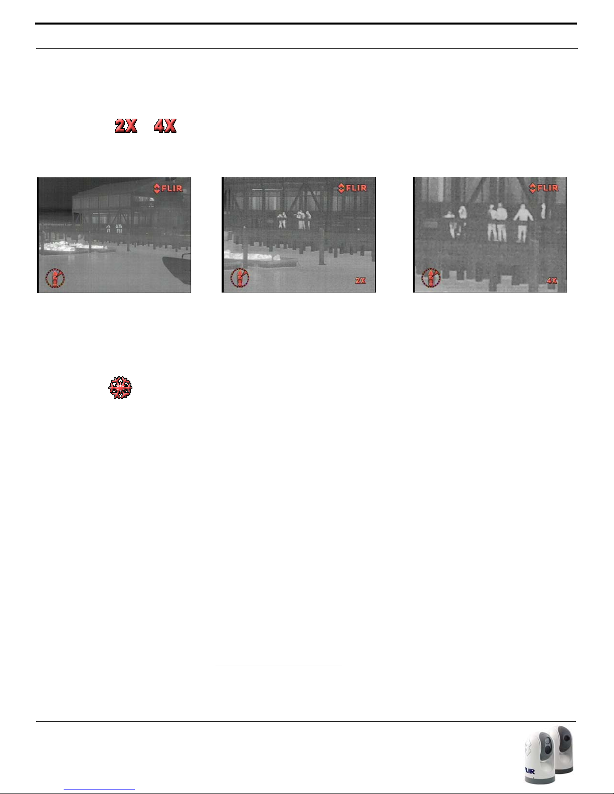
Zoom (2X or 4X2)
Pressing and holding the Puck will cause the thermal camera to digitally
zoom in to 2X magnification. Pressing and holding again will cause the thermal camera to digitally zoom in to 4x magnification (M-6xx models only). Pull
and hold the puck to zoom out the thermal camera.
Normal (no zoom)
2X zoom
4X zoom
Image Frozen
The Image Frozen image appears when the Puck has been double clicked
(pressed two times in quick succession) and the video has been momentarily stopped. Pressing any button or moving the Puck will switch back to
live video. This feature is only available on the thermal camera.
18 432-0003-00-10 rev 140 M-Series Operator’s Manual
2 Note, 4X Zoom not available on all models.
Page 17

CHAPTER 2 M-Series System Startup
System Startup
In order for the M-Series camera to operate, it will need to receive a "wake"
command from another device on the LAN network. This section describes
the system startup process and various camera modes.
To begin, turn on the video monitor/display and select the M-Series thermal
camera as the video source for the display. Most multi-function displays
(MFDs) allow the user to select from a number of available inputs.
Generally the M-Series system will be connected to its power source
through a circuit breaker, which will function as the primary “on/off” switch
for the system. There is no on/off switch on the camera itself, but the JCU
has an power switch, and it is used to control the state of the camera.
If the camera has power, it will be in one of three states or modes: Bootup,
Standby, and Powered On. The camera is never off unless the circuit
breaker is off. When the JCU power button is used to “turn off” the system,
the camera goes into a low-power standby mode waiting for a wake command.
The Bootup Process
When power from the circuit breaker is initially applied to the system, the
camera will perform a short pan/tilt initialization by rotating back and forth
and tilting up and down, and the camera will begin a bootup sequence.
When the JCU receives power, an amber light on the Power/DIM button will
come on. When the Power/DIM button is pressed, the JCU will search for
M-Series cameras on the network.
432-0003-00-10 rev 140 M-Series Operator’s Manual 19
Page 18
System Startup
Troubleshooting Tip: if the JCU does not have power, it may be connected
to a Power over Ethernet (PoE) switch which has not been powered on, or it
may be connected to a network switch that does not provide PoE power.
Bootup Mode
The following section describes what happens when the circuit breaker is
energized and power is applied to the camera. The camera will stay in the
Bootup state for approximately 55 seconds. During the bootup process,
the bootup screen and messages are displayed on the monitor, followed by
live video, which is displayed only momentarily, until the camera goes into
standyby mode..
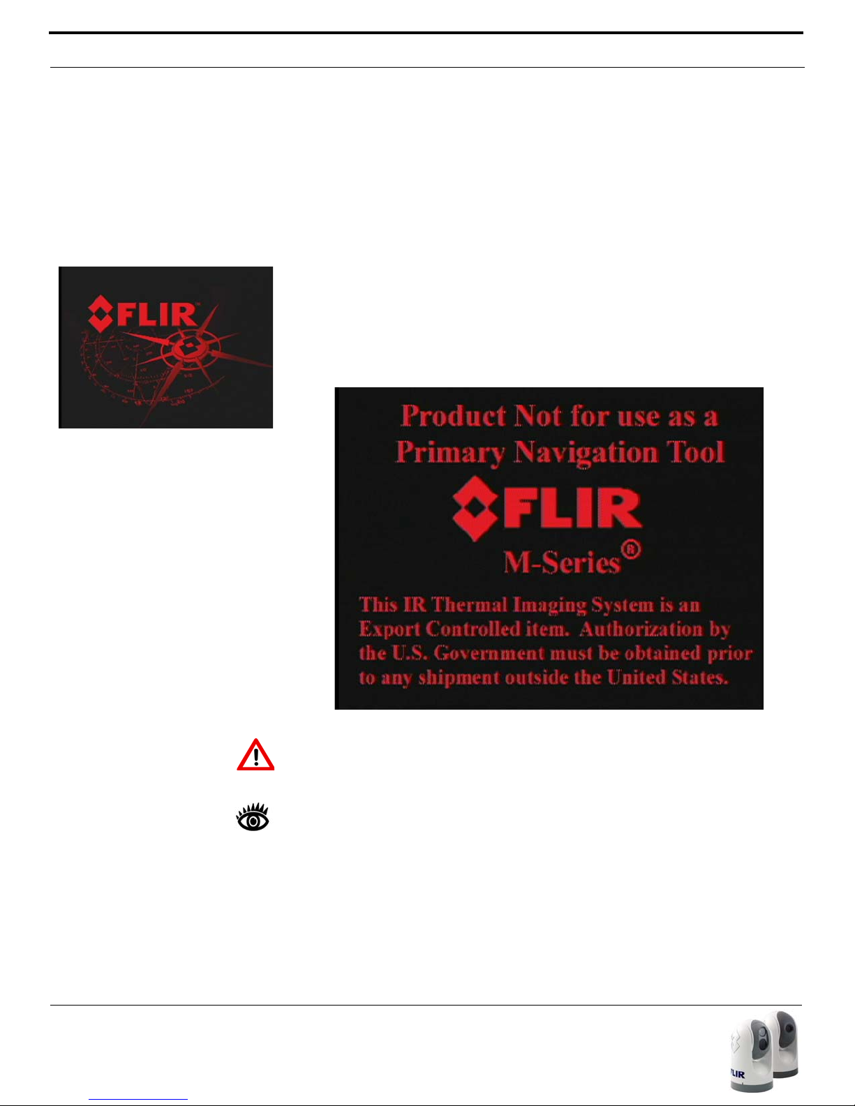
Initially the FLIR splash screen will appear, as shown to the left. Then
another splash screen with two important notices will appear:
20 432-0003-00-10 rev 140 M-Series Operator’s Manual
Warning: Do not use the M-Series imaging system as the primary navigation system. Use it in conjunction with a primary navigation system and
other navigation aids.
Note: The M-Series IR Thermal Imaging System is an Export Controlled
item. Authorization by the U.S. Government must be obtained prior to
export outside the United States.
After the splash screens are displayed, the video screen will show a message that says “Loading, please wait...”
1
When the bootup is complete, the monitor will briefly show live video, and then the display will be
blank, to indicate the camera is in Standby mode. The gimbal assembly
Page 19

System Startup
moves to the Stow position in order to provide additional protection for the
camera optics.
Camera Discovery
If the Power/Dim button is pressed after the system bootup is complete,
the JCU will automatically detect all available cameras on the network. The
first time a camera is started, the installer must associate the JCU with the
camera. The display on the JCU will indicate “Select Camera” the first time
a JCU connects to a camera. Scroll down to the available camera and press
(or “click") the puck to accept the camera shown in the JCU Display. The
JCU will automatically connect to the last camera it was linked to after the
initial startup.
Troubleshooting Tip: if the JCU does not discover any cameras, check to
make sure the JCU and the camera are connected to each other over the
network or directly with a single cable.
If the Power/Dim button is pressed while the camera is booting up, the JCU
LCD display will say "Searching..." until the JCU discovers cameras on the
network. If there are multiple cameras in the network, the JCU will discover
them and the user must select one. The user can move the puck fore and
aft to scroll through the list of discovered cameras. Once a camera has
been selected, the next time the user powers the JCU, the JCU will default
to the last camera it was connected to.
Note: When a dual payload
camera powers up, it will display
the IR video on both channels
initially. Then the IR/VIS video
channel will switch to the visible
camera if the visible camera
was selected when the camera
was last powered down.
Note: In the JCU Display, a down arrow (V) indicates additional menu
choices can be accessed by moving the puck down (aft), or by rotating the
puck clockwise. An up arrow (^) indicates the last menu entry is shown in
the display, and the other choices must be accessed by moving the puck up
(fore) or by rotating the puck counterclockwise. A double arrow indicates the
user can move up or down in the menu.
Standby Mode
After the bootup sequence, the camera will switch from the Bootup mode to
the Standby mode. In the Standby mode the pan/tilt motors are engaged in
high-power mode, to hold the camera in place in rough seas. In the Standby
mode, the cameras will not supply a live video signal via the video cables.
The gimbal assembly does not respond to any commands or buttons from
the JCU (with the exception of the Power/DIM button). The camera ball will
be pointing straight down, to protect the camera optics.
1 Refer to the Troubleshooting Tips section in the System Operation and Configura-
tion chapter for more information about messages that appear on the video
screen.
432-0003-00-10 rev 140 M-Series Operator’s Manual 21
Page 20
System Startup
Note: Selecting “Camera Stndby?”,
“System Stndby?” or “Global
Stndby?” on the JCU will not shut
down the camera entirely. The camera will go into the Standby mode,
with the motors engaged, waiting for
a “wake” command from the JCU.
Powering Up
To power up the camera, press and hold the Power/DIM button on the
JCU for 3 seconds. The camera will switch from the Standby state to the
Powered On state. Once the M-Series gimbal assembly is in the Powered
On mode, the cameras will display the two splash screens and then supply
live video to the monitor. The camera will rotate to the home position and
the ball will tilt up to its home position and the JCU icon will appear on the
screen momentarily. On the JCU display, the camera name will blink
momentarily to indicate the camera is selected. The camera will now
respond to the JCU buttons and joystick puck movements.
Powering Down
When the camera is in the Powered On mode, pressing the Power/Dim
button continuously for 2 seconds will cause the display to start a brief
countdown (3, 2, 1, 0). After the countdown the JCU will enter the JCU
Power Menu
2
, and the display will show “v Power Menu”. The JCU puck
can be used to select from the following menu options:
Power Menu
Assign JCU
JCU Stndby?
Camera Stndby?
System Stndby?
Global Stndby?
3
Calibrate JCU
Cancel
Each of these menu items are described in more detail in the JCU Power
Menu section below.
If the “Camera Stndby?”, “System Stndby?” or “Global Stndby?” option
is selected, the camera will move to the stowed (parked) position and the
camera will go into the Standby state. Generally the stowed position is with
the ball rotated down so the camera lenses are in a protected position. The
Stow position can be configured with the on-screen configuration menus.
If the camera will not be used for an extended period of time and it is preferable to conserve power, it is recommended that you first power down the
camera from the JCU as described above. Powering the camera down
from the JCU will put the camera in the Stow position. Then switch the system circuit breaker to the off position. When the circuit breaker is switched
on again, the camera will go through its bootup sequence again.
22 432-0003-00-10 rev 140 M-Series Operator’s Manual
2 Refer to the JCU Power Menu section for a detailed description of the JCU
Power Menu.
3 Global Stndby will only be shown when multiple JCU's have been detected.
Page 21

System Startup
Red-hot Mode
White-hot Mode
M-Series Video
The M-Series thermal camera starts up in “red-hot” mode by default. Many
users will be turning the system on when there is little or no light available,
and the red-hot mode will help preserve the operator’s night vision. If the
white-hot display mode is preferred, simply press the COLOR button on the
JCU. Through the configuration menus, it is also possible to save a default
color setting to be used each time the system is powered on.
Now that the system has started up, hopefully you will be able to put it to
use right away. It is recommended that you become familiar with the system, especially the JCU buttons and operation of the puck, while the vessel
is stationary. You should begin using the SCENE, COLOR, and USER buttons
and get familiar with how they affect the displayed video.
432-0003-00-10 rev 140 M-Series Operator’s Manual 23
Page 22

JCU Power Menu
JCU Power Menu
The JCU is a bit more sophisticated than most joystick devices; in fact it
has its own microprocessor and is capable of communicating with other IP
devices on a network. To aid in the control of the system, the JCU has an
LCD display that shows JCU messages, menu options, and general status
information. The various JCU functions can be accessed via a set of
menus, with each menu entry selectable in the JCU display.
The JCU puck is used to scroll up and down within the menus, and a menu
entry can be selected by pressing down (clicking) the puck. When the JCU
is in the Power Menu mode, the other JCU buttons such as HOME, COLOR,
SCENE, and USER are disabled.
Accessing the Power Menu
When the camera is in the Powered On mode, pressing and holding the
Power/DIM will cause the JCU to enter the JCU Power Menu and the display will show “v Power Menu”.
The JCU puck can be used to select from the following menu options:
Power Menu
Assign JCU
JCU Stndby?
Camera Stndby?
System Stndby?
Global Stndby?
Calibrate JCU
Cancel
Each of these options is described below.
Note: In the JCU Display, a down arrow (v) indicates additional menu
choices can be accessed by moving the puck down (aft). An up arrow (^)
indicates the last menu entry is shown in the display, and the other choices
must be accessed by moving the puck up (fore). A double arrow indicates
the user can move up or down in the menu.
Power Menu
When “Power Menu” is shown in the display, it indicates the user has
entered the Power Menu. Use the puck to scroll down through the other
menu options. To exit the Power Menu, scroll down to the Cancel entry.
24 432-0003-00-10 rev 140 M-Series Operator’s Manual
Assign JCU
The Assign JCU function is used to assign a JCU to a camera. When the
Assign JCU entry is selected, the display prompts the user with “v Select
Page 23

JCU Power Menu
Camera”. This indicates the user can scroll down with the puck to select a
camera to control. When the desired camera name is shown in the display,
press the puck to select that camera. The camera name will blink momentarily to indicate the camera has been selected.
JCU Stndby?
When the “JCU Stndby?” option is selected, the display momentarily shows
“Goodbye” and then the backlit controls and the display are turned off. The
JCU buttons and puck will no longer control the camera. The Power/DIM
button remains backlit as long as power is supplied to the JCU. To power up
the JCU again, press and hold the Power/DIM button.
Camera Stndby?
When the “Camera Stndby?” option is selected, the camera will move to
the stowed (parked) position and the camera will go into the Standby state.
Generally the stowed position is with the ball rotated down so the camera
optics are in a protected position. The Stow position can be configured with
the on-screen configuration menus.
The JCU display will prompt the user to select a camera to control. If the
same camera is selected, the camera will return to the Powered On mode.
System Stndby?
If the “System Stndby?” option is selected, both the JCU and camera are
powered off, as described above.
Global Stndby?
Global standby is a command sent by a JCU that will power down all discovered cameras and JCUs. This function is used to properly shutdown all cameras (return to stow position) and JCUs prior to removing power with the
system breaker. Selecting “Global Stndby?” directs the JCU to command all
JCUs and cameras found on the network to go to standby mode. Global standby
can also be achieved by pressing the SCENE, COLOR, and HOME buttons in unison for three seconds.
Calibrate JCU
The “Calibrate JCU” function is used to calibrate the JCU puck. This function might be used for example if the camera responds at a different rate
when the puck is pushed left rather than right, or when the puck is twisted
in one direction compared to the other. The JCU display directs the user to
move and twist the puck in certain ways so the device can be calibrated.
When calibrating, you will be instructed to move the puck to the maximum
extent possible in each direction separately. After that has been done,
pressing the puck moves to the next step. For example, "Rotate CW/CCW"
requires rotating the puck CW to the full extent possible, and then rotating
432-0003-00-10 rev 140 M-Series Operator’s Manual 25
Page 24

Factory Default Settings
CCW to the full extent possible, and when both directions are completed,
pressing the puck to continue.
Cancel
The “Cancel” option causes the JCU to exit the Power Menu and return to
its normal state.
Factory Default Settings
The following table shows the factory default settings for the M-Series configuration options.
TABLE 1.
Option Factory Default Comment
Home Position
Stow Position
Scene Night Running
Thermal Color Default Red
Polarity Red hot, black cold
USER button Invert Video Polarity
Color Thermal Video Enabled
Symbology Display Minimal Icons
Ball Down Installation Disabled
Aircraft Joystick Disabled
Twist To Pan Enabled
High Power Standby Enabled
High Motor Torque Enabled
Rearview Mode Disabled
Camera Name Model number fol-
VIS/IR video signal
(dual payload models
only)
Network Configuration Dynamic
o
azimuth, 0o eleva-
0
tion
o
0
azimuth, -90o elev.
lowed by serial number (variable)
IR (thermal)
Example:
M-625XP A01234
26 432-0003-00-10 rev 140 M-Series Operator’s Manual
Page 25

CHAPTER 3 System Operation and
Configuration
System Operation and Configuration
This section provides additional information about operating the camera system and describes how to configure the system options. To operate the MSeries camera, it is not necessary to modify any of the factory configuration
settings. However, you may choose to configure the camera with settings
that match your personal preferences or provide optimal performance
under varying conditions. In this section the various JCU and Menu settings
are described.
Some configuration settings are changed directly
by pressing a button on the JCU. Other configuration settings must be changed by accessing the
on-screen configuration menus. Some camera
functions or settings are dependent on the onscreen menu settings as well as how the JCU buttons are used.
In particular, note that the USER button on the
JCU is programmable, and can be used to quickly
access your favorite feature or function. Refer to
the User Programmable Button section for more
details on how to make the best use of this button.
432-0003-00-10 rev 140 M-Series Operator’s Manual 27
Page 26

Operation/Configuration Using JCU Buttons
Operation/Configuration Using JCU Buttons
Ensure the JCU you are using is communicating with the camera to be
operated/configured. If necessary, use the Assign JCU function in the JCU
Power Menu to connect the JCU to the appropriate camera.
The following camera settings are controlled with the buttons on the JCU.
COLOR
The COLOR button switches the thermal camera video between a greyscale
mode and one or more color modes. When viewed at night in the darkness,
the default color mode uses a red-colored video image that may help preserve the user’s night vision. Based on personal preferences, one of the
other color settings (or color palettes) may be desirable.
Press the COLOR button to cycle through the different color settings. The
function of the COLOR button is dependent on the on-screen menu settings
in the Video Menu. If the COLOR button only allows access to two settings
(toggles between white-hot and red-hot, or black-hot and red-cold) then it is
likely the Disable Color Thermal Video menu entry has been selected. Refer
to the Configuration Menus section for additional information.
Note: The USER button is configured with the Invert Video Polarity setting
by default, so it will toggle the infrared imagery from white-hot (or red-hot, if
the COLOR setting is active) to black-hot.
HOME
The HOME button is used to move the camera to its home position, or it is
used to select a given position as the home position. The Home position is a
programmable preset position - usually straight ahead and level with the
horizon – which operators can use as a reference.
To set the Home position, use the Puck to point the camera’s line of sight to
the position you want to set as “Home.” Press and hold the HOME button
for 3 seconds; the Home symbol will flash on the screen when the new
Home position is set. When you want to move the camera to this Home
position, press and release the HOME button. When you push the HOME
button, this icon will appear on the screen briefly.
Note: The Home position is not the same as the Stow position. The Home
position is the position the camera will most likely be in when the camera is
in use. The Stow position is the preferred position when the camera is not
in use, for protecting the camera optics. Both positions are programmable
by the user; refer to the Configuration Menus section for additional information regarding the Stow position.
28 432-0003-00-10 rev 140 M-Series Operator’s Manual
Page 27

Operation/Configuration Using JCU Buttons
Day Running
Man Overboard
Night Running
Night Docking
SCENE
The SCENE button allows the user to toggle through a set of preconfigured
image settings, in order to select the best setting for the given conditions.
The M-Series automatically adjusts to changing scene conditions to provide
a high-contrast image that is optimized for most conditions. The camera
contains four preset SCENE settings that might provide better imagery in
certain conditions: Night Running, Day Running, Man Overboard, and Night
Docking.
While these names indicate their intended use, varying environmental conditions might make one setting preferable over another; night running while in
a harbor, for instance. Experiment with the different settings, and find out
for yourself which settings works best in different conditions.
On dual payload models, pressing and holding the SCENE button will switch
between the thermal and visible-light cameras (for the video signal on the
VIS/IR cable).
USER
The USER button is a programmable one-touch button. It is intended to
allow the user to quickly access the most common or favorite settings or
functions.
Pressing and holding the USER button will automatically take the user to the
on-screen menu that is used to program the button. The menu can also be
accessed by pressing the MENU button and then scrolling down to the User
Programmable Button entry.
Note: The USER button is configured with the Invert Video Polarity setting by
default, so it will toggle the infrared imagery from white-hot (or red-hot, if
the COLOR setting is active) to black-hot.
Refer to the User Programmable Button section below for more information
about programming the USER button.
432-0003-00-10 rev 140 M-Series Operator’s Manual 29
Page 28

Configuration Menus
Configuration Menus
In most installations, it will not be necessary to modify the factory default
configuration settings. If the user has a set of preferred settings, it may be
desirable to modify some of the configuration settings with the on-screen
menu. Some settings can be saved and therefore are preserved (in the
case of loss of power), and some settings will be configured as needed.
MENU
The MENU button is used to turn on or off the on-screen menu. When the
on-screen menu is displayed, the joystick puck can be used to navigate
through the menus and select various menu entries.
To navigate the menus, use the puck to move the cursor up and down from
one selection to the next (the puck can be moved fore and aft, or it can be
rotated). To make a selection, press the puck (like a mouse click) or move
the puck to the right. Once you are satisfied with your changes, press the
MENU button to exit the menus.
When the MENU button is pressed
while viewing the Visible Low-Light
Camera, the video will switch back
to Thermal Video to allow the
MENU to be displayed.
Note: The on-screen menus only appear on the thermal camera video. They
do not appear on the video from the visible camera.
When the Menu button is pushed, the following on-screen menu is displayed on the thermal video:
30 432-0003-00-10 rev 140 M-Series Operator’s Manual
The current menu selection is indicated by the dark red bar.
Page 29
Configuration Menus
Main On-Screen Menu
If a menu entry begins with the word “Enable” (for example “Enable Color
Thermal Video”), then that option is currently disabled. When it is selected,
the option becomes enabled and the word “Enable” toggles to “Disable”. Similarly, if an option begins with “Disable...”, selecting that menu entry will disable the option and toggle the menu entry back to “Enable...”.
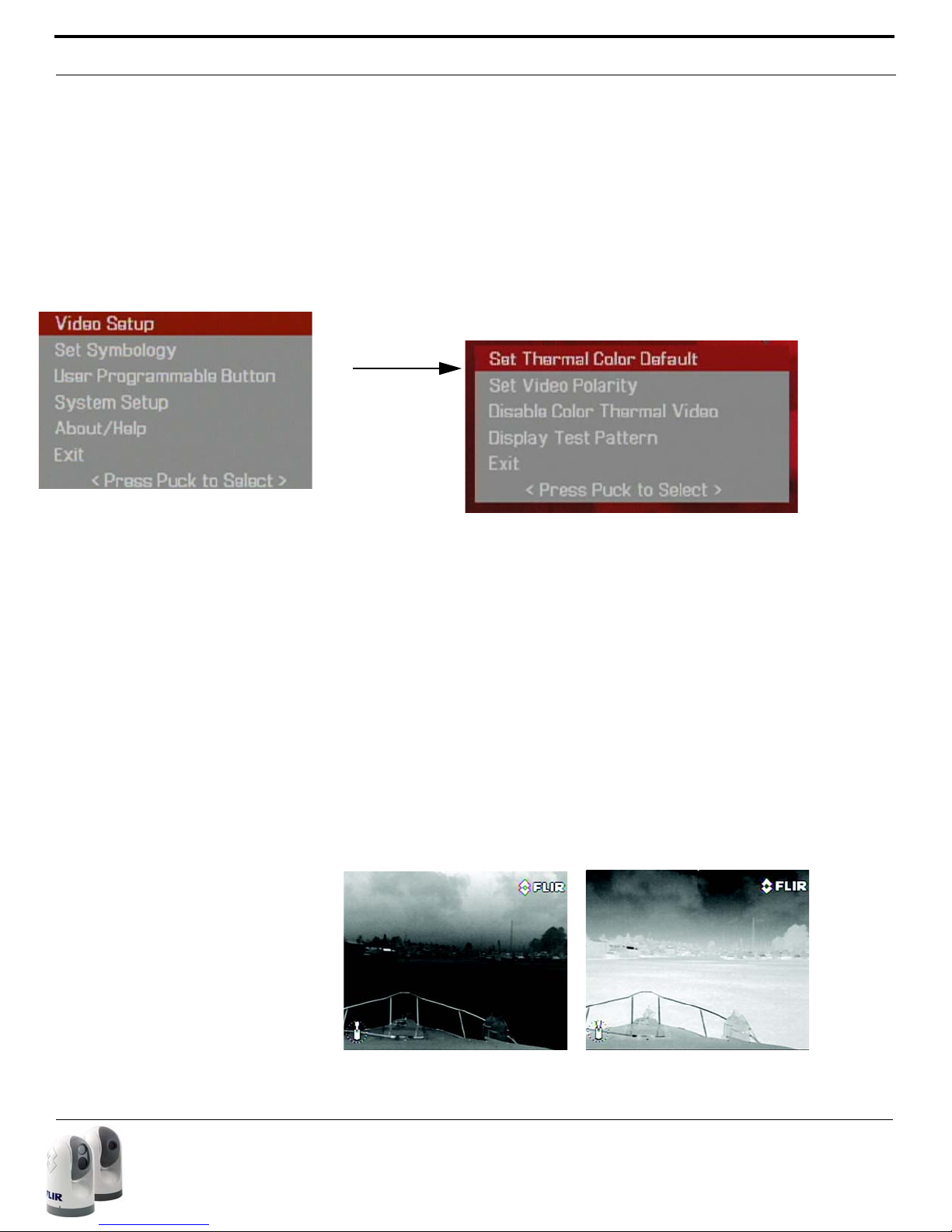
Video Setup Menu
From the main menu (shown at the left), the Video Setup entry will lead to
the following menu.
This menu is used to set the video configuration options.
Set Thermal Color Default
The Set Thermal Color Default saves the current Color setting as the default
value. This setting will be used when the system is booted up. When this
menu entry is selected, the menu entry changes to “Thermal Color Default
Saved” until Exit is selected.
Set Video Polarity
Selecting this item will toggle the infrared imagery from white-hot (or redhot, if the COLOR setting is active) to black-hot. The difference between
white-hot and black-hot is shown below; white-hot is on the left and black-hot
on the right. The use of white-hot or black-hot display mode is strictly a personal preference; experiment with the different settings in different conditions and see which is preferred.
432-0003-00-10 rev 140 M-Series Operator’s Manual 31
Page 30
Configuration Menus
Note: By default, the USER button is configured with the Invert Video Polar-
ity setting, so it can be used to toggle the video polarity. However, the function of the USER button can be changed from the factory default setting to
do other functions. Refer to the User Programmable Button section for
more information about how to program the USER button.
Enable (Disable) Color Thermal Video
Many people prefer to look at the thermal images in color instead of grayscale. When this menu item is enabled, the camera uses all five color palettes available. The JCU COLOR button will cycle through all five settings:
greyscale, red, glowbow, rainbow and fusion, instead of just two settings.
When it is disabled, the three color palettes (rainbow, sepia and fusion) are
not available. This option is enabled by default.
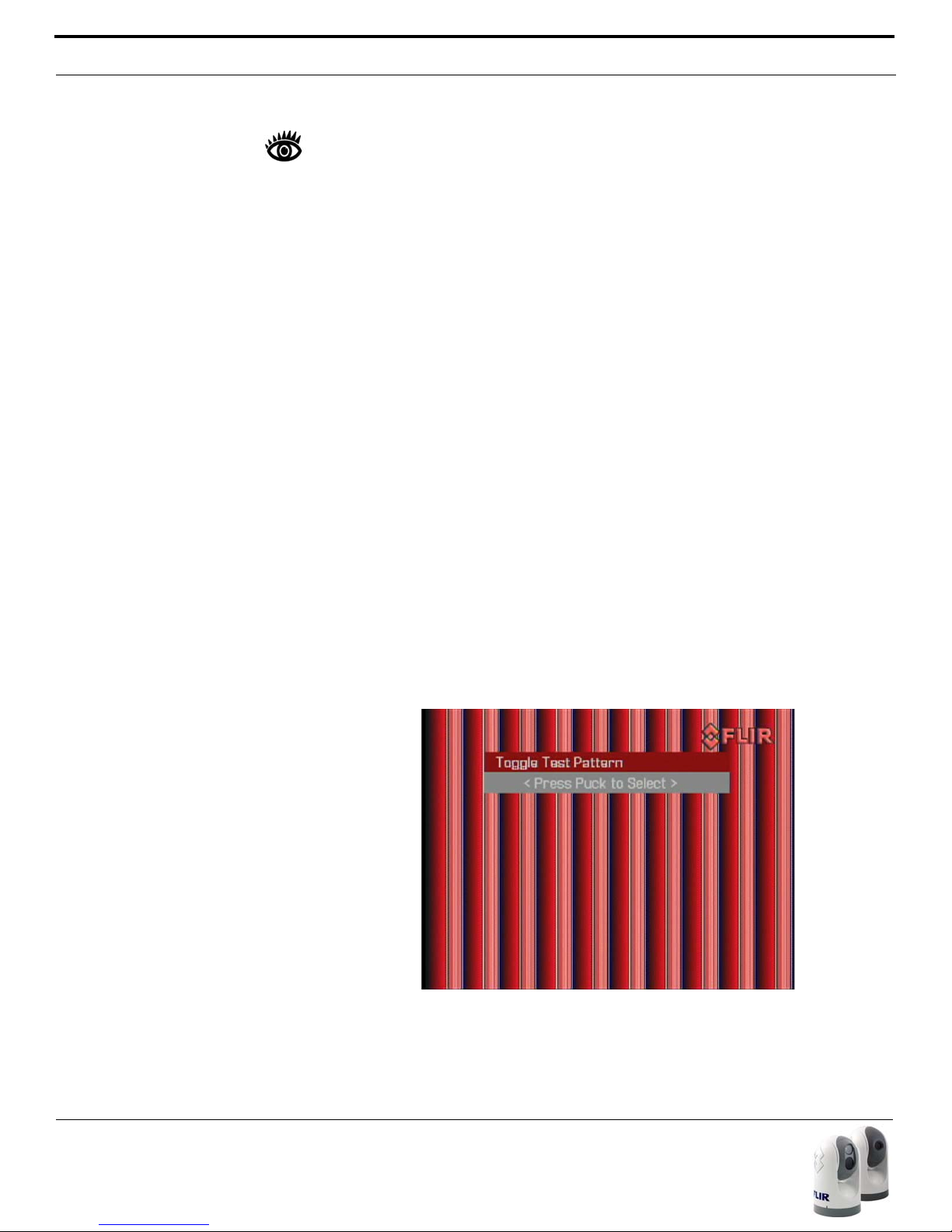
Display Test Pattern
Quite often the video from the M-Series camera can be optimized by adjusting the monitor that is being used to show the video. The Display Test Pattern function is useful for setting up the monitor to give the best detail and
contrast.
When the Display Test Pattern entry is selected, the Toggle Test Pattern
menu is displayed, and the user is prompted to press the puck to select a
test pattern. Pressing the puck repeatedly will cycle through the four test
patterns.
When a test pattern is displayed, the monitor brightness and contrast, can
be adjusted to give the best image.
32 432-0003-00-10 rev 140 M-Series Operator’s Manual
Page 31

Configuration Menus
Main On-Screen Menu
Set Symbology
From the main menu (shown at the left), the Set Symbology entry will lead to
the following menu:
Icon Display
The PC Icon and the JCU Icon can be enabled or disabled using the first two
menu entries.
Note: The PC Icon will only appear if the system has discovered a PC on the
network.
The other icons on the screen are controlled by selecting one of the three
settings shown on the menu: Display All Icons, Display Minimal Icons, and
Hide All Icons. The default setting is Display Minimal Icons.
Display All Icons
Selecting this menu item will turn on all the on-screen icons at all times.
Some icons are only displayed momentarily (for example, the Home Icon).
Display Minimal Icons
When the Minimal Icon mode is selected, the Position Indicator is displayed
continuously on screen. The Home and Scene icons will display on screen
for 3 seconds only before disappearing. The Zoom (2X and 4X
1
), Rearview,
and Image Freeze icons are displayed whenever those functions are active.
Hide All Icons
Selecting this menu item will turn off most of the on-screen icons except
when their corresponding controls are actively in use. The Position Indicator
and the FLIR logo are always displayed.
1 Note, 4X Zoom not available on all models.
432-0003-00-10 rev 140 M-Series Operator’s Manual 33
Page 32

Configuration Menus
Main On-Screen Menu
Note: It is also possible to enter
this menu by pressing and holding
the USER button for 3 seconds.
User Programmable Button
From the main menu (shown at the left), the User Programmable Button
entry will lead to the following menu:
The USER button is a programmable one-touch button. It is intended to
allow the user to quickly access the most common or favorite settings or
functions. This menu allows the user to select how the USER button will
function. The user can select one of the five choices; the Invert Video Polarity is the default selection. The active choice is shown in black type.
Man-Over-Board Settings - pressing the USER button causes the thermal
camera to use the Man Overboard AGC setting.
Switch IR/VIS Video (this option is available on dual payload models only) pressing the USER button causes the video signal on the cable labeled
“VIS/IR” to toggle between the thermal camera and the visible-light camera.
Troubleshooting Tip: If this mode is selected, but pressing the USER button
does not cause the display to switch from the thermal camera to the visiblelight camera, be sure the proper input channel is selected on the display,
and be sure the cable labeled “VIS/IR” is connected to the display.
Hide/Show All Icons - pressing the USER button toggles between the Hide
All Icons menu setting and the Show All Icons setting (refer to the Set Symbology section for more information).
Invert Video Polarity - pressing the USER button will toggle the infrared
imagery between white-hot (or red-hot, if the COLOR setting is active) and
black-hot.
Rearview Mode (Revert) - pressing the USER button enables or disables
the Rearview Mode, which causes the video image to be flipped horizontally
(revert). If Rearview Mode is enabled, the Rearview mirror icon will be displayed on the screen.
34 432-0003-00-10 rev 140 M-Series Operator’s Manual
Surveillance Mode - pressing the USER button enables or disables the
Surveillance Mode. Refer to the Surveillance Mode section below for more
information about this mode of operation.
Page 33

Configuration Menus
Main On-Screen Menu
System Setup
From the main menu (shown at the left), the System Setup entry will lead to
the following menu:
Enable (Disable) Ball-Down Installation
This menu option should be enabled when the camera is mounted upside
down in the “ball-down” configuration. If it is not enabled, the video signal will
be upside down on the monitor. When the Ball-Down mode is first enabled,
the camera to rotate 180 degrees and the camera ball will flip over. This
option is disabled by default.
Enable (Disable) Aircraft Joystick Mode
The joystick can be used in either “aircraft” or “gaming” mode. The choice of
which mode to use is a matter of personal preference. One mode may feel
more natural than the other. When Aircraft Joystick Mode is enabled, moving the joystick forward causes the camera to tilt down. When disabled,
moving the joystick forward causes the camera to tilt up. The default mode
is disabled.
Enable (Disable) Twist-to-Pan Mode
This menu entry enables or disables the Twist-To-Pan mode. The default JCU
setting for the Puck is "twist to pan"; alternatively, you can change the Puck
setting so that the camera is panned by moving the Puck to the left or right,
rather than rotating (twisting) it. The Zoom Function is also assigned to
"twisting left/right" when "twist to pan is disabled.
432-0003-00-10 rev 140 M-Series Operator’s Manual 35
Page 34

Configuration Menus
Enable (Disable) High Power Standby
This menu entry controls the amount of power that is supplied to the pan/
tilt motors while the camera is in the Standby mode. Choosing the amount
of power to use involves a trade-off between power consumption and the
ability of the gimbal assembly to hold the camera in place in rough seas. If
the gimbal moves due to shock or vibration, the camera may not be in line
with the Position Indicator or may lose precision regarding the Home position.
The High Power Standby mode may be useful for power boats that operate
at higher speeds and experience high impact environments, and can accept
higher power consumption.
Note: The High Power Standby mode is enabled by default; for vessels such
as sailboats with a limited power budget, it may be wise to disable the High
Power mode. Refer to the Power Consumption table below.
Note: If the gimbal moves due to shock or vibration rather than a command
from the JCU, the camera can be reset by repeated pressing of the HOME
button 4 times.
When the Enable or Disable selection is made, the camera prompts the
user to confirm or cancel the selection.
Enable (Disable) High Motor Torque
This menu entry controls the amount of power that is supplied to the pan/
tilt motors while the camera is in the Powered On mode. As with the High
Power Standby mode option, choosing the amount of motor torque to use
involves a trade-off between power consumption and the ability of the gimbal assembly to hold the camera in place in rough seas. Also a trade-off
with camera readiness delay is possible in cold environments while the system reaches operational temperature.
The High Motor Torque mode may be useful for power boats that operate
at higher speeds and experience high impact environments, and can accept
higher power consumption.
Note: The High Motor Torque mode is enabled by default; for vessels such
as sailboats with a limited power budget, it may be wise to disable the High
Power mode. Refer to the Power Consumption table below.
Note: If the gimbal moves due to shock or vibration rather than a command
from the JCU, the camera can be reset by repeated pressing of the HOME
button 4 times.
36 432-0003-00-10 rev 140 M-Series Operator’s Manual
Page 35

Configuration Menus
When the Enable or Disable selection is made, the camera prompts the
user to confirm or cancel the selection.
TABLE 1. Power Consumption
Camera
State Camera setting
Dual
Payload
Single
Payload
Standby High Power Mode ON 22W 17.4W
High Torque Mode ON
Standby High Power Mode OFF 8W 7.4W
High Torque Mode ON
Standby High Power Mode ON 13W 13W
High Torque Mode OFF
Standby High Power Mode OFF 8W 7.4W
High Torque Mode OFF
Awake High Power Mode ON or OFF 30W 19.4W
High Torque Mode ON
Awake High Power Mode ON or OFF 20W 16.5W
High Torque Mode OFF
The above power numbers assume a single JCU is plugged into the camera
and window heaters are not active. For a dual-payload camera, an additional
16W is consumed when window heaters are active for a maximum power
consumption of under 46 W. For single payload, when heaters are active
there is an additional 6.5W, for a maximum power consumption of under
26W.
Enable (Disable) Rearview Mode
This menu entry enables or disables the Rearview Mode, which causes the
video image to be flipped horizontally (revert). The image on the display provides the same perspective as a rear view mirror in a vehicle - objects off
the stern on the starboard side of the vessel are displayed on the right hand
side of the video. If Rearview Mode is enabled, the Rearview mirror icon will
be displayed on the screen. It is possible to configure the USER button to
enable or disable the Rearview Mode.
Set Stow Position
When Set Stow Position is selected, the camera stores the current position
(camera azimuth and elevation) as the Stow position. The camera moves to
432-0003-00-10 rev 140 M-Series Operator’s Manual 37
Page 36

Configuration Menus
the Stow position when it is turned off (put into Standby mode). Refer to the
System Startup section for additional information about the Standby mode.
Note: The Stow position is not the same as the Home position. The Home
position is the position the camera will most likely be in when the camera is
in use. The Stow position is the preferred position when the camera is not
in use, for protecting the camera optics. Both positions are programmable
by the user; refer to the Operation/Configuration Using JCU Buttons section for additional information regarding the Home position.
Name Camera
The Name Camera can be used to give the camera a new name. When the
Name Camera function is selected, the current name is displayed on the
screen, and the first character of the name is blinking. The puck can be
moved fore and aft (or twisted) to change the character. The next character can be selected by moving the puck to the right.
The possible characters that can be used include the letters of the alphabet
(upper or lower case), the numbers 0-9, and the hyphen symbol (-). When
the name has been entered completely, push the puck to exit.
Then confirm the new camera name or cancel and continue making
changes. When you are finished, select Exit.
Surveillance Mode
The Surveillance Mode entry will lead to the following menu:
The User Programmable Button can be programmed to enable or disable
Surveillance Mode (refer to the section above called User Programmable
Button). When the USER button is configured with the Surveillance Mode
setting, the Surveillance Mode will be enabled when the USER button is
pressed. When the camera is in Surveillance Mode, it will cause the cam-
38 432-0003-00-10 rev 140 M-Series Operator’s Manual
Page 37

Configuration Menus
Note: The center of the scan pattern is determined by the direction
the camera is pointing when the
USER button is pressed. The scan
pattern is not centered about the
Home position, unless the camera
is in the Home position when the
USER button is pressed.
Narrow
Medium
Wide
era to continuously pan left and right, until it is taken out of Surveillance
Mode or until the JCU is used to move the camera. The camera will not
resume Surveillance Mode automatically; it is necessary to enable Surveillance Mode again by pressing the USER button.
Scan Width
In Surveillance Mode, the Scan Width determines the range of horizontal
azimuth (pan) covered by each scan. The choices are Narrow, Medium, and
Wide. If the Scan Width is set to Narrow, the camera will scan from approx-
imately 20
by which direction the camera is pointing when the USER button is pressed.
The Medium scan width covers an area 40
o
total), and the Wide scan width covers 80o to the left and right of cen-
(80
ter (160
o
left of center to 20o right of center, with the center determined
o
to the left and right of center
o
total).
Scan Speed
In Surveillance Mode, the Scan Width determines how quickly the camera
scans back and forth. The choices are Fast, Medium, and Slow.
Note: the scan speed is affected by the zoom state (if the camera is
zoomed in, it will scan at a slower rate). The default scan speed is Slow; try
all three settings to determine which is best for your installation.
432-0003-00-10 rev 140 M-Series Operator’s Manual 39
Page 38

Configuration Menus
Main On-Screen Menu
About/Help
From the main menu (shown at the left), the About/Help entry will lead to
the following menu:
Video Icon Help Screens
The Video Icon Help Screens provide an on-screen explanation of the meaning of each of the screen icons. The icons are shown on two screens; press
the JCU puck to cycle through the help screens.
40 432-0003-00-10 rev 140 M-Series Operator’s Manual
Page 39

Configuration Menus
About/Help Menu
About/Help Menu
Product Information
Selecting the Product Information menu entry will display on the screen the
product information, such as the camera model, serial number, and software release information. When contacting FLIR, please have this information available.
Contact FLIR
Selecting the Contact FLIR menu entry will cause the FLIR contact information to be displayed on the screen. Additional contact information is included
at the back of this manual. When contacting FLIR, please have the product
information available (see above).
432-0003-00-10 rev 140 M-Series Operator’s Manual 41
Page 40

System Reset Functions
About/Help Menu
Restore Factory Defaults
Select this item to restore the M-Series to its factory default settings. The
camera will prompt the user to confirm if the camera is to be restored to
the factory default settings.
Refer to Factory Default Settings table for a list of the factory default settings.
System Reset Functions
JCU Reset
Occasionally it may be necessary to reset the JCU. Simultaneously pressing
the MENU and USER buttons for >3 seconds causes the JCU to reset.
Unplugging and plugging the Ethernet will also cause the JCU to lose power
temporarily and reset.
Camera Reset
Severe vibrations or shock may cause the camera gimbal assembly to
rotate or tilt and cause the Position Indicator to be inaccurate. To reset the
camera and cause the gimbal assembly to go through its initial pan/tilt
cycle, repeatedly press the HOME button 4 times.
Note: the High Power Standby and High Motor Torque settings can be
enabled to provide the camera with a better ability to withstand shock and
vibration at high rates of speed or in high seas.
42 432-0003-00-10 rev 140 M-Series Operator’s Manual
Page 41

Operation Tips
Operation Tips
As you experiment with the M-Series, you will see the world in a different
light. Consider every object you view in terms of how it will look “thermally”
as opposed to how it looks to your eye. Right after sunset, objects warmed
by the sun will appear warmest. Early in the morning, many of these objects
will appear cooler than their surroundings, so be sure to look for subtle
ball-down differences in the scene, as opposed to just hot targets.
Originally developed for the military, thermal imaging cameras are now
deployed in numerous commercial applications where it is impractical or too
expensive to use active illumination (lights). They are perfect for a wide variety of applications in addition to maritime, including transportation, security,
fire fighting, and medical applications. The cameras often provide improved
daytime viewing in environments where traditional video camera performance suffers, such as in shadows or backlit scenes.
The M-Series camera is a state-of-the-art thermal imaging system that will
provide you with excellent night visibility and situational awareness, without
any form of natural or artificial illumination. The system is easy to use, but
you should take a moment to understand how to interpret what you are seeing on your display and how to use the controls.
While the imagery you will see on the monitor may at first look similar to
ordinary black and white daylight video, as you get familiar with the camera
you will appreciate the characteristics that make thermal imaging distinct. A
few tips on how to interpret some of the imagery will help you to make the
most of your system.
The thermal imager inside the camera does not sense light like conventional
cameras; it senses heat or temperature differences. As you experiment
with the system during daylight and nighttime operation, you will notice differences in the picture quality; this is normal. The camera senses small "differences" in apparent radiation from the objects in view, and, in white hot
mode, displays them as either white (or lighter shades of grey) for warmer
objects, and black (or darker shades of grey) for colder objects.
Your thermal imaging camera relies on the fact that all objects, even very
cold objects like ice, emit thermal energy in the portion of the infrared spectrum that this camera can "see", the long wave infrared (LWIR). Therefore,
unlike an illuminated infrared camera, a thermal imaging camera does not
need an additional active illumination source and images based on directly
radiated rather than reflected energy.
This is why you will see hot objects such as parts on an outboard motor that
appear white (or black, or red depending on the video image mode
selected), while the puddles of water and other cold objects appear dark (or
cool). Scenes with familiar objects will be easy to interpret with some experi-
432-0003-00-10 rev 140 M-Series Operator’s Manual 43
Page 42

Troubleshooting Tips
ence. The camera automatically optimizes the image to provide you with the
best contrast in most conditions.
FLIR Systems, Inc. offers a comprehensive selection of training courses to
help you to get the best performance and value from your thermal imaging
camera. You can find out more at the FLIR training web page:
http://www.flir.com/training.
If you have any questions about the operation of the M-Series, or you would
like to provide feedback on the product, please feel free to call us at
1.888.747.FLIR in the United States.
Troubleshooting Tips
Video not displayed on monitor
The camera will not display video if it is in Standby mode. Power Cycle the
camera and allow the system to complete boot cycle prior to JCU connection. Ensure the JCU is assigned to the camera, the camera name appears
in the JCU display, and the camera responds to JCU input (for example,
pan/tilt movements).
If the camera will not produce an image, check the video connection at the
camera and at your display. If the connectors appear to be properly connected but the camera still does not produce an image, ensure that power
has been properly applied to the camera and circuit breaker is set properly.
If a fuse was used, be sure the fuse is not blown.
If the camera still does not produce an image, contact the FLIR dealer or
reseller who provided the camera, or contact FLIR directly (contact information is provided on the rear cover of this manual).
Video not switching between thermal and visible (dual payload models
only)
On a dual payload model, the display can be switched between the thermal
camera and the visible camera either by pressing and holding the SCENE
button, or, if the User Programmable Button mode is set to Switch IR/VIS
Video, pressing the USER button. If neither of these operations will cause
the display to switch from the thermal camera to the visible-light camera,
be sure the proper input channel is selected on the display, and be sure the
cable labeled “VIS/IR” is connected to the display.
44 432-0003-00-10 rev 140 M-Series Operator’s Manual
Page 43

Troubleshooting Tips
Noisy image
A noisy image is usually attributed to a cable problem (too long or inferior
quality) or the cable is picking up electromagnetic interference (EMI) from
another device. Although coax cable has built-in losses, the longer the cable
is (or the smaller the wire gauge/thickness), the more severe the losses
become; and the higher the signal frequency, the more pronounced the
losses. Unfortunately this is one of the most common and unnecessary
problems that plagues video systems in general.
Cable characteristics are determined by a number of factors (core material,
dielectric material and shield construction, among others) and must be
carefully matched to the specific application. Moreover, the transmission
characteristics of the cable will be influenced by the physical environment
through which the cable is run and the method of installation. Use only high
quality cable and ensure the cable is suitable to the marine environment.
Check cable connector terminations. Inferior quality connections may use
multiple adapters which can cause unacceptable noise. Use the FLIR Video
Distribution Amp when splitting the signal to multiple monitors.
Image too dark or too light
By default the M-Series thermal camera uses an Automatic Gain Control
(AGC) setting that has proven to be superior for most applications, but a
particular environment may benefit from a different AGC setting. For example, a very cold background (such as the sky) could cause the camera to use
a wider temperature range than appropriate. The user should keep the
ocean, and not the sky or the boat, as the predominant object in the image.
Refer to the Video Setup Menu section for information about how to make
adjustments to the image with the SCENE button.
Performance varies with time of day
You may observe differences in the way the camera performs at different
times of the day, due to the diurnal cycle of the sun. Recall that the camera
produces an image based on temperature differences.
At certain times of the day, such as just before dawn, the objects in the
image scene may all be roughly the same temperature, compared to other
times of the day. Compare this to imagery right after sunset, when objects
in the image may be radiating heat energy that has been absorbed during
the day due to solar loading. Greater temperature differences in the scene
generally will allow the camera to produce high-contrast imagery.
Performance may also be affected when objects in the scene are wet rather
than dry, such as on a foggy day or in the early morning when everything
may be coated with dew. Under these conditions, it may be difficult for the
432-0003-00-10 rev 140 M-Series Operator’s Manual 45
Page 44

Troubleshooting Tips
camera to show the temperature the object itself, rather than of the water
coating.
Eastern or Western Exposure
While under way, the camera may inevitably end up pointing directly east or
west, and this may cause the sun to be in the field of view during certain
portions of the day. We do not recommend intentionally viewing the sun,
but looking at the sun will not permanently damage the sensor. In fact the
thermal imaging camera often provides a considerable advantage over a
conventional camera in this type of back-lit situation. However, the sun may
introduce image artifacts that will eventually correct out. and it may take
some time for the camera to recover. The amount of time needed for
recovery will depend on how long the camera was exposed to the sun. The
longer the exposure, the longer the recovery time needed.
Image freezes momentarily
The camera has a feature that allows the user to momentarily freeze the
image. Double click (press down quickly two times) on the JCU puck to
freeze the image. The snowflake Image Freeze icon will appear on the
screen. Any any other action with the JCU (moving the puck or pushing a
button) will unfreeze the image.
By design, the camera image will freeze momentarily on a periodic basis
during the Flat Field Correction (FFC) cycle. Periodically the image will
momentarily freeze for a fraction of a second while the camera performs a
flat field correction. A shutter activates inside the camera and provides a
target of uniform temperature, allowing the camera to correct for ambient
temperature changes and provide the best possible image. Just prior to
the FFC, a small green square will appear in the upper left corner of the
screen.
Note: Pressing and holding the COLOR button will cause the thermal
camera to do an FFC operation.
Multiple Cameras and/or JCUs on a single network
It is possible to have multiple cameras and multiple JCUs on the same network. More than one JCU can be used to control a given camera. The camera will respond to commands from both JCUs in the order the commands
are received across the network. Unpredictable behavior may result from
users sending conflicting commands from separate JCUs (for example, one
user pans left and the other user pans right). In general, the camera will
respond to the last command received and there is no way to set priority,
given that IP networks use a “best effort” delivery protocol.
46 432-0003-00-10 rev 140 M-Series Operator’s Manual
Page 45

Troubleshooting Tips
On Screen Messages
In some circumstances, a status or alert message may appear on the video
screen. This section describes the messages and the appropriate actions
that may be necessary.
"Loading, please wait…"
Indicates the camera has power and is booting up. No action is needed; the
message will be removed when camera is ready for operation.Refer to
Chapter 2 System Startup for more information.
"Reconnect network, now..."
Indicates the camera has detected a loopback termination on the Ethernet
RJ45 connector and has reverted to the Factory Default network settings
Remove the Ethernet RJ45 loopback termination adapter. The camera will
then continue the start-up process under the Factory Default network configuration (with DHCP dynamic IP addressing).
2
.
"Warming, please wait…
Indicates the camera has detected a low temperature condition and does
not allow pan/tilt motion until it is sufficiently warm. Wait for the camera to
self-heat to an operational temperature (the amount of time will vary
depending on the outside temperature). The message will be removed when
camera is ready to operate.
"High Temperature - Motor Halted"
Indicates the camera has detected an over-temperature condition and has
disabled the internal pan/tilt motor power. Confirm the temperature of the
camera is within the allowed operational temperature range. Allow the camera to cool down to a temperature within the operating range.
"High Temp. - Shutdown System #"
Indicates the camera has detected an over-temperature condition and must
be shutdown. The '#' character displays a 5 second countdown. The user
should onfirm the temperature of the camera is within the allowed operational temperature range. Turn off the power to the camera and allow it to
cool down to a temperature within the operating range. If the problem continues, contact FLIR.
2 Refer to the following section for more information about the RJ45 loopback con-
nector and how to restore the network settings to factory defaults.
432-0003-00-10 rev 140 M-Series Operator’s Manual 47
Page 46

Troubleshooting Tips
Restoring the Factory Network Settings
In some cases, it may be necessary to restore the network settings of the
camera to the original factory settings. At each power-up, the system
transmits a packet and then checks to determine if that same packet has
been recieved. Detection of the received packet indicates the camera has a
custom loopback connector installed on its Ethernet interface. The detection of the loopback packet cues the camera to restore Factory Defaults
and to revert to the same configuration and behavior as when the camera
left the factory.
The custom loopback connector is described below.
Pin # Signal Tied to pin #
1Transmit +3
2Transmit - 6
3 Receive + 1
4UnusedN/A
5UnusedN/A
6 Receive - 2
7UnusedN/A
8UnusedN/A
The RJ45 loopback termination ties pin 1 to pin 3, and pin 2 to pin 6. The
other pins are not connected.
48 432-0003-00-10 rev 140 M-Series Operator’s Manual
Page 47
CHAPTER 4 M-Series IP Interface
M-Series IP Interface and PC Operations
The M-Series cameras and JCUs are network devices that communicate
over an Ethernet network using the Internet Protocol (IP). In addition to
using a JCU to control and configure a camera, a user or installer can also
do similar operations (and even more advanced configurations) using a web
browser
face also allows marine electronics integrators with software development
capabilities to design customized applications that integrate the camera and
JCU capabilities with other types of marine electronics.
1
when a PC or a laptop is connected to the network. This IP inter-
This chapter describes how to use a web browser to communicate with and
configure the M-Series cameras and JCUs. Integrators are encouraged to
contact FLIR directly to obtain more detailed information about the Nexus
Software Developer’s Kit (SDK) and the communication protocols supported
on the M-Series cameras and JCUs: +1.888.747.3547.
In most M-Series camera installations, a PC may not be needed or used.
One or more JCUs will allow complete control and configuration of all the
cameras on the network.The M-Series web interface may be useful for more
complex installations that have other devices on the network or a need for
customization.
1 Supported web browsers: Microsoft Internet Explorer version 7 or 8 on PC plat-
forms running Microsoft Windows. Internet Explorer 8 may have to be configured
to run in compatibility mode.
432-0003-00-10 rev 140 M-Series Operator’s Manual 49
Page 48

M-Series IP Interface and PC Operations
M-Series Web Control
If you have a PC on the same network as the camera and JCU, you can use
the PC to control and configure the system, the same as you would with the
JCU. The cameras, JCUs and PCs are able to communicate with each
other via the HTTP protocol.
Generally the same controls and functions that are available from the JCU
are also available through the web interface. As shown in the screen shot
below, the JCU functions and menu options described in the previous chapters are represented as web links in blue boxes that are arranged in several groups. A link becomes highlighted when you mouse over it (the text
changes from white to grey).
50 432-0003-00-10 rev 140 M-Series Operator’s Manual
Page 49

M-Series IP Interface and PC Operations
Web Control Functions
For the most part, each link on the Web Control page corresponds to an
equivalent operation on the JCU or with the System Menu, as the table
below indicates. The table assumes the factory default settings are being
used. For a more detailed description of each function, refer to the appropriate section in the previous chapters of this manual.
TABLE 1. Web links and the equivalent JCU/Menu operation
Web Control
Link
Equivalent
Operation Comment
Pan and Tilt
Home JCU: Press
HOME button
Click and hold to set the home position.
Stop Stops all movement of the camera,
including Surveillance Mode. No
equivalent JCU function
Camera Controls
Active JCU: Press
POWER/Dim
button
Standby JCU: Press and
hold POWER/
Dim button
Speed (pulldown)
Controls the speed of pan and tilt
operations; Possible selections:
40, 60, 80
Product Information
MENU: About/
Help > Product
See below for an example
Information
Network Setup Refer to the Network Setup section
that follows
Joystick Control
Left JCU: Push Puck
left
With Twist-to-Pan mode enabled
(default), pressing the puck left/
right does nothing.
Right JCU: Push Puck
right
With Twist-to-Pan mode disabled,
clicking on Left or Right causes the
camera to pan left or right.
432-0003-00-10 rev 140 M-Series Operator’s Manual 51
Page 50

M-Series IP Interface and PC Operations
TABLE 1. Web links and the equivalent JCU/Menu operation
Web Control
Link
Equivalent
Operation Comment
Twist - JCU: Twist Puck
counterclockwise
Twist + JCU: Twist Puck
clockwise
Down JCU: Pull Puck
backward
(toward user)
Up JCU: Push Puck
forward (away
from user)
Press Puck JCU: Press
Puck into JCU
Pull Puck JCU: Pull Puck
out from JCU
Menu JCU: Press
MENU button
User JCU: Press
USER button
Color JCU: Press
COLOR button
Scene JCU: Press
SCENE button
Freeze JCU: Double
click Puck
(press down
twice quickly).
With Twist-to-Pan mode enabled
(default), twisting the puck will
cause the camera to pan left or
right.
When Twist-to-Pan is disabled,
twisting the puck will cause the IR
camera to zoom in/out.
Controls camera tilt (direction
depends on Aircraft Joystick
mode); used to na vigate menu in all
modes.
Controls camera tilt (direction
depends on Aircraft Joystick
mode); used to na vigate menu in all
modes.
With Twist-to-Pan mode enabled
(default), pressing the puck will
cause the IR camera to zoom in.
Also functions as “enter” when
using Menu functions.
With Twist-to-Pan mode enabled
(default), pulling the puck will cause
the IR camera to zoom out.
Opens or closes the on-screen
menu.
Operation depends on the User
Programmable Button setting;
Invert Video Polarity is the default
Cycles through the various Color
settings.
Cycles through the various Scene
settings. On a dual payload camera, click and hold to toggle VIS/IR
video between IR and Visible camera.
To unfreeze, click any link on the
page (except Product Information
or Network Setup). On the JCU,
press any button or move the joystick to unfreeze.
52 432-0003-00-10 rev 140 M-Series Operator’s Manual
Page 51

M-Series IP Interface and PC Operations
TABLE 1. Web links and the equivalent JCU/Menu operation
Web Control
Link
Equivalent
Operation Comment
Zoom + JCU: Push Puck
down for 1 second to turn on
2X electronic
zoom
Zoom - JCU: Pull up on
the Puck
Menu Options
Display Minimal Icons
MENU: Set
Symbology >
Display Minimal
Icons
Display All
Icons
MENU: Set
Symbology >
Display All Icons
Hide All Icons MENU: Set
Symbology >
Hide All Icons
Enable High
Power
MENU: System
Setup > Enable
High Power
Standby
Enable High
Torq u e
MENU: System
Setup > Enable
High Motor
Torq u e
Set Stow Position
MENU: System
Setup > Set
Stow Position
Switch IR/VIS JCU: Press and
hold the SCENE
button
Set Default
Color
MENU: Video
Setup > Set
Thermal Color
Default
This function is only valid for dual
payload cameras. If the User Programmable Button is set to Switch
IR/VIS Video, then the USER button can also be used to switch
channels.
432-0003-00-10 rev 140 M-Series Operator’s Manual 53
Page 52

M-Series IP Interface and PC Operations
TABLE 1. Web links and the equivalent JCU/Menu operation
Web Control
Link
Switch Video
Polarity
Equivalent
Operation Comment
MENU: Video
Setup > Set
Video Polarity
Start Surveillance Scan
JCU: Press
USER button
The User Programmable Button
must be set to Surveillance Mode.
To stop the scan, click Stop, Home,
or any of the Joystick Control links
that control camera movement.
Switch Rearview Mode
MENU: System
Setup > Enable
(Disable) Rearview Mode
Tex t Fields
Camera Name This field displays the camera
name. It is not possible to change
the camera name with this field.
Use MENU: System Setup > Name
Camera function to set/change the
name of the camera.
TX Read-only field displaying com-
mands sent to camera using FLIR
Network Application Programming
Interface (API) protocol.
RX Read-only field displaying camera
acknowledgement of the received
command
54 432-0003-00-10 rev 140 M-Series Operator’s Manual
Page 53

M-Series IP Interface and PC Operations
UPnP Configuration
In order to use the Web Interface, the PC may need to be setup to use Universal Plug and Play (UPnP), which is not normally active on most PCs.
Universal Plug and Play
UPnP is a set of networking protocols that allow devices on a network to
connect automatically, without the need for configuration by a network
expert. The intent of UPnP is to simplify the implementation of networks and
the installation of computer components. A UPnP compatible device from
any vendor can dynamically join a network, obtain an IP address, announce
its name, convey its capabilities upon request, and learn about the presence
and capabilities of other devices.
UPnP devices are "plug-and-play" in that when connected to a network they
automatically announce information about themselves and supported device
and services types, enabling clients that recognize those types to immediately begin using the device.
M-Series cameras and JCUs are UPnP devices so they broadcast their
presence on the network. A PC configured to accept UPnP broadcasts will
show all UPnP devices discovered under My Network Places, but by default
PCs are not set up to accept UPnP broadcasts.
Users need to activate UPnP on their computers so that M-Series cameras
or JCUs can be found. The JCU and camera use this same process to connect to one another.
Enabling the UPnP User Interface
In some cases, Windows will discover UPnP devices and provide its own
user interface to control them. Windows Vista and Windows 7 automatically detect network devices in the "Network" page. If UPnP devices are hidden a prompt at the top of the screen will ask if you would like to display
hidden devices.
With Windows XP, you can install the optional User Interface (UI) component
using the steps below. This UI component displays a balloon tip for newly discovered devices and places an icon for each device in the My Network
Places folder. To enable the UPnP UI, follow these steps:
1. Click Start, click Control Panel, and then click
2. Add or Remove Programs. In the Add or Remove Programs dialog box,
click Add/Remove Windows Components.
432-0003-00-10 rev 140 M-Series Operator’s Manual 55
Page 54

M-Series IP Interface and PC Operations
3. In the Windows Components Wizard, click Networking Services, click
Details, and then select the Universal Plug and Play check box.
56 432-0003-00-10 rev 140 M-Series Operator’s Manual
Page 55

M-Series IP Interface and PC Operations
4. Click OK, and then click Next in the Windows Components Wizard. You
may need to provide your Windows XP installation CD
You can now see if any UPnP-enabled devices exist on your network by opening My Network Places. If there are UPnP devices on your local network,
they will appear here with a generic icon based on the device type. In the
future when a UPnP device is installed on the network, a notifying icon will
appear briefly in the System Tray. When you see this icon, go to My Network
Places to view the new device. Double-click on the icon to bring up the web
page.
PC Icon
On the M-Series video output, the PC Icon indicates there is a PC on the network that has a connection with the camera.
JCU Icon
A single JCU Icon indicates only one JCU is currently connected to the camera unit. If more than one JCU is discovered, the multiple JCU icon will
appear on screen.
432-0003-00-10 rev 140 M-Series Operator’s Manual 57
Page 56

Network Settings
Network Settings
IP Addresses
By default, the camera and JCU device are configured to automatically
determine IP addresses dynamically through UPnP. It is also possible to configure static IP addresses to coincide with addresses on an existing network.
Note: On the JCU, the IP address is displayed by pressing the COLOR button and Puck at the same time. The IP is displayed for 3 seconds and then
returns to the Camera name it had prior or the state it was in before the IP
request was made.
Note: it is not possible to display the camera’s IP address on the JCU display.
When the Network Settings link is selected, the camera IP address, Mask,
and Gateway are displayed, as show in the screen shot below. The Dynamic
option is selected by default.
58 432-0003-00-10 rev 140 M-Series Operator’s Manual
Page 57

Network Settings
Static IP Address
To enter a static IP address, select the Static option rather than Dynamic.
The screen will refresh, and the IP, Mask, and Gateway fields will change
from grey to white, indicating they can accept user entries. Once you have
entered the appropriate information, click on the Save link.
Note: When the IP address is
changed, the browser window
opened under the old IP address
will no longer be valid.
Type the new static IP address
into the browser, or return to
“Network” (Win 7/Vista) or "My
Network Places" (Win XP) to
find the camera (UPnP broadcast is never disabled for MSeries cameras, even when
using a static IP address).
As soon as you select Save, the system will give a warning as it restarts the
Network stack:
When the camera is in Static mode, clicking on the “Factory IP Defaults” link
will result in the following warning:
432-0003-00-10 rev 140 M-Series Operator’s Manual 59
Page 58
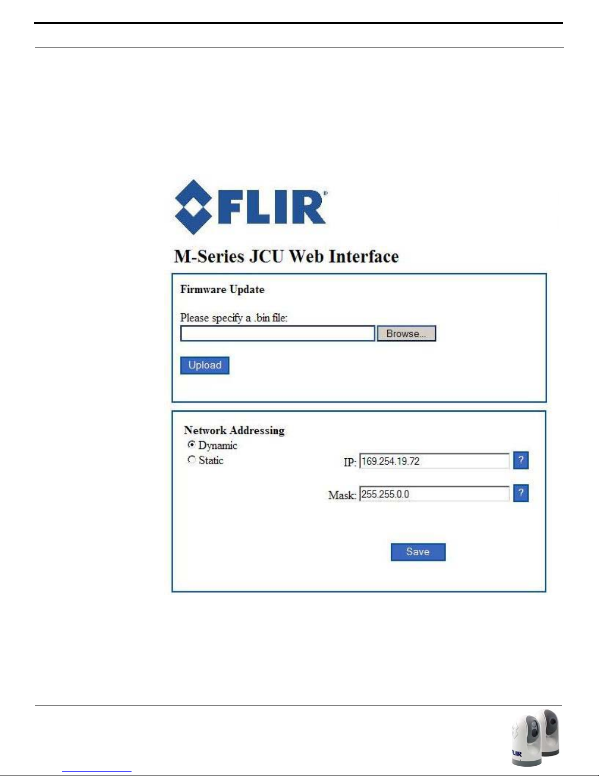
Network Settings
Note: As software updates
become available in the future,
the Firmware Update function
will be used to load the update
to the camera. Contact the
FLIR dealer where you purchased the camera for additional information, or contact
FLIR directly:
+1.888.747.3547.
JCU Control
The JCU web page allows the user to select the dynamic or static IP
address option for the JCU. It is similar to the IP Address option described
above for the camera. Note that a PoE power injector is necessary to connect a JCU to a PC. It is not possible to configure a JCU if it is not powered..
60 432-0003-00-10 rev 140 M-Series Operator’s Manual
Page 59

Custom Network Applications
Custom Network Applications
Programmers/Integrators
In more advanced/sophisticated installations, where other devices such as
radars may be present on the network, the use of a PC allows more complicated configuration, flexibility and customization. This interface is primarily
intended to give installers, dealers or even system integrators direct access
to low-level configuration options and to the actual network commands as
they are being processed.
For specialized applications, FLIR offers the Nexus Software Developers Kit
(SDK) that allows a marine electronics integrator to write custom software
programs based on the Nexus communication protocol. The SDK is a tool
that helps integrators deploy FLIR M-Series thermal imaging cameras and
other marine electronics such as radar in advanced networks. The SDK will
accelerate any application programming with FLIR Systems thermal imaging
cameras and will allow integrators to combine camera functionality with
other sensors and detection devices to take full advantage of this advanced
technology.
The SDK is available for download at no charge from the FLIR Network Systems website. The SDK helps software developers create SDK based applications that make use of the rich features in the Nexus application. The
SDK provides a step-by-step guide for the creation of applications to control
the pan/tilt motion of cameras, individual camera settings (zoom, gain control, etc), and many other powerful features that will allow integration of
Nexus enabled cameras into on-board control systems.
Interested parties may download the SDK at http://ns.flir.com/ under the
FLIR Developers Network tab. A new user must register as a developer
before access to the SDK is possible. The registration link is on the website
and an account is required for downloading any files. Optional software support packages may be purchased at the same location. Contact your FLIR
dealer where you purchased the camera for additional information, or contact FLIR directly: +1.888.747.3547.
Command Strings
For programmers and integrators, the actual command strings that are
sent back and forth with the camera are displayed in the Command Strings
fields at the bottom of the M-Series Web Control web page. The transmitted
commands are displayed in the TX field and the received commands are displayed in the RX field.
The commands sent back and forth are part of a communication protocol
known as the FLIR Network Application Programming Interface (API) protocol. For custom network applications, this protocol can be used by software
432-0003-00-10 rev 140 M-Series Operator’s Manual 61
Page 60

Custom Network Applications
developers to integrate a FLIR camera with other marine electronic devices
and other software applications.
In the future, the TX/RX fields on the Web Control web page will allow
developers who are testing new applications the ability to edit/modify the
commands on the fly to actually control the camera.
Resources Available
If you would like more information about thermal imaging cameras and
about integrating FLIR products with other marine electronics, please visit
our website or call to speak with an Applications expert, using the contact
information available on the back cover of this document.
Training
If you are interested in learning about thermal imaging cameras and how to
become a FLIR Certified Maritime Integrator (FCSMI), FLIR offers complimentary training courses at the Infrared Training Center:
http://www.flir.com/training
62 432-0003-00-10 rev 140 M-Series Operator’s Manual
Page 61
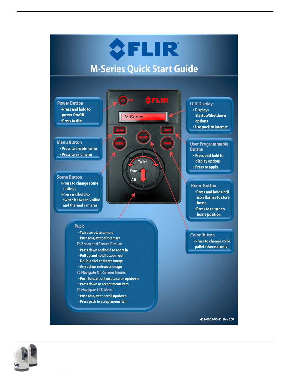
432-0003-00-10 rev 140 M-Series Operator’s Manual 63
Page 62

64 432-0003-00-10 rev 140 M-Series Operator’s Manual
Page 63

NOTES
432-0003-00-10 rev 140 M-Series Operator’s Manual 65
Page 64

FLIR Systems, Inc.
CS World Headquarters
FLIR Systems, Inc.
70 Castilian Dr.
Goleta, CA 93117
USA
PH:+ 1 877 773 3547
PH:+ 1 805 964 9797
FX: + 1 805 685 2711
sales@flir.com
EUROPE
CS Eurasian Headquarters
FLIR Systems CVS BV
Charles Petitweg 21
4847 NW Teteringen - Breda
Netherlands
PH: + 31 (0) 765 79 41 94
FX: + 31 (0) 765 79 41 99
flir@flir.com
FLIR Systems, Inc.
Corporate Headquarters
FLIR Systems, Inc.
27700A SW Parkway Ave.
Wilsonville, OR 97070
USA
PH: + 1 877 773 3547
FX: + 1 503 498 3904
sales@flir.com
 Loading...