

Page 1
Operator’s
Manual
M400
Page 2

© 2015 FLIR Systems, Inc. All rights reserved worldwide. No parts of this manual, in whole or in part, may be
copied, photocopied, translated, or transmitted to any electronic medium or machine readable form without the
prior written permission of FLIR Systems, Inc.Names and marks appearing on the products herein are either
registered trademarks or trademarks of FLIR Systems, Inc. and/or its subsidiaries. All other trademarks, trade
names, or company names referenced herein are used for identification only and are the property of their
respective owners.
This product is protected by patents, design patents, patents pending, or design patents pending.
The contents of this document are subject to change.
FLIR Systems, Inc.
6769 Hollister Ave.
Goleta, CA 93117
Phone: 888.747.FLIR (888.747.3547)
International: +1.805.964.9797
maritimecamerasupport@flir.com
Proper Disposal of Electrical and Electronic Equipment (EEE)
The European Union (EU) has enacted Waste Electrical and Electronic Equipment Directive
2002/96/EC (WEEE), which aims to prevent EEE waste from arising; to encourage reuse,
recycling, and recovery of EEE waste; and to promote environmental responsibility.
In accordance with these regulations, all EEE products labeled with the “crossed out wheeled
bin” either on the product itself or in the product literature must not be disposed of in regular
rubbish bins, mixed with regular household or other commercial waste, or by other regular
municipal waste collection means. Instead, and in order to prevent possible harm to the
environment or human health, all EEE products (including any cables that came with the product) should be
responsibly discarded or recycled.
To identify a responsible disposal method where you live, please contact your local waste collection or recycling
service, your original place of purchase or product supplier, or the responsible government authority in your area.
Business users should contact their supplier or refer to their purchase contract.
Document History
Version Date Comment
!00 December 2015
432-0012-00-10 Version 100 December 2015 2
Page 3

Contents
M400 Overview
General Information..............................................................................7
Additional References ....................................................................7
Documentation Conventions ..........................................................8
Warnings and Cautions ........................................................................8
System Description ..............................................................................9
Standard Features ..........................................................................9
M400 Components: ......................................................................10
Multiple Cameras, Joysticks, and Other Devices: ........................10
Thermal Video Display .......................................................................11
Video Screen Icons ......................................................................11
Position indicator icons...........................................................12
Scene type icons ...................................................................12
Active Camera Icons ..............................................................12
On-Screen-Display (OSD) Menu ............................................12
M400 System Startup
System Startup and Shutdown ...........................................................13
Park Mode ..........................................................................................13
The Bootup Process...........................................................................13
Powering the Camera...................................................................13
Powering the JCU II......................................................................14
JCU II Power Menu ............................................................................15
Standby States..............................................................................15
M400 Joystick Control Unit
Introduction.........................................................................................16
JCU II Buttons ....................................................................................16
Power Button ..........................................................................16
Menu Button ...........................................................................16
Scene Button—IR imaging only..............................................17
Color Button—IR Imaging only ...............................................17
Home Button...........................................................................17
Focus Buttons.........................................................................18
Camera Button .......................................................................18
User Buttons...........................................................................18
432-0012-00-10 Version 100 December 2015 3
Page 4

Contents
Display Camera and JCU II IP Address..................................18
JCU II Joystick....................................................................................18
Tilting the Camera ........................................................................18
Rotating the Camera ....................................................................19
Zooming the Camera....................................................................19
Button Summary...........................................................................19
M400 System Configuration
Overview ............................................................................................20
Main Menu..........................................................................................20
Park camera: ..........................................................................21
InstAlert/Exit InstAlert mode: ..................................................21
IceAlert/Exit IceAlert mode: ....................................................21
Surveillance: ...........................................................................22
Surveillance settings… ...........................................................22
Scan Width: ............................................................................22
Scan Speed: ...........................................................................22
NMEA: ....................................................................................22
Spotlight:.................................................................................23
Image settings... .....................................................................23
Help….....................................................................................23
Set-up… .................................................................................23
About…...................................................................................23
Image Settings Menu .........................................................................23
Polarity—IR camera only:.......................................................23
Stabilization: ...........................................................................24
Mirrored view: On/Off .............................................................24
Autofocus:...............................................................................24
Display icons: .........................................................................24
Help text: ................................................................................24
Color: ......................................................................................24
Icon & text color:.....................................................................25
VIS low light mode:.................................................................25
Set-up Menu.......................................................................................25
Save current settings as start-up defaults: .............................25
Restore settings from defaults:...............................................25
User interface preferences…..................................................25
NMEA settings… ....................................................................25
InstAlert highlight: ...................................................................25
IceAlert highlight: ....................................................................25
Visible Camera Low Light mode:............................................25
Calibration & diagnostics… ....................................................26
Manual FFC............................................................................26
IR Test Pattern: ......................................................................26
Activate Spotlight Demo: ........................................................26
Activate Pan and Tilt Pattern: .................................................26
432-0012-00-10 Version 100 December 2015 4
Page 5

Contents
Reset IR Lens:........................................................................26
Set Az & El zero reference: ....................................................26
User Interface Preferences Menu.................................................27
Joystick mode:........................................................................27
User button 1:
User button 2:
User button 3: .........................................................................27
IR/Daylight zoom lock:............................................................27
IR digital zoom:.......................................................................27
VIS digital zoom:.....................................................................27
NMEA Data.........................................................................................27
NMEA Settings .............................................................................29
Radar cursor (RSD):...............................................................29
Next Waypoint (BWC): ...........................................................29
Radar target (TTM):................................................................29
IP Interface and PC Operations
M400 Web Browser Interface.............................................................30
View Camera and JCU II IP Address ...........................................31
Camera Web Server Login Accounts ...........................................31
Log in to the Camera Web Page ..................................................31
Setup and Configuration Menus...................................................36
Setup->IR->ROI (region of interest) .......................................36
Setup->IR->AGC Scene Presets............................................37
Setup->Pan and Tilt->Status ..................................................37
Setup->Surveillance->Scan List .............................................38
Setup->Surveillance->Auto Scan ...........................................38
Setup->OSD ...........................................................................39
Maintenance Menus .....................................................................40
Maintenance->Server->Server Status ....................................41
Changing the IP Address of the Camera................................41
Maintenance->Server->LAN Settings.....................................41
Maintenance->Server->Security Functions ............................42
Maintenance->Sensor->Devices->Pan & Tilt .........................44
Changing Video Outputs ..............................................................46
Maintenance->Sensor->Devices ............................................46
Maintenance->Sensor->Devices->Video Matrix .....................46
Maintenance->Sensor->Modules->Video ...............................47
Maintenance->Sensor->Modules->Radar Interface ...............48
Geo-Referencing of the Sensors ..................................................49
Maintenance->Sensor->Modules->Georeference ..................49
Firmware Update ..........................................................................50
Maintenance->Files->Firmware..............................................50
Accessing the JCU II Web Interface.............................................50
432-0012-00-10 Version 100 December 2015 5
Page 6

Contents
Changing the IP Address of the JCU II...................................50
Enabling Universal Plug and Play (UPnP) .........................................51
UPnP Overview ............................................................................51
Enabling the UPnP User Interface................................................52
M400 Reference Information
Introduction.........................................................................................53
Acronyms ...........................................................................................53
List of Icons ........................................................................................54
System Specifications ........................................................................57
Troubleshooting Tips ..........................................................................57
Video not displayed on monitor ..............................................57
Cleaning .................................................................................58
Video not switching between thermal and visible ...................58
Noisy image............................................................................58
Image too dark or too light......................................................59
Performance varies with time of day ......................................59
Eastern or Western exposure.................................................59
Multiple Cameras and/or JCU IIs on a single network............59
432-0012-00-10 Version 100 December 2015 6
Page 7
1
M400 Overview
Ge n e r a l I n f o r m a t i o n
This manual describes the operation of the M400 cameras. If you need help or have additional
questions, please call to speak with our support experts; refer to the phone numbers listed on the
back cover of this manual.
This manual includes information about the following topics:
• System description
• Using the Joystick
• System startup and shutdown
• Using the on-screen-display (OSD) menus for controlling the M400
• Setting up and configuring the interface between the M400 and a PC
• Helpful reference information such as acronyms, parts lists, a table of icons, and a comparison
of model features
Additional References
The M400 system comes with a complete documentation set, available on the FLIR website, that
includes this manual as well as others. All documents are in PDF format and can be viewed with
Adobe Acrobat Reader:
• M400 Installation Guide (FLIR Doc. # 432-0012-00-12) contains information about how to
install the camera.
• M400 Quick Start Guide (FLIR Doc. # 432-0012-00-11) is a double-sided card that shows the
functions executed by the various joystick buttons.
Refer to the FLIR Resources Web page for up-to-date documentation:
http://www.flir.com/
432-0012-00-10 Version 100 December 2015 7
Page 8

Warnings and Cautions
Documentation Conventions
For safety, and to achieve the highest levels of performance from the M400 system, always follow
the warnings and cautions in this manual when handling and operating the M400 system.
Warning: Warning notices are used to emphasize that hazardous voltages, currents,
temperatures, or other conditions that could cause personal injury or death exist with this
equipment, or may be associated with its use.
Caution: Caution notices are used where equipment might be damaged if care is not taken or an
operation might have an unexpected outcome.
Note: Notes call attention to information that is especially significant to understanding and
operating the equipment.
Warnings and Cautions
Warning: Do not use the M400 system as the primary navigation system. Use it in conjunction
with other navigation aids and a primary manual navigation system.
Warning: Ensure power is removed before accessing power wires during installation or removal of
system components. Damage to equipment or injury to personnel may result.
Warning: Use of insufficient wire gauge can result in fire.
Warning: The M400 system is not designed to operate in an enclosed environment in the
presence of flammable gases. Failure to follow this warning may result in explosion or fire.
Warning: The M400 camera body is a remotely and automatically controlled device. Ensure
camera motion has been disabled before cleaning surfaces that can cause pinch hazards.
Caution: Do not open the M400 unit for any reason. Disassembly of the M400
(including removal of the cover) can cause permanent damage and will void the warranty.
Caution: Be careful not to leave fingerprints on the M400 optics.
Caution: The M400 requires a power supply of 12 Vdc to 24 Vdc nominal, 5.5 A maximum @
24 Vdc, 11 A maximum @ 12 Vdc. Absolute voltage range: 12 Vdc to 32 Vdc. Operating the
system outside of the specified input voltage range or the specified operating temperature range
can cause permanent damage.
Operating temperature range –20 °C to +55 °C (–4 °F to +131 °F) per IEC 60945
Storage temperature range –50 °C to +80 °C (–58 °F to +176 °F)
432-0012-00-10 Version 100 December 2015 8
Page 9
System Description
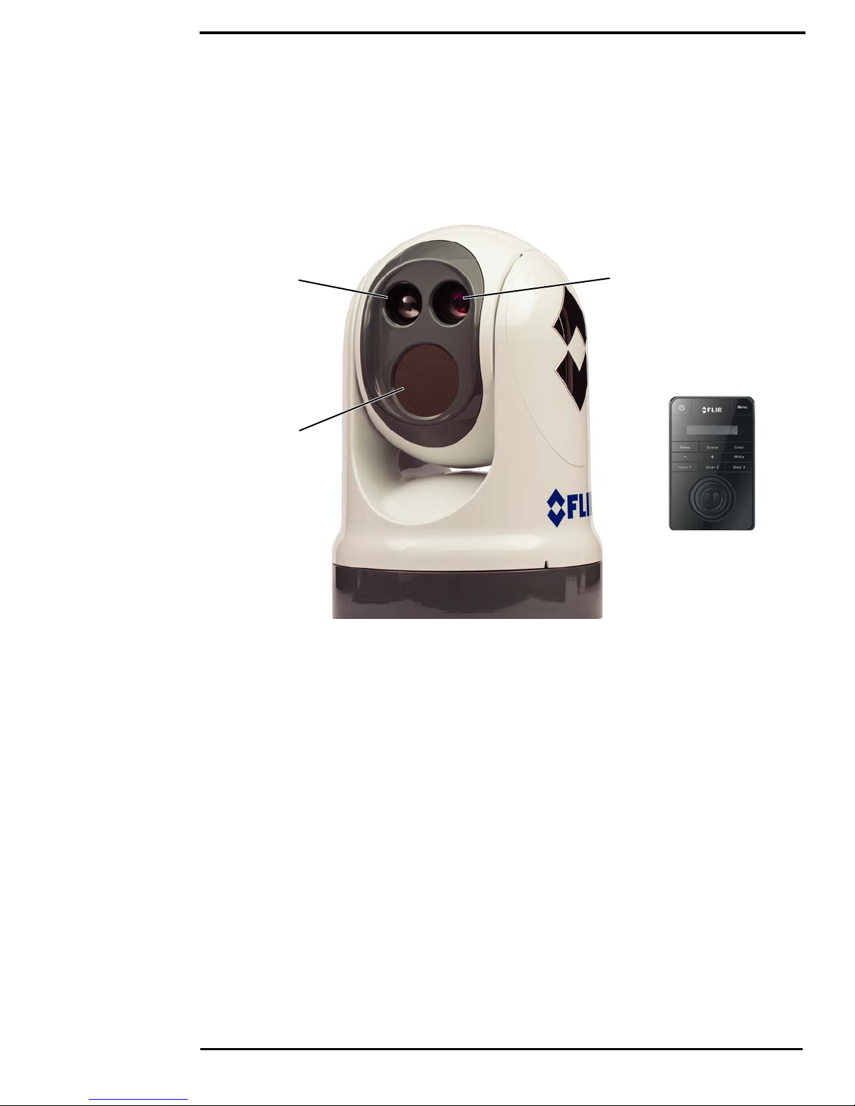
Figure 1-1: M400 Pan/Tilt Camera System
LED spotlight
Thermal camera
HD visible-light camera
Joystick Control Unit
(JCU II)
System Description
The multi-sensor M400 is a stabilized maritime thermal and high definition (HD) visible-light
camera system for use on most types of vessels. The long wave infrared (LWIR) thermal camera
provides excellent nighttime visibility and situational awareness, without any form of natural or
artificial illumination. The HD visible-light camera with 30X optical zoom provides daytime viewing.
Standard Features
• Thermal camera, 4x continuous optical zoom
• HD visible-light camera, 30x continuous optical zoom
• Active gyro-stabilization
• Radar integration to follow specific radar targets (NMEA 0183 serial communications)
• Dual, independent H.264 network video streams
• HD-SDI (Serial data interface)
• Analog video
The thermal camera, HD visible-light camera, and high intensity LED spotlight are aligned to view
or illuminate a target for quick identification providing enhanced navigational abilities in a variety of
conditions.
432-0012-00-10 Version 100 December 2015 9
Page 10

System Description
M400 Components:
• Main camera body, also known as the pan/tilt camera unit
• Joystick Control Unit (JCU II), compatible with the MU, MV, and M400 camera systems
• Ethernet switch with power over Ethernet (PoE) to power the JCU II and network to the camera
• Analog and/or digital video monitors (customer supplied)
• Personal computer (PC) to control and configure the system (customer supplied)
The M400 camera body and JCU II are network devices. In some installations, additional M400
cameras and/or additional JCU II may also be used.
The camera body’s pan/tilt mechanism allows the operator to rotate 360° in azimuth, tilt +/– 90° in
elevation. The camera body houses the two cameras and the LED spotlight.
The JCU II is the primary control for the camera. The JCU II is used to wake the system or put it in
standby, select the active camera, operate the pan and tilt movement of the camera, zoom the
active camera, control the M400 modes and features, and configure the system settings by means
of OSD menus.
The JCU II has various buttons, an LCD display, and the joystick. The joystick can be moved left
and right or forward and back, and rotated in either direction. “M400 Joystick Control Unit” on
page 16 describes the functions of the JCU II in detail.
The M400 uses on-screen icons to indicate the camera position (azimuth and elevation) and
various system settings that have been enabled. These symbols are introduced in “Thermal Video
Display” on page 11 and are further explained throughout this manual in the discussion of related
functions.
Multiple Cameras, Joysticks, and Other Devices:
More than one JCU II can be used to control the camera, and more than one display can be used
to view the video. A personal computer (PC) on the same network as the camera, can use a web
browser to view video, control, and configure the system. The camera’s web server uses password
protected accounts to control access to camera functions. Using a PC is described in “IP Interface
and PC Operations” on page 30.
Also, a single JCU II can be used to select and control more than one camera. In this case, a
menu on the JCU II lists available cameras. In the LCD display of the JCU II, the name of the
currently selected camera is displayed. When more than one JCU II is installed in the network, a
camera will respond to commands from any JCU II that has the camera selected.
Typically, a JCU II and a video monitor are mounted in close physical proximity, as a pair, so you
can immediately see the changes on the video screen when you use the JCU II to change the
camera position (pan or tilt).
Contact FLIR Systems, Inc. for more information regarding available accessories including PoE
equipment, video distribution amplifiers, cables, connectors, mounting hardware, etc. Contact
information is listed on the back of this manual.
432-0012-00-10 Version 100 December 2015 10
Page 11
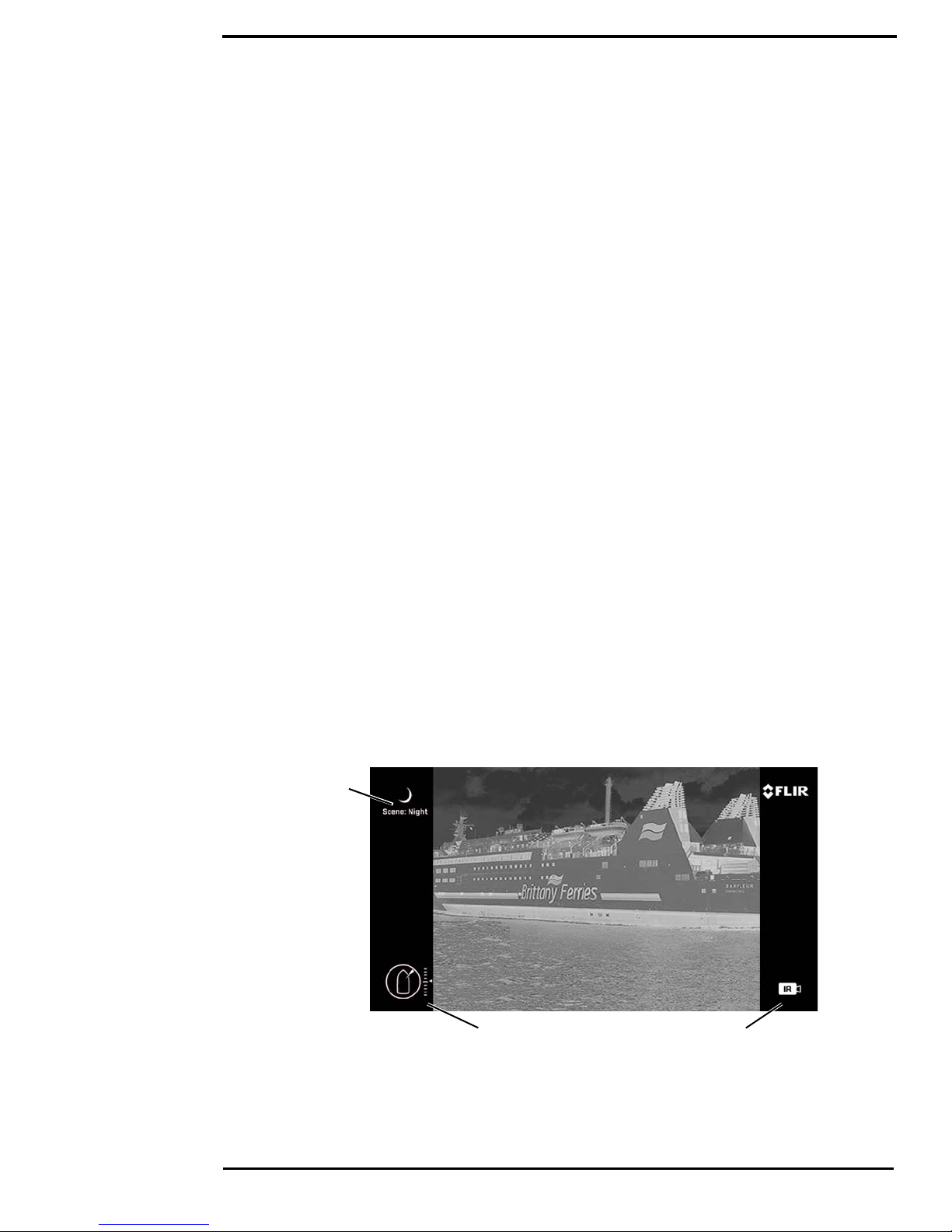
Thermal Video Display
Active CameraPosition indicators
Scene type
Figure 1-2: On-screen Icons
Thermal Video Display
The infrared (IR) imaging thermal camera relies on the fact that all objects, even very cold objects
like ice, emit thermal energy in the portion of the infrared spectrum that the camera can see.
Therefore, unlike an illuminated infrared camera, the thermal imaging camera does not need an
additional active illumination source and images are based on directly radiated energy rather than
reflected energy.
When the thermal camera is in white-hot mode, the warm objects in the scene are shown as white,
or lighter shades of gray, and cold objects are shown as black or darker shades of gray. When the
video polarity is switched, this is reversed.
This is why hot objects such as parts on a running outboard motor appear white (or black or red
depending on the video image mode selected), while the water or other cold objects appear dark
(or cool). Scenes with familiar objects will be easy to interpret with some experience. The camera
automatically optimizes the image to provide the best contrast in most conditions.
FLIR Systems, Inc. offers a comprehensive selection of training courses to help you to get the best
performance and value from your thermal camera. Find out more at the FLIR training Web page:
http://www.flir.com/training
Video Screen Icons
Depending on the system settings, various symbols are shown on the screen. Some of these icons
are always shown on the screen, and some appear momentarily or only when certain functions are
enabled or executed. The icons can be shown as white or red. See “Display icons:” on page 24 for
a description of menu options and the displayed icons.
The following figures illustrate some of the icons displayed by the system, as well as an example
of the OSD menu that is shown when the Menu button is pressed. Using the menus is described in
“M400 System Configuration” on page 20.
A complete list of all of the icons used in the system and a brief description of how they are used
can be found in “List of Icons” on page 54.
432-0012-00-10 Version 100 December 2015 11
Page 12

Thermal Video Display
Azimuth Elevation
Night Harbor
Day Contrast
Thermal Visible
Figure 1-3: OSD Menu
Position indicator icons
The azimuth position indicator shows the direction the camera is
pointing relative to the vessel. The shaded triangle shows the
approximate camera field of view (FOV).
The elevation position indicator shows the vertical tilt of the
camera above or below the horizontal plane of the vessel.
Scene type icons
The Scene button on the JCU II cycles through four preset
automatic gain control (AGC) settings, which change the image
brightness and contrast settings. Regardless of the scene setting,
the thermal camera automatically adjusts to the scene to provide a
balanced, high-quality image. However, you may prefer an image
that has more or less contrast than the default one provided, and
the Scene button provides that type of fine adjustment.
Active Camera Icons
At any given time, either the thermal camera (IR) or the HD
visible-light camera is designated as the Active camera. The Active
camera responds to commands such as zoom or focus that could
apply to either camera. Pressing the CAMERA button on the
JCU II toggles the active camera between the thermal camera and
the HD visible-light camera.
On-Screen-Display (OSD) Menu
The OSD menu appears when the Menu button on the JCU II is pressed. Menu entries are
selected using the joystick and the joystick buttons. Pressing the Menu button again removes the
menu from the screen. The OSD menu can also be accessed from a networked PC through the
Web Browser Interface. Refer to “Function Keys” on page 35.
432-0012-00-10 Version 100 December 2015 12
Page 13

2
M400 System Startup
System Startup and Shutdown
The M400 camera does not have an on/off switch. Instead, its power state is controlled by the
JCU II. Generally, the camera is never completely off but in a Park mode or standby state waiting
for a “wake” command from the JCU II.
Typically, the M400 system is connected to power through a circuit breaker, which functions as the
primary on/off switch for the system. Should it be necessary for some reason to completely shut
down the system, the circuit breaker is used. In normal operation, however, the camera will have
power and will be in one of four states or modes:
• Bootup, or powering on
• Powered on and fully functional
• Park mode, powered on with video turned off
• Standby, a low-power state waiting for a wake command
Park Mode
When the system is in Park mode, the camera does not generate a live video signal. After the
bootup is complete or when done using the system, Park the camera from the OSD menu to keep
the system ready to use at a moments notice.
The Bootup Process
The bootup process is slightly different depending on whether the system had been completely
turned off or is being wakened from a standby state. Most of what happens, however, is the same.
Powering the Camera
During bootup, a series of screens are shown as various components are activated. How the
screen looks will vary depending on the particular configuration settings of your installation. In
general, the following sequence occurs:
1. If starting from a full shutdown, make sure the monitor is turned on, then power on the system.
2. The FLIR splash screen is shown, then live video with a counter showing boot progress.
3. When the bootup is complete (about 4 minutes), the monitor shows icons, live video, and the
OSD menus are enabled.
432-0012-00-10 Version 100 December 2015 13
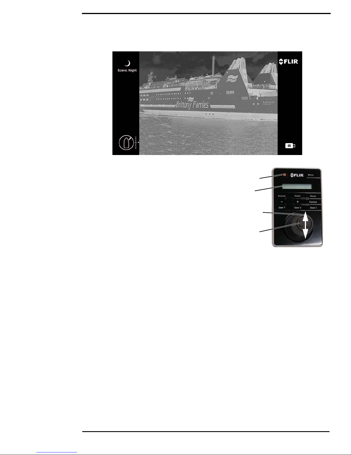
Page 14
The Bootup Process
Power
LCD
screen
Select
camera
Scroll up
or down
Powering the JCU II
When the JCU II is receiving power, the Power button will
be lit amber. When the button is pressed for
approximately three seconds, the JCU II will turn on and
search for cameras on the network.
On the LCD screen, Starting, then Searching… is
shown. When a camera is found, the message changes
to Connecting…, which continues to flash until the
connection process completes and is replaced by the
camera ID, such as M400. When more than one camera
is found on the network, the JCU II attempts to reconnect
to the last camera it was connected to, or if it has not
connected to a camera, it will prompt the user to select a
camera.
Important: Fully establishing a connection may take up to three minutes. Please be patient while
the system verifies each component.
432-0012-00-10 Version 100 December 2015 14
Page 15
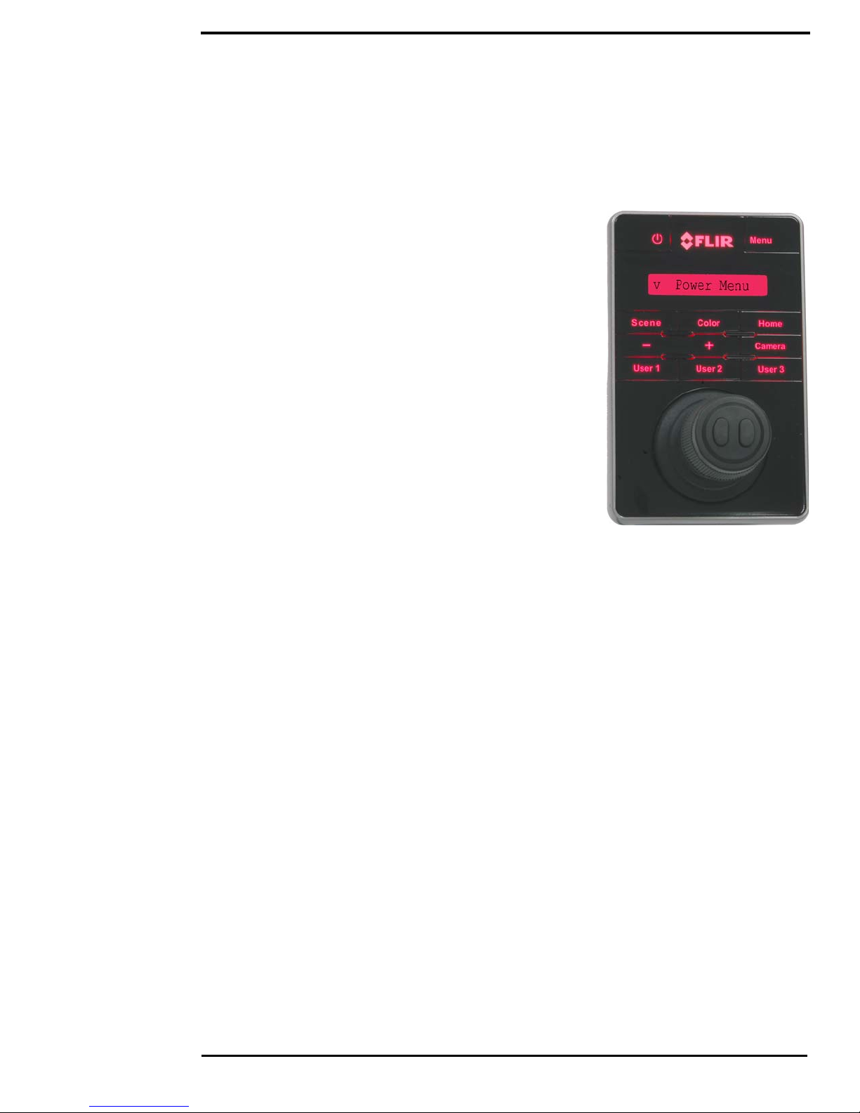
JCU II Power Menu
JCU II Power Menu
The JCU II LCD screen generally shows the ID of the camera that is connected to the JCU II. The
various functions are accessed from a set of menus, with each menu entry selectable in the JCU II
display. When powered on and connected to a camera, pressing and holding the Power button
causes the JCU II to enter the Power Menu.
Use the JCU II joystick to scroll up and down within the menus
(push fore and aft), and select an entry by clicking the left
joystick button. When the JCU II is in the Power Menu mode,
the other JCU II buttons are disabled.
In the JCU II display, a down arrow (v) indicates you can access
additional menu choices by moving the joystick down. An up
arrow (^) indicates the last menu entry is displayed, and the
other choices must be accessed by moving the joystick up. A
double arrow indicates you can move up or down in the menu.
The Power Menu shows the following menu options:
Assign JCU?
JCU Stndby?
Camera Stndby?
System Stndby?
Global Stndby?
Calibrate JCU?
Cancel
Standby States
After you are done with the camera you can Park the camera from the OSD menu keeping the
system ready to use at a moments notice on a command from the JCU II. When the system is in
Park mode, the camera does not generate a live video signal.
To initiate other standby modes, press and hold the Power button. After a brief countdown, the
Power Menu is shown. Scroll down with the joystick, press the left joystick button to select an
option from the menu. The menu options available will reflect the available hardware on the
camera network.
• JCU Stndby?—select to power down the JCU II.
• Camera Stndby?—select to power down the camera, leaving the JCU II powered
to connect to a different camera.
• System Stndby?—select to power down the camera and the JCU II.
• Global Stndby?—select to power down all the cameras and all the JCU IIs present on the
network.
Troubleshooting Tip: If the JCU II does not have power, it may be connected to a Power over
Ethernet (PoE) switch that has not been powered on, or it may be connected to a network switch
that does not provide PoE power.
Troubleshooting Tip: If this is the first time the JCU II has been used to connect to the camera, or
if the camera was not powered before the JCU II, v Select Camera is shown on the LCD
screen. Scroll down with the joystick to select a camera to control. When the ID of the camera
appears, press the left joystick button to select it. The camera ID will blink momentarily to indicate
it has been selected.
432-0012-00-10 Version 100 December 2015 15
Page 16

3
Standby
Powered on
Power button
M400 Joystick Control Unit
Introduction
The Joystick Control Unit (JCU II) is the primary method of
controlling the M400 camera. Use it to move the camera, zoom the
camera, switch between infrared and visible-light cameras, adjust
the image settings, and access the on-screen menus.
This chapter describes how to use the JCU II buttons to operate the
camera features. Some of these features vary depending on the
specific way the system has been configured.
When specific settings affect a particular button, refer to the various
configuration settings and how they affect operation in Chapter 4,
"M400 System Configuration," on page 20.
Enabling different system modes can affect how the buttons work.
Table 3.1 on page 19 summarizes the actions for each button.
JCU II Buttons
All of the buttons on the JCU II perform multiple functions. In most cases, each performs one
function when it is pressed briefly (short press) and a different function when it is pressed and held
(long press). The descriptions of the buttons in this section assume that the JCU II is powered on
(not in standby).
Power Button
Short Press—When the JCU II is powered on, a short
press of the Power button cycles through the four levels of
brightness (including off) for the JCU II display. The JCU II
controls are back lit to make them easier to see at night.
Use this button to adjust the brightness of the back lighting.
Long Press—When the JCU II is in standby, pressing and
holding the Power button is used to “wake up” the camera.
When the JCU II is powered on, it is used to access the
JCU II Power Menu to perform functions such as selecting
another camera or placing the system in standby. Refer to
“JCU II Power Menu” on page 15.
Menu Button
Press the Menu button to access the system on-screendisplay (OSD) menus. In most cases, there is no need to
modify the factory default configuration settings of the
system. Refer to “M400 System Configuration” on page 20.
432-0012-00-10 Version 100 December 2015 16
Page 17
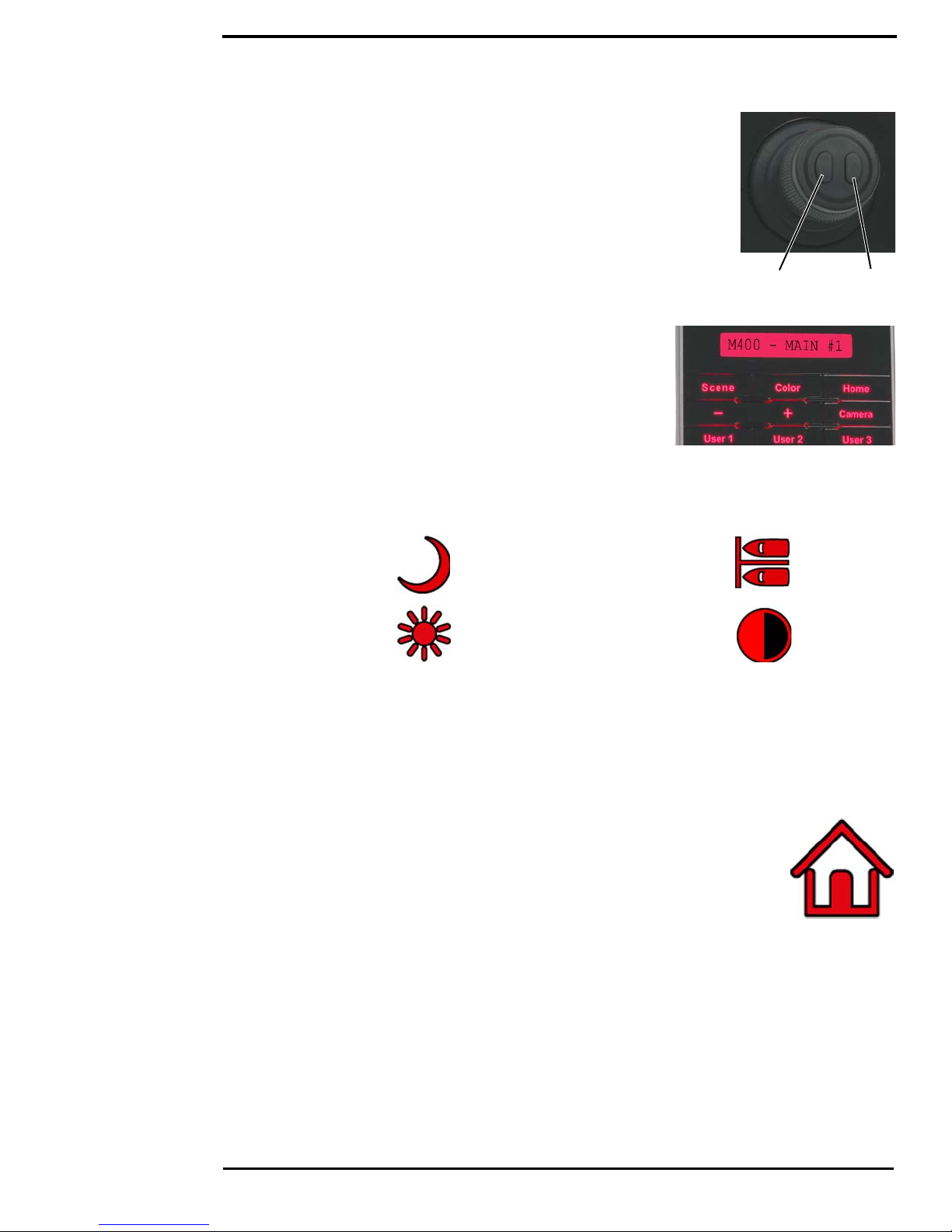
JCU II Buttons
Back Select
When the OSD menu is shown, use the joystick up, down, left, and right to
navigate through the menu entries. The buttons on top of the joystick are
used as select and back buttons.
• Joystick Up – move up in a vertical menu
• Joystick Down – move down in a vertical menu
• Joystick Right/Left – move to the next menu or menu choice
• Menu – Exit Menu
Scene Button—IR imaging only
The M400 thermal sensor automatically adjusts to changing
conditions providing optimized high-contrast images. The preset
automatic gain control (AGC) settings offer the most balance
and image quality for specific conditions. Experiment with the
different settings to find out which settings work best in different
conditions. The Scene button only effects the IR camera.
Short Press—A short press of the Scene button cycles through
the four preset AGC settings, which change the image gain and
level settings. The icon for each scene preset is shown on the
video monitor display.
Night
Day Contrast
Harbor
Color Button—IR Imaging only
Short Press—Pressing the Color button cycles through the preset color palettes of the active IR
camera. See “Color:” on page 24 for these additional options.
Long Press—Press and hold the Color button to invert the thermal camera video polarity (for
example, changing from black-hot to white-hot).
Home Button
Short Press—A short press of the Home button moves the camera to its home
position. The home position is a programmable preset position that operators can
use as a reference. When the Home button is pressed, the home icon appears
briefly on the video monitor display.
Long Press—Pressing and holding the Home button sets the home position.
First use the joystick to point the camera’s line of sight to the a new home position. Press and hold
the Home button until the home symbol flashes on the video monitor display; the new home
position is set.
432-0012-00-10 Version 100 December 2015 17
Page 18
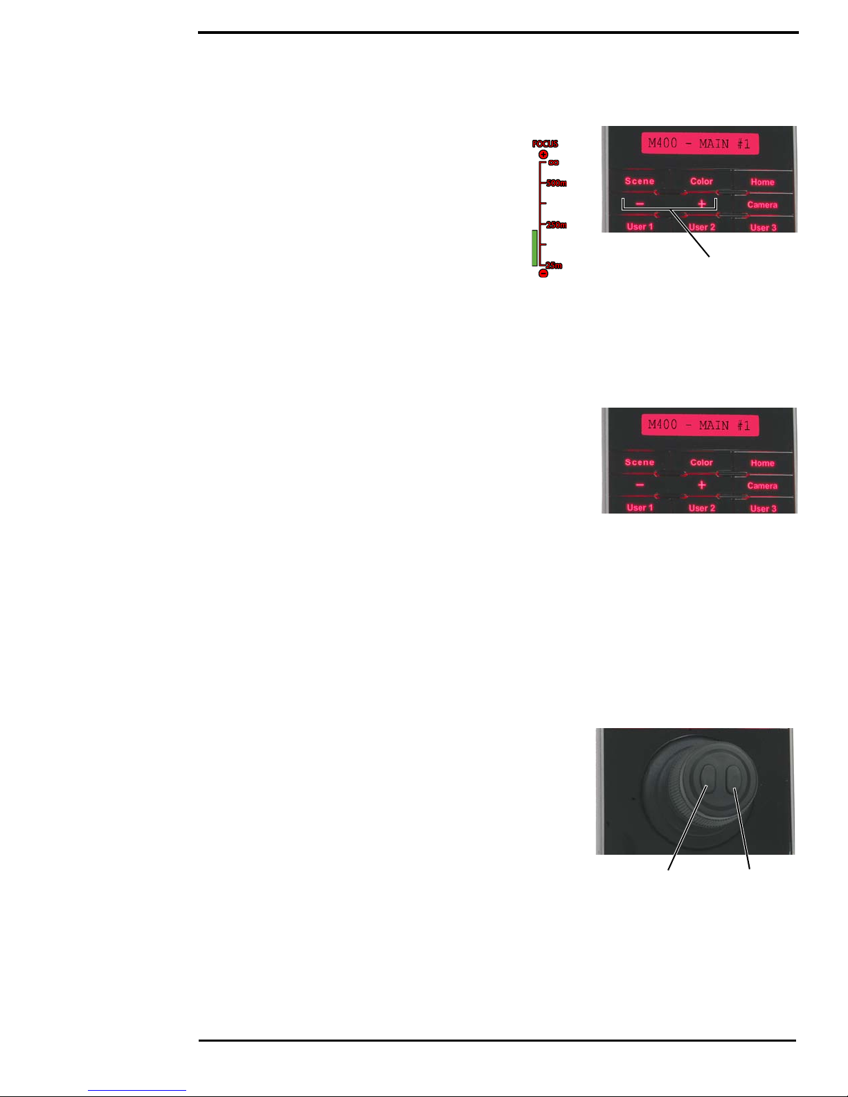
JCU II Joystick
Manual focus
buttons
Back Select
Focus Buttons
The M400 thermal camera can be focused either
manually or automatically. The visible-light camera
is always focused automatically.
The manual focus buttons are effective only when
the IR camera is the Active Camera.
the – button will move the focus nearer
the + button will move the focus farther away
During the manual focus operation, the OSD focus
bar will change accordingly.
Camera Button
Switch the Active Camera shown on the main video output. The buttons on the JCU II are effective
only on the Active Camera, except as noted.
User Buttons
The User buttons are programmable one-touch buttons that
quickly access the most often used settings or functions.
Configure the short-press action of this button from the User
Programmable Button menu entry (see page 27).
Default User Button Settings:
• User 1 – Auto Focus
• User 2 – Stabilization on/off
• User 3 – Spotlight
Display Camera and JCU II IP Address
Press the Color button while pushing the joystick forward; the IP address of the JCU II and then
the camera will display on the JCU II screen.
JCU II Joystick
The JCU II joystick and can be moved left or right, forward and
back, and twisted in either direction. The joystick movement is
translated to control the pan/tilt position of the camera and the
zoom setting.
Note: The joystick uses proportional control; therefore, the
farther it is rotated or directed from center, the faster the
camera will move.
Tilting the Camera
The camera has two tilt modes: Gaming and Pilot. When in Gaming mode (the default), moving
the joystick forward causes the camera to tilt up; moving the joystick back causes the camera to tilt
down.
432-0012-00-10 Version 100 December 2015 18
Page 19

JCU II Joystick
When in Pilot mode, moving the joystick forward causes the camera to tilt down; moving the
joystick back causes the camera to tilt up.
See “User Interface Preferences Menu” on page 27 for details about this settings.
Rotating the Camera
Use the joystick to rotate the camera to the left and right. Push the joystick to the right and the
M400 will pivot to the right. Push the joystick to the left and the M400 will pivot left.
Zooming the Camera
Twisting the joystick causes the camera to zoom in (clockwise) or zoom out (counterclockwise).
Button Summary
Table 3.1 summarizes the action of each button on the JCU II.
TABLE 3.1 Summary of Button Actions
Button Action
Color Short Cycle through the thermal palette options of the IR thermal imaging
sensor.
Power Short
Power Long
Home Short Return to home position
Home Long Set home to current position
Menu Short Display or exit menus
Scene Short Cycle through four preset scene settings
User 1 Auto Focus (can be reprogrammed)
User 2 Vertical Stabilization on/off (can be reprogrammed)
User 3 Spotlight on/off (can be reprogrammed)
Color + Joystick Forward Display JCU II and camera system IP address
Change JCU II back light illumination level
Display JCU II Power Menu
432-0012-00-10 Version 100 December 2015 19
Page 20

4
Figure 4-1: OSD Main Menu
Active menu item
Press right joystick button to select Additional menu items
End of menu symbol
Menu will loop to
the other end
M400 System Configuration
Overview
This chapter describes how to configure the system options using on-screen-display (OSD)
menus. Operating the M400 camera does not require modifying any of the factory configuration
settings. However, the OSD menus allow setting the following:
• Choose configuration options that match personal preferences such as Joystick Mode or the
default color scheme.
• Enable or disable specialized modes such as InstAlert, IceAlert, NMEA messaging, or
operating the camera in Surveillance mode.
After making updates, most of the changes persist. However, a few settings revert to the factory
default when the system is rebooted.
Not all options can be used at the same time. The way the various options interact is also
described in the following sections.
Some configuration settings are changed directly by pressing a button on the JCU II. These are
described in “JCU II Buttons” on page 16. The way some of the buttons work can be modified
using OSD menus, described in this chapter.
Main Menu
Use the Menu button to turn the OSD menu on or off. When the OSD menu is shown, the joystick
is used to navigate through the menus and select various menu entries.
432-0012-00-10 Version 100 December 2015 20
Page 21

Main Menu
Back Select
Use the joystick to navigate through the menus and select options.
Press the Menu button to exit the menus.
Note: During navigation in the OSD menu, camera zoom is disabled,
but manual focus/Auto focus is still enabled.
Some features are directly accessible from the main menu. Selecting a
menu button below invokes the action immediately and closes the
OSD menu.
Park camera: the camera drives to its predefined Park position and remains fully active (no
Stand-by) except that the video is turned off. To exit Park position and return to normal operation,
press the Home button. The camera will then return to Home position. The Park position can be
reconfigured by an admin user through the web browser interface. See “M400 Web Browser
Interface” on page 30.
InstAlert/Exit InstAlert mode: When the camera is placed in InstAlert mode, a special
search palette is invoked so that a set percentage of the hottest temperatures in the image are
highlighted in Red-Orange shades, while colder temperatures are all in shades of gray. Especially
useful for locating people or running boats in the dark. After invoking the mode, pressing the Menu
button will show the InstAlert settings menu. The Highlight setting controls the percentage of the
hottest temperatures to display in Red-Orange.
IceAlert/Exit IceAlert mode: Conversely to InstAlert mode, when the camera is placed in
IceAlert mode, a special search palette is invoked so that a set percentage of the coldest
temperatures in the image are highlighted in Blue-Green shades, while warmer temperatures are
all in shades of gray. Especially useful for locating ice in the dark. After invoking the mode,
pressing the Menu button will show the IceAlert settings menu. The Highlight setting controls the
percentage of the coldest temperatures to display in Blue-Green.
432-0012-00-10 Version 100 December 2015 21
Page 22

Main Menu
Surveillance: When the camera is in surveillance mode, it pans continuously left and right,
until it is taken out of surveillance mode or until the JCU II is used to move the camera. The
camera does not automatically resume panning; enable surveillance again by pressing a User
button (if it is programmed to enable this mode) or selecting it in the main menu.
Surveillance settings… When Surveillance settings is selected from the Setup menu or the
Menu button on the JCU II is pressed when in Surveillance mode, the following OSD menu is
shown.
Scan Width: In surveillance mode, the Scan Width determines the range of horizontal azimuth
(pan) covered by each scan. The choices are:
Custom: The camera scans from approximately 20
o
(40
total).
Small: The camera scans from approximately 20
o
(40
total).
Medium: The camera scans from approximately 40
o
(80
total).
Large: The camera scan covers 80
o
(160
total). The default scan width is wide.
o
to the left and right of center
o
left and right of center
o
left and right of center
o
left and right of center
Note: The center of the scan pattern is determined by the direction the camera is pointing when
surveillance is enabled. The scan pattern is not centered about the home position, unless the
camera is in the home position when surveillance is enabled.
Scan Speed: In surveillance mode, the scan speed determines how quickly the camera scans
back and forth. The choices are fast, medium, and slow.
The scan speed is affected by the zoom state (if the camera is zoomed in, it scans at a slower
rate). The default scan speed is slow; try all three settings to determine which is best for any
situation.
NMEA: Select this option to enable or disable the processing of messages using the NMEA
interface. The factory default setting is disabled. All messages are ignored when NMEA Mode is
disabled even if the specific message types are enabled. See “NMEA Settings” on page 29.
432-0012-00-10 Version 100 December 2015 22
Page 23

Image Settings Menu
End of menu symbol
Menu will loop to
the other end
The following main menu buttons provide additional choices for system settings and information.
Spotlight: Select this option and then select one of the active spotlight modes (On, Flash,
SOS). The Spotlight turns on in the selected mode. If a user programmable button (UPB) is
programmed as Spotlight, use it to turn the spotlight On/Off in the selected mode.
Image settings... See “Image Settings Menu” on page 23.
Help… Refer to the help menus for camera operation information.
Set-up… See “Set-up Menu” on page 25.
About…
Image Settings Menu
When Image settings is selected from the main menu, the following OSD menu items are shown.
Polarity—IR camera only: Inverts the colors representing hot
and cold in the infrared imagery. When using the IR camera the color
palettes described below are available. Inverting the polarity reverses
the color map of the thermal image.
Color Palette Polarity Inverted
Grayscale White-hot Black-hot
Redscale Red-hot Red-cold
Fusion Light-hot Dark-hot
432-0012-00-10 Version 100 December 2015 23
Page 24

Image Settings Menu
Stabilization: Select this option to enable or disable the two-axis
mechanical gyro stabilization, which prevents camera images from
being affected by waves and ship motion. Gyro Stabilization is
automatically turned off when the camera in Park mode or in standby,
but the system restores the setting when the camera is returned to
service.
The horizontal (pan) stabilization can be turned off while retaining the vertical (tilt) stabilization.
This can be helpful if using the camera as an aide to navigation and keep it pointing in the same
position relative to the vessel as it turns.
Off
Vertical (point mode)
Horiz & vertical
Mirrored view: On/Off
Autofocus:
Display icons: Minimal, Custom, Full
Selecting Minimal turns off most of the on-screen icons except when
their corresponding controls are actively in use. The pan position
(azimuth) icon, tilt (elevation) position icon, and the FLIR logo are
always displayed. Other icons such as home and scene display on the
screen only momentarily when they are changed. Selecting Full
maximizes the display of the on-screen icons. Some icons such as
home are only displayed momentarily. Refer to“Setup->OSD” on
page 39 for configuring Custom.
Help text: On/Off
One or two lines of help text can be displayed at the bottom of the
screen to provide contextual help to the user. Unlike feedback or
notification text which is always shown, the help text is controlled by
this setting.
Color: Cycle through the available color palettes.
Grayscale
Redscale
Fusion
432-0012-00-10 Version 100 December 2015 24
Page 25

Set-up Menu
Icon & text color: Red/White
VIS low light mode: On/Off
Set-up Menu
When Setup is selected from the main menu, the following OSD menu
is shown.
Save current settings as start-up defaults: Select this option to store the current camera
settings described below for start-up or anytime Restore settings from defaults is selected.
Restore settings from defaults: Select this option to revert to the stored values of the
following settings.
Active Camera Scene Color
Home position Polarity Stabilization
Icon display Help text Mirrored View
Joystick mode UPB assignments NMEA auto movement settings
InstAlert settings IceAlert settings
User interface preferences… See “User Interface Preferences Menu” on page 27.
NMEA settings… See “NMEA Settings” on page 29.
InstAlert highlight: Set the percentage of the highest temperatures in a scene to be displayed
in Red/Orange. All other temperatures are shown in grayscale.
IceAlert highlight: Set the percentage of the lowest temperatures in a scene to be displayed
in Blue/Green. All other temperatures are shown in grayscale.
Visible Camera Low Light mode: Select between Auto and Manual operation.
432-0012-00-10 Version 100 December 2015 25
Page 26

Set-up Menu
Calibration & diagnostics…
Manual FFC This function applies to the IR camera only. When selected, the camera drives the
camera to a preset position and performs the FFC calibration (< 5 s). The camera then returns to
its Home position.
IR Test Pattern: On/Off)
Activate Spotlight Demo:
Activate Pan and Tilt Pattern:
Reset IR Lens:
Set Az & El zero reference: Icons on the video show the direction the camera is facing in
relation to an outline of a ship. The M400 camera has a “forward” direction adjustment which has
been set at the factory. After the camera is installed, both the azimuth and elevation should be set
to account for variations required during installation so that the icons on the video show the
expected angular position of the camera. The azimuth direction should be directly toward the front
of the vessel; the elevation may be set to the horizon or another user preferred reference.
1. Using the JCU II, point the camera directly ahead and choose an elevation reference point.
For example, place the horizon in the center of the video.
2. Press the Menu button to turn the OSD menu on.
3. Navigate to Set-up Menu, Calibration & diagnostics…, then select Set Az & El zero
reference.
4. Select Set origin to set the azimuth and elevation offsets.
5. Verify that the icons on the video correspond to the direction the camera is pointing.
6. Check position settings for “Azimuth and Elevation Offsets” on page 44 and “Setting Park
Position” on page 45.
432-0012-00-10 Version 100 December 2015 26
Page 27

NMEA Data
User Interface Preferences Menu
Joystick mode: Gaming/Pilot) In managing the elevation (tilt) of the camera, the joystick can
be used in one of two modes.
Gaming Mode: Moving the joystick forward causes the camera to tilt up. Moving the joystick
back causes the camera to tilt down. This is the factory default mode.
Pilot Mode: Moving the joystick forward causes the camera to tilt down. Moving the joystick
back causes the camera to tilt up.
User button 1:
User button 2:
User button 3: The User buttons are programmable one-touch buttons on the JCU II that
quickly access common settings or functions. Use this menu to select a function to associate with
each User button from the following choices: Stabilization, Surveillance, Icon Levels, Spotlight on/
off, Invert polarity, InstAlert on/off, IceAlert on/off, Rearview on/off, Signal Light, Autofocus
IR/Daylight zoom lock: On/Off)
IR digital zoom: On/Off)
VIS digital zoom: On/Off)
NMEA Data
This section describes how to configure and use the set of NMEA interface functions supported by
the M400. The NMEA interface allows the M400 to communicate with radar, GPS, or other devices
using the National Marine Electronics Association (NMEA) 0183 protocol. NMEA 0183 (or NMEA
for short) is a combined electrical and data specification for communication between marine
electronic devices.
Additional information regarding the protocol can be found on the NMEA Web site:
http://www.nmea.org/content/nmea_standards/nmea_standards.asp.
When NMEA is being used, the M400 acts as a listener and receives messages from the main
control unit that is monitoring various sending devices in the system, such as radar, GPS, or
independent input ports. The M400 connects to the other equipment through the M400 Connection
box.
432-0012-00-10 Version 100 December 2015 27
Page 28

NMEA Data
The NMEA protocol allows the camera to automatically point toward vessels and other
objects that show up on the display and to track their movement.
three types of NMEA messages.
• Radar Cursor Tracking, which is implemented using the NMEA Radar System Data (RSD)
sentence format
• Slew to Waypoint, which uses the NMEA Bearing and Distance to Waypoint, Great Circle
(BWC) sentence format
• Radar Tracking, which uses the NMEA Tracked Target Message (TTM) sentence format
Even though you can only choose three types of messages to enable through the NMEA interface,
the M400 uses additional messages to perform the calculations needed to respond to these three.
If your system is not responding as expected, verify that the NMEA device sending messages is
sending the following additional message types:
• HDT Heading, True
• GGA Global Positioning System Fix Data
• VHW Water Speed and Heading
• OSD Own Ship Data
The M400 can receive
• TLL Target Latitude and Longitude
Any combination or all three messages can be enabled; when more than one type is enabled, the
system processes RSD first, then BWC, and finally TTM. For example, if the unit is listening to
BWC or TTM messages and looking at a particular target and it receives an RSD message, it waits
until the end of the dwell time and then move on to the RSD message, ignoring all other input.
Note: Using the joystick to pan or tilt the camera always takes priority over processing of an
NMEA message.
Each message type has a unique icon associated with it. Depending on the Icon Display Mode,
these icons either always display or display momentarily when a message is received. In both
cases, they flash on and off when the message is received.
Additional settings such as target dwell time affect how the messages are processed. Dwell time
determines how long the camera remains on a particular target. The ability of the M400 to
accurately track a target depends on the quality of the data sent from the radar unit.
The ability of the radar to effectively track a target is influenced by several factors, such as the
make and model of the radar unit, the radar update rate, the relative angular rate of the target, the
angular rate of the boat heading and the velocity of the target being tracked.
Note: It is important to enter the accurate offset location of the camera above the water line to
ensure the unit’s pointing accuracy for close-in targets. See “Maintenance->Sensor->Modules>Georeference” on page 49.
While you can choose to track a large number of targets, in practical terms the number of targets is
linked to the dwell time. Since the camera looks at each target for a minimum of 10 seconds before
moving on to the next target, when the number of targets become too large, the system will take
too long to cycle through them all for the information to be of any real use.
432-0012-00-10 Version 100 December 2015 28
Page 29

NMEA Data
NMEA Settings
Configure how the NMEA interface works with settings on the NMEA Menu. Select NMEA Data
from the Main Menu or when in NMEA mode, select Menu to see the following OSD menu.
Radar cursor (RSD): When this option is enabled, you can control the camera
by using the cursor on the radar display screen to highlight a target. The camera will
track (point toward) whatever target is selected by the cursor. Moving the cursor to a
different target will move the camera to the new target (see note below). The camera
will continue to follow the cursor until this option is disabled from the main menu. This
function is implemented with NMEA RSD messages.
When the camera is in this mode, an icon is either briefly or continuously displayed, depending on
the setting of Icon Display Mode.
Note: The camera points toward the cursor position for the dwell time period (a minimum of 10
seconds). If the cursor is moved during that time, the camera will not move immediately to the new
position. It will ignore all other RSD messages (produced when the cursor is moved to another
position) until the dwell time expires. Then it will respond to the next RSD message received.
Next Waypoint (BWC): When this option is enabled, the camera will move to a
preselected waypoint when that waypoint gets to within approximately 3 mile (5 km),
based on waypoint location information from the NMEA BWC messages. When the
camera is in this mode, an icon is either briefly or continuously displayed, depending
on the setting of Icon Display Mode.
For example, while en route the operator could designate a buoy, an island or any other landmark
as a navigation waypoint and the camera will point toward it automatically when in range. The
camera will remain on the target for the specified dwell time. If an additional BWC message is
received, the camera will point to the newer BWC heading for an additional dwell time period.
Radar target (TTM): When this option is enabled, the camera tracks selected
radar targets using data from NMEA Target Tracking Messages (TTM) provided by
the radar unit. When the camera is in this mode, an icon is either briefly or
continuously displayed, depending on the settings of Icon Display Mode.
While it is possible to select up to 100 targets to be tracked by M400 (refer to the radar or GPS
documentation on how to designate a target), typically the operator selects five or less. Once
targets are selected, the camera will point toward each sequentially, and track it using position
data sent from the radar unit.
The camera points at each target for a preset amount of dwell time (10 seconds by default) before
moving on to the next target. The dwell time is determined by the setting of Radar Target Dwell.
Due to the way radar operates, it is possible to lose a target momentarily. To ensure that the
tracking process continues after the momentary loss of a target, the TTM function maintains the
last known position of the target in its queue for 60 seconds after receiving the last valid message.
After the 60 seconds has lapsed, that target is removed from the queue.
432-0012-00-10 Version 100 December 2015 29
Page 30

5
IP Interface and PC Operations
The M400 cameras and JCU IIs are network devices that communicate over an Ethernet network
using Internet Protocol (IP). In addition to using a JCU II to control and configure a camera, a user
or installer can also complete similar operations and more advanced configurations using a Web
browser when a PC or a laptop is connected to the network. The M400 camera and JCU II are
shipped with Dynamic Host Configuration Protocol (DHCP) enabled to assign IP addresses.
During installation or at other times the system may have been set to Static addressing and these
addresses may have been changed.
Once the camera is connected to a network and powered on, the user can choose to use either
the FLIR Sensors Manager (FSM) software or a web browser
camera. Refer to the FSM User Manual for details about using the FSM software; the manual is
available from the Windows Start menu once the software is installed.
1
to view the video and control the
M400 Web Browser Interface
This chapter describes how to use a Web browser to communicate with and configure the M400
cameras and JCU IIs:
• “View Camera and JCU II IP Address” on page 31
• “Camera Web Server Login Accounts” on page 31
• “Log in to the Camera Web Page” on page 31
• “Setup and Configuration Menus” on page 36
• “Maintenance Menus” on page 40
• “Changing the IP Address of the Camera” on page 41
• “Azimuth and Elevation Offsets” on page 44
• “Changing Video Outputs” on page 46
• “Geo-Referencing of the Sensors” on page 49
• “Firmware Update” on page 50
• “Accessing the JCU II Web Interface” on page 50
Caution: Changes to configuration settings should only be made by someone who has expertise
with M400 cameras and a thorough understanding of how the settings affect the image.
Haphazard changes can lead to image problems including a complete loss of video.
1. The web interface is supported on Microsoft Internet Explorer version 9, as well as the latest versions of
Google Chrome and Mozilla Firefox.
432-0012-00-10 Version 100 December 2015 30
Page 31

M400 Web Browser Interface
View Camera and JCU II IP Address
Connect the camera and JCU II together through the switch and power on both the camera and
the switch. (The JCU II is a PoE device getting power from the switch.)
On the JCU II, press and hold the COLOR button while pushing the joystick forward. The IP
address of the JCU II and then camera are shown for 3 seconds on the LCD display.
The PC or laptop must be on the same network as the camera and JCU II. For example: for a
camera IP address of 192.168.250.116, set the network adapter to a compatible IP address such
as 192.168.250.1 with a netmask of 255.255.255.0. See “Enabling Universal Plug and Play
(UPnP)” on page 51 for another method of finding the camera on the network.
Camera Web Server Login Accounts
It is possible to log in to the camera using one of three User Names: user, expert, or admin. By
default, the passwords are: user, expert, and fliradmin, respectively. The user login can access
the Live Video page and control the camera. The expert login can access the Setup menus and
make configuration changes to the payloads and other components. The admin login can access
the Maintenance menu and all the other menus as well as change the login passwords. The
default login passwords should be changed to prevent unauthorized log in. Refer to “Maintenance>Server->Security Functions” on page 42.
Note: Only two web sessions can be active at once.
Log in to the Camera Web Page
1. Open a web browser and enter the camera IP address.
The login screen with a picture of the camera will appear.
2. Select a different language if desired.
3. Enter admin for User Name and fliradmin for Password, then click Log in.
432-0012-00-10 Version 100 December 2015 31
Page 32

M400 Web Browser Interface
Figure 5-1: Live Video Page from admin or expert Log in
Toggle Time
AGC
Scene
Figure 5-2: Live Video Page (user log in)
Live Video Page
The Live Video page will be displayed, with a live image from the camera on the left part of the
page and a virtual joystick and function buttons on the right part of the page. Next to the FLIR logo
along the top of the screen are some menu choices, including Live Video (the red text indicates it
is selected), Setup, Maintenance, Help, and Log out.
The user log in, shown below, can only use the Live Video page and controls and can only reset
the user password if an admin or expert user has allowed the option for the user log in.
In the lower right of the web page there is a frame rate selector. This selector allows the user to
change the rate at which the frames are displayed in the browser. This rate controls the user’s own
web browser only, and does not affect video streams to other users.
432-0012-00-10 Version 100 December 2015 32
Page 33

M400 Web Browser Interface
Mouse-over Controls
Pan/Tilt
Zoom
Go to Preset position.
See “Setup->Surveillance->Scan
List” on page 38.
IR Control Keypad Visible Control Keypad
Help
At the top of the page, the Help menu shows software version information. This page has
information about the camera including hardware and software revision numbers, part numbers,
and serial numbers. If it is necessary to contact FLIR Technical Support for assistance, it will be
helpful to have the information from this page (such as Software Version) on hand.
Log out
Use this button to disconnect from the camera and stop the display of the video stream. If a web
session is inactive for 20 minutes, it will be stopped.
Toggle Camera/PC time
Use this button to view either the PC time or the camera time.
Camera Control and Status
In the lower left of the screen are two indicator lights: Control and
Status. Initially the Control light is off, as in the image above,
indicating the user is not able to control the camera. When
multiple users are connected to a camera, only one user at a
time can issue commands to the camera. If another user has
control of the camera, the Control light is yellow. Request control
of the camera by clicking on the yellow or black light, or simply by
sending a command to the camera. The Status light may turn off
temporarily while waiting for the response from the camera. Be
patient, there may be a slight delay between each command
while the browser waits for a response from the camera.
In addition, when the cursor is moved over the video, there are mouse-over pan, tilt, and zoom
buttons and a mouse-over snapshot button. The zoom buttons appear in the lower left of the
screen; the snapshot button appears in the upper right of the screen. After clicking the snapshot
button, the video image is saved as a .jpg file and the browser will provide prompts depending on
which browser is being used.
Web Control Panel
The control buttons on the right side of the page provide a way to control the camera in a limited
number of ways. When the mouse cursor is positioned over a button, a tool tip is displayed.
This same web interface is used with various FLIR thermal cameras—some are fixed and some
are pan/tilt cameras. As a result, different buttons in the control panel will appear for different FLIR
cameras.
432-0012-00-10 Version 100 December 2015 33
Page 34

M400 Web Browser Interface
The functions of the buttons appearing for the M400 cameras are described below:
Zoom In/Zoom Out
These buttons zoom the active camera (IR or daylight). Plus zooms the camera
in; minus zooms the camera out.
Toggle Video Source
This button changes the source of the Live Video image between the IR camera and the
daylight camera. When the daylight camera is selected, only buttons that have a function
on the daylight camera are shown.
Freeze - Visible only
This button freezes the video on the current frame. Click again to return to live video. The
IR video stream is not affected.
Toggle Polarity - IR only
This button changes the polarity of the assigned colors to the different temperatures in a
scene. In the black and white palette for example, hot objects are displayed as white and
cold objects as black, or vice versa.
Toggle Palette - IR only
This button causes the camera to cycle through six different look up table (LUT) color
palettes. Depending on the subjects viewed, one color palette may be preferable to the
others. The Toggle Polarity button allows access to six more palettes.
Perform IR NUC Calibration - IR only
This button causes the camera to perform a Non-Uniformity Correction operation.
Toggle Scene Preset
This button causes the camera to cycle through four different image settings: Night, Day,
Dock, and High Contrast. The Scene Presets cause the image brightness and contrast to
adjust. Depending on the time of day, weather, and other conditions, one Scene Preset
may be preferable to the others.
Toggle Automatic Gain Control (AGC)
This button causes the camera to cycle through different AGC options that use a
combination of settings to produce different configurations that could improve the video
image for a given set of conditions.
AutoFocus
This button causes the camera to perform a focus function.
Toggle Low Light Mode - Visible only
This button causes the camera to enter or exit low light mode.
432-0012-00-10 Version 100 December 2015 34
Page 35

M400 Web Browser Interface
Click to access
next menu
OSD Menu Keypad
OSD Menu Keypad
Display OSD menu
Move up through OSD
Exit current OSD function
Move left through OSD
Enter
Move right through OSD
Move down through OSD
Shortcut Keypad
Shortcut Keypad
Spotlight On/Off
Stabilization On/Off
Vertical Stabilization only
Auto Scan On/Off
Auto Scan Width
Auto Scan Speed
Video Tracking On/Off
(M400XR Only)
Video Tracking Engage/Disengage (M400XR Only)
Video Tracking E-Stab On/Off
(M400XR Only)
Home
Click moves the camera to the Home position; Click and Hold sets the current pan and tilt
position of the camera as the Home position.
Function Keys
When selected, the keypad changes to an OSD control panel. Select the back arrow to
return to the main keypad.
Use the OSD menu keypad to navigate through the OSD menus and make selections.
Refer to “Main Menu” on page 20 for descriptions of the menu functions.
Use the shortcut keypad to access common modes. These modes are also available through the
OSD or other web pages.
432-0012-00-10 Version 100 December 2015 35
Page 36

M400 Web Browser Interface
When using the OSD menu from the Web page, the virtual joystick is still enabled. Use the Web
Control Panel, as shown above, to navigate through the OSD menu and make selections. Refer to
“Main Menu” on page 20 for descriptions of the menu functions.
Setup and Configuration Menus
Additional configuration options are available that are not described in this manual. For more
information on setting or changing these camera parameters refer to the Nexus IP Camera
Configuration Guide (FLIR Doc #427-0030-00-28) or contact the local FLIR representative or FLIR
Technical Support.
Setup->IR->ROI (region of interest)
The camera adjustments under the ROI heading allow the user to make changes to the Region Of
Interest. The ROI determines what portion of the image is considered by the Automatic Gain
Control (AGC) algorithm. By default all of the pixels in the image are considered; in some cases it
may provide an improved image if a portion of the image is excluded. For example, the sky is
generally very cold, so if the ROI excludes the sky it may add more contrast to the rest of the
image. A pull-down list offers some convenient options.
432-0012-00-10 Version 100 December 2015 36
Page 37

M400 Web Browser Interface
To move the camera
enter coordinates,
click Go to.
Reported direction
coordinates, updated
in real time.
Setup->IR->AGC Scene Presets
The AGC parameters affect how the overall video image appears. The default Auto algorithm is
suitable for most installations, but in some cases one of the other selections may provide a more
appealing image, depending on personal preferences. Be aware the settings that are optimal at
one time may be less optimal a short time later, since conditions such as weather and time of day
affect the image and are constantly changing.
It may be best to start with the Scene Presets selections, but experiment with different AGC
settings. It is always possible to return to the default settings by selecting the Factory Defaults
button at the bottom of the page.
Each Scene Preset provides a combination of AGC and Digital Detail Enhancement (DDE)
parameters that are preferred for certain types of conditions. Select a preset that provides an
image that is optimal for the situation. DDE can be thought of as sharpness, higher values
increase sharpness, while lower values soften (blur) the image and filter fixed pattern noise.
Setup->Pan and Tilt->Status
Icons on the video show the direction the camera is facing in relation to an outline of a ship. The
Pan and Tilt status shows the azimuth and elevation of the current direction of the camera.
The azimuth angle is measured from 0 to 360 starting to starboard from the bow of the ship outline
icon on the video. The elevation angle is measured from horizontal; minus values are down.
positive values are up. Both the reported angles and the Go to angles take into consideration the
Offsets. See “Azimuth and Elevation Offsets” on page 44.
The Azimuth “0” direction should be directly toward the front of the vessel; the elevation may be
set to the horizon or another preferred reference. The azimuth and elevation offsets are set using
the OSD menu. Refer to “Set Az & El zero reference:” on page 26.
432-0012-00-10 Version 100 December 2015 37
Page 38

M400 Web Browser Interface
Click Set,
select Preset ID
position camera,
To setup Presets:
then Save
then select Start
select width and speed,
To start Auto Scan:
select limits,
select speed,
Set Autoscan at Startup:
click Save
Setup->Surveillance->Scan List
Setup->Surveillance->Auto Scan
The Relative Auto Scan (Surveillance mode) can be started and the settings changed from the
OSD menu, JCU II (UPB), or the web page.
The Absolute Auto Scan can be started and the parameters set in the web page, but Absolute
Auto Scan can also be started as an option in the Startup mode when the camera boots. Refer to
“Startup Mode” on page 44.
432-0012-00-10 Version 100 December 2015 38
Page 39

M400 Web Browser Interface
Setup->OSD
Make selections on the OSD Web page to set
the content of each level of Display Icons.
Scroll down and select to enable or hide each
icon for the Full, Minimal, and Custom icon
sets.
Choose Read to display the current settings.
Choose Save to save the current selections.
432-0012-00-10 Version 100 December 2015 39
Page 40

M400 Web Browser Interface
Figure 5-3: Maintenance Menu Pages
Scroll bar
Server Status
Maintenance Menus
After making configuration changes, click the Save button at the bottom of the page. After saving,
it is also necessary to stop and restart the server. The server has a configuration that is active and
running, and another configuration that is saved.
The message at the bottom of the page indicates the saved configuration is different than the
active (running) configuration, and it is necessary to restart the server.
Restarting the Server
Click on the green light at the lower left next to “Server Running” to stop
the server.
It may take up to 20 seconds for the server to stop, especially if multiple
video streams are open. Be patient when stopping the server.
Once the server is stopped, an information
message will pop up on the screen.
When the server is stopped and the page is
refreshed, the status will show as “Server
Stopped.”
Click to restart the server. When the page
refreshes, the status will again show as “Server
Running…”. The Start button will be replaced by a
Stop button when the startup procedure has
completed.
432-0012-00-10 Version 100 December 2015 40
Page 41

M400 Web Browser Interface
Scroll down
to Save
Maintenance->Server->Server Status
The page provides an indication of the current server status (either running or stopped) and
buttons for starting or stopping the server or for rebooting the system. Scroll down to see
additional status information which may be useful to FLIR technical support.
Changing the IP Address of the Camera
The admin and expert log in accounts can change LAN settings.
Maintenance->Server->LAN Settings
The M400 system is shipped with DHCP IP address mode enabled. Some networks may require
that a static IP address is set. The camera IP address, mask, and gateway is shown in the figure
below. A Static option is selected with an IP address of 192.168.250.116.
Select the Static or DHCP option. The screen will refresh, enter the appropriate information for the
network, then scroll down to select the Save button at the bottom of the page.
432-0012-00-10 Version 100 December 2015 41
Page 42

M400 Web Browser Interface
Add IP
addresses
Figure 5-4: Security Options Page (admin log in)
Maintenance->Server->Security Functions
Use the Security Options page to restrict access through the camera web server to specific IP
addresses and to set and change passwords.
• To limit which computers have access to the web browser interface simply enter a computer’s
IP address and click Add. After all the allowed IP addresses are entered, select the Save
button to save the changes.
•The admin log in, shown below, can use all screens and menus, reset all passwords, select to
allow each of the log in accounts to change their own password, as well as restrict access to
specific IP addresses.
To maintain security of the system set passwords for each of the three login accounts (requires the
admin login).
After a password is set and confirmed, select the Save button at the bottom
(scroll down the page, if necessary).
432-0012-00-10 Version 100 December 2015 42
Page 43

M400 Web Browser Interface
Figure 5-5: Security Options Page (expert log in)
•The expert log in, shown below, can use the Live Video page, the Setup page, the
Maintenance page Server menus, and can reset the user password or select to allow the user
log in account to change their own password, as well as restrict access to specific IP
addresses.
432-0012-00-10 Version 100 December 2015 43
Page 44

M400 Web Browser Interface
Scroll down
to Save
Select an action
from the menu
Scroll down
Azimuth Offset
to Save
Stop and start the server
to front of vessel
Elevation Offset
from horizontal
Maintenance->Sensor->Devices->Pan & Tilt
Startup Mode
Select an action the camera will perform at startup (power cycle or server reset).
Azimuth and Elevation Offsets
After the camera is installed, both the azimuth and elevation may be set to account for variations
required during installation so that the icons on the video show the expected angular position of
the camera. The azimuth direction should be directly toward the front of the vessel; the elevation
may be set to the horizon or another preferred reference. The azimuth and elevation offsets are
set using the OSD menu. Refer to “Set Az & El zero reference:” on page 26. If the camera is
installed well above the water line of a larger vessel, the Elevation Offset may be non-zero. Usually
a small negative angle below the horizontal. Since the Elevation Offset is included when the
moving the camera, the Elevation Park Position may require an adjustment.
432-0012-00-10 Version 100 December 2015 44
Page 45

M400 Web Browser Interface
Elevation Park
Scroll down
to Save
Position
Stop and start the server
Setting Park Position
The default park position is defined as 0° azimuth and -90° elevation. If a non-zero Elevation
Offset is set or a different park position is desired, adjust the Park position as follows:
1. Using the JCU II, drive the camera to the desired park position.
2. On the Setup->Pan and Tilt page read the reported Elevation angle. The reported elevation
angle will probably be a value close to -90.
3. On the Maintenance->Sensor->Devices->Pan & Tilt page, enter this value as the Elevation
Park Position, as shown below.
432-0012-00-10 Version 100 December 2015 45
Page 46

M400 Web Browser Interface
Changing Video Outputs
The M400 camera system has two cameras with different video streams which are then processed
to provide multiple display formats and video resolutions. Use the following web pages to control
these video streams and how they are affected by Active Camera selections from the JCU II.
Maintenance->Sensor->Devices
• Sensor -> Devices->IR, Aspect Ratio—select either 4:3 or 16:9 video
• Sensor -> Devices->DLTV—16:9 video
These video streams are provided unchanged as inputs to VIDMUX.
Maintenance->Sensor->Devices->Video Matrix
Scroll down to select how the Active Camera selection
will affect each video Output (HDSDI, SD, or LiveView).
Each video output stream can be set to the Active
Camera, Secondary Camera, or to always display one
or the other of the cameras.
Note: The IP video output streams can not be changed
except by the initial selection above in Maintenance->
Sensor->Devices->IR or DLTV.
Additional display resolution settings can be made for
the standard video (SD) and the LiveView video
streams.
• Sensor -> Devices->Video Matrix Output 0 - HDSDI is output unchanged.
• Sensor -> Devices->Video Matrix Output 1 - SD Analog is processed as either NTSC
Letter Box 720x360 (cropped top and bottom), NTSC Center Box 720x480 (full data), PAL
Letter Box 720x432 (cropped top and bottom), or PAL Center Box 720x576 (full data).
• Sensor -> Devices->Video Matrix Output 2 - LiveView (Live Video web page) is output
unchanged.
432-0012-00-10 Version 100 December 2015 46
Page 47

M400 Web Browser Interface
Maintenance->Sensor->Modules->Video
VIDEO 0 is the daylight camera (DLTV) video stream, VIDEO 2,
shown above and at the right, is the infrared camera video stream,
and VIDEO 4 is the video stream shown on the Live Video web
page.
• VIDEO 0 and VIDEO 2 Video Settings Image Size
• VIDEO 4 Video Settings Image Size
432-0012-00-10 Version 100 December 2015 47
Page 48

M400 Web Browser Interface
Maintenance->Sensor->Modules->Radar Interface
432-0012-00-10 Version 100 December 2015 48
Page 49

M400 Web Browser Interface
Geo-Referencing of the Sensors
The Camera Server and the Radar Server can each have a Georeference location. When the
camera is installed on a vessel, the location information can come from a GPS and gyrocompass
and the information is available as NMEA data directly from those devices or through the radar
device.
Maintenance->Sensor->Modules->Georeference
The Camera Server can have a different Georeference location and heading than the Radar
Server, but typically they are associated with each other, with an offset if they are in different
locations on a larger ship. It is recommended that the Radar Server is configured to receive the
live location information, and the Camera Server Georeference can be associated with the Radar
Server Georeference.
432-0012-00-10 Version 100 December 2015 49
Page 50

M400 Web Browser Interface
Click to stop server. The server must be stopped
to upload or download any files.
Firmware Update
When software updates become available, use the Firmware Update field to load the update to the
camera. Contact the FLIR dealer where you purchased the camera for additional information, or
contact FLIR directly.
Maintenance->Files->Firmware
Accessing the JCU II Web Interface
The JCU II communicates through the Ethernet IP protocol just like the M400 camera does.
Changing the IP Address of the JCU II
On the JCU II, the IP address is displayed by pressing the COLOR button and pushing the joystick
forward at the same time. The IP addresses of the JCU II and the camera are displayed for 3
seconds and then the display returns to its state before the IP request was made.
On networks with specific requirements, you may need to assign the JCU II a static IP address. Do
this using steps similar to the way you changed the camera IP address:
1. Determine the JCU II IP address by pressing the COLOR button and pushing the joystick
forward at the same time. The IP address is shown on the JCU II screen.
2. Type the JCU II IP address into the address bar of the browser adding /index.html.
for example: http://192.168.250.110/index.html
The JCU II Web page is shown, with a picture of the JCU II.
432-0012-00-10 Version 100 December 2015 50
Page 51

Enabling Universal Plug and Play (UPnP)
3. For Network Addressing, select Static.
4. Enter the new value in the IP field. The Network Mask should fill in automatically
(255.255.255.0).
5. Click Save to save the changes and exit the Web page.
Enabling Universal Plug and Play (UPnP)
In order to use the Web interface, the PC may need to be set up to use Universal Plug and Play
(UPnP), which may not be active.
UPnP is typically not active on older computers using Windows XP but can be activated by
following the steps outlined here.
Note: The JCU II will display on the PC network only when the PC is on the same network as the
camera. If the PC is not configured with a static IP address, the UPnP icons will not display.
UPnP Overview
UPnP is a set of networking protocols that allows devices on a network to connect automatically,
without the need for configuration by a network expert, thus simplifying the implementation of
networks and the installation of computer components. A UPnP compatible device from any
vendor can dynamically join a network, obtain an IP address, announce its name, convey its
capabilities upon request, and learn about the presence and capabilities of other devices.
UPnP devices are plug-and-play in that when connected to a network they automatically announce
information about themselves and supported device and services types, enabling clients that
recognize those types to immediately begin using the device.
M400 cameras and JCU IIs are UPnP devices so they broadcast their presence on the network. A
PC configured to accept UPnP broadcasts will show all UPnP devices discovered under My
Network Places.
432-0012-00-10 Version 100 December 2015 51
Page 52

Enabling Universal Plug and Play (UPnP)
Enabling the UPnP User Interface
In some cases, Windows will discover UPnP devices and provide its own user interface to control
them. Windows Vista and Windows 7 automatically detect network devices in the Network page. If
UPnP devices are hidden, a prompt at the top of the screen will ask to display hidden devices.
With Windows XP, install the optional user interface (UI) component using the steps below. This UI
component Web page a balloon tip for newly discovered devices and places an icon for each
device in the My Network Places folder. To enable the UPnP UI, follow these steps:
1. Click Start, click Control Panel, and then click Add or Remove Programs.
2. In the Add or Remove Programs dialog box, click Add/Remove Windows Components on the
left side.
3. In the Windows Components Wizard, click Networking Services and then click Details.
4. Select the Universal Plug and Play check box.
5. Click OK, and then click Next in the Windows Components Wizard. The Windows XP
installation CD may be required.
See if any UPnP-enabled devices exist on your network by opening My Network Places. If there
are UPnP devices on the local network, they will appear here with a generic icon based on the
device type. In the future when a UPnP device is installed on the network, a notifying icon will
appear briefly in the System Tray. When you see this icon, go to My Network Places to view the
new device. Double-click on the icon to bring up the Web page.
432-0012-00-10 Version 100 December 2015 52
Page 53

6
M400 Reference Information
Introduction
This chapter includes a glossary of acronyms, a list of symbols used in on-screen-display (OSD),
and a number of lists and tables that summarize system information and show how features vary
by camera model.
It also includes a set of tips for troubleshooting issues.
Acronyms
Table 6.1 lists each acronym that is used in this manual and its meaning.
TABLE 6.1 Acronyms
Acronym/Term Definition
AGC Automatic Gain Control
ANSI American National Standards Institute
API Application Programming Interface
B/W Black and White
DLTV Daylight TV, used to reference visible-band cameras
EAR Export Administration Regulations
EMI Electromagnetic Interference
FFC Flat Field Correction
FLIR Forward Looking Infrared
FoV Field of View
FPS Frames per Second (refresh rate)
HFoV Horizontal Field of View
ICD Interface Control Document
IEC International Electrotechnical Commission
IEEE Institute of Electrical and Electronics Engineers
IP Internet Protocol
IR Infrared or thermal
JCU
Joystick Control Unit
LCD Liquid Crystal Display
LSZH Low Smoke Zero Halogen
LWIR Long-wave infrared
MFD Multifunction display
NMEA National Marine Electronics Association
432-0012-00-10 Version 100 December 2015 53
Page 54

List of Icons
TABLE 6.1 Acronyms
Acronym/Term Definition
NTSC National Television System Committee
OSD on-screen-display
P/T Pan/Tilt
PAL Phase Alternating Line
PoE Power over Ethernet
SCTE Society of Cable Telecommunications Engineers
SDK Software Developer’s Kit
UPnP Universal Plug and Play
Vdc Volts, Direct Current
VIS Visible (visible-band camera reference)
List of Icons
Table 6.2 lists the icons that may be shown on the screen during various operations, with a brief
description of their meaning. Some icons display permanently and some only display briefly. The
display of some icons is affected by settings on the Display Icons menu (see page 24).
TABLE 6.2 Video Display Icons
Icon Name Description
Thermal
camera
432-0012-00-10 Version 100 December 2015 54
Daylight
camera
Azimuth
(Position)
Shows the azimuth (or direction) of the camera relative to the
vessel. The shaded triangle shows the approximate camera
field of view (FOV).
Page 55

List of Icons
TABLE 6.2 Video Display Icons (Continued)
Icon Name Description
Elevation (Tilt) Shows the vertical tilt of the camera. The shaded triangle
shows the approximate camera position.
Focus Scale Shown when autofocus is invoked to indicate the progress of
the operation.
Home
Indicates the camera is in the home position; the icon
flashes when a new home position is set.
Lock zoom Lock the zoom of cameras to the active payload, whenever
possible.
Mirrored View
Polarity
Color Palette
Spotlight
(continuous)
Spotlight (SOS)
Spotlight (Flash)
432-0012-00-10 Version 100 December 2015 55
NMEA BWS
Message
NMEA RSD
Message
Receiving NMEA messages using Bearing and Distance to
Waypoint, Great Circle (BWC) sentence format has been
enabled; this is also known as slew to waypoint.
Receiving NMEA messages using the Radar System Data
(RSD) sentence format has been enabled; this is also known as
radar cursor tracking.
Page 56

List of Icons
TABLE 6.2 Video Display Icons (Continued)
Icon Name Description
NMEA TTM
Message
Power down
Receiving NMEA messages using the NMEA Tracked Target
Message (TTM) sentence format has been enabled; this is also
known as radar tracking
The camera is shutting down.
Scene: Night One of four scene presets (automatic gain control settings)
optimized for use on the open water at night.
Scene: Docking One of four scene presets (automatic gain control settings)
optimized for use when the boat is docking at night.
Scene: Day One of four scene presets (automatic gain control settings)
optimized for use on the open water during the day.
Scene: Contrast One of four scene presets (automatic gain control settings)
optimized for providing visibility to small moving objects.
Ver tical
Stabilization
Indicates the gyro stabilization setting is vertical only (point
mode), which improves camera image stability while keeping
the camera pointing in the same position relative to the vessel
as it turns.
Vertical and
Horizontal
Stabilization
Indicates the gyro stabilization setting, which improves camera
image stability, while keeping the camera pointing in the same
direction even as the vessel turns.
Zoom scale Shown to indicate the progress of the zoom position of the
active camera.
432-0012-00-10 Version 100 December 2015 56
Page 57

System Specifications
System Specifications
Table 6.3 lists details about physical characteristics, power usage, and environmental features of
the M400 camera.
TABLE 6.3 Specifications
Physical Characteristics
Camera Size 32.4 cm (12.75 in) diameter by 46 cm (18.1 in) tall
Camera Weight 12.22 kg (27 lb), depending on the camera model
Joystick Size 9.1 X 14.2 X 8.13 cm (3.6 X 5.6 X 3.2 in)
7.4 cm (3 in) above platform including joystick
Joystick Weight 0.45 kg (1 lb)
Power
Camera Input Power 24 Vdc, 2.5 A typical, 5.5 A max
12 Vdc, 5 A typical, 11 A max
Absolute range 12 Vdc to 32 Vdc
JCU II Input Power
Consumption 50 W nominal, 132 W maximum
Environmental
Operating temperature
range
Storage temperature range –50 °C to +80 °C (–58 °F to +176 °F)
Automatic Window defrost Standard
Sand/dust IEC 60945
Water Ingress IP X6
Shock 15 g vertical, 9 g horizontal
Vibration IEC 60945
Lightening Protection IEC 60945
Salt Mist IEC 60945
Wind 100 knot (115 mph)
EMI IEC 60945
Power over Ethernet (PoE) per IEEE 802.3af
–20 °C to +55 °C (–4 °F to +131 °F) per IEC 60945
Troubleshooting Tips
This section includes information that may help with common issues that may arise during
operation of the M400 system.
Video not displayed on monitor
The camera will not display video if it is in standby mode. Power cycle the camera and allow the
system to complete the bootup cycle prior to JCU II connection. Ensure the JCU II is assigned to
432-0012-00-10 Version 100 December 2015 57
Page 58

Troubleshooting Tips
the camera, the camera ID appears in the JCU II display, and the camera responds to JCU II input
(for example, pan/tilt movements).
If the camera will not produce an image, check the video connection at the camera and at the
display. If the connectors appear to be properly connected but the camera still does not produce
an image, ensure that power has been properly applied to the camera and circuit breaker is set
properly. If a fuse was used, be sure the fuse is not blown.
Check the wiring at both the electrical panel and at the termination to the JCU II. Ensure that the
contacts are clean, dry and free from corrosion. If maintenance on the wiring connection is
required, have an authorized service representative make the appropriate repairs.
If the camera still does not produce an image, contact the FLIR dealer or reseller who provided the
camera, or contact FLIR directly (contact information is provided on the rear cover of this manual).
Cleaning
Warning: The M400 camera body is a remotely and automatically controlled device. Ensure
camera motion has been disabled before cleaning surfaces that can cause pinch hazards.
If the camera lens has become smudged or dirty, clean it with low-pressure fresh water and a soft
cloth. Improper care of the camera window can cause damage to its anti-reflective coating,
degrade the camera’s performance, and void the camera warranty.
The camera housing has a durable marine coating. Rinse the camera housing with very lowpressure fresh water to keep it clean. If the front window of the camera gets water spots, wipe it
with a clean lens cloth folded in fourths and dampened with fresh water.
Video not switching between thermal and visible
On dual payload models, the display can be switched between the thermal camera and the visible
camera either by pressing and holding the Scene button, or, if the User Programmable Button is
set to Switch IR/VIS Video, pressing the User button. If neither of these operations causes the
display to switch from the thermal camera to the visible-light camera, be sure the proper input
channel is selected on the display, and be sure the cable labeled VIS/IR is connected to the
display.
Noisy image
A noisy image is usually attributed to a cable problem—too long or inferior quality—or the cable is
picking up electromagnetic interference (EMI) from another device. Although coax cable has builtin losses, the longer the cable is or the smaller the wire gauge/thickness, the more severe the
losses become; and the higher the signal frequency, the more pronounced the losses.
Unfortunately this is one of the most common and unnecessary problems that plagues video
systems in general.
Cable characteristics are determined by a number of factors such as core material, dielectric
material and shield construction, among others and must be carefully matched to the specific
application. Moreover, the transmission characteristics of the
cable will be influenced by the
physical environment through which the cable is run and the method of installation. Use only high
quality cable and ensure the cable is suitable to the marine environment.
Check cable connector terminations. Inferior quality connections may use multiple adapters that
can cause unacceptable noise.
432-0012-00-10 Version 100 December 2015 58
Page 59

Troubleshooting Tips
Image too dark or too light
By default, the M400 thermal camera uses an automatic gain control (AGC) setting that has
proven to be superior for most applications. However, a specific environment may benefit from a
different AGC setting. For example, a very cold background (such as the sky) could cause the
camera to use a wider temperature range than appropriate. Try to keep the ocean, and not the sky
or the boat, as the predominant object in the image. Refer to “Scene Button—IR imaging only” on
page 17 for information about how to make adjustments to the image.
Performance varies with time of day
You may observe differences in the way the camera performs at different times of the day, due to
the diurnal cycle of the sun. Recall that the camera produces an image based on temperature
differences.
At certain times of the day, such as just before dawn, the objects in the image scene may all be
roughly the same temperature, compared to other times of the day. Compare this to imagery right
after sunset, when objects in the image may be radiating heat energy that has been absorbed
during the day due to solar loading. Greater temperature differences in the scene generally will
allow the camera to produce high-contrast imagery.
Performance may also be affected when objects in the scene are wet rather than dry, such as on a
foggy day or in the early morning when everything may be coated with dew. Under these
conditions, it may be difficult for the camera to show the temperature the object itself, rather than
of the water coating.
Eastern or Western exposure
While a boat is under way, the camera may inevitably end up pointing directly east or west, and
this may cause the sun to be in the field of view during certain portions of the day. We do not
recommend intentionally viewing the sun, but looking at the sun will not permanently damage the
sensor. In fact the thermal imaging camera often provides a considerable advantage over a
conventional camera in this type of back-lit situation.
However, the sun may introduce image artifacts that will eventually correct out and it may take
some time for the camera to recover. The amount of time needed for recovery will depend on how
long the camera was exposed to the sun. The longer the exposure, the longer the recovery time
needed.
Multiple Cameras and/or JCU IIs on a single network
You can configure your system with multiple cameras and multiple JCU IIs on the same network.
More than one JCU II can be used to control a given camera. The camera will respond to
commands from both JCU II's in the order the commands are received across the network.
Unpredictable behavior may result from users sending conflicting commands from separate
JCU II's (for example, one user pans left and the other user pans right). In general, the camera will
respond to the last command received and there is no way to set priority, given that IP networks
use a “best effort” delivery protocol.
432-0012-00-10 Version 100 December 2015 59
Page 60

FLIR Systems, Inc.
CS World Headquarters
FLIR Systems, Inc.
6769 Hollister Ave.
Goleta, CA 93117
USA
PH: +1 888 747 3547, Option 5
maritimecamerasupport@flir.com
432-0012-00-10 Rev. 100 December 2015
 Loading...