

Page 1
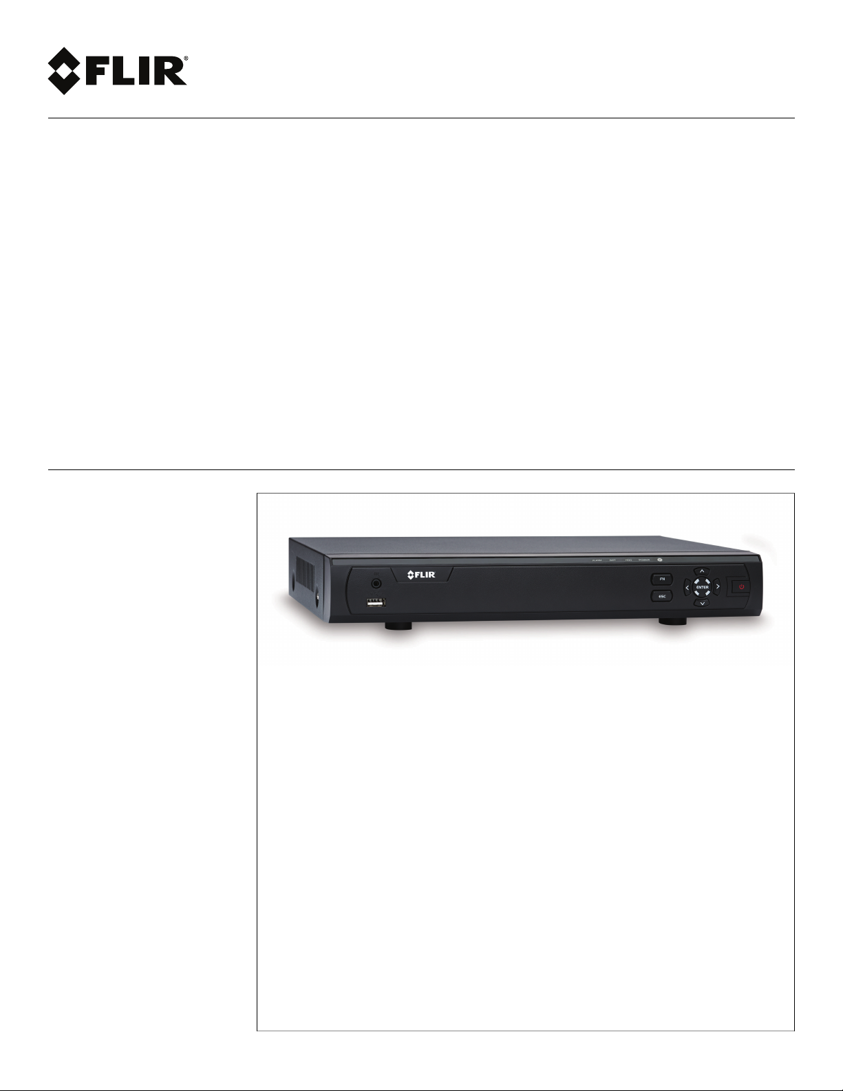
Instruction Manual
M3100E Series
Page 2

Page 3

Instruction Manual
M3100E Series
#LX400028; r.27370/27370; en-US
iii
Page 4
Thank you for purchasing this product. FLIR is committed to providing our customers with a high quality,
reliable security solution.
This manual refers to the following models:
M3104E (4-channel)
M3108E (8-channel)
M3116E (16-channel)
For the latest online manual, downloads and product updates, and to learn about our complete line of
accessory products, please visit our website at:
www.flirsecurity.com/pro
WARNING
RISK OF ELECTRIC SHOCK
DO NOT OPEN
WARNING: TO REDUCE THE RISK OF ELECTRIC SHOCK DO NOT REMOVE
COVER. NO USER SERVICABLE PARTS INSIDE.
REFER SERVICING TO QUALIFIED SERVICE PERSONNEL.
The lightning flash with arrowhead symbol, within an equilateral
triangle, is intended to alert the user to the presence of uninsulated
"dangerous voltage" within the product’s enclosure that may be of
sufficient magnitude to constitute a risk of electric shock.
The exclamation point within an equilateral triangle is intended to
alert the user to the presence of important operating and
maintenance (servicing) instructions in the literature accompanying
the appliance.
WARNING: TO PREVENT FIRE OR SHOCK HAZARD, DO NOT EXPOSE THIS UNIT
TO RAIN OR MOISTURE.
CAUTION: TO PREVENT ELECTRIC SHOCK, MATCH WIDE BLADE OF THE PLUG
TO THE WIDE SLOT AND FULLY INSERT.
#LX400028; r.27370/27370; en-US
iv
Page 5

Table of contents
1 Important Safeguards ....... ............................... ........... ........... .. ......... .. .1
1.1 General Precautions ......... ........... ........... ........... ........... ........... ....1
1.2 Installation....... ........... ........... ........... ........... ........... ........... ........1
1.3 Service .. ......... .. ........... ........... ........... ........... ........... ........... ......3
1.4 Use.... ........... ........... ........... ........... ........... ........... ........... ......... 3
2 M3100E Series Features ....... ........... ........... ........... ........... ........... ......... 4
3 Getting Started (M3100E Series) ......... ........... .. ......... ........... ........... ......5
4 Front Panel (M3100E Series) . .. ......... .. ......... .. ......... .. ........... ........... ....... 6
5 Rear Panel (M3100E Series)...... ........... ........... ........... ........... ........... ..... 7
6 Basic Setup (M3100E Series) ........... ........... ........... ........... ........... ......... 9
6.1 Step 1: Connect the BNC Cameras...... ........... ........... .. ......... .. ........ 9
6.2 Step 2: Connect the Mouse.. ........... .. ......... .. ......... .. ........... ........... 9
6.3 Step 3: Connect the Ethernet Cable ........... ........... ........... ........... ....9
6.4 Step 4: Connect the Monitor.. ........... ........... ........... ........... ........... . 9
6.5 Step 5: Connect the Power Adapter and Power on the DVR...... ......... . 10
6.6 Step 6: Upgrade Firmware to Latest Version (if Available) ..... ........... .. 10
6.7 Step 7: Verify Camera Image........ .. ........... ........... ........... ........... . 10
6.8 Step 8: Set the Time ...................................... ........... ........... ...... 11
6.9 Default System Password & Port Numbers .. ........... ........... ........... .. 11
6.9.1 FLIR Cloud™ . ......... .. ........... ........... ........... ........... ........ 11
6.10 Quick Access to System Information .... ........... ........... .. ......... .. ...... 11
7 About MPX... ........... ........... ........... ........... ........... ........... .. ......... .. ...... 13
7.1 What types of cabling and run lengths does MPX work with?...... .. ...... 13
8 Mouse Control ........ ........... ........... ........... ........... ........... .. ......... .. ...... 14
9 Remote Control . ........... ........... ............................... ........... ........... ..... 15
9.1 Setting the Remote Control Address ..... .. ......... .. ........... ........... ..... 16
10 Using the System ........ ........... ........... ........... .. ......... .. ......... .. ......... .. .. 17
10.1 On-Screen Display .................. ........... ........... ........... ........... ...... 17
10.2 Using the Quick Menu.. .. ......... .. ......... .. ......... .. ........... ........... ..... 17
10.3 Adjusting Color Settings ..... ........... ........... ........... ........... .. ......... . 18
10.4 Using the Navigation Bar ......... ........... ........... ........... ........... ....... 19
10.5 Using the Camera Toolbar ....... .. ......... .. ......... .. ........... ........... ..... 20
10.5.1 Using Instant Playback ..... ........... ........... ........... ........... ... 20
10.5.2 Using Digital Zoom in Live Display .......... ........... ........... ..... 21
10.5.3 Using Real-time Backup .. ........... ........... ........... ........... .... 21
10.6 Using the Virtual Keyboard........ ........... ........... ........... ........... ...... 21
11 Setting The Time .......... .. ......... ........... ........... ........... ........... ........... ... 23
12 Recording.. .. ......... .. ......... .. ......... .. ........... ........... ........... ........... ........ 24
12.1 Video Recording Types ............ ........... ........... ........... ........... ...... 24
12.2 Main Stream and Sub Stream.. ........... ........... ........... ........... ........ 24
12.3 Setting up Scheduled or Manual Recording ....... .. ........... ........... ..... 24
12.4 Configuring Hard Drive Overwrite ... ........... ........... ........... ........... .. 25
13 Search (Playback) ... ........... ........... ........... ........... ........... ........... ........ 26
13.1 Playing Back Video from the Hard Drive...... ........... ........... ........... .. 26
13.2 Playback Controls ....... ........... ........... ........................................ 27
13.3 Playing Back from a USB Drive ...... ........... ........... ........... ........... .. 27
14 Backup........... ........... ........... ........... ........... ........... ........... ........... ..... 29
14.1 Formatting the USB Thumb Drive ........ ........... ........... ........... ........ 29
#LX400028; r.27370/27370; en-US
v
Page 6

Table of contents
14.2 Backing up Video.......... ........... ........... ........... ........... ........... ..... 30
14.3 Using Video Clip Backup ..... ........... ........... ........... ........... ........... 30
14.4 Viewing Backup Files...... ........... ........... ........... .......................... 31
14.4.1 Viewing Backup Files on PC .... ........... ........... ........... ........ 31
14.4.2 Viewing Backup Files on Mac ........ ........... ........... ........... .. 34
15 Managing Passwords and User Accounts....... ........... ........... ........... ..... 37
15.1 Changing Passwords...... ........... ........... .. ......... .. ......... .. ......... .. .. 37
15.2 Adding Users . ........... ........... ........... ........... ........... .. ......... .. ...... 38
15.3 Modifying Users .......... .......................................... .. ......... .. ...... 38
15.4 Deleting Users ... ........... ........... ........... ........... ........... ........... .... 39
15.5 Account Groups ................... ........... ........... ........... .. ......... .. ...... 39
15.6 Adding Groups ... ........... ........... ........... ........... ........... ........... .... 39
15.7 Modifying Groups .......... ........... ........... .. ......... .. ......... .. ......... .. .. 40
15.8 Deleting Groups ..... ........... ........... ........... ................................. 40
16 Using the Main Menu ..... ........... ........... ........... ........... ........... ........... .. 41
16.1 Camera ......... ........... ........... ........... ........................................ 41
16.1.1 Recording... ........... ........... ........... ........... ........... ........... 41
16.1.2 Configuring Recording Quality ......... ........... ........... ........... 42
16.1.3 Configuring Audio Recording ....... ........... ........... ........... .... 42
16.1.4 Configuring Snapshot Recording Settings.. ........... ........... .... 43
16.1.5 Creating Custom Channel Names.......................... .. ......... . 44
16.1.6 Selecting Cable Type ... ........... ........... ........... ........... ....... 45
16.2 Info ......... .. ........... .......................................... ........... ........... .. 46
16.2.1 HDD Info ......... .......................................... .. ......... .. ...... 46
16.2.2 Record Info... ........... ........... ........... ........... ........... ......... 46
16.2.3 Version ... .. ......... .. ......... .. ........... ........... ........... ........... . 47
16.2.4 Alarm Status .... ........... ........... ........... ........... ........... ...... 47
16.2.5 Online Users ........................... ........... ........... ........... ..... 48
16.2.6 Load......... ........... ........... ........... ........... ........... .. ......... . 48
16.2.7 Test........... ........... ........... ........... ........... ........... ........... 49
16.2.8 BPS .......... ........... ........... .. ......... .. ......... .. ........... ......... 49
16.2.9 Log ..... ........... ........... ........... ........... ........... ........... ...... 49
16.3 Setting.... ........... ........... ........... .......................................... ..... 51
16.3.1 Network ..... ........... ........... .......................................... .. 51
16.3.2 Selecting DHCP or Static IP Address (TCP/IP) .......... .. ......... . 51
16.3.3 Configuring System Ports (Connection)......... ........... ........... 52
16.3.4 Configuring DDNS Settings . ........... ........... ........... ........... . 52
16.3.5 Configuring Email Alerts ... .. ........... ........... ........... ........... . 53
16.3.6 Event...... ........... ........... ........... ........... ......................... 55
16.3.7 Configuring Motion Detection......... ........... ........... ........... .. 55
16.3.8 Configuring Video Loss Settings ........... ........... ........... ....... 57
16.3.9 Configuring Hard Drive Warnings......... ........... ........... ........ 57
16.3.10 Configuring Network Warnings . ........... ........... ........... ........ 58
16.3.11 Storage.......... ........... ........... ........... ........... ........... ....... 59
16.3.12 Configuring the Video Recording Schedule ....... .. ......... .. ...... 59
16.3.13 Configuring Pre-Recording . ........... ........... ........... ........... .. 60
16.3.14 Configuring the Snapshot Schedule ..... ........... ........... ........ 61
16.3.15 Configuring Holidays........ .. ........... ........... ....................... 61
16.3.16 Formatting the Hard Drive . ........... ........... ........... ........... ... 62
16.3.17 Configuring Hard Drive Type........ ........... ........... ........... .... 63
#LX400028; r.27370/27370; en-US
vi
Page 7

Table of contents
16.3.18 Configuring General System Settings ......... ........... ........... .. 63
16.3.19 Setting the Monitor Resolution (Display) ........... .. ......... .. ...... 64
16.3.20 Saving Your System Configuration to a USB Flash
Drive ....... ................................. ......... .. ......... .. ......... .. .. 65
16.3.21 Setting the System to Factory Defaults...... ........... ........... .... 66
16.3.22 Upgrading Firmware from USB.. .. ......... .. ........... ........... ..... 67
16.4 Shutdown.... .. ......... .. ......... .. ........... ........... ........... ........... ........ 69
17 Connecting to Your System Over the Internet on PC or Mac ....... ........... .. 70
17.1 System Requirements..... ........... ........... ........... ........... ........... .... 70
17.2 Step 1 of 3: Connect your System to Your Router ...... ........... ............ 70
17.3 Step 2 of 3: Obtain the system’s Device ID..... .. ......... .. ........... ......... 71
17.4 Step 3 of 3: Connect to the System Over the Internet ....... ........... ...... 71
18 Using FLIR Cloud™ Client for PC or Mac .. ........... ........... ........... ........... 75
18.1 Home Page ..... .. ........... ........... ........... ........... ........... ........... .... 75
18.2 Live View ....... ........... ........... ........... ........... ............................. 75
18.2.1 Live View Controls............. ........... ........... ........... .. ......... . 76
18.2.2 Opening Live View in Multiple Monitors ....... ........... ........... .. 77
18.3 Controlling PTZ Cameras .... ........... .. ......... .. ......... .. ........... ......... 78
18.3.1 PTZ Presets... ........... ........... ........... ........... .. ......... .. ...... 79
18.3.2 PTZ Tours.... ........... ........... ........... ........... ........... .......... 80
18.3.3 PTZ Pattern ........... ........... ........... ........... ........... ........... 81
18.3.4 PTZ Scan ....... .. ......... .. ......... .. ......... .. ........... ........... ..... 82
18.3.5 PTZ Pan...... ........... ........... ................................. ......... . 82
18.4 Playback. ........... ........... ........... ........... ........... ........... ........... ... 82
18.5 Playback Controls ....... ........... ........... ........................................ 84
18.6 Downloading Video to your Computer Hard Drive... ........... ........... .... 85
18.7 Alarm .......... ........... ........... ........... ........... ........... ........... ......... 86
18.8 Log.... ........... ........... .. ......... .. ......... .. ......... .. ........... ........... ..... 87
18.9 E-map .......... ........... ........... ........... ........... ........... .. ......... .. ...... 88
18.10 Devices .. ........... .. ......... .. ......... .. ........... ........... ........... ............ 90
18.11 Device Config ......... ........... ........... ........... ........... ........... .......... 91
18.12 Alarm CFG .. .. ......... .. ......... .. ........... ........... ........... ........... ........ 91
18.13 Tour & Task ....... ........... ........... ........... ........... ........... ........... .... 94
18.14 Account ..... ........... ........... ........... .. ......... .. ......... .. ........... ......... 95
18.14.1 Managing User Accounts..... ........... ........... ........... ........... 95
18.14.2 Managing Roles........ ........... ........... ........... ........... ......... 97
18.15 General ....... ........... ........... ........... ........... ........... ........... ......... 98
18.15.1 Basic.. ........... .. ......... .. ......... .. ......... .. ........... ........... ..... 98
18.15.2 File ..... ........... ........... ........... ........... ........... ........... ...... 98
18.15.3 Alarm Prompt ........... ........... ........... ........... ........... ......... 99
18.15.4 Version .......... ........... ........... ........... ........... ........... ..... 100
19 Connecting to your System Using Smartphone or Tablet Apps. ........... .. 101
19.1 iPhone........... ........... ........... ........... ........... ........... ........... ..... 101
19.1.1 Prerequisites....... .. ......... .. ........... ........... ..................... 101
19.1.2 Connecting to your System on iPhone............ ........... ........ 101
19.1.3 Live View Interface ...... .. ......... .. ......... .. ........... ........... ... 102
19.1.4 Controlling PTZ Cameras......... ........... ........... ........... ..... 103
19.1.5 Viewing Snapshots and Videos with Local Files ........ .......... 104
19.1.6 Using Playback Mode on iPhone ..... ........... ........... .......... 105
19.1.7 Enabling Push Notifications ......... ........... ........... ........... .. 106
#LX400028; r.27370/27370; en-US
vii
Page 8

Table of contents
19.1.8 Using the Event List ..... ........... ........... ........... ........... ..... 108
19.1.9 Using Favorites.... .. ......... .. ........... ........... ........... .......... 109
19.1.10 Using the E-Map ........... ........... ........... ........... ........... ... 110
19.1.11 Device Manager......... ........... ........... ........... .. ......... .. .... 112
19.1.12 Adding Devices Using an IP or DDNS Address
(Advanced)...... ........... ........... ........... ........... ........... .... 113
19.2 iPad ........... ........... ........... ........... ........... ........... ........... ........ 115
19.2.1 Prerequisites....... .. ......... .. ........... ........... ..................... 115
19.2.2 Connecting to your system on an iPad ....... ........... ........... . 115
19.2.3 Live View Interface ...... .. ......... .. ......... .. ........... ........... ... 116
19.2.4 Controlling PTZ Cameras......... ........... ........... ........... ..... 117
19.2.5 Using Playback Mode on iPad. ......... .. ......... .. ........... ....... 118
19.2.6 Using Local File to View Manual Recordings ........ ........... ... 120
19.2.7 Enabling Push Notifications ......... ........... ........... ........... .. 121
19.2.8 Using the Event List ..... ........... ........... ........... ........... ..... 123
19.2.9 Using Favorites.... .. ......... .. ........... ........... ........... .......... 124
19.2.10 Using the E-Map ........... ........... ........... ........... ........... ... 125
19.2.11 Using the Device Manager .......... ........... ........... ........... .. 127
19.2.12 Adding Devices Using an IP or DDNS Address
(Advanced)...... ........... ........... ........... ........... ........... .... 127
19.3 Android ... ........... ........... ........... ........... ........... ........... ........... 130
19.3.1 Prerequisites....... .. ......... .. ........... ........... ..................... 130
19.3.2 Connecting to your System on Android ....... ........... ........... 130
19.3.3 Live View Interface ...... .. ......... .. ......... .. ........... ........... ... 131
19.3.4 Controlling PTZ Cameras......... ........... ........... ........... ..... 132
19.3.5 Viewing Snapshots and Videos with Local Files ........ .......... 133
19.3.6 Using Playback Mode on Android ..... ........... ........... ......... 133
19.3.7 Enabling Push Notifications ......... ........... ........... ........... .. 135
19.3.8 Using the Event List ..... ........... ........... ........... ........... ..... 136
19.3.9 Using Favorites.... .. ......... .. ........... ........... ........... .......... 136
19.3.10 Using the E-Map ........... ........... ........... ........... ........... ... 138
19.3.11 Device Manager......... ........... ........... ........... .. ......... .. .... 139
19.3.12 Adding Devices Using an IP or DDNS Address
(Advanced)...... ........... ........... ........... ........... ........... .... 140
20 DDNS Setup (Advanced) ............ ........... ........... ........... ........... .. ........ 142
20.1 Accessing your System within a Local Network (LAN)........ .. ......... .. 142
20.1.1 Step 1 of 3: Connect your System to Your Router ......... ....... 142
20.1.2 Step 2 of 3: Obtain the System’s Local IP Address ......... .. .... 143
20.1.3 Step 3 of 3: Connect to the System’s Local IP
Address .. .. ......... .. ......... .. ........... ........... ........... .......... 143
20.2 DDNS Setup—Access your System Remotely over the
Internet...... ........... ........... ........... .. ......... .. ......... .. ........... ....... 145
20.2.1 Step 1 of 4: Port Forwarding ........ .. ......... .. ......... .. ......... .. 146
20.2.2 Step 2 of 4: Create a DDNS Account ........... ........... .......... 146
20.2.3 Step 3 of 4: Enable DDNS on the System ......... ........... ...... 147
20.2.4 Step 4 of 4: Connect to the System’s DDNS Address ..... ...... 148
21 Connecting a PTZ Camera (M3100E Series) ..... .. ......... .. ......... .. ......... .. 152
21.1 Controlling a PTZ Camera (Local DVR).. .. ......... .. ........... ........... ... 152
21.2 Advanced PTZ Controls ....... ........... ........... ...................... ........ 153
21.2.1 Presets ....... .. ......... .. ........... ........... ........... ........... ...... 154
21.2.2 Tours........ ........... ......... .. ........... ........... ........... .......... 154
#LX400028; r.27370/27370; en-US
viii
Page 9

Table of contents
21.2.3 Pattern.. ........... ........... ........... ........... ........... ........... ... 155
21.2.4 Auto Scan ........................................ ........... ........... .... 155
22 M3100E Series Hard Drive Installation ... ........... ........... ........... ........... 157
22.1 Installing a Hard Drive..... .......................................... ........... .... 157
22.2 Removing the Hard Drive.......... ........... ........... ........... ........... .... 158
22.3 Formatting Hard Drives ......... ........... ........... ........... ........... ....... 159
23 Troubleshooting ............ ........... ........... ........... ........... ........... ......... .. 161
24 M3100E Series System Specifications . ........... ........... ........... ........... .. 163
25 Notices.... ........... ........... ........... ........... ........... ........... ........... .......... 166
25.1 FCC/IC Notice.......... ........... ........... ........... ........... ........... ....... 166
25.2 Modification.......... ........... ........... ........... ........... ........... .. ........ 166
25.3 ROHS ........... ........... .. ......... .. ......... .. ......... .. ........... ........... ... 166
#LX400028; r.27370/27370; en-US
ix
Page 10

Page 11
1
Important Safeguards
In addition to the careful attention devoted to quality standards in the manufacturing process of your product, safety is a major factor in the design of every instrument. However,
safety is your responsibility too. This sheet lists important information that will help to ensure your enjoyment and proper use of the product and accessory equipment. Please read
them carefully before operating and using your product.
1.1 General Precautions
1. All warnings and instructions in this manual should be followed.
2. Remove the plug from the outlet before cleaning. Do not use liquid aerosol detergents.
Use a water-dampened cloth for cleaning.
3. Do not use this product in humid or wet places.
4. Keep enough space around the product for ventilation. Slots and openings in the storage cabinet should not be blocked.
5. It is highly recommended to connect the product to a surge protector to protect from
damage caused by electrical surges. It is also recommended to connect the product to
an uninterruptible power supply (UPS), which has an internal battery that will keep the
product running in the event of a power outage.
CAUTION
Maintain electrical safety. Power line operated equipment or accessories connected to this product
should bear the UL listing mark or CSA certification mark on the accessory itself and should not be modified so as to defeat the safety features. This will help avoid any potential hazard from electrical shock or
fire. If in doubt, contact qualified service personnel.
1.2 Installation
1. Read and Follow Instructions - All the safety and operating instructions should be
read before the product is operated. Follow all operating instructions.
2. Retain Instructions - The safety and operating instructions should be retained for future reference.
3. Heed Warnings - Comply with all warnings on the product and in the operating
instructions.
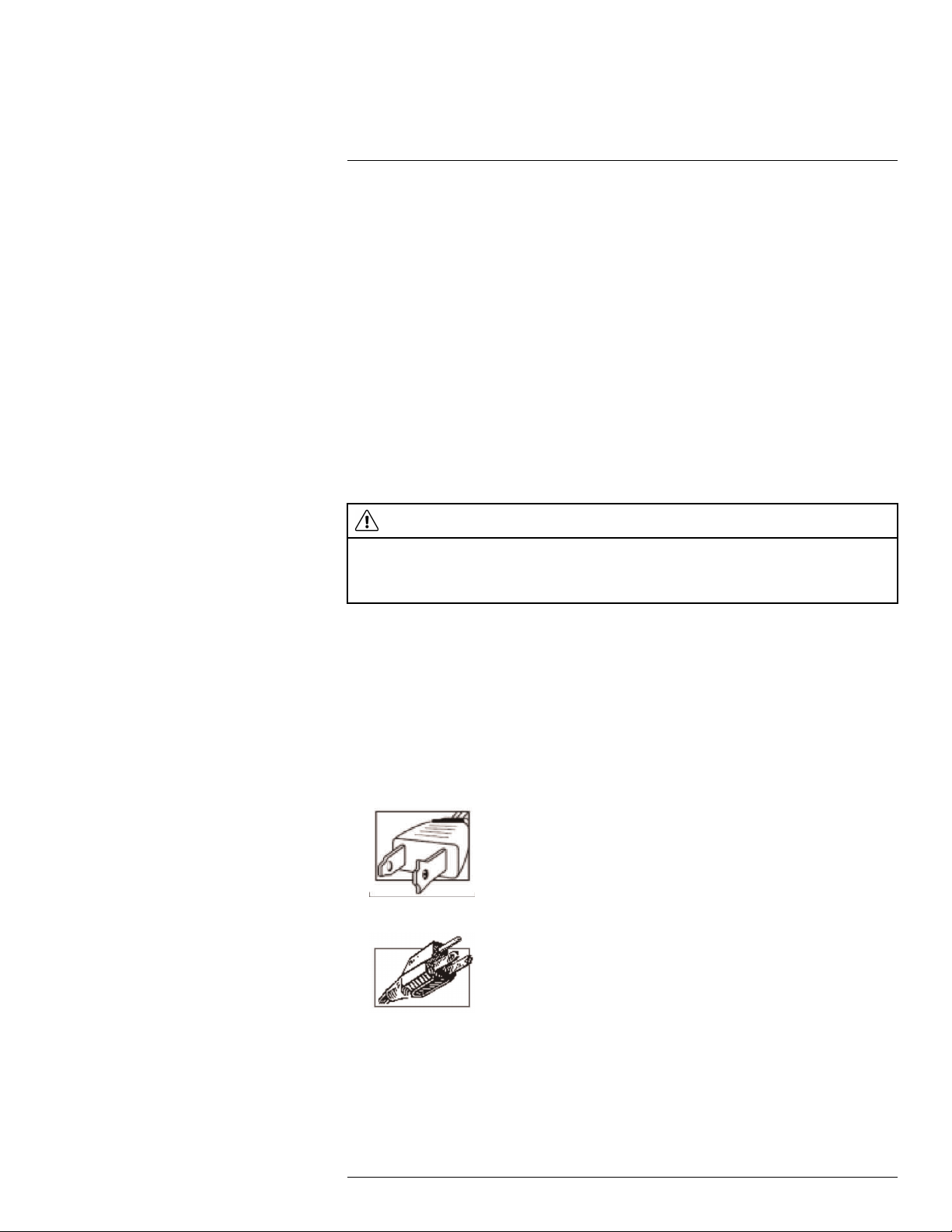
4. Polarization - Do not defeat the safety purpose of the polarized or grounding-type
plug.
A polarized plug has two blades with one wider than the other.
A grounding type plug has two blades and a third grounding prong.
The wide blade or the third prong are provided for your safety.
If the provided plug does not fit into your outlet, consult an electrician for replacement
of the obsolete outlet.
#LX400028; r.27370/27370; en-US
1
Page 12

1
Important Safeguards
5. Power Sources - This product should be operated only from the type of power source
indicated on the marking label. If you are not sure of the type of power supplied to your
location, consult your video dealer or local power company. For products intended to
operate from battery power, or other sources, refer to the operating instructions.
6. Overloading - Do not overload wall outlets or extension cords as this can result in the
risk of fire or electric shock. Overloaded AC outlets, extension cords, frayed power
cords, damaged or cracked wire insulation, and broken plugs are dangerous. They
may result in a shock or fire hazard. Periodically examine the cord, and if its appearance indicates damage or deteriorated insulation, have it replaced by your service
technician.
7. Power-Cord Protection - Power supply cords should be routed so that they are not
likely to be walked on or pinched by items placed upon or against them. Pay particular
attention to cords at plugs, convenience receptacles, and the point where they exit
from the product.
8. Surge Protectors - It is highly recommended that the product be connected to a
surge protector. Doing so will protect the product from damage caused by power
surges. Surge protectors should bear the UL listing mark or CSA certification mark.
9. Uninterruptible Power Supplies (UPS) - Because this product is designed for continuous, 24/7 operation, it is recommended that you connect the product to an uninterruptible power supply. An uninterruptible power supply has an internal battery that will
keep the product running in the event of a power outage. Uninterruptible power supplies should bear the UL listing mark or CSA certification mark.
10. Ventilation - Slots and openings in the case are provided for ventilation to ensure reli-
able operation of the product and to protect it from overheating. These openings must
not be blocked or covered. The openings should never be blocked by placing the product on a bed, sofa, rug, or other similar surface. This product should never be placed
near or over a radiator or heat register. This product should not be placed in a built-in
installation such as a bookcase or rack unless proper ventilation is provided and the
product manufacturer’s instructions have been followed.
11. Attachments - Do not use attachments unless recommended by the product manufacturer as they may cause a hazard.
12. Water and Moisture - Do not use this product near water — for example, near a bath
tub, wash bowl, kitchen sink or laundry tub, in a wet basement, near a swimming pool
and the like.
13. Heat - The product should be situated away from heat sources such as radiators, heat
registers, stoves, or other products (including amplifiers) that produce heat.
14. Accessories - Do not place this product on an unstable cart, stand, tripod, or table.
The product may fall, causing serious damage to the product. Use this product only
with a cart, stand, tripod, bracket, or table recommended by the manufacturer or sold
with the product. Any mounting of the product should follow the manufacturer’s instructions and use a mounting accessory recommended by the manufacturer.
15. Camera Extension Cables – Check the rating of your extension cable(s) to verify
compliance with your local authority regulations prior to installation.
16. Mounting - The cameras provided with this system should be mounted only as instructed in this guide or the instructions that came with your cameras, using the provided mounting brackets.
#LX400028; r.27370/27370; en-US
2
Page 13

1
Important Safeguards
17. Camera Installation - Cameras are not intended for submersion in water. Not all cameras can be installed outdoors. Check your camera environmental rating to confirm if
they can be installed outdoors. When installing cameras outdoors, installation in a
sheltered area is required.
1.3 Service
1. Servicing - Do not attempt to service this product yourself, as opening or removing
covers may expose you to dangerous voltage or other hazards. Refer all servicing to
qualified service personnel.
2. Conditions Requiring Service - Unplug this product from the wall outlet and refer
servicing to qualified service personnel under the following conditions:
• When the power supply cord or plug is damaged.
• If liquid has been spilled or objects have fallen into the product.
• If the product has been exposed to rain or water.
• If the product has been dropped or the cabinet has been damaged
• If the product does not operate normally by following the operating instructions. Ad-
just only those controls that are covered by the operating instructions. Improper adjustment of other controls may result in damage and will often require extensive
work by a qualified technician to restore the product to its normal operation.
• When the product exhibits a distinct change in performance. This indicates a need
for service.
3. Replacement Parts - When replacement parts are required, have the service technician verify that the replacements used have the same safety characteristics as the original parts. Use of replacements specified by the product manufacturer can prevent fire,
electric shock, or other hazards.
4. Safety Check - Upon completion of any service or repairs to this product, ask the
service technician to perform safety checks recommended by the manufacturer to determine that the product is in safe operating condition.
1.4 Use
1. Cleaning - Unplug the product from the wall outlet before cleaning. Do not use liquid
cleaners or aerosol cleaners. Use a damp cloth for cleaning.
2. Product and Cart Combination - When product is installed on a cart, product and
cart combination should be moved with care. Quick stops, excessive force, and uneven surfaces may cause the product and cart combination to overturn.
3. Object and Liquid Entry - Never push objects of any kind into this product through
openings as they may touch dangerous voltage points or “short-out” parts that could
result in a fire or electric shock. Never spill liquid of any kind on the product.
4. Lightning - For added protection of this product during a lightning storm, or when it is
left unattended and unused for long periods of time, unplug it from the wall outlet and
disconnect the antenna or cable system. This will prevent damage to the product due
to lightning and power line surges.
#LX400028; r.27370/27370; en-US
3
Page 14
2
M3100E Series Features
Features
• Supports MPX HD 1080p/720p cameras and standard analog cameras
• Ideal for retrofit using existing coax cable
• Easy, Secure Cloud connection
• Zero video latency
• Cabling up to 2300ft/700m
• Duplex transmission for camera control (PTZ, focus, alarm trigger)
• FLIR DDNS service option
• H.264 video compression
• HDMI/VGA simultaneous video output
• Audio In / Out
• Supports 1x HDD up to 4TB, 2x USB 2.0 ports
• RS-485 supports Pelco D & P PTZ
#LX400028; r.27370/27370; en-US
4
Page 15
3
Getting Started (M3100E Series)
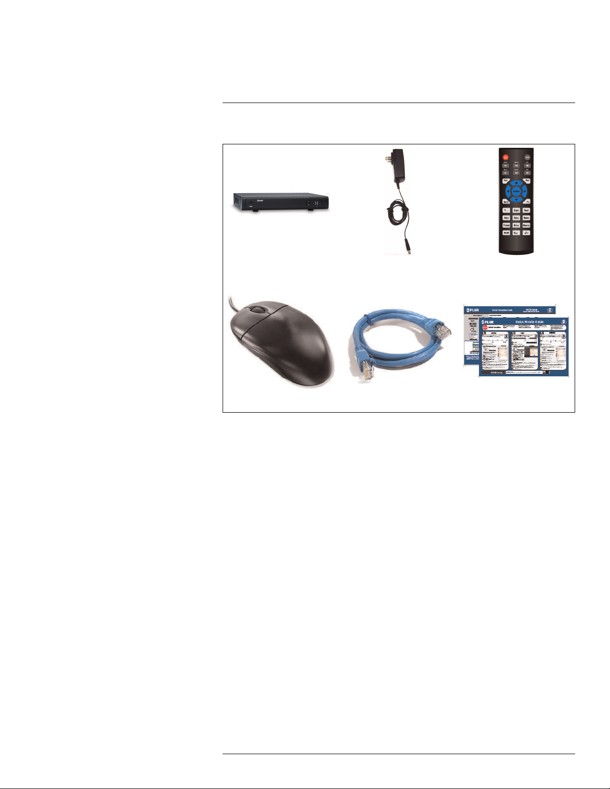
The system comes with the following components:
DVR (Digital Video Recorder) 12V DC power supply
USB mouse Ethernet cable Quick Start Guides
Hard drive size, number of channels, and camera configuration may vary by model. Please
refer to your package for specific details. Check your package to confirm that you have received the complete system, including all components shown above.
Remote control
(may not be exactly as shown)
#LX400028; r.27370/27370; en-US
5
Page 16

4
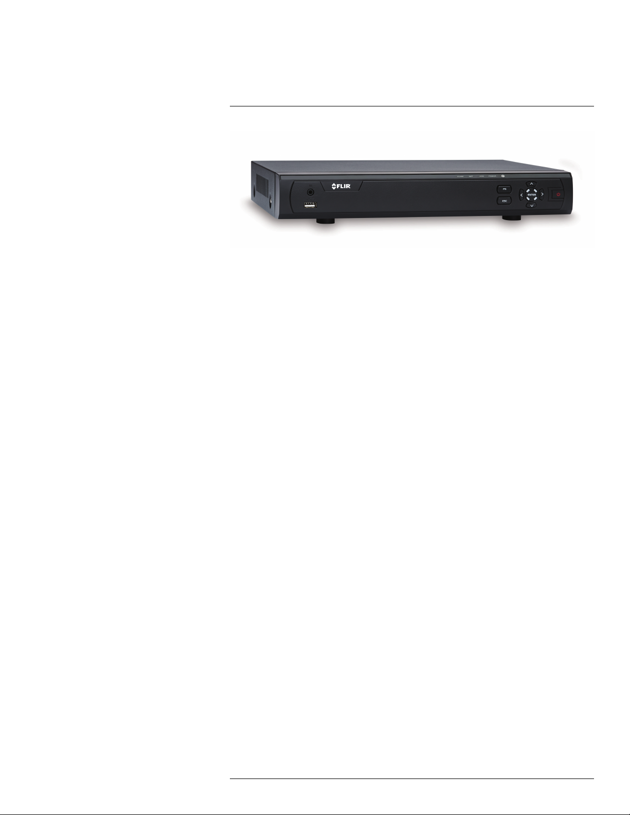
Front Panel (M3100E Series)
1. USB port: Connect a USB mouse (included) or connect a USB flash drive (not included) for data backup or firmware upgrades.
2. IR: Not supported.
3. IR receiver and LED indicators: IR receiver for the remote control. Keep the IR receiver clear from obstructions.
• ALARM: Not supported.
• NET: Glows when network is in normal state. Turns off when there is a network error.
• HDD: Glows to indicate hard drive is in normal state. Turns off when there is a hard
drive error.
• POWER: Glows to indicate the system is on.
4. FN: Performs special functions in some menus.
5. ESC: In menus, press to go back / exit menus. In playback, press to return to live view.
6. Directional buttons:
• ENTER: From live view, press once to open the System Information screen. In me-
nus, press to confirm menu options.
• Directional buttons: Press to move cursor in menus. In live view, press up to
change split screen layout; press left / right to select channels when single-channel
mode is selected.
7. Power button: Press and hold to power off the system (system password required).
Press to power the system back on.
#LX400028; r.27370/27370; en-US
6
Page 17

5
Rear Panel (M3100E Series)
4–Channel
8–Channel
1. On / Off switch: Turns the DVR on or off.
2. DC12V: Connect the included AC power adapter.
3. USB port(s): Connect a USB mouse (included) or USB flash drive (not included) for
data backup or firmware updates.
4. A/B: Connect RS485 cables.
NOTE
System is compatible with FLIR MPX PTZ cameras (not included) only. See 21 Connecting a PTZ
Camera (M3100E Series), page 152 for details.
5. HDMI: Connect to an HDMI monitor or TV (not included) to view the system interface.
6. LAN: Connect a CAT 5 RJ45 Ethernet cable for local and remote connectivity.
7. Audio IN/Audio OUT: RCA input and output for 1–channel audio recording.
8. Video input: Connect FLIR MPX cameras to the system.
9. VGA: Connect a VGA monitor (not included) to view the system interface.
16–Channel
1. DC12V: Connect the included AC power adapter.
#LX400028; r.27370/27370; en-US
7
Page 18

5
Rear Panel (M3100E Series)
2. A/B: Connect RS485 cables.
NOTE
System is compatible with FLIR MPX PTZ cameras (not included) only. See 21 Connecting a PTZ
Camera (M3100E Series), page 152 for details.
3. LAN: Connect a CAT 5 RJ45 Ethernet cable for local and remote connectivity.
4. USB port(s): Connect a USB mouse (included) or USB flash drive (not included) for
data backup or firmware updates.
5. VGA: Connect a VGA monitor (not included) to view the system interface.
6. HDMI: Connect to an HDMI monitor or TV (not included) to view the system interface.
7. Audio IN/Audio OUT: RCA input and output for 1–channel audio recording.
8. Video input: Connect FLIR MPX cameras.
9. On / Off switch: Turns the DVR on or off.
#LX400028; r.27370/27370; en-US
8
Page 19
6
Basic Setup (M3100E Series)
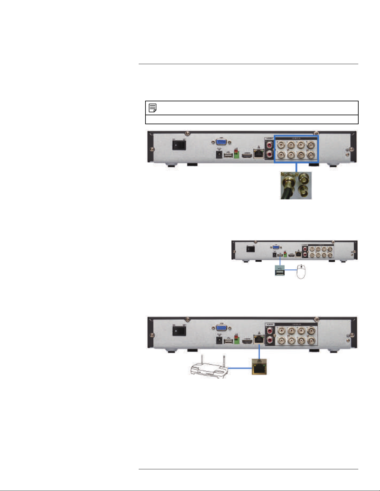
6.1 Step 1: Connect the BNC Cameras
• Connect FLIR MPX cameras to the Video Input ports on the rear panel of the DVR.
NOTE
The system is compatible with FLIR MPX cameras only.
Push and twist the BNC connector clockwise to secure it to the BNC port.
6.2 Step 2: Connect the Mouse
• Connect a USB mouse (included) to one of the USB ports.
6.3 Step 3: Connect the Ethernet Cable
• Connect an Ethernet cable (included) to the LAN port on the rear panel of the DVR.
Connect the other end of the Ethernet cable to a router on your network.
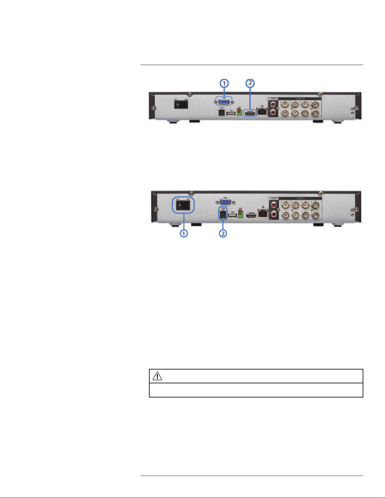
6.4 Step 4: Connect the Monitor
• Connect the included HDMI cable from the HDMI port to the TV or monitor
(recommended).
OR
• Connect a VGA cable (not included) from the VGA port to the monitor.
#LX400028; r.27370/27370; en-US
9
Page 20
6
Basic Setup (M3100E Series)
1. VGA Port
2. HDMI Port
6.5 Step 5: Connect the Power Adapter and Power on the DVR
1. Connect the included power adapter to the DC 12V port. Connect the end of the power
adapter to a wall socket or a surge protector.
2. Turn the power switch to ON to turn on the DVR.
1. On / Off Switch
2. DC 12V Port
At startup, the system performs a basic system check and runs an initial loading sequence.
After a few moments, the system loads a live display view.
6.6 Step 6: Upgrade Firmware to Latest Version (if Available)
If a firmware upgrade is available, you will be asked to install it once the system starts up.
It is required to upgrade your system firmware and client software or mobile apps to the latest version to enable remote connection to the system.
If a firmware upgrade is available:
1. After startup, a notification will appear asking you to upgrade the firmware. Click OK to
upgrade.
2. Enter the system user name (default: admin) and password (default: 000000) and
click OK. Wait for the firmware update to complete. The system will restart once the
firmware has been upgraded.
WARNING
DO NOT POWER OFF THE SYSTEM OR DISCONNECT THE POWER CABLE DURING FIRMWARE INSTALLATION.
6.7 Step 7: Verify Camera Image
• Power on the cameras, and then verify the camera video quality before mounting the
cameras to a permanent location.
• Mount the cameras under a sheltered location. Always verify the outdoor rating of your
camera before installing it in a permanent location.
#LX400028; r.27370/27370; en-US
10
Page 21

6
Basic Setup (M3100E Series)
6.8 Step 8: Set the Time
• Set the system time and date for accurate video time stamps. Videos with inaccurate
times may not be valid as surveillance evidence.
• For details on setting the system time, see 11 Setting The Time, page 23.
6.9 Default System Password & Port Numbers
CAUTION
By default, the system user name is admin and the password is 000000. It is essential that you create
your own password. For details, see 15 Managing Passwords and User Accounts, page 37.
A user name and password is required to log in to the system. After logging on using a
computer or mobile device the first time, you will be asked to create a custom password
for the system.
Local system and remote connectivity (LAN & Internet) user name and password:
• Username: admin
• Password: 000000
Default ports for DDNS remote access:
• Port 80 (HTTP port)
• Port 35000 (Client port)
6.9.1 FLIR Cloud™
This system features the exclusive FLIR Cloud™. This is a cloud service that allows you to
connect to your system over the Internet via a secure handshake with our servers. This
means you can easily connect to your system without requiring any network configuration.
For details on setting up your system to connect to the Internet using FLIR
Cloud™:
• See 17 Connecting to Your System Over the Internet on PC or Mac, page 70.
OR
• See 19 Connecting to your System Using Smartphone or Tablet Apps, page 101.
Connectivity using FLIR’s free DDNS service is also available, and requires the ports listed
above to be port forwarded on your router. See 20 DDNS Setup (Advanced), page 142 for
DDNS setup instructions.
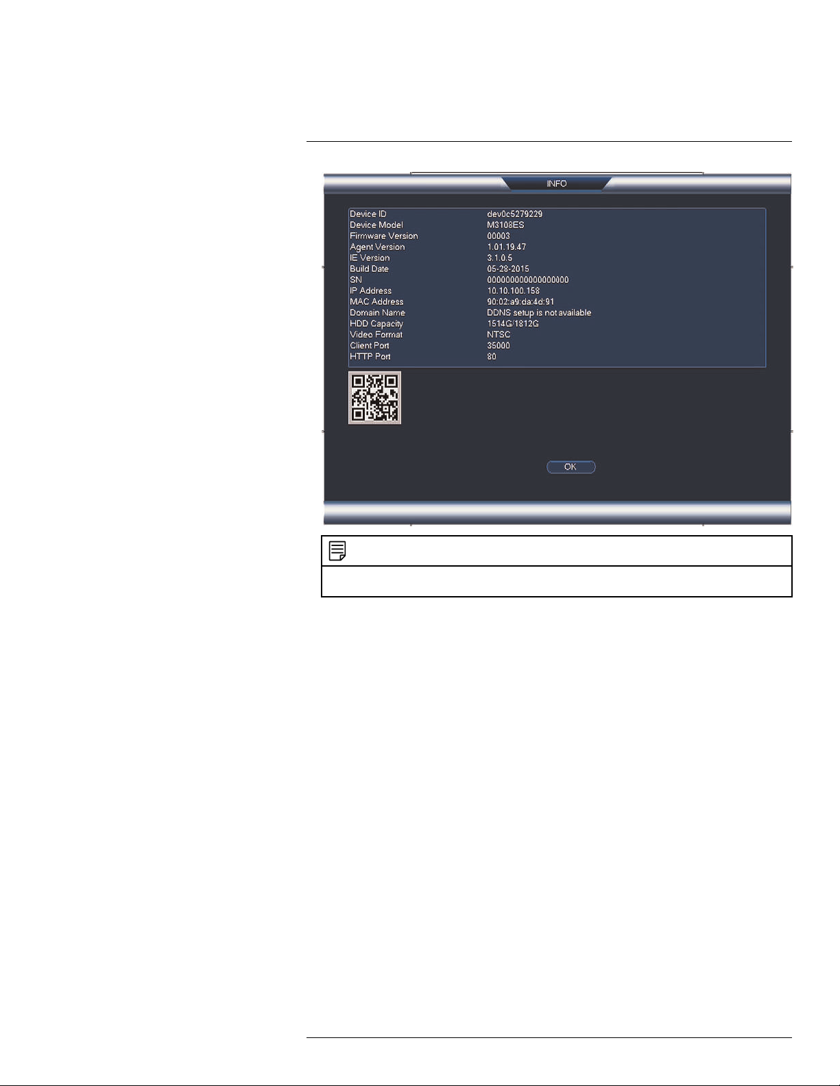
6.10 Quick Access to System Information
To quickly open a window that displays vital system information:
• Right-click to open the Quick Menu and click Info. Enter the system user name (default:
admin) and password (default: 000000).
OR
• Press the ENTER button on the front panel.
OR
• Press the ENTER button on the remote control.
#LX400028; r.27370/27370; en-US
11
Page 22
6
Basic Setup (M3100E Series)
NOTE
The QR code shown in the System Info screen can be scanned during mobile setup to enter the system’s Device ID.
#LX400028; r.27370/27370; en-US
12
Page 23
7
About MPX
FLIR MPX™ is a revolutionary video surveillance format powered by HD-CVI technology.
MPX delivers megapixel picture quality over coax, meaning you can upgrade your existing
analog systems to HD resolution (1MP & 2.1MP) over a single coax cable (RG59 & RG6
compatible).
NOTE
The DVRs covered in this manual are compatible with cameras.
7.1 What types of cabling and run lengths does MPX work with?
MPX allows a maximum cable run of up to 2300ft (700m) @ 720p or up to 2000ft (610m)
@ 1080p, depending on the type of cable used (see below). It is required that the cable
runs be made in a single run between camera and DVR, as daisychaining multiple cable
runs together can prevent the DVR from getting a picture from the camera or may impact
image quality. MPX supports standard UTP baluns for use with CAT5E or CAT6 cabling in
your installation. The baluns should have a 12V and BNC connection at both ends. You
can run up to 300ft (91m) per segment of CAT5E or CAT6.
Cable Type Maximum Run Length
RG59 20AWG Conductor 95% Braid CSA/UL or C
(UL) approved
RG6 20AWG Conductor 95% Braid CSA/UL or C
(UL) approved
Analog CCTV Balun 720p: Up to 300ft (91m)
720p: Up to 1500ft (455m)
1080p: Up to 1000ft (300m)
720p: Up to 2300ft (700m)
1080p: Up to 2000ft (600m)
1080p: Up to 300ft (91m)
1
1. Long cable runs over 1000ft may be affected by electromechanical interference (EMI), which can increase the
amount of noise in the picture in some installations.
#LX400028; r.27370/27370; en-US
13
Page 24

8
Mouse Control
The mouse is the primary control device for the system. To connect a USB mouse:
• Connect a USB mouse to the USB port on the front or rear panel.
1. Left-button:
• In live view, click to open the Navigation Bar. Right-click to close the navigation bar.
• In live view, while in a split-screen display mode, double-click an individual channel
to view it in full-screen. Double-click again to return to the split-screen display mode.
• While navigating menus, click to open a menu option.
2. Right-button:
• During live view, right-click anywhere on the screen to open the Quick Menu.
• Within system menus, right-click to exit menus.
3. Scroll wheel: In live view, use the scroll wheel to zoom in/out.
#LX400028; r.27370/27370; en-US
14
Page 25

9
Remote Control
1. Power: Press and hold to power off the system. Press to power on.
2. Playback controls:
•
Pause/Play: In live view, press to enter playback mode. Press to play/pause
playback.
•
Reverse: Press to reverse playback/pause playback.
•
•
•
•
3. Esc: In menus, press to go back / exit menus. In playback, press to return to live view.
4. Directional keys:
• Enter: Press once to open the System Information screen; press twice to open the
• Press
• Press
5. Mult: Press to switch between full-screen and split-screen layouts.
6. Number keys:
• 1~0: In live view, press to open channels in full-screen.
• In menus, press to input numbers or text input.
• Shift: Press to change input types.
7. Add: Configure remote control address. See below for details.
8. Rec: Press to open manual record menu.
9. Fn: Press to perform special functions in some menus.
Fast: Press to increase playback speed.
Next: Press to skip to next video.
Previous: Press to skip to previous video.
Slow: Press for slow playback.
Navigation Bar. Press to confirm menu selections.
to move the menu cursor.
to change menu options.
#LX400028; r.27370/27370; en-US
15
Page 26
9
Remote Control
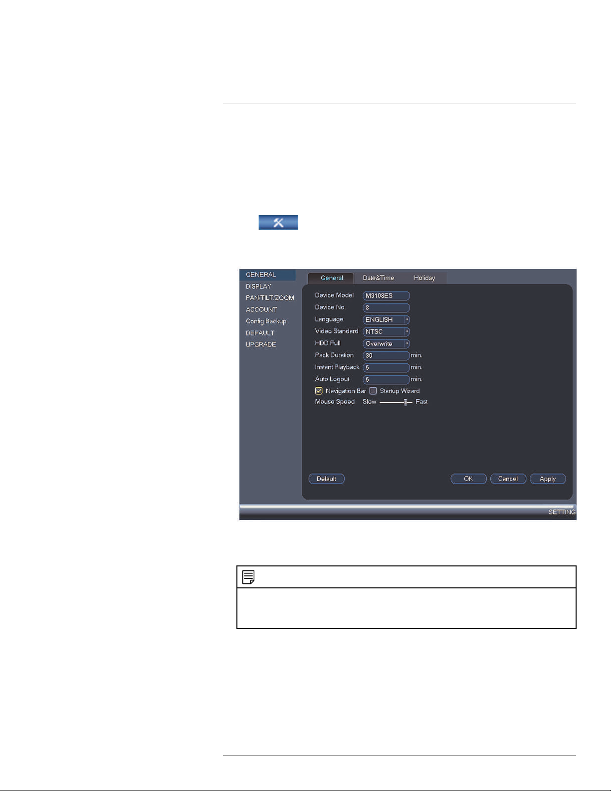
9.1 Setting the Remote Control Address
If you have more than one system, you can set up your remote control to pair with a specific system.
To set the remote control address:
1. Right-click and click Main Menu. Enter the system user name (default: admin) and
password (default: 000000).
2. Click
and then click Setting>General>General.
3. Under Device No., enter the address number you would like to assign to the remote
control.
4. Click OK.
5. Using the remote control, press Add. Then enter the address number and press Enter.
NOTE
When entering the address number using the remote, make sure that you press three digits. A single-digit number should be preceded by two zeros. A two-digit number should be preceded by one
zero. For example, if you entered 8 as the Device No., you have to press Add then 008 on the
remote.
#LX400028; r.27370/27370; en-US
16
Page 27
10
Using the System
Use the system’s graphical on-screen display to navigate menus and configure options
and settings.
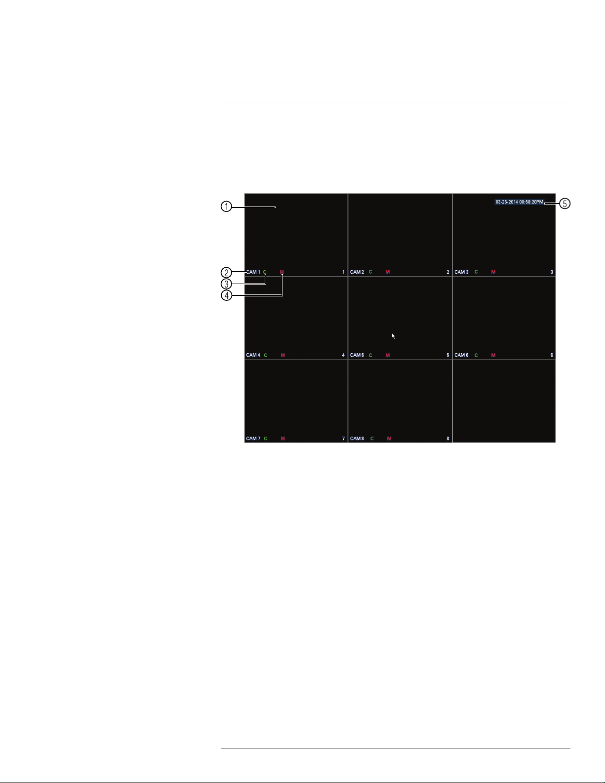
10.1 On-Screen Display
The system shows the following for all display views:
1. Display area:
• Double-click on a channel to view in full-screen; double-click again to return to split
screen.
• Right-click to open the Quick Menu.
• Left-click to open the Navigation Bar.
• Move the mouse to the top of a channel to view the Camera Toolbar.
• Click-and-drag cameras to rearrange the channel display. This does not affect the
channels each camera is connected or recording to.
2. Channel name
3. C: Camera is continuously recording.
4. M: Motion has been detected.
5. Date & time: Current system date and time. For details on setting the date and time,
see 11 Setting The Time, page 23.
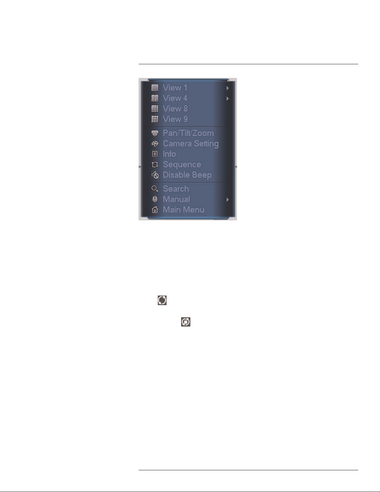
10.2 Using the Quick Menu
The Quick menu gives you access to the system’s key functions. To access the Quick
Menu, right-click the screen during live view.
#LX400028; r.27370/27370; en-US
17
Page 28
10
Using the System
The Quick Menu has the following options:
• View: Select a camera in full-screen or select a multi-channel display.
• Pan/Tilt/Zoom: Access controls for PTZ cameras (not included).
• Camera Setting: Configure color settings for cameras.
• Info: Opens the system information window.
• Sequence: Click to start/stop sequence mode.
• In sequence mode, the system will automatically cycle through connected cameras
every few seconds.
• A
will appear to show that sequence mode is on.
• Click the icon to pause sequence mode on the channel that is currently shown (icon
changes to
). Click again to resume sequence mode.
• Right-click and select Sequence to return to normal viewing mode.
• Disable Beep: Click to disable beep.
• Search: Search/playback recorded video. See 13 Search (Playback), page 26.
• Manual: Open the Record menu to select manual recording options. See 12.3 Setting
up Scheduled or Manual Recording, page 24.
• Main Menu: Open the Main Menu. See 16 Using the Main Menu, page 41.
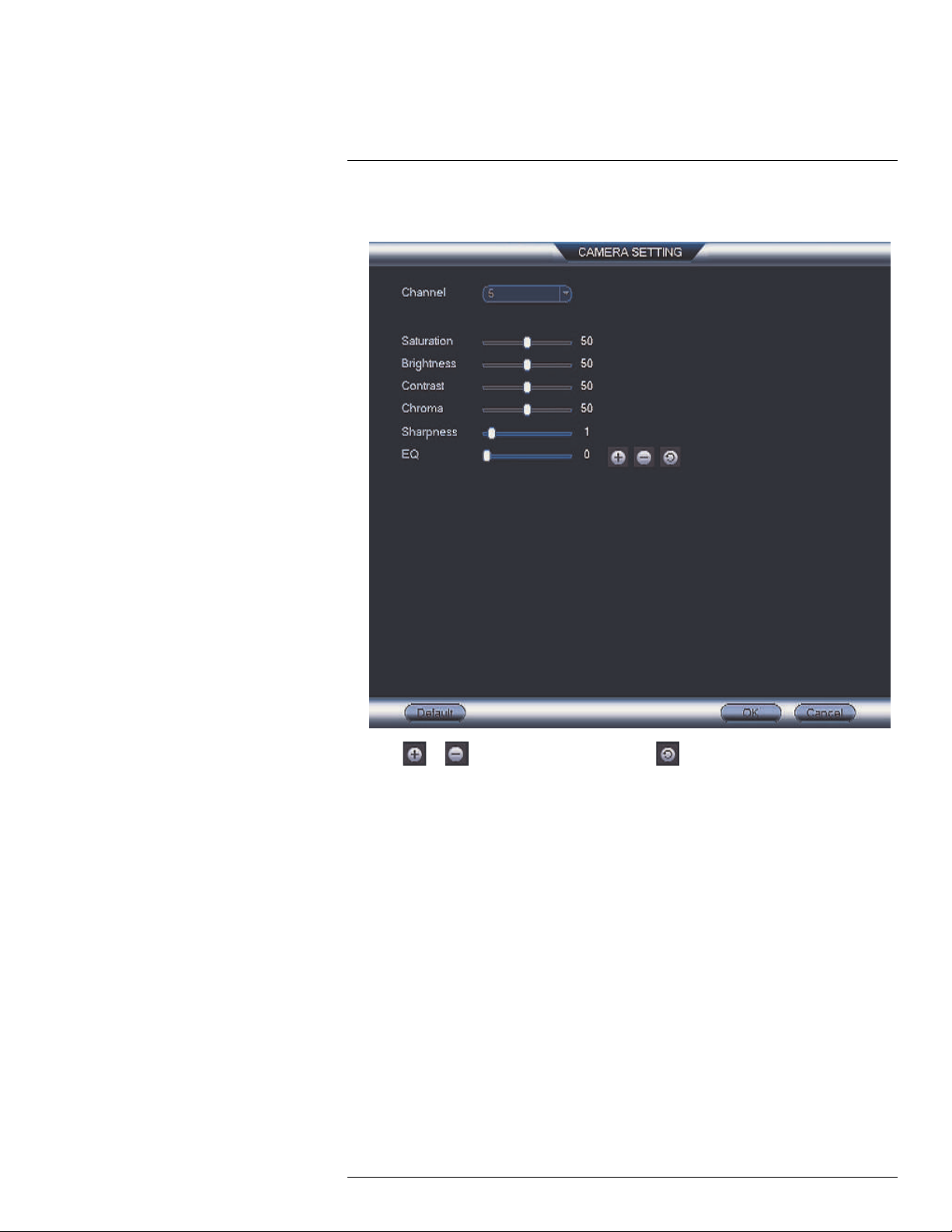
10.3 Adjusting Color Settings
Use the Camera Settings menu to adjust color settings for your cameras.
To adjust color settings:
1. Right-click on the channel you would like to configure and select Camera Setting. En-
ter the system password if prompted.
#LX400028; r.27370/27370; en-US
18
Page 29
10
Using the System
2. Adjust the Saturation, Brightness, Contrast, Chroma, and Sharpness settings that
the camera will use.
3. Click or to adjust the EQ setting. Click to reset the EQ setting to its default
value.
4. Click OK to save changes.
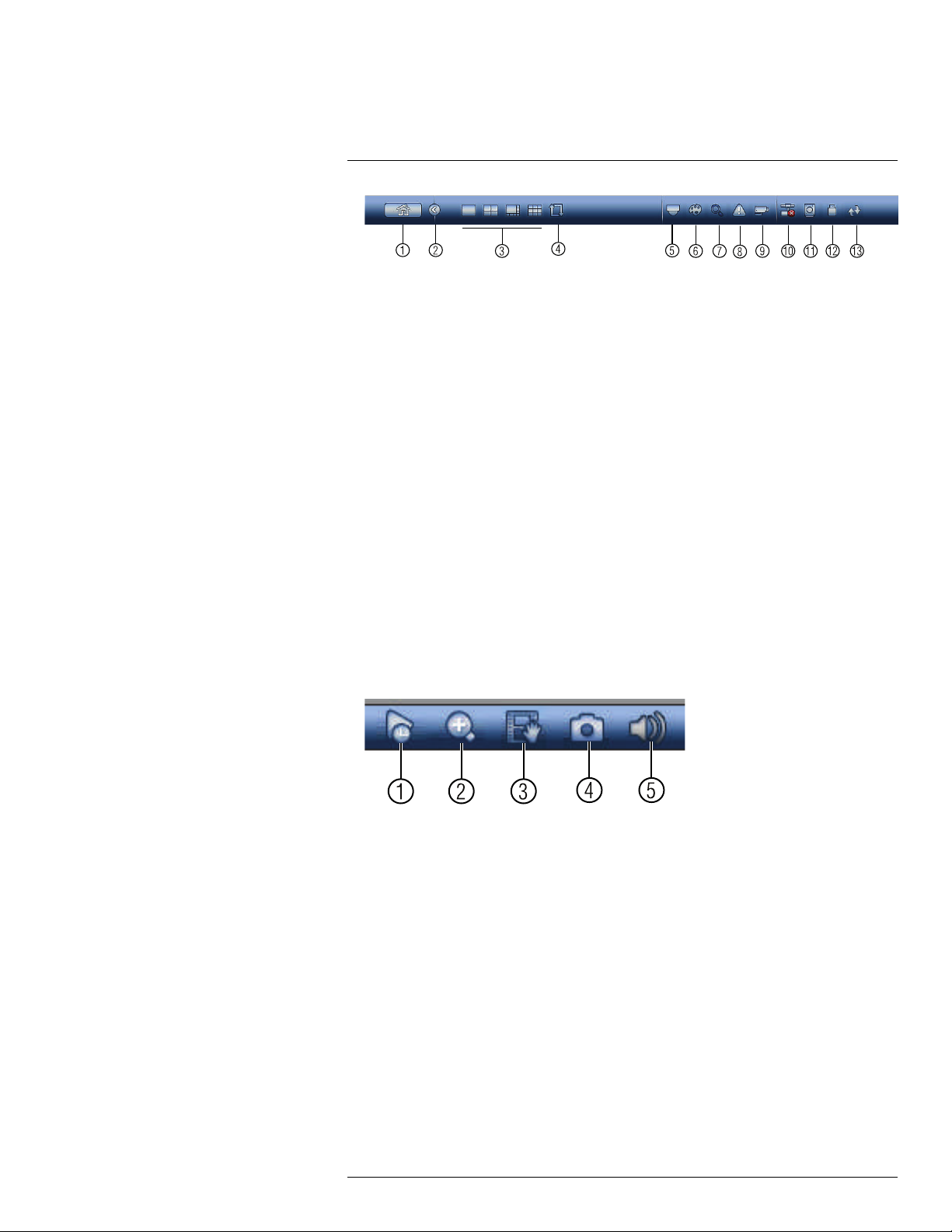
10.4 Using the Navigation Bar
The Navigation Bar gives quick access to certain functions and menus.
To open the Navigation bar:
• Left click on the screen to open the Navigation Bar. The Navigation Bar has the following options:
#LX400028; r.27370/27370; en-US
19
Page 30
10
Using the System
1. Main Menu
2. Collapse
3. Select display layout
4. Sequence: Click to start/stop sequence mode.
5. PTZ: Click to open PTZ controls.
6. Camera Setting: Click to open camera image settings.
7. Search: Search and playback recorded video. See 18.4 Playback, page 82.
8. Alarm Status: View alarms in progress. See 16.2.4 Alarm Status, page 47.
9. Channel Info: Click to access status information about connected cameras.
10. Network: Configure network settings for your system. See 16.3.1 Network, page 51.
11. HDD Manager: Manage hard drives connected to the system. See 16.3.16 Format-
ting the Hard Drive, page 62.
12. USB Manager: Click to access options for connected USB thumb drives (not in-
cluded). You can backup video, logs, or system configurations and install firmware
upgrades.
13. Upgrade: Click to check for firmware upgrades. Your system must be connected to
the Internet to check for firmware upgrades.
10.5 Using the Camera Toolbar
The Camera Toolbar is used to perform actions on a specific channel.
To access the Camera Toolbar:
• Move the mouse to the top of the channel display. The Camera Toolbar has the following options:
1. Instant Playback
2. Digital Zoom
3. Real-time backup
4. Snapshot
5. Mute / Unmute audio
10.5.1 Using Instant Playback
Instant Playback is used to playback the last 5~60 minutes of video from the selected
channel. You can also access Instant Playback in split-screen mode, while still viewing live
video from the other channels.
#LX400028; r.27370/27370; en-US
20
Page 31

10
Using the System
To use Instant Playback:
1. Move your mouse to the top of the channel display and click
NOTE
By default, the system will begin playback from 5 minutes ago. You can increase this to up to 60 mi-
nutes using the Instant Playback setting in Main Menu >
General.
.
> Setting > General >
2. Right-click to exit Instant Playback.
10.5.2 Using Digital Zoom in Live Display
1. Move your mouse to the top of the channel display and click
to activate digital
zoom. A check mark will appear in the icon to indicate digital zoom is activated.
NOTE
You may activate digital zoom in multiple channels at the same time.
2. Click and drag inside the channel to zoom in.
• Click and drag to pan the zoom area.
• Right-click to zoom out and select a new zoom area.
• Click
to disable digital zoom. Note that the channel will remain at the same
zoom level until you right-click inside it.
10.5.3 Using Real-time Backup
Real-time backup allows you to save footage from the live display to a USB thumb drive
(not included) or external hard drive (not included).
To use Real-time Backup:
1. Insert the USB thumb drive or external hard drive into one of the USB ports on the
system.
2. Move your mouse to the top of the channel display and click
to start Real-time
Backup.
3. Click
If the system prompts you to log in, you will need to click
logging in.
again to end Real-time Backup. The file is saved to your USB device.
NOTE
again to start Real-time Backup after
10.6 Using the Virtual Keyboard
The Virtual Keyboard is used to input text or numeric values in certain menus.
#LX400028; r.27370/27370; en-US
21
Page 32

10
Using the System
1. Backspace.
2. Enter capital letters.
3. Confirm entry.
#LX400028; r.27370/27370; en-US
22
Page 33

11
Setting The Time
CAUTION
It is highly recommended to set the date and time when first setting up your system.
Inaccurate time stamps may render your footage unusable for court evidence.
To set the date and time:
1. In the main viewing mode, right-click and click Main Menu.
2. Log in using the system user name (default: admin) and password (default: 000000).
3. Click
4. Under System Time, enter the current time and select your time zone. Then, click OK.
5. Check DST to enable auto Daylight Savings Time updates.
• You can adjust the Start Time and End Time for Daylights Savings Time if the default settings do
not match your region.
• Under DST Type, select Day of Week to set the start and end time based on a day and week (e.g.
2nd Sunday in March), or select Date to set the start and end time to a specific date.
6. (Optional) Check NTP to sync your system with an Internet time server. Click Manual
Update to instantly update the time.
and select Setting. Click General and select the Date&Time tab.
NOTE
NOTE
• Your system must have a constant connection to the Internet to use NTP.
• (Advanced) You can enter a custom NTP server under Server IP and Port, and you can select
how often the system will sync the time using Interval.
7. Click Apply to save changes.
#LX400028; r.27370/27370; en-US
23
Page 34
12
Recording
By default, the system is set to immediately record video from connected cameras continuously, 24 hours a day. You can customize the recording settings according to your needs.
12.1 Video Recording Types
The system supports the following recording types.
• Recording—Continuous: Normal, continuous recording. A
recording is in progress.
• Recording—Motion: The system records when motion is detected by the camera. An
icon is shown when motion is detected.
12.2 Main Stream and Sub Stream
The system employs two video recording streams, a Main Stream and a Sub Stream. Both
Main Stream and Sub Stream recording are enabled by default.
The Main Stream records high quality video to your system’s hard drive.
The Sub Stream records lower resolution video for efficient streaming to devices over the
Internet. Sub Stream recording must be enabled to view video recordings on a computer
or mobile device.
You can configure the video quality parameters for the Main Stream or Sub Stream. For
details, see 16.1.2 Configuring Recording Quality, page 42.
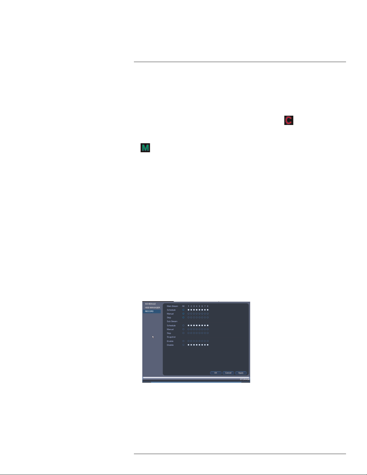
12.3 Setting up Scheduled or Manual Recording
You can set the system to record based on a schedule or you can manually turn recording
on and off. By default, the system is set to record on an always on recording schedule.
To configure the recording schedule, see 16.3.12 Configuring the Video Recording Sched-
ule, page 59.
To select between scheduled and manual recording:
1. Right-click and then select Manual>Record.
icon is shown when
#LX400028; r.27370/27370; en-US
24
Page 35

Recording12
2. Under Main Stream, select how the system will record the Main Stream for each
channel.
• Schedule: Main Stream Recording will follow the recording schedule.
• Manual: The system will record the Main Stream continuously as long as this option
is checked.
• Stop: The system will not record the Main Stream for this channel. This option is
not recommended.
3. Under Sub Stream, select how the system will record the Sub Stream for each
channel.
• Schedule: Sub Stream Recording will follow the recording schedule.
• Manual: The system will record the Sub Stream continuously as long as this option
is checked.
• Stop: The system will not record the Sub Stream for this channel.
4. Under Snapshot, select Enable to enable snapshot recording on each channel. Or,
select Disable to disable snapshot recording.
5. Click OK to save changes.
12.4 Configuring Hard Drive Overwrite
When the hard drive is full, the system will overwrite the oldest recordings by default. This
is recommended, as it makes sure that your system will continue to record without any input from you. You can also set the system to stop recording once the hard drive is full.
To configure hard drive overwrite:
1. Right-click and select Main Menu. Click
> Setting>General>General.
2. Under HDD Full, select Overwrite for the system to overwrite the oldest recordings
when the hard drive is full. Or, select Stop Record for the system to stop recording
when the hard drive is full.
3. Click OK to save changes.
#LX400028; r.27370/27370; en-US
25
Page 36

13
Search (Playback)
Search mode is used to navigate and playback recorded video files on the system.
13.1 Playing Back Video from the Hard Drive
1. From live view, right-click and then click Search.
2. Log in using the system user name (default: admin) and password (default: 000000).
3. Configure the following:
3.1. Use the calendar on the right to select the day to playback.
3.2. Use the drop-down menus to select the channels you would like to playback.
NOTE
Click the display options (
3.3. Click inside the video bar to select the playback time. The system will begin
playing back at the selected time.
) to playback multiple channels simultaneously.
#LX400028; r.27370/27370; en-US
26
Page 37

13
Search (Playback)
13.2 Playback Controls
1. Select playback device.
2. Calendar: Select the day to playback.
3. Channel select: Select channels to playback.
4. Video clip backup: Select video clip start and end times.
5. Backup video clip: Click to save selected clip.
6. Playback Bar: Click inside the bar to select a playback time.
7. Zoom Playback Bar: Select scope of time bar.
8. Recording types: Click to show/hide recording types.
9. Speed up
10. Slow
11. Previous/next frame
12. Play backward
13. Stop
14. Play
13.3 Playing Back from a USB Drive
If you have video files saved to a USB thumb drive (not included) or external hard drive
(not included), you can play them back using the system.
To play back from a USB drive:
1. Connect the USB thumb drive (not included) or USB external hard drive (not included)
with video files on it into a USB port on the system.
2. From live view, right-click and click Search.
3. Log in using the system user name (default: admin) and password (default: 000000).
#LX400028; r.27370/27370; en-US
27
Page 38

13
Search (Playback)
4. Select REC and select From IO Device. Click Browse to open the USB drive and
manually select the video file.
5. Select the video file you would like to open and click OK.
#LX400028; r.27370/27370; en-US
28
Page 39
14
Backup
Backup video files to external USB flash drive (not included) or self-powered USB external
hard drive (not included).
NOTE
USB external hard drives must be formatted in the FAT32 file format to be used with the system.
14.1 Formatting the USB Thumb Drive
It is recommended to format your USB thumb drive (not included) before using it with the
system.
CAUTION
Formatting the USB device will permanently erase all data.
To format a USB device:
1. Insert a USB thumb drive (not included) into one of the USB ports.
2. From live view, right-click and then select Main Menu. Login if prompted.
3. Click
4. Select the USB device you would like to format under Device Name and click Browse.
5. Click Format. Click OK to confirm.
>Backup.
#LX400028; r.27370/27370; en-US
29
Page 40

Backup14
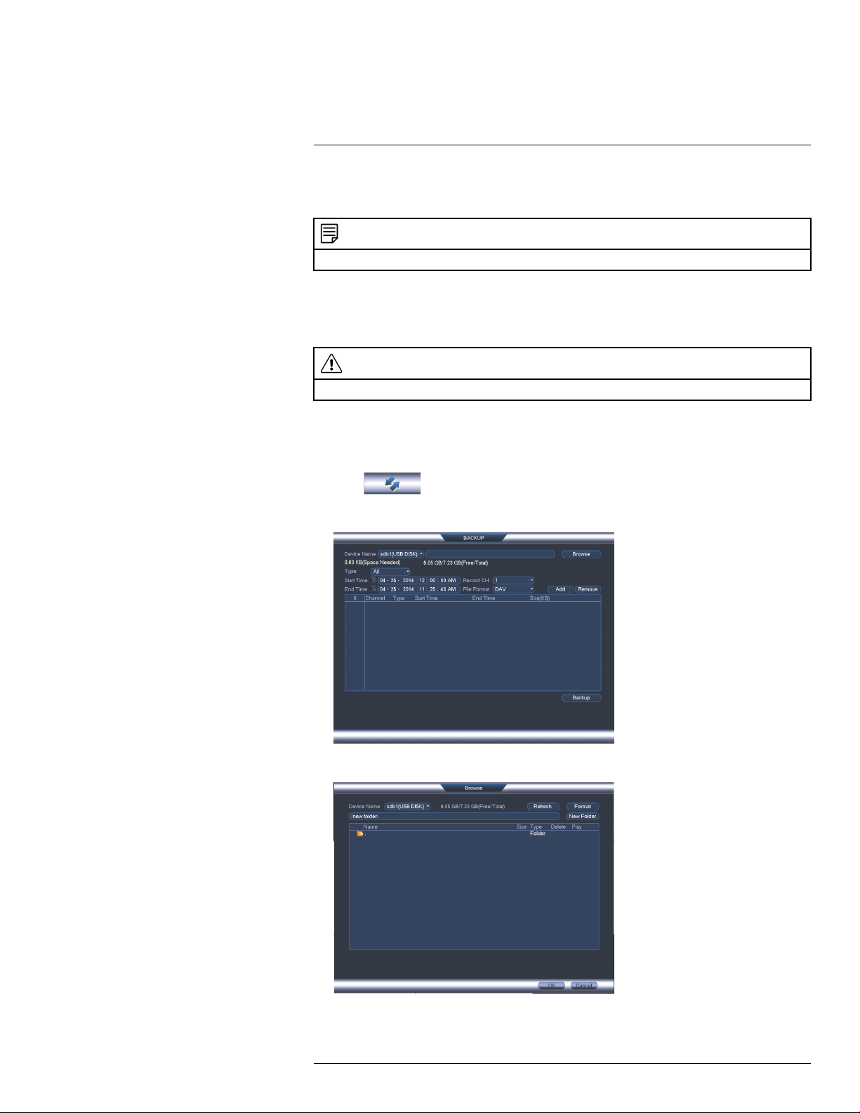
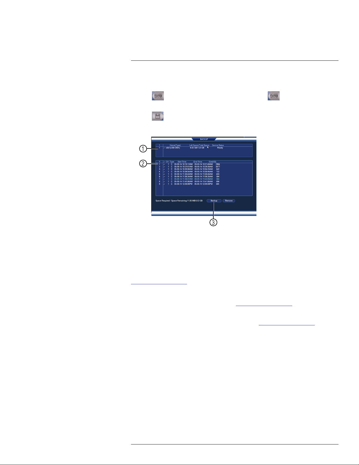
14.2 Backing up Video
1. Insert a USB thumb drive (not included) into one of the USB ports.
2. From live view, right-click and then select Main Menu. Login if prompted.
3. Click
>Backup.
4. Configure your search options:
• Select the USB device you would like to format under Device Name.
• Type: Select the recording type you would like to search for or select All to search
all recording types.
• Channel: Select the channel you would like to search or select All to search all
channels.
• File Format: Select DAV to save files to save files to .dav format. You can playback .
dav files using the FLIR video player software from www.flirsecurity.com/pro. Or, se-
lect ASF for .asf format. You can playback .asf files in VLC Media Player (free download from www.videolan.org) on PC or Mac.
NOTE
VLC Media Player is a free software available from www.videolan.org. VLC Media Player is not
supported by FLIR.
• Start Time/End Time: Select the start and end time for your search.
5. Click Add. A list of files that match your search criteria appears.
6. Check files you would like to backup and then click Backup. Wait for the backup to
complete.
NOTE
HD video files saved on the system may take up a large amount of disk space. The size of video files
selected and the amount of free space on your USB device is shown at the top of the screen.
14.3 Using Video Clip Backup
Video clip backup allows you to select a duration of video during playback mode and save
it to a USB device (not included).
To use Video Clip Backup:
1. Insert a USB flash drive (not included) or USB external hard drive (not included) into
one of the USB ports.
#LX400028; r.27370/27370; en-US
30
Page 41
Backup14
2. Start playing back video using the steps in 13.1 Playing Back Video from the Hard
Drive, page 26.
3. Click
to mark the beginning of the video clip. Click to mark the end of the
video clip.
4. Click
to open the Backup menu.
5. Configure the following:
5.1. Check the USB device where you would like to save the file.
5.2. Check the files you would like to backup.
5.3. Click Backup . Then click Start. Wait for the backup to complete before remov-
ing the USB flash drive.
14.4 Viewing Backup Files
To playback .dav backup video files, a Player is available for PC and Mac at
www.flirsecurity.com/pro.
14.4.1 Viewing Backup Files on PC
You can download Video Player for PC from www.flirsecurity.com/pro.
To view backup video files using the Player on PC:
1. Download and install the Video Player for PC from www.flirsecurity.com/pro.
#LX400028; r.27370/27370; en-US
31
Page 42

Backup14
2. Click
to open a back up video file.
3. Use the Player controls to control playback or select other files for playback.
Video Player Controls
1. File List: Double-click to open a file.
#LX400028; r.27370/27370; en-US
32
Page 43

Backup14
2. Display Area: Select the split-screen mode. Double-click a video file to expand. Click
the controls inside the display area to do the following:
•
: View information about the video file.
•
: Start/stop a manual recording from the video file.
•
: Take a snapshot from the video file.
•
: Close the video file.
3. Hide/show file list.
4. Playback controls:
•
: Playback files in sequence.
•
: Synchronize playback times.
: Play/pause playback.
•
•
: Stop playback.
•
: Previous frame.
: Next frame.
•
•
•
: Volume control.
: Playback speed.
5. Zoom Timeline.
6. Add Files: Click to open back up video files.
7. Digital Zoom: Click to activate digital zoom mode. Click and drag in the video to zoom
in. Right-click to unzoom.
8. Drag: When digital zoom is activated, click to activate drag mode. Then click and drag
in the video to view different areas of the image.
9. Full-screen: Click to open the player in full screen. Press ESC to exit full screen.
#LX400028; r.27370/27370; en-US
33
Page 44

Backup14
10. Config: Click to open the configuration menu for the player. From here you can control
the default file formats and save locations for snapshots and video files saved from the
player.
14.4.2 Viewing Backup Files on Mac
A Video Player for Mac is available from www.flirsecurity.com/pro.
To view backup video files using the Player on Mac:
1. Download Video Player for Mac from www.flirsecurity.com/pro.
2. Double click the downloaded file in Safari to extract the Smart Player app file.
3. Drag the Smart Player app to your Desktop or Applications list. Double click Smart
Player (
) to open it.
#LX400028; r.27370/27370; en-US
34
Page 45

Backup14
4. Click
to open a back up video file in another location.
5. Use the Player controls to control playback or select other files for playback.
Video Player Controls
1. File List: Double-click to open a file.
2. Display Area: Select the split-screen mode. Double-click a video file to expand. Click
the controls inside the display area to do the following:
•
: View information about the video file.
•
: Take a snapshot from the video file.
•
: Close the video file.
#LX400028; r.27370/27370; en-US
35
Page 46

Backup14
3. Hide/show file list.
4. Playback controls:
•
: When a video file ends, this button lets you select if you want the video player
to repeat the same file or play the next file.
•
: Play/pause playback.
•
: Stop playback.
•
: Previous file.
: Next file.
•
•
•
: Volume control.
: Playback speed.
5. Zoom Timeline.
6. Add Files: Click to open back up video files.
7. Full-screen: Click to open the player in full screen. Press ESC to exit full screen.
8. Config: Click to open the configuration menu for the player. From here you can control
the default file formats and save locations for snapshots and control the aspect ratio.
9. About: Click to see version information for the Player software.
#LX400028; r.27370/27370; en-US
36
Page 47

15
Managing Passwords and User Accounts
By default, the system user name is admin and the password is 000000. Passwords are
enabled by default and are required to access the Main Menu or connect to the system using a computer or mobile device. You will be prompted to create a custom password after
you connect for the first time.
NOTE
If you forget the password to the system, contact technical support to have it reset.
The system includes the following default accounts:
• admin: The admin account has full access to the system, may configure all system set-
tings, and can manage user accounts.
• default: The default account is a limited user account that may only view live video from
the cameras.
For security reasons, it is essential that you change the password on your system. By de-
fault, the system password is enabled.
15.1 Changing Passwords
You can change the system password of the admin and user accounts from the Users
menu.
To modify an account password:
1. From Live View, right-click and then select Main Menu.
2. If prompted, enter the system user name (default: admin) and password (default:
000000).
3. Click
4. Click
5. Check Modify Password.
6. Under Old Password, enter the account’s previous password.
7. Under New Password, enter a new 6 character password for the account. Repeat the
new password under Confirm Password.
8. Click OK to save changes.
and select Setting. Select Account.
next to the user account you would like to modify.
#LX400028; r.27370/27370; en-US
37
Page 48
Managing Passwords and User Accounts15
15.2 Adding Users
You can allow multiple users to log in to the system. When adding different users, you can
assign what menus they have access to. For example, you may want your friend to monitor
your system while you are away, while not giving full access to your system.
To add a user account:
1. From Live View, right-click and then select Main Menu.
2. If prompted, enter the system user name (default: admin) and password (default:
000000).
3. Click
and select Setting. Select Account.
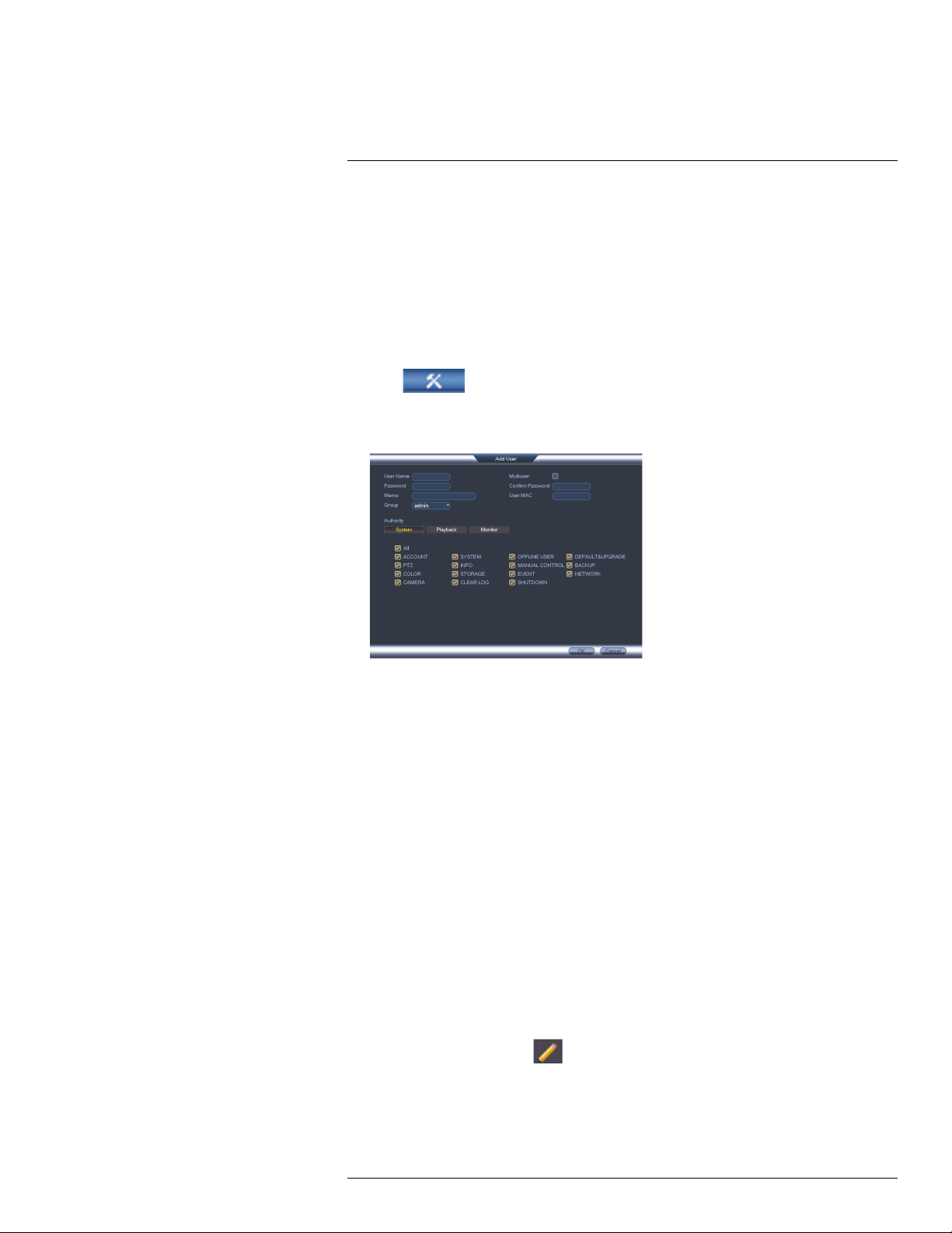
4. Click Add User.
5. Configure the following:
• User Name: Enter a name for the user account.
• Password: Enter a 6 character password for the user account. Enter the password
again under Confirm Password.
• Memo (optional): Enter a description of the user account.
• Group: Select the group you would like to assign to this user account. A user ac-
count cannot be given permissions its group does not have.
• Multiuser: Check to enable this user account to be used to login from more than
one device at the same time.
• Authority: Check the permissions you would like the user account to have. Under
the System tab, select the menus the user account may access. Under the Play-
back tab, select which channels the user account may access recorded video from.
Under the Covert tab, select the channels the user account may view live video
from.
• User MAC: Not supported. Leave this field blank.
6. Click OK to save changes.
Now, you can log in to the system locally, or remotely using the user name and password
you created. When logging into the system with a user account, the user will only have access to the menus you assigned.
15.3 Modifying Users
1. In the Account menu, click
next to the user account you would like to modify.
2. Update the user’s account details as needed, and then click OK to save changes.
#LX400028; r.27370/27370; en-US
38
Page 49

Managing Passwords and User Accounts15
15.4 Deleting Users
1. In the Account menu, click
next to the user account you would like to delete.
2. Click OK to confirm.
NOTE
The admin and default user accounts cannot be deleted from the system.
15.5 Account Groups
Account groups can be used to easily manage permissions for multiple user accounts.
User accounts can be given all the permissions of a group, but cannot be given permissions that the group does not have.
The system includes the following groups by default:
• admin: Accounts in the admin group are system administrators. They have full access
to the system, may configure all system settings, and can manage user accounts.
• user: Accounts in the user group are normal users. They have limited access to system
menus.
15.6 Adding Groups
1. From Live View, right-click and then select Main Menu.
2. If prompted, enter the system user name (default: admin) and password (default:
000000).
3. Click
and select Setting.
4. Click Account and select the Group tab.
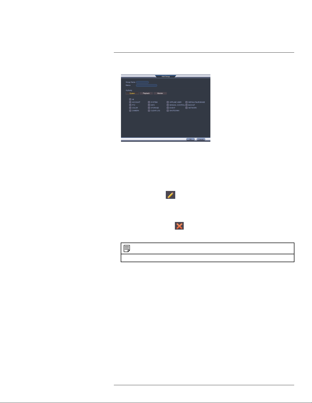
5. Click Add Group.
#LX400028; r.27370/27370; en-US
39
Page 50
Managing Passwords and User Accounts15
6. Configure the following:
• Under Group Name, enter a name for the group.
• Under Memo, enter an optional comment for this group.
• Under Authority, check the permissions that the group will have. User accounts as-
signed to this group can not be given any permissions the group does not have.
7. Click OK to save changes.
15.7 Modifying Groups
1. In the Group tab, click
next to the group you would like to modify.
2. Update the group’s details as needed, and then click OK to save changes.
15.8 Deleting Groups
1. In the Account menu, click
next to the user account you would like to delete.
2. Click OK to confirm.
NOTE
The admin and user groups cannot be deleted from the system.
#LX400028; r.27370/27370; en-US
40
Page 51

16
Using the Main Menu
To open the Main Menu:
• Using the Mouse: Right-click and click Main Menu.
NOTE
The system password may be required to access the Main Menu. By default the user name is admin
and the password is 000000.
1. SEARCH: Open Search/Playback mode. For details, see 13 Search (Playback), page
26.
2. BACKUP: Export files to USB device. For details, see 14 Backup, page 29.
3. CAMERA: Configure image settings, recording parameters, and titles for your
cameras.
4. INFO: View system information.
5. SETTING: Configure general system, schedule, network, recording, display, and motion settings. Restore system to factory defaults.
6. SHUTDOWN: Logout, restart, or shutdown the system.
16.1 Camera
The Camera menu allows you to configure image settings, recording parameters, and titles for your cameras.
NOTE
To change the image settings for your cameras, see 10.3 Adjusting Color Settings, page 18.
16.1.1 Recording
The Recording menu allows you to set recording parameters for your cameras, such as
the resolution and frame rate.
#LX400028; r.27370/27370; en-US
41
Page 52

Using the Main Menu16
16.1.2 Configuring Recording Quality
The system employs two video recording streams, a Main Stream and a Sub Stream. The
Main Stream records high quality video to your system’s hard drive. The Sub Stream records lower resolution video for efficient streaming to devices over the Internet. You can
customize the video quality settings for these streams according to your needs.
To configure recording quality:
1. From the Main Menu, click
and select Recording>Recording.
2. Select the camera you would like to configure.
3. Configure the following settings. Settings for the Main Stream are in the left column.
Settings for the Sub Stream are in the right column.
• Type: For the Main Stream, you can set different recording quality settings for Con-
tinuous, MD (Motion Detect), and Alarm recording. Select the type of recording you
would like to configure.
• Resolution: Select the resolution the selected camera will be recorded at. Higher
resolutions create a more detailed image, but take up more hard drive space to record and require more bandwidth to stream to connected computers or mobile
devices.
• Available resolutions for the Main Stream are: 1080P (1920x1080), 720P
(1280x720), 960H (960x480), D1 (704x480), HD1 (352X480), 2CIF (704x240),
CIF (352x240), and QCIF (176x120).
• Available resolutions for the Sub Stream are: D1 (704x480), CIF (352x240), and
QCIF (176x120).
• Frame Rate (FPS): Select the frame rate in Frames Per Second (FPS) that each
stream will record at. A higher frame rate provides a smoother picture, but requires
more storage and bandwidth.
• Bit Rate Type: Select CBR (Constant Bit Rate) or VBR (Variable Bit Rate) to deter-
mine the bit rate type. If you select VBR, you can set the video quality setting between 1 and 6. If you select VBR, select the Quality from 1 (lowest) to 6 (highest).
• Bit Rate (Kbps): Select the bit rate for each recording stream. A higher bit rate results in a better image, but increases the amount of hard drive space or bandwidth
required.
4. (Optional) Click the Copy button to copy recording settings to other channels.
5. Click OK to save changes.
16.1.3 Configuring Audio Recording
The system supports one channel of audio recording.
#LX400028; r.27370/27370; en-US
42
Page 53

Using the Main Menu16
NOTE
You must connect an RCA audio input device (such as a self-powered microphone; not included) to the
system to use audio recording. It is recommended to install the microphone near the camera for channel
1.
To configure audio recording:
1. From the Main Menu, click
and select Recording>Recording.
2. Under Channel, select 1.
3. Check the left Audio/Video checkbox to enable audio recording. Check the middle
checkbox to enable audio streaming to remote devices (such as a smartphone). Check
the right checkbox to enable video streaming to remote devices.
4. Under Audio Format, select the format that will be used to record audio. G711a is
recommended.
5. Under Audio Source, select Normal to use the system’s RCA audio input.
6. Click OK to save changes.
16.1.4 Configuring Snapshot Recording Settings
The system can be set to record snapshot images when a camera detects motion. These
snapshots can be viewed through the Search menu or can be attached to email alerts and
push notifications. The Snapshot tab in the Recording menu controls the quality and recording parameters for each camera.
NOTE
In order to enable Snapshot recording, the following menu options must be configured:
• The Snapshot schedule must be enabled for times that you would like to save snapshots. See 16.3.14
Configuring the Snapshot Schedule, page 61.
• Snapshot recording must be enabled for motion detection in the Event menu. See 16.3.7 Configuring
Motion Detection, page 55.
To configure snapshot recording settings:
1. From the Main Menu, click
and select Recording>Snapshot.
2. Under Snap Number, select the number of snapshots the system will take when the
snapshot button is pressed.
#LX400028; r.27370/27370; en-US
43
Page 54

Using the Main Menu16
3. Configure the following settings for snapshots saved automatically from motion detection or the snapshot schedule:
• Channel: Select the channel you would like to configure.
• Mode: Select Timing for the system to take snapshots according to the snapshot
schedule (see 16.3.14 Configuring the Snapshot Schedule, page 61) Select Trig-
ger for the system to take snapshots only when triggered by motion detection
(snapshot must be enabled in the Motion Detect menu (see 16.3.7 Configuring Mo-
tion Detection, page 55).
• Image Size: Select the resolution for snapshots.
• Image Quality: Select the snapshot image quality between 1 (lowest) and 6
(highest)
• Snapshot Frequency: Select the number of snapshots (up to 6) the system will
take each time.
4. Click OK to save changes.
16.1.5 Creating Custom Channel Names
You can assign custom names to your cameras. For example, you can name your cameras
based on their location (e.g. hallway or front door).
To create custom channel names:
1. From the Main Menu, click
and select Channel Name.
2. Enter a custom name for each channel.
3. Click OK to save changes.
#LX400028; r.27370/27370; en-US
44
Page 55
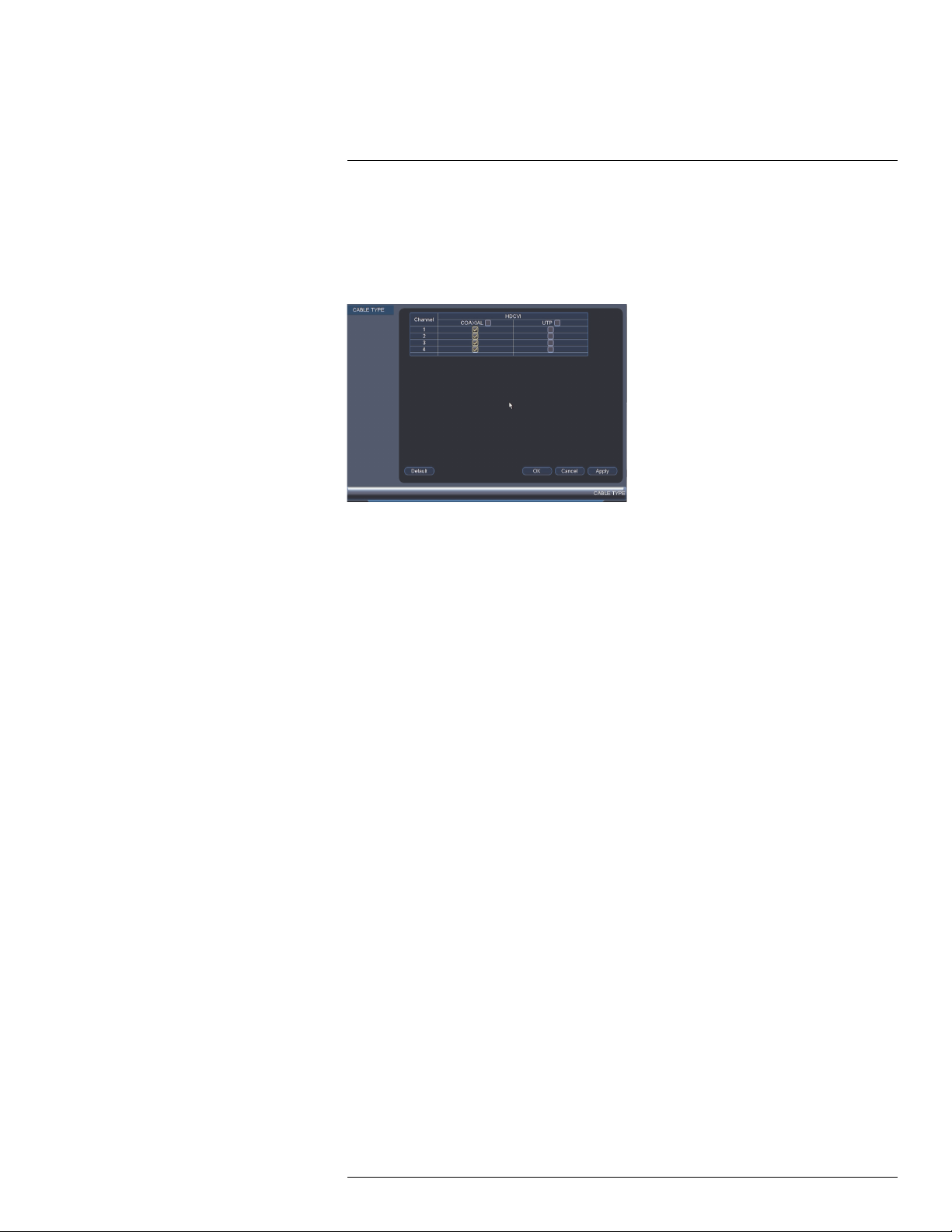
Using the Main Menu16
16.1.6 Selecting Cable Type
The Cable Type menu is used only if you are using cabling with a resistance higher than
10Ω per 100m (330ft) and you are having picture quality issues. Select the UTP option for
any channels having the issue. In all other installations, use the Coaxial setting. Click OK
to save your changes.
#LX400028; r.27370/27370; en-US
45
Page 56

Using the Main Menu16
16.2 Info
Info contains menus that show you system information.
16.2.1 HDD Info
The HDD Info sub-menu shows information related to the hard drives installed in the system, including capacity, status, and type.
To access the HDD Info menu:
• From the Main Menu, click
and then click Info.
16.2.2 Record Info
#LX400028; r.27370/27370; en-US
46
Page 57

Using the Main Menu16
The Record Info menu shows the start and end times of recordings saved on the hard
drive.
To access the Record Info menu:
• From the Main Menu, click
and then select Info>Record Info.
16.2.3 Version
The Version sub-menu allows you to view information about the current firmware installed
on the system.
To access the Version menu:
• From the Main Menu, click
and then click Info>Version.
16.2.4 Alarm Status
The Alarm Status menu shows you a display of system alarms. Activated alarms are highlighted in white. Additional info such as channels that are currently detecting motion is
shown.
The following alarms are shown in the Alarm Status menu:
• No HDD: No hard drive is detected.
• Disk Error: Hard drive error detected.
• Disk Full: Hard drive is full.
• Net Disconnection: System is not connected to the network.
• IP Conflict: More than one device on the network is using the same IP address.
• MAC Conflict: More than one device on the network is using the same MAC address.
• Local Alarm: Not supported.
• Net Alarm: Not supported.
#LX400028; r.27370/27370; en-US
47
Page 58
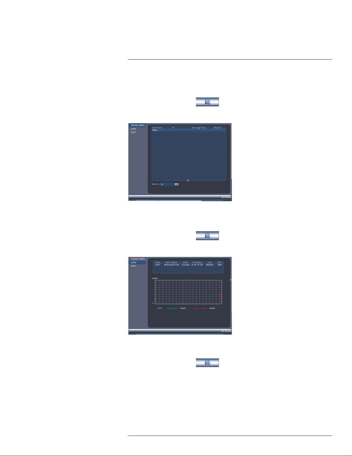
Using the Main Menu16
• Video Loss: Shows disconnected channels.
• Motion: Shows channels with active motion alarms.
To access the Alarm Status menu:
• From the Main Menu, click
and then select Alarm Status.
16.2.5 Online Users
The Online Users menu shows a list of users connected to the system using computers or
mobile devices.
To access Online Users:
• From the Main Menu, click and then select Network.
16.2.6 Load
The Load menu shows you the network traffic your system is sending and receiving.
To access Load:
• From the Main Menu, click
#LX400028; r.27370/27370; en-US
and then select Network>Load.
48
Page 59
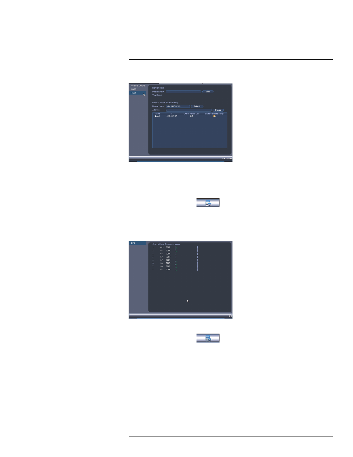
Using the Main Menu16
16.2.7 Test
The Test menu allows you to test if your system can connect to other devices over the LAN
or Internet. You can enter the IP address of a device and click Test to determine if your
system can connect to it.
To access Test:
• From the Main Menu, click
and then select Network>Test.
16.2.8 BPS
The BPS sub-menu shows the bitrates of connected cameras. The bitrate is the amount of
data the camera is sending to the system.
To access BPS:
• From the Main Menu, click
and then select BPS.
16.2.9 Log
The Log sub-menu allows you to search for system logs.
#LX400028; r.27370/27370; en-US
49
Page 60

Using the Main Menu16
To search for system logs:
1. From the Main Menu, click
and then select Log.
2. Under Type, select the log type to search for.
3. Under Start Time and End Time, select the start and end time for your search.
4. Click Search.
5. (Optional) Click Backup to export logs to a USB flash drive connected to the system.
#LX400028; r.27370/27370; en-US
50
Page 61

Using the Main Menu16
16.3 Setting
The Setting menu allows you to configure general system, schedule, network, recording,
display, and motion settings. It also allows you to restore the system to factory defaults.
16.3.1 Network
The Network menu allows you to configure network parameters for your system.
16.3.2 Selecting DHCP or Static IP Address (TCP/IP)
The TCP/IP menu allows you to configure IP address settings.
To configure IP address settings:
1. From the Main Menu, click
and then select Network>TCP/IP.
2. Under Mode, select DHCP (recommended) to let the system automatically obtain an
IP address from the router or Static to assign a static IP address.
If you select Static, configure the following:
• IP Address: Enter the IP address you would like to assign to the system. Make sure
that no other device on your network is using the same IP address.
• Subnet Mask: Enter the subnet mask for your network.
• Default Gateway: Enter the gateway address for your network.
• Preferred DNS: Enter the address of your primary DNS server.
• Alternate DNS: Enter the address of your secondary DNS server.
3. Click OK to save changes.
#LX400028; r.27370/27370; en-US
51
Page 62
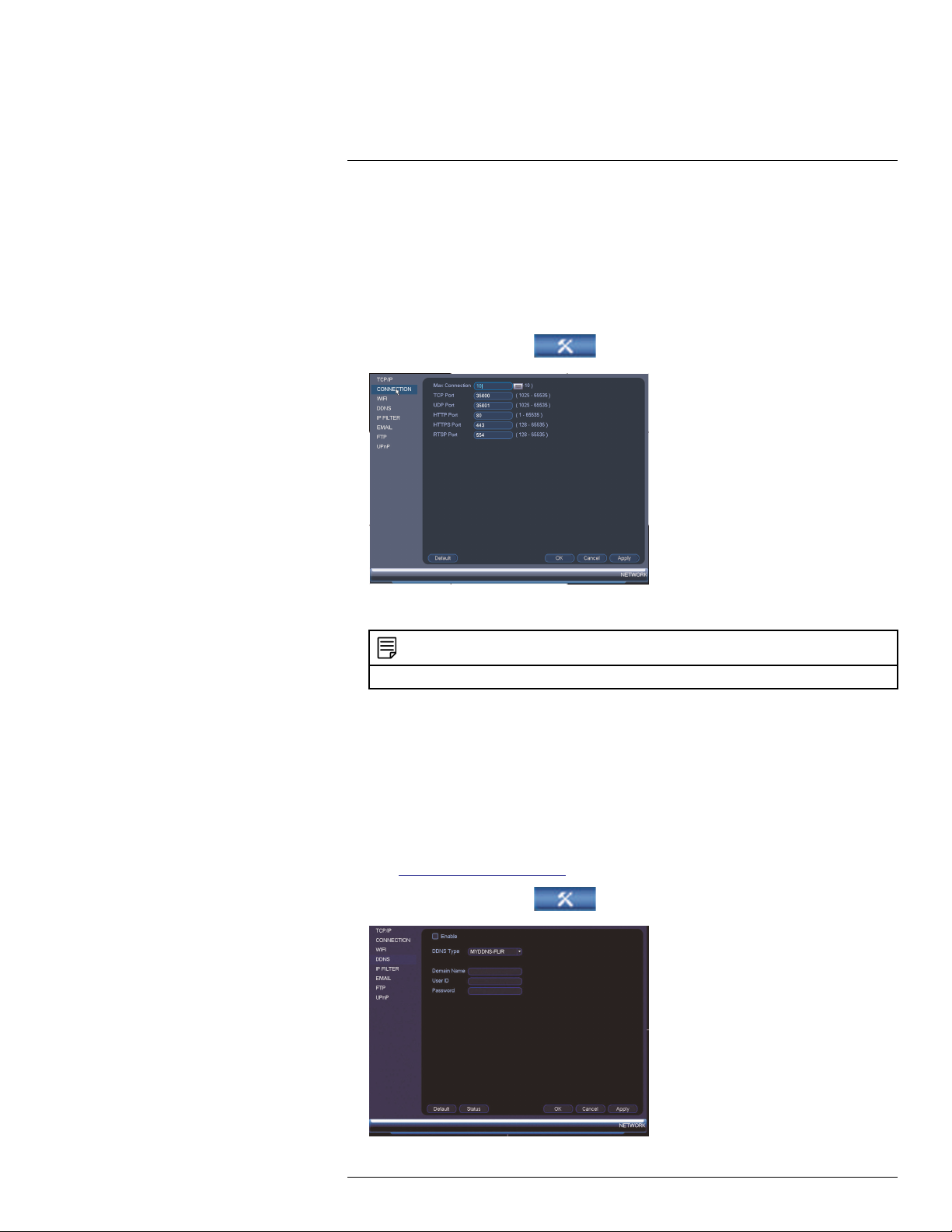
Using the Main Menu16
16.3.3 Configuring System Ports (Connection)
The Connection menu allows you to configure ports used by the system. Please note that
port forwarding is not required to use FLIR Cloud™ or to connect using the apps.
If you are using DDNS connectivity, port forwarding is required for the HTTP Port (defaut:
80) and TCP (Client Port) (default: 35000).
To configure system ports:
1. From the Main Menu, click
and then select Network>Connection.
2. Configure the ports as needed and click OK to save changes.
NOTE
Up to 3 devices may connect to the system at the same time when using FLIR Cloud™.
16.3.4 Configuring DDNS Settings
FLIR DDNS is available as an optional connectivity option. Please see 20 DDNS Setup
(Advanced), page 142 for details.
The primary connectivity option uses FLIR Cloud™ to connect to your system over the Internet without requiring port forwarding or DDNS registration. For details, see 17 Connect-
ing to Your System Over the Internet on PC or Mac, page 70.
To configure DDNS Settings:
1. Visit http://ddns.myddns-flir.com and register for a DDNS account.
2. From the Main Menu, click
#LX400028; r.27370/27370; en-US
and then select Network>DDNS.
52
Page 63

Using the Main Menu16
3. Check Enable.
4. Under Domain Name, enter the Domain Name/URL Request your received in the
email after registering for DDNS.
5. Under User Name, enter your DDNS User Name.
6. Under Password, enter your DDNS Device password.
7. Click OK to save your settings.
NOTE
Please allow 10~15 minutes for the DDNS servers to update with your new DDNS address before attempting to connect.
16.3.5 Configuring Email Alerts
You can configure the system to send out email alerts for motion detection or other events.
NOTE
To send out motion detection alerts, you must enable the Send Email option for motion detection on each
camera you would to receive alerts from. For details, see 16.3.7 Configuring Motion Detection, page 55.
To configure Email Alerts:
1. From the Main Menu, click
and then select Network>Email.
2. Check Enable to enable email notifications.
If you want to use FLIR’s email server (recommended):
1. Under Mail Select, select FLIR Mail to use the FLIR email server to send out alarm
notifications. This is the recommended setting.
#LX400028; r.27370/27370; en-US
53
Page 64
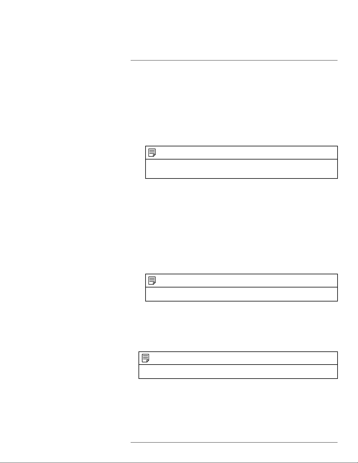
Using the Main Menu16
2. Configure the following:
• EmailSchedule: Click Setup and select the days you want email alerts to be
enabled.
• Receiver: Enter the email address that will receive alerts.
• Sender: Enter the sender’s email address.
• Subject: Enter the subject line for the email alert.
• Interval: Enter the interval between alert emails.
• Health Enable: Check to enable health check emails. Health check emails will be
sent periodically to ensure that the system is functioning normally. If you enable
health check emails, enter the Interval in minutes below.
NOTE
You must enable the Snapshot option for motion detection on each camera you would to receive
a jpg image attachment of the camera image. For details, see 16.3.7 Configuring Motion Detec-
tion, page 55.
3. Click Test to send a test email.
4. Click OK to save settings.
If you want to use Gmail or Yahoo Mail:
1. Under Mail Select, select Gmail or Yahoo Mail.
2. Configure the following:
• Anonymous: Check if your server supports anonymous log ins. Otherwise, leave
this unchecked.
• User Name: Enter your Gmail or Yahoo Mail user name.
• Password: Enter your Gmail or Yahoo Mail password.
• Receiver: Enter the email address that will receive alerts.
• Sender: Enter the sender’s email address.
• Subject: Enter the subject line for the email alert.
NOTE
You must enable the Snapshot option for motion detection on each camera you would to receive
attachments. For details, see 16.3.7 Configuring Motion Detection, page 55.
• Event Interval: Enter the interval between alert emails.
• Health Enable: Check to enable health check emails. Health check emails will be
sent periodically to ensure that the system is functioning normally.
• Interval: Enter the interval in minutes for health check emails.
3. Click Test to send a test email.
4. Click OK to save settings.
NOTE
Gmail and Yahoo Mail are not supported by FLIR. Gmail and Yahoo Mail SMTP information may
change. Contact Google or Yahoo for support.
If you want to use your own email server (advanced):
1. Under Mail Select, select Custom.
#LX400028; r.27370/27370; en-US
54
Page 65

Using the Main Menu16
2. Configure the following:
• SMTP Server: Enter the SMTP server address.
• Port: Enter the port used by the SMTP server.
• Anonymous: Check if your server supports anonymous log ins. Otherwise, leave
this unchecked.
• User Name: Enter the SMTP user name.
• Password: Enter the SMTP password.
• Receiver: Enter the email address that will receive alerts.
• Sender: Enter the sender’s email address.
• Subject: Enter the subject line for the email alert.
• Attachment: Check to include a jpg image attachment of the camera.
NOTE
You must enable the Snapshot option for motion detection on each camera you would to receive
attachments. For details, see 16.3.7 Configuring Motion Detection, page 55.
• Encrypt Type: Select SSL or TLS if your server uses encryption. Select None if
your server does not use encryption.
• Event Interval: Enter the interval between alert emails.
• Health Enable: Check to enable health check emails. Health check emails will be
sent periodically to ensure that the system is functioning normally.
• Interval: Enter the interval in minutes for health check emails.
3. Click Test to send a test email.
4. Click OK to save settings.
16.3.6 Event
The Event menu allows you to configure settings for motion detection, video loss, and system warnings.
16.3.7 Configuring Motion Detection
Motion Detection events allow the system to mark footage that has motion. This allows
you to quickly locate relevant footage through Search. You can also configure system responses to motion detection events, such as activating the system buzzer or sending an
email alert.
To configure Motion Detection events:
1. From the Main Menu, click
and then click Event>Motion>Motion Detect.
2. Under Channel, select the channel you would like to configure.
#LX400028; r.27370/27370; en-US
55
Page 66
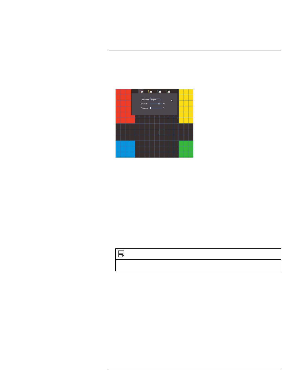
Using the Main Menu16
3. Check Enable to enable motion detection on the selected channel.
4. Click Setup next to Region to configure which areas of the image will be enabled for
motion detection. A grid will appear on the monitor.
Motion Grid
• Areas enabled for motion detection are shown in color and areas that are disabled
are transparent.
• You can set up to 4 motion detection areas and customize the sensitivity and thresh-
old for motion detection separately for each one. Hover the mouse at the top of the
screen to select which motion area you would like to configure.
• Right-click when finished.
5. Under Anti-dither, enter the anti-dither time. After a motion event occurs and motion
stops, if motion is detected within the anti-dither time, the system continues the motion
event and includes the new motion within the first event, rather than creating a new
motion event.
6. Under Post_REC, enter the time the system will record after a motion event occurs.
7. To configure a schedule when motion detection will be enabled on this channel, click
Setup next to Period. Configure times when motion detection will be enabled. For example, you may want to disable motion detection during business hours and enable it
outside of business hours. Click OK when finished.
NOTE
This setting can override scheduled motion recording. This means that motion recording will only
take place at times that are enabled both in the Schedule menu and here.
8. Configure the following system actions when motion is detected:
• Show Message: Check to enable an on-screen pop-up when one of your cameras
detects motion. On-screen pop-up shows the channels an event occurred on and
the type of event.
• Alarm Upload: Check to enable the system to upload alerts to FLIR Cloud™ Client.
• Send Email: Check to enable email alerts. You must configure email alerts before
you will be able to receive them (see 16.3.5 Configuring Email Alerts, page 53).
• Record Channel: Select the channels that will record when motion is detected on
the selected channel.
• Buzzer: Check to enable the system buzzer.
• Snapshot: Check to save a snapshot when the camera detects motion.
9. Click OK to save changes.
#LX400028; r.27370/27370; en-US
56
Page 67
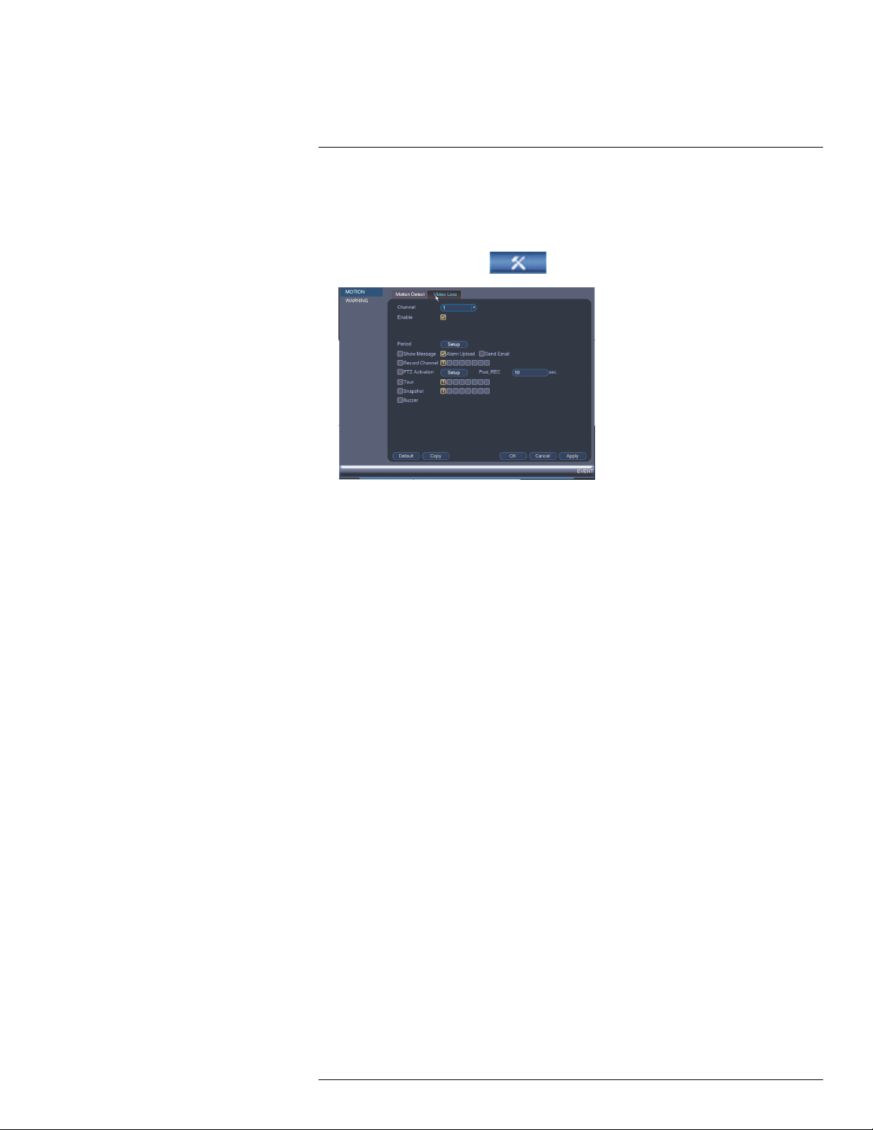
Using the Main Menu16
16.3.8 Configuring Video Loss Settings
Video Loss occurs if the system loses connection to one of the cameras.
To configure Video Loss settings:
1. From the Main Menu, click
and then click Event>Motion>Video Loss.
2. Under Channel, select the channel you would like to configure.
3. Check Enable to enable video loss events for the selected channel.
4. Configure the following to customize settings for video loss events:
• Period: Click Setup to configure a schedule for video loss events. It is recom-
mended to leave this on the default setting, so you can be alerted at any time one of
your cameras loses video.
• Show Message: Check to show a popup message on the monitor if one of your
cameras loses video.
• Send Email: Check to enable email alerts. You must configure email alerts before
you will be able to receive them (see 16.3.5 Configuring Email Alerts, page 53).
• Record Channel: Click the checkbox to enable video recording when video loss
occurs. You can then select the channels the system will record when video loss occurs on the currently selected channel.
• Post_REC: Enter the number of seconds the system will record after video loss
occurs.
• Snapshot: Click the box to enable snapshot recording when video loss occurs. You
can then select which channels will save snapshots when video loss occurs on the
currently selected channel.
• Buzzer: Check to enable the system buzzer when video loss occurs on the cur-
rently selected channel.
5. Click OK to save changes.
16.3.9 Configuring Hard Drive Warnings
Hard drive warnings will notify you if an issue is detected with the hard drive.
#LX400028; r.27370/27370; en-US
57
Page 68

Using the Main Menu16
To configure hard drive warnings:
1. From the Main Menu, click
and then click Event>Warning>HDD.
2. Under Event Type, select the hard drive event you would like to configure.
• No Disk: No hard drive detected.
• Disk Error: A hard drive error has been detected.
• Disk Full: The hard drive is full or almost full. You can enter the percentage of disk
space remaining that will trigger a warning under Less Than (e.g. when less than
10% of the hard drive is empty, trigger a warning). Disk Full warnings will not occur if
overwrite is enabled.
• All: Configure warnings for all hard drive events.
3. Configure the responses the system will take when the selected event occurs:
• Show Message: Show a popup message on the monitor.
• Send Email: Check to enable email alerts. You must configure email alerts before
you will be able to receive them (see 16.3.5 Configuring Email Alerts, page 53).
• Buzzer: Check to activate the system buzzer.
4. Click OK to save changes.
16.3.10 Configuring Network Warnings
Network warnings will notify you if your system loses connection to the Internet or local
network or if there is an issue on your network.
To configure network warnings:
1. From the Main Menu, click
#LX400028; r.27370/27370; en-US
and then click Event>Warning>Network.
58
Page 69

Using the Main Menu16
2. Under Event Type, select the event type you would like to configure.
• Net Disconnection: The system has lost connection to the network.
• IP Conflict: More than one device on your network has the same IP address.
• MAC Conflict: More than one device on your network has the same MAC address.
• All: Configure responses for all network events.
3. Configure the following for the selected event type:
• Enable: Check to enable the selected event type.
• Show Message: Check to show a popup message when the selected event occurs.
• Send Email: Check to enable email alerts. You must configure email alerts before
you will be able to receive them (see 16.3.5 Configuring Email Alerts, page 53).
• Buzzer: Check to activate the system buzzer.
• Record Channel: If Net Disconnect is selected, you can set the system to trigger
recording after it loses connection to the network. Check Record Channel to enable video recording and select the channels you would like to record. Set the
amount of time you would like the system to record under Post_REC.
4. Click OK to save changes.
16.3.11 Storage
The Storage menu allows you to configure the recording schedule and hard drives connected to the system.
16.3.12 Configuring the Video Recording Schedule
You can set a custom recording schedule according to your needs. For example, you can
set the system to record continuously during business hours and record on motion detection only outside of business hours.
A custom recording schedule helps reduce the amount of hard drive space required, increasing the time your system can retain recordings.
To configure the video recording schedule:
1. From the Main Menu, click
and then click Storage>Schedule>Record.
2. Under Channel, select the channel you would like to configure or select All.
#LX400028; r.27370/27370; en-US
59
Page 70

Using the Main Menu16
3. Configure the schedule as needed:
• Check Continuous or MD (motion detection) to select the recording type you would
like to configure.
• Click and drag on each day to customize the recording schedule. The schedule is
set up as a grid, which each block representing one hour.
• Click
changes to
next to All to link the recording schedules for all days. The icon for a day
when days are linked. You can also click the boxes next to individual days to link them to each other. If the recording schedule is linked, changes
made to one of the days will apply to every day that is linked.
• Click
• Click
to disable all recording of the selected type on the selected day.
if you need to set a more precise schedule down to the minute.
4. Click OK to save changes.
16.3.13 Configuring Pre-Recording
The system can pre-record video when motion detection events occur.
To configure pre-recording:
1. From the Main Menu, click
and then click Storage>Schedule>Record.
2. Under Channel, select the camera you would like to configure or select All.
3. Under PreRecord, select the duration for pre-recording.
4. Click OK to save settings.
#LX400028; r.27370/27370; en-US
60
Page 71

Using the Main Menu16
16.3.14 Configuring the Snapshot Schedule
You can set a schedule for recording snapshots from the cameras.
To set up the snapshot schedule:
1. From the Main Menu, click
and then click Storage>Schedule>Snapshot.
2. Under Channel, select the channel you would like to configure or select All.
3. Configure the schedule as needed:
• Check Continuous or MD (motion detection) to select the recording type you would
like to configure.
• Click and drag on each day to customize the recording schedule. The schedule is
set up as a grid, which each block representing one hour.
• Click
changes to
next to All to link the recording schedules for all days. The icon for a day
when it is linked. You can also click the boxes next to individual
days to link them to each other. If the recording schedule is linked, changes made
to one of the days will apply to every day that is linked.
• Click
• Click
to disable all recording of the selected type on the selected day.
if you need to set a more precise schedule down to the minute.
4. Click OK to save changes.
16.3.15 Configuring Holidays
You can set certain days as holidays. Holidays have a special recording schedule.
#LX400028; r.27370/27370; en-US
61
Page 72

Using the Main Menu16
To configure holidays:
1. From the Main Menu, click
2. Click Add New Holidays.
3. Configure the following:
and then click Setting>General>Holiday.
• Holiday Name: Enter a name for this holiday.
• Repeat Mode: Select Once Only for the holiday to occur only this year or All-Year
for the holiday to be repeated each year.
• Holiday Range: Select Date to select a specific date, or select Week to select holidays based on which week they fall on.
4. Click Add. Now that you have added a holiday, an extra holiday setting is added to the
recording schedule.
NOTE
You cannot delete holidays, but you can disable them by selecting Stop under the Status drop-down
and then click Apply.
16.3.16 Formatting the Hard Drive
The HDD Manager menu allows you to format the hard drive. If you install a new hard
drive, you must format the hard drive using the system before you will be able to record.
To format the hard drive:
CAUTION
Formatting the hard drive erases all data on the hard drive. This step cannot be undone.
#LX400028; r.27370/27370; en-US
62
Page 73

Using the Main Menu16
1. From the Main Menu, click
and then click Storage>HDD Manager.
2. Select the hard dive you would like to format and then click Format. Click OK to
confirm.
3. Click OK to save changes. The system will restart to complete the formatting process.
16.3.17 Configuring Hard Drive Type
The system supports the following hard drive types:
• Read-write HDD: Normal recording hard drive.
• Read-only HDD: The system can playback data from this hard drive, but it will not re-
cord to it.
To set the hard drive type:
1. From the Main Menu, click
and then click Storage>HDD Manager.
2. Click the hard drive you would like to configure.
3. Under Type, select Read-write HDD or Read-only HDD.
4. Click OK to save changes. The system will restart to complete this operation.
16.3.18 Configuring General System Settings
You can use the General menu to configure miscellaneous system settings.
#LX400028; r.27370/27370; en-US
63
Page 74
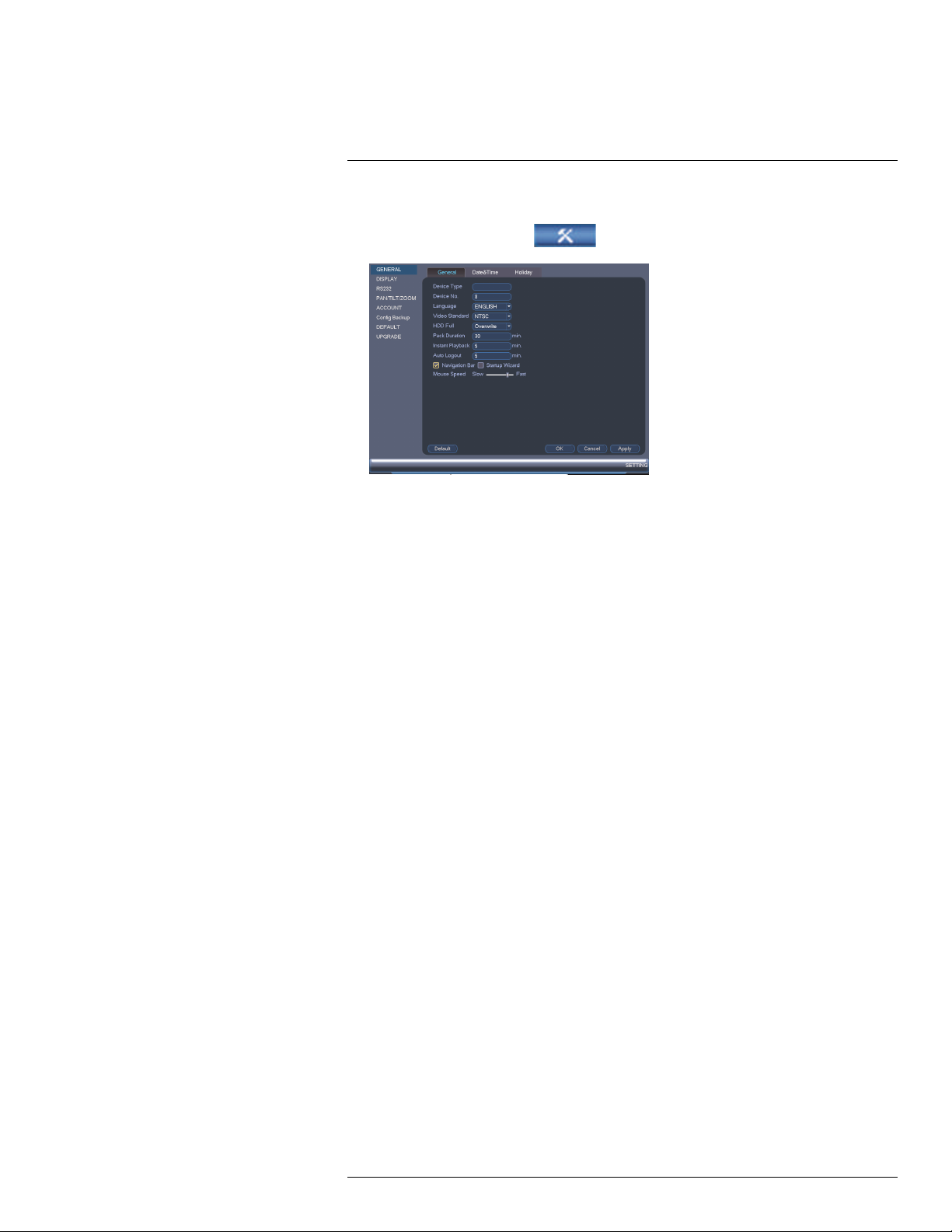
Using the Main Menu16
To configure general settings:
1. From the Main Menu, click
and then click Setting>General>General.
2. Configure the following:
• Device Type: Shows the model number of your system.
• Device No.: Select the remote control address of the system. See 9.1 Setting the
Remote Control Address, page 16.
• Language: Set the system languages. Available options are English, French, and
Spanish.
• Video Standard: Select NTSC (North America) or PAL (Europe).
• HDD Full: Select Overwrite for the system to overwrite the oldest recordings when
the hard drive is full or select Stop Record for the system to stop recording when
the hard drive is full.
• Pack Duration: Select how the duration (in minutes) the system will store video
files. For example, if this is set to 30 minutes, the system will create a new video file
for each 30 minutes of continuous recording.
• Instant Playback: Select the amount of time (in minutes) the system will go back
when instant playback is activated in live view.
• Auto Logout: Select the idle time (in minutes) before the system will logout the cur-
rent user.
• Navigation Bar: Check to enable the Navigation Bar that comes up when you left
click in live view.
• Startup Wizard: Check to enable a setup wizard when you start up the system.
• Mouse Speed: Use the slider to adjust the mouse speed.
3. Click OK to save changes.
16.3.19 Setting the Monitor Resolution (Display)
The Display menu allows you to configure the systems monitor resolution and other display settings.
#LX400028; r.27370/27370; en-US
64
Page 75
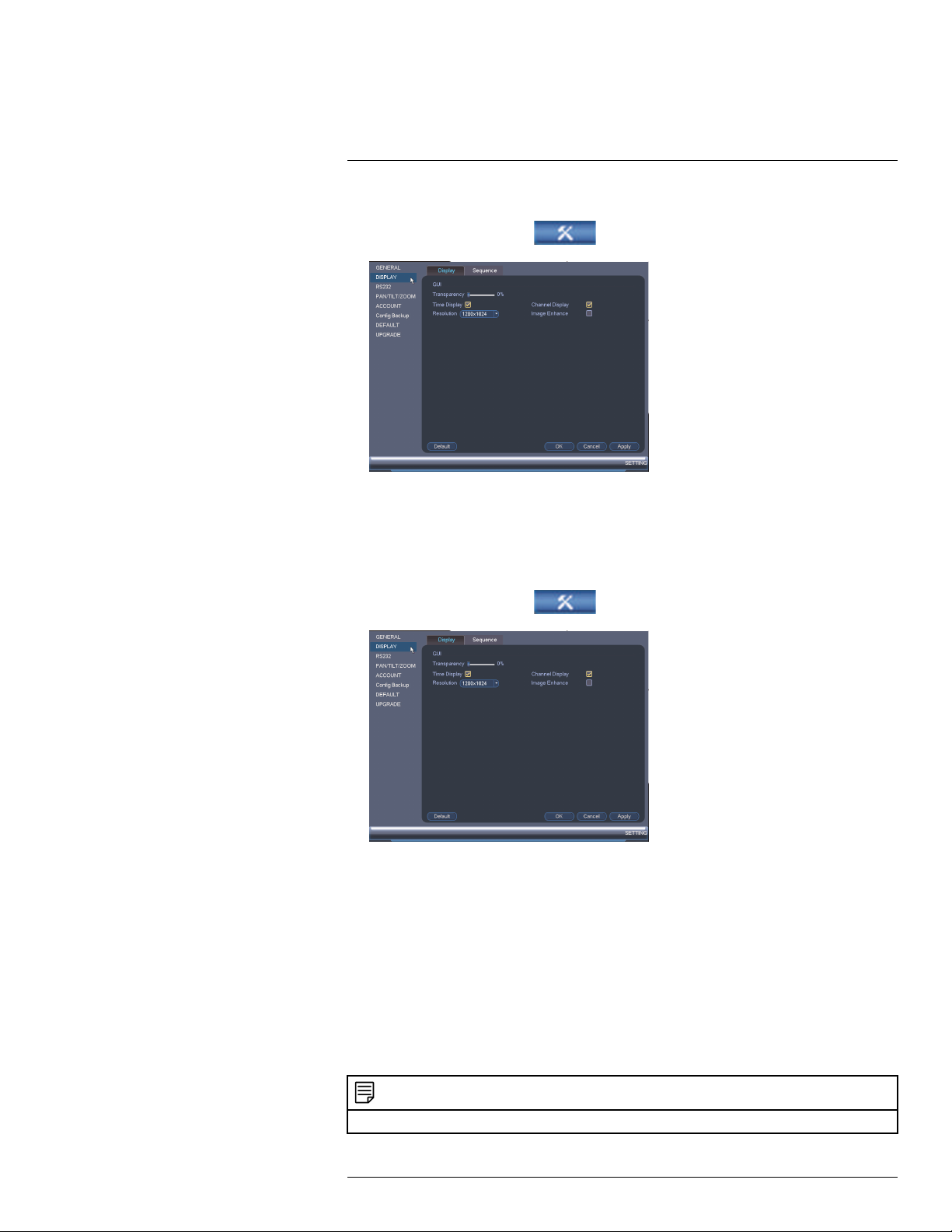
Using the Main Menu16
To set the monitor resolution:
1. From the Main Menu, click
and then click Setting>Display>Display.
2. Under Resolution, select the correct resolution for your monitor: 1920x1080,
1280x1024, 1280x720, or 1024x768.
3. Click OK to save changes. Click OK again to restart the system using the new
resolution.
To configure other display settings:
1. From the Main Menu, click
and then click Setting>Display>Display.
2. Configure the following:
• Transparency: Select the menu transparency.
• Time Display: Check to show the time on the monitor.
• Channel Display: Check to show the channel names on the monitor.
• Image Enhance: Check for the system to digitally improve the video quality on the
live display. This setting does not affect recordings.
3. Click OK to save changes.
16.3.20 Saving Your System Configuration to a USB Flash Drive
The system allows you to save your current system configuration to a USB flash drive (not
included). This is useful if you want to backup your current settings.
NOTE
This function only saves settings created in system menus. It does not save or backup any video.
#LX400028; r.27370/27370; en-US
65
Page 76

Using the Main Menu16
To save your system configuration to a USB flash drive:
1. Insert a USB flash drive (not included) into one of the USB ports.
2. From the Main Menu, click
and then click Setting>Config Backup.
3. Under Device Name, select the USB device where you would like to save the
configuration.
4. Click Export to save your current system configuration.
To restore a saved system configuration:
1. Insert a USB flash drive (not included) with a saved system configuration into one of
the USB ports.
2. From the Main Menu, click
and then click Setting>Config Backup.
3. Under Device Name, select the USB device.
4. Click the folder with the configuration files you would like to restore. Configuration file
folders are labeled “Config” and then the time and date the configuration was saved (e.
g. Config_20140425103727).
5. Click Import to restore the system configuration.
6. Click OK to confirm. The system will restart to complete the operation.
16.3.21 Setting the System to Factory Defaults
The Default menu allows you to reset the system to factory default settings.
#LX400028; r.27370/27370; en-US
66
Page 77
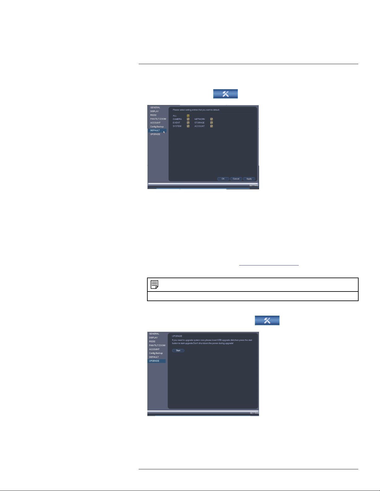
Using the Main Menu16
To reset the system to factory default settings:
1. From the Main Menu, click
and then click Setting>Default.
2. Check the menus you would like to reset to default settings.
3. Click OK.
16.3.22 Upgrading Firmware from USB
Firmware upgrades provide enhanced functionality. The system will automatically check
for firmware upgrades if it is connected to the Internet. The system also supports firmware
upgrades from a USB thumb drive (not included).
To upgrade firmware from a USB drive:
1. Download the firmware upgrade from www.flirsecurity.com/pro.
2. Extract the firmware file and copy the firmware to a blank USB flash drive.
NOTE
Do not have any folders on the USB flash drive—just the firmware file.
3. Insert the USB flash drive to a USB port on the system.
4. Right-click and then click Main Menu. Click
5. Click Start.
>Setting>Upgrade.
#LX400028; r.27370/27370; en-US
67
Page 78

Using the Main Menu16
6. Select the firmware file on the USB drive and click Start.
WARNING
DO NOT POWER OFF THE SYSTEM OR DISCONNECT THE POWER CABLE DURING FIRMWARE INSTALLATION
#LX400028; r.27370/27370; en-US
68
Page 79

Using the Main Menu16
16.4 Shutdown
Use the Shutdown menu to shutdown, restart, or log out of the system.
To access the Shutdown menu:
1. From live view, right-click and select Main Menu.
2. Enter the system User Name (default: admin) and Password (default: 000000) and
click OK.
3. Click
>Shutdown.
4. Select one of the following:
• Logout: Log out the account that is currently active.
• Shutdown.
• Restart.
#LX400028; r.27370/27370; en-US
69
Page 80

17
Connecting to Your System Over the Internet on PC or Mac
This system features connectivity using the exclusive FLIR Cloud™. This cloud-enabled
service allows for Internet connectivity without requiring any network configuration. Up to 3
devices may connect to the system at the same time.
NOTE
• Except where noted, the PC and Mac instructions in this section are the same.
• For smartphone/tablet setup, see 19 Connecting to your System Using Smartphone or Tablet Apps,
page 101.
• For the latest list of supported apps and devices, visit www.flirsecurity.com/pro.
17.1 System Requirements
Your system must meet the system requirements below:
Description Requirement
CPU Core 2 Duo 3.0GHz
Operating System Windows™ 8/7/Vista
Mac OSX 10.7 and above
Memory
Video 512 MB of video memory and above
Network (LAN) 10/100 BaseT Network
Network (WAN) 1 Mbps upstream
17.2 Step 1 of 3: Connect your System to Your Router
1. Power off your system by disconnecting the power adapter.
2. Connect an Ethernet cable (included) to the LAN port on the rear panel of the system.
Connect the other end of the Ethernet cable to an empty LAN port (usually numbered
1~4) on your router.
2GB
High-speed Internet service is required to remotely
connect to your system.
#LX400028; r.27370/27370; en-US
70
Page 81
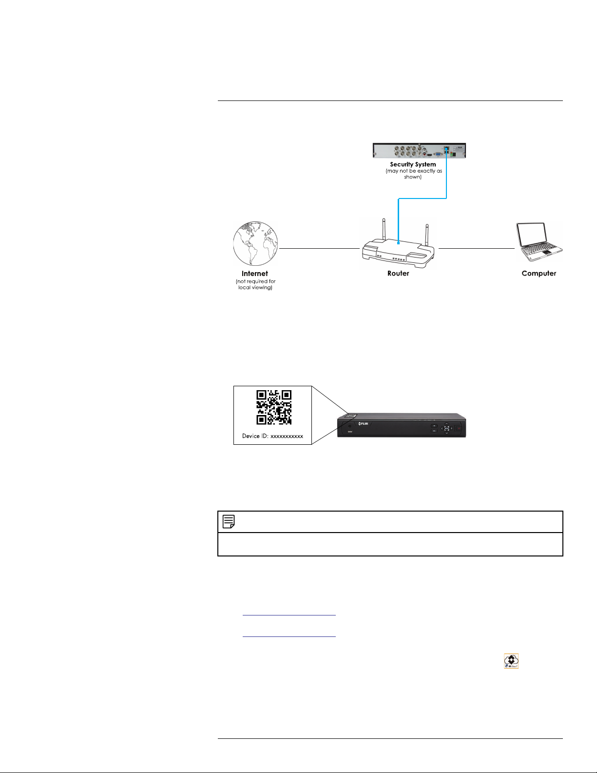
17
Connecting to Your System Over the Internet on PC or Mac
3. Reconnect the power adapter to power the system back on.
17.3 Step 2 of 3: Obtain the system’s Device ID
The Device ID is a unique code that allows your system to handshake with FLIR Cloud™
servers for a secure connection over the Internet.
To find the Device ID:
1. The Device ID is located on a sticker on the system.
2. Write down the Device ID of the system.
17.4 Step 3 of 3: Connect to the System Over the Internet
Follow the steps below to connect to the system over the Internet.
NOTE
Make sure to upgrade your system to the latest firmware version. You must have the latest firmware
and client software to connect to the system over the Internet.
To connect to the system over the Internet:
1. Download and install the client software.
• PC Users: Download and install the Client Software for PC from
www.flirsecurity.com/pro.
• Mac Users: Download and install the Client Software for Mac from
www.flirsecurity.com/pro. Double click to extract the software. Then, drag the soft-
ware to Applications.
2. Once installation is finished, double-click the FLIR Cloud™ Client icon (
) from the
desktop or Applications list.
#LX400028; r.27370/27370; en-US
71
Page 82

17
Connecting to Your System Over the Internet on PC or Mac
3. Log into the Client Software using the Client Software user name (default: admin) and
password (default: admin) and then click Login.
4. Click Add Device.
5. Enter the following:
#LX400028; r.27370/27370; en-US
72
Page 83

17
Connecting to Your System Over the Internet on PC or Mac
5.1. Device Name: Choose a name for your system of your choice.
5.2. Device ID: Manually enter the Device ID printed on the label.
5.3. Client Port: Enter the Client Port (default: 35000).
5.4. User Name: Enter the system User Name (default: admin).
5.5. Password: Enter the system Password (default: 000000).
6. Click Add. If this is the first time you are connecting, you will be prompted to change
the system password.
7. Enter a new 6 character password and click OK. This password will be used to connect to your system from now on.
8. Click then .
#LX400028; r.27370/27370; en-US
73
Page 84

17
Connecting to Your System Over the Internet on PC or Mac
9. Click and drag Default Group to the display window to open your cameras in live view.
Congratulations! You can now connect over the Internet to view and playback video
on your computer.
#LX400028; r.27370/27370; en-US
74
Page 85

18
Using FLIR Cloud™ Client for PC or Mac
FLIR Cloud™ Client allows you to connect to multiple systems from a PC or Mac.
18.1 Home Page
The Home Page allows you to access all the tabs within the software. Each tab allows you
to access different features.
To open tabs:
Click a tab from the Home Page to open it or click the
from within any tab to open a new tab.
18.2 Live View
The Live View tab is where you can view live video from connected systems.
To view live video from a system:
1. Click
2. Click and drag a DVR, NVR, group, or individual camera to open live video. To access
individual cameras, you can click + to expand groups or systems.
and then click to create a Live View tab.
button at the top of the screen
#LX400028; r.27370/27370; en-US
75
Page 86

18
Using FLIR Cloud™ Client for PC or Mac
18.2.1 Live View Controls
1. Live display: Double-click to expand the area. Right-click to access additional options.
Hold the mouse over the display area to access the camera toolbar.
Camera toolbar:
1.1. Streaming quality: Shows the bitrate and resolution for the stream, and shows
if display is showing the Sub Stream or Main Stream.
1.2. Manual recording: Click to start/stop manual recording.
1.3. Snapshot: Click to save a snapshot.
1.4. Mute/unmute: Click to mute/unmute audio (audio camera required).
1.5. Not supported.
1.6. Instant playback: Plays back the most recently recorded video from the cam-
era. By default, it will play back the last 5 minutes of recorded video from the
camera.
1.7. Digital zoom: Click to enable digital zoom mode. Click and drag over the dis-
play area to zoom on the camera. Then click and drag to pan. Click the icon
again to zoom out.
1.8. Disconnect.
1. Split-screen mode: Click to select split-screen layout.
2. Aspect ratio: Use the drop down menu to select the aspect ratio for the selected
camera. Original uses the actual aspect ratio of the image. Full-win stretches the im-
age to fill up the entire display area.
#LX400028; r.27370/27370; en-US
76
Page 87

18
Using FLIR Cloud™ Client for PC or Mac
3. Full-screen: Click to open full-screen mode. Press ESC to exit full-screen mode.
4.
Save view: Click to save the current display layout and open cameras as a view.
Then enter a name for the view.
5.
Start/stop tour: Click to start the tour. During the tour the client will cycle through
all saved views every few seconds. Click again to stop the tour.
6. PTZ Controls: Controls for PTZ cameras (not included). See 18.3 Controlling PTZ
Cameras, page 78 for details.
7. View: Click View to access view menu. Then double-click on a view to open it in the
display area.
8. Devices: Shows a list of groups, cameras, and systems connected to the client. Drag
items to the display area to open live video. Right-click to view additional options.
18.2.2 Opening Live View in Multiple Monitors
If your computer has multiple monitors, you can open more than one Live View tab and
move them to secondary monitors. This allows you to monitor cameras on multiple monitors at the same time.
NOTE
Using multiple monitors significantly increases the amount of computing resources necessary to run the
application and may affect performance.
To open Live View in multiple monitors:
1. Click
and then click to create a Live View tab.
#LX400028; r.27370/27370; en-US
77
Page 88

18
Using FLIR Cloud™ Client for PC or Mac
2. Click and drag the tab outside of the client window to create a new window. You can
drag the window to one of the secondary monitors.
Result
18.3 Controlling PTZ Cameras
If you have PTZ cameras (not included), you can control them using the client.
NOTE
You must ensure the PTZ camera is properly connected to your system and your system is configured to
detect it before you can control them using the client.
To control PTZ cameras:
• Click the display area with the PTZ cameras and use the on-screen PTZ controls.
#LX400028; r.27370/27370; en-US
78
Page 89
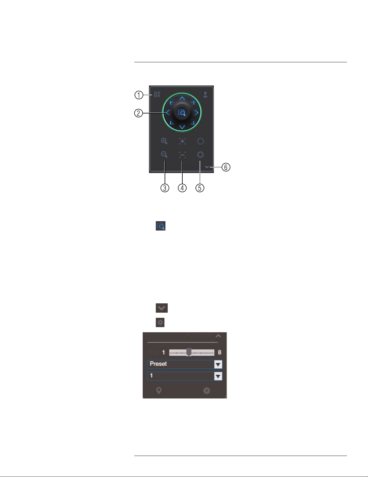
18
Using FLIR Cloud™ Client for PC or Mac
PTZ controls:
1. Open menu: Click to open camera OSD menu controls. This feature may not be supported for all camera models.
2. Move camera: Click the arrows to move the camera.
Click
to open dynamic zoom mode. Then click and drag in the video area to zoom
in the camera on an area.
3. Zoom +/-: Click to zoom the camera in and out.
4. Focus +/-: Click to increase/decrease the focus.
5. Iris +/-: Click to increase/decrease the iris.
6. Advanced: Click to access advanced PTZ controls.
18.3.1 PTZ Presets
Presets will save a camera position for quick retrieval.
To add presets:
1. Click
2. Click
to open the Advanced controls. Select Preset.
.
#LX400028; r.27370/27370; en-US
79
Page 90
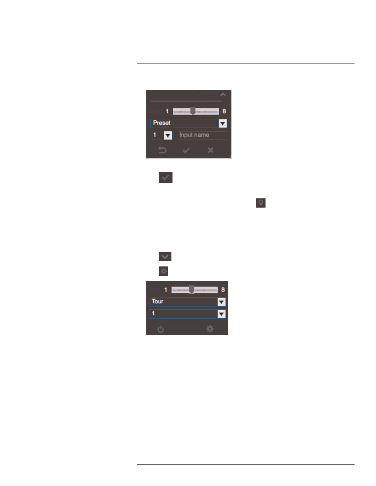
18
Using FLIR Cloud™ Client for PC or Mac
3. Select the number of the preset you would like to add.
4. Move the camera to the desired position.
5. Click
to save the current position as a preset.
To go to a saved preset:
1. Select the preset number from the list or click
to go to the currently selected
preset.
18.3.2 PTZ Tours
Tours will cycle through a set of presets.
To configure a PTZ tour:
1. Click
2. Click
to open the Advanced controls. Select Tour.
.
3. Under Cruise ID, select the number of the tour you would like to configure.
4. (Optional) Under Cruise Name, enter a name for the tour.
#LX400028; r.27370/27370; en-US
80
Page 91
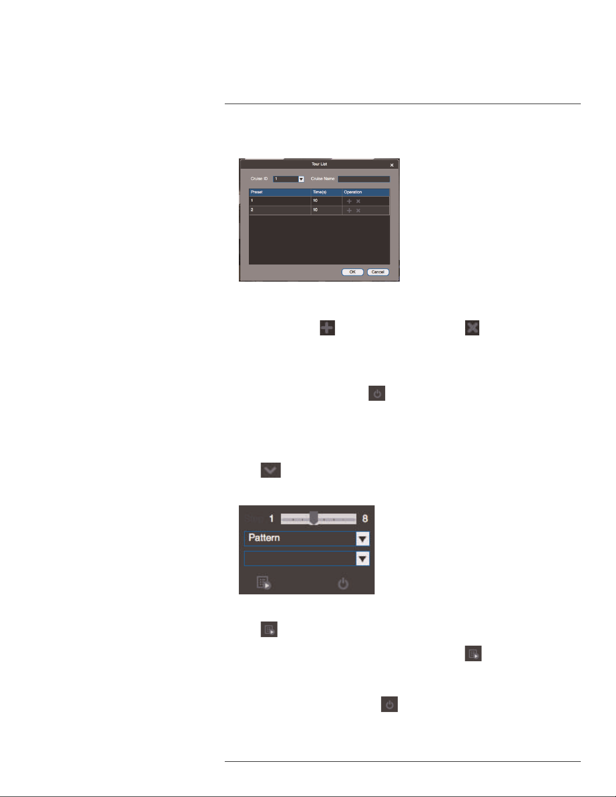
18
Using FLIR Cloud™ Client for PC or Mac
5. Use the chart to select which presets you would like to include in the tour and the order
of presets.
• Preset: Select the preset number.
• Time(s): Enter the time in seconds the camera will remain on the selected preset.
• Operation: Click
to add a preset to the tour. Click to delete a preset from
the tour.
6. Click OK to save changes.
To run a PTZ tour:
1. Select the tour number and click
.
18.3.3 PTZ Pattern
Patterns automatically cycle the camera between two positions.
To create a pattern:
1. Click
to open the Advanced controls. Select Pattern.
2. Select the number of the pattern you would like to set up.
3. Move the camera into the desired start position.
4. Click
to start recording the pattern.
5. Move the camera to the desired end position. Then, click
pattern.
To run a pattern:
1. Select the pattern number and click
#LX400028; r.27370/27370; en-US
.
to stop recording the
81
Page 92

18
Using FLIR Cloud™ Client for PC or Mac
18.3.4 PTZ Scan
Scan automatically cycles between a left and right point.
To set up scan mode:
1. Click
to open the Advanced controls. Select Scan.
2. Move the camera to the desired left position and click .
3. Move the camera to the desired right position and click
To run scan mode:
1. Click
.
18.3.5 PTZ Pan
Pan makes the camera continuously pan 360°.
To run Pan mode:
1. Click
2. Click
to open the Advanced controls. Select Pan.
.
.
18.4 Playback
You can use Playback mode to playback video saved on systems connected to the client.
To access Playback mode:
• Click
#LX400028; r.27370/27370; en-US
and then click to create a Playback tab.
82
Page 93

18
Using FLIR Cloud™ Client for PC or Mac
To playback video:
1. Check the channels you would like to play back from in the Device List.
2. Under Type, check the file types you would like to search for.
• All: All recordings.
• General: Continuous recordings.
• MD: Motion recordings.
• Alarm: Alarm recordings. Your system must support alarm devices (not included) to
use this feature.
3. Under Stream, select Main Stream to search for Main Stream recordings (high quality) or Sub Stream to search for Sub Stream recordings (smaller file size).
4. Select the start time and end time for your search under From and To. You may not
search more than 24 hours of video.
5. Click Search. Wait for the client to find video saved to the system.
6. Click inside the play back bar to start playback.
#LX400028; r.27370/27370; en-US
83
Page 94

18
Using FLIR Cloud™ Client for PC or Mac
18.5 Playback Controls
1. Display area: Double-click to expand/return to split-screen mode. Hold the mouse
over the display area to open the camera toolbar.
• Snapshot: Click to save a snapshot.
•
Digital zoom: Click to enable digital zoom mode. Then, click and drag to zoom
in. Click and drag to pan the camera. Click
again to zoom out.
2. Event: Click to view recordings based on a list of events and files.
3. Record: Click to view recordings on a timeline.
4. Sync: Click to sync playback between channels. This forces all channels to playback
from the same time.
5. Pause/play.
6. Stop.
7. Frame-by-frame: Click to advance the video by a single frame.
8. Playback speed: Use the slider to adjust the playback speed.
9. Mute.
10. Volume.
11. Split-screen: Select split screen configuration.
12. Full-screen: Click to open playback in full-screen. Press ESC to exit full-screen.
13. Timeline zoom: Use the slider to zoom in/out on the timeline.
14. Playback timeline: Shows recordings from the selected channels on a timeline. Click
inside the timeline to start playback or select a playback time. Each type of recordings
is shown in a different color. Continuous recordings are green, motion recordings are
yellow, and alarm recordings are red.
15. Video clip: Click to start a video clip. You can download video clips to your hard drive.
#LX400028; r.27370/27370; en-US
84
Page 95

18
Using FLIR Cloud™ Client for PC or Mac
16. Download list: Click to see a list of files you have downloaded and the progress of
files that are currently downloading.
17. Search: Search for video on the selected channels based on the search parameters
you set.
18. Device list: Select the channels you would like to search or playback video from.
18.6 Downloading Video to your Computer Hard Drive
You can download video to your computer hard drive to save important events or share
them. It is recommended to download video of important events as soon as possible to ensure they are not overwritten by new recordings.
NOTE
PC Users: You may need to run FLIR Cloud™ Client as an administrator to download files to your hard
drive.
To download video files:
1. Start playing back video using the steps in 18.4 Playback, page 82.
2. Click
to start a video clip at the current playback time. Click to stop the video
clip.
3. Configure the following save options:
• Path: Use the default save folder or click Browse to select a different folder.
• File Format: Select Original Format to save to .dav format (requires the video
player). Select AVI to save files to .avi format (can be played in VLC Media Player).
NOTE
The Mac version only supports downloading video to .dav format.
• Download Video Player: Check to save a copy of the video player with the down-
loaded file.
4. Click OK to start the download. A status screen will pop up to show progress on downloaded files.
#LX400028; r.27370/27370; en-US
85
Page 96

18
Using FLIR Cloud™ Client for PC or Mac
NOTE
To retrieve downloaded video files:
• PC Users: Browse to the folders listed in General>File.
• Mac Users: Browse to the folders listed in General>File. To get to the default location, open Applications in Finder, right click on FLIR Cloud Client and select Show Package Contents. Then, navigate
to the desired folder.
18.7 Alarm
The Alarm menu allows you to view a list of alarms received by the client software.
NOTE
You must set up alarms in the Alarm CFG menu before they will appear in this list. See 18.12 Alarm CFG,
page 91 for more details.
To access Alarms:
• Click
and then click .
Alarm menu overview:
1. Number of alarms: Shows the number of open alarms.
2. Alarm list: Shows the list of alarms and information on when they occurred and which
systems and channels triggered them.
3. Alarm Process: You can close alarms by selecting one of the options and clicking OK.
#LX400028; r.27370/27370; en-US
86
Page 97

18
Using FLIR Cloud™ Client for PC or Mac
4. Options: Check to enable the following:
• Display Link Video: Open live video to monitor alarms on a continuous basis.
• Display Overlay Window: Show the overlay controls. They allow you to enable/dis-
able sound alerts and quickly jump back to the Alarm menu from another tab.
• Pause Refresh: Stop refreshing the live video in the video popup.
18.8 Log
The Log menu allows you to view logs for the client software or to view logs for connected
systems.
To access logs:
• Click
and then click .
To view client logs:
1. Click Client Log to view logs for the client software.
2. Configure the following:
• Start Time/End Time: Select the start and end times to search for logs.
• Log Type: Select the type of logs to search for.
3. Click Search.
To view logs from connected systems:
#LX400028; r.27370/27370; en-US
87
Page 98

18
Using FLIR Cloud™ Client for PC or Mac
1. Click Device Log to view logs from connected systems.
2. Configure the following:
• Start Time/End Time: Select the start and end times to search for logs.
• Log Type: Select the type of logs to search for.
• Device Name: Select the system you would like to view logs from.
3. Click Search.
18.9 E-map
E-Map allows you to place cameras over a still image. For example, you can use the EMap to create a virtual map of your cameras over a floor plan of your home or business.
To create an E-map:
1. Click
and then click .
2. Click Add Map.
#LX400028; r.27370/27370; en-US
88
Page 99

18
Using FLIR Cloud™ Client for PC or Mac
3. Configure the following:
• Name: Enter a name for your e-map of your choice.
• Picture: Click File and then select a .png, .bmp, or .jpg image on your computer to
use as the e-map.
• Describe (optional): Enter a text description of the e-map.
4. Click Save.
5. Click Edit to edit the e-map.
6. Click and drag cameras from the device list to place them on the map.
To open cameras from the e-map:
1. Click View.
#LX400028; r.27370/27370; en-US
89
Page 100
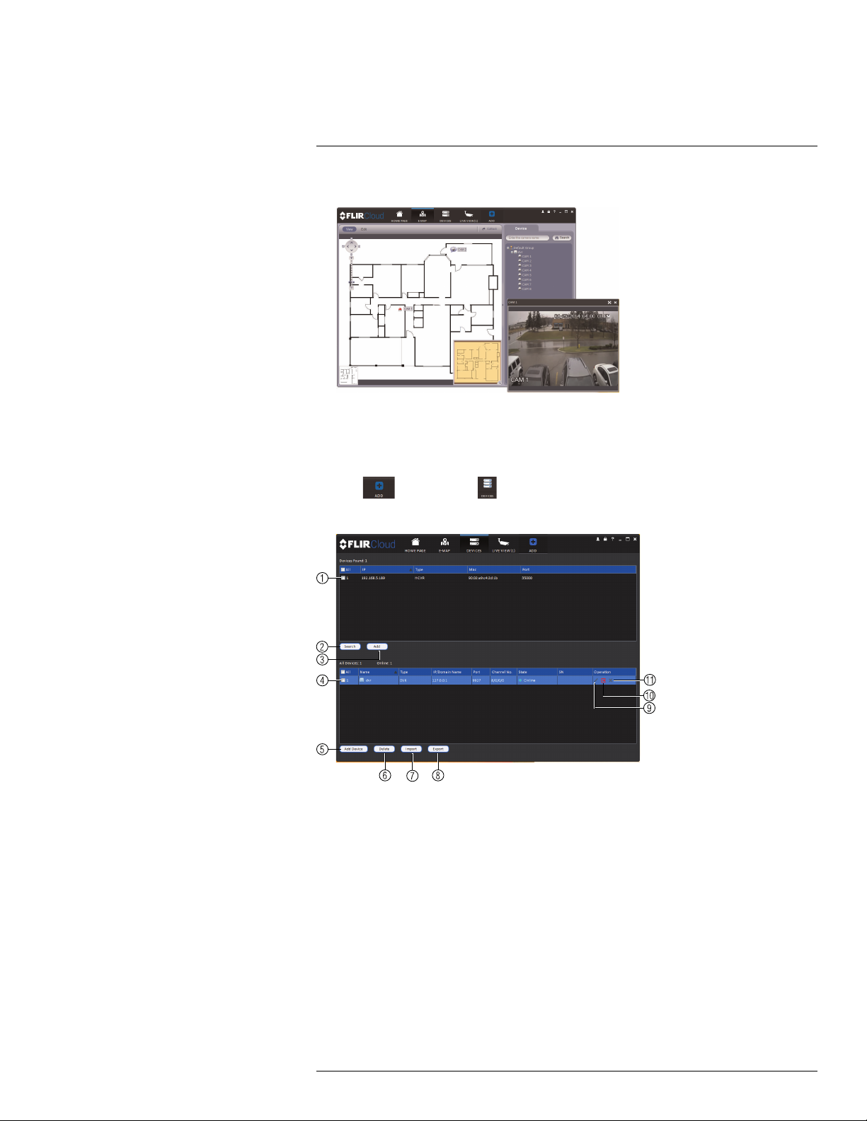
18
Using FLIR Cloud™ Client for PC or Mac
2. Double-click cameras on the map to open live video.
18.10 Devices
The Devices menu is where you can manage systems connected to the client software.
To access the Devices menu:
• Click
and then click .
Devices overview:
1. Devices Found: Shows systems that are connected to the same network as the computer where the client is installed. Once you connect to the system, it moves to the bottom of the screen.
2. Search: Refresh the list of systems connected to the network.
3. Add: Add checked systems to the client software.
4. Device list: Shows a list of systems connected to the client software, and shows which
systems are online.
5. Add Device: Add a remote system using a Device ID or IP/DDNS address.
6. Delete: Delete the selected system.
7. Import: Import a list of systems from a saved .xml file.
8. Export: Export a list of currently connected systems to an .xml file. This is useful if you
need to re-install the software or if you want to open the same list of systems on a different computer.
9. Delete: Delete system.
10. Manual connect/disconnect: Manually connect/disconnect the system.
#LX400028; r.27370/27370; en-US
90
 Loading...