

Page 1

M100 / M200 SERIES
INSTALLATION & OPERATION INSTRUCTIONS
English (en-US)
03-2017Date:
71001-2Document number:
© 2017 Raymarine UK Limited
Page 2

Page 3

T rademarkandpatentsnotice
Raymarine,T acktick,ClearPulse,T ruzoom,HSB,SeaT alk,SeaT alk
hs
,SeaTalk
ng
,Micronet,
Raytech,GearUp,MarineShield,Seahawk,Autohelm,Automagic,andVisionalityareregistered
orclaimedtrademarksofRaymarineBelgium.
FLIR,LightHouse,DownVision,SideVision,RealVision,Dragony,Quantum,Instalert,Infrared
Everywhere,TheWorld’sSixthSenseandClearCruiseareregisteredorclaimedtrademarks
ofFLIRSystems,Inc.
Allothertrademarks,tradenames,orcompanynamesreferencedhereinareusedforidentication
onlyandarethepropertyoftheirrespectiveowners.
Thisproductisprotectedbypatents,designpatents,patentspending,ordesignpatentspending.
Patentsnotice
ThisproductiscoveredbyoneormoreofUSPatentNos:7470904;7034301;6812465;7470902;
6929410andotherpatentspending,ordesignpatentspending.
FairUseStatement
Y oumayprintnomorethanthreecopiesofthismanualforyourownuse.Y oumaynotmakeany
furthercopiesordistributeorusethemanualinanyotherwayincludingwithoutlimitationexploiting
themanualcommerciallyorgivingorsellingcopiestothirdparties.
Exportcontrol
M100–SeriesandM200–SeriesthermalcamerasarecontrolledbyUSexportlaws.
Therearespecialversionsofthesystemthatareapprovedforinternationaldistributionandtravel.
PleasecontactFLIRcustomersupportifyouhaveanyquestions.
ContactdetailscanbefoundontheFLIRwebsite,www.ir.com.
ExportAdministrationRegulations(EAR)
ThisdocumentiscontrolledtoFLIRT echnologyLevel1.Theinformationcontainedinthisdocument
pertainstoadualuseproductcontrolledforexportbytheExportAdministrationRegulations(EAR).
FLIRtradesecretscontainedhereinaresubjecttodisclosurerestrictionsasamatteroflaw.Diversion
contrarytoUSlawisprohibited.USDepartmentofCommerceauthorizationisnotrequiredpriorto
exportortransfertoforeignpersonsorpartiesunlessotherwiseprohibited.
Softwareupdates
Important:ChecktheFLIRwebsiteforthelatestsoftwarereleasesforyourproduct.
www.ir.com/marine/support
Producthandbooks
ThelatestversionsofallEnglishandtranslatedhandbooksareavailabletodownloadinPDF
formatfromwww.ir.com/marine/support.
Pleasecheckthewebsitetoensureyouhavethelatesthandbooks.
Copyright©2017FLIRSystems,Inc.Allrightsreserved.
English(en-US)
Documentnumber:71001-2
Page 4

Page 5

Contents
Chapter1Importantinformation................................................................9
Cleaningthethermalcamera............................................................................10
Inspectingthethermalcamera..........................................................................11
Wateringress......................................................................................................11
Disclaimer............................................................................................................11
EMCinstallationguidelines................................................................................11
Suppressionferrites............................................................................................12
Connectionstootherequipment.......................................................................12
Declarationofconformity...................................................................................12
Productdisposal.................................................................................................12
Warrantyregistration...........................................................................................12
IMOandSOLAS................................................................................................13
T echnicalaccuracy.............................................................................................13
Chapter2Documentandproductinformation......................................15
2.1Documentinformation..................................................................................16
Applicableproducts.................................................................................................16
Systemkits..............................................................................................................16
Documentillustrations.............................................................................................17
Productdocumentation...........................................................................................17
2.2Productoverview.........................................................................................18
M100/M200..............................................................................................................18
Chapter3Planningtheinstallation.........................................................19
3.1Installationchecklist.....................................................................................20
Schematicdiagram..................................................................................................20
3.2Compatiblemultifunctiondisplays...............................................................21
Multifunctiondisplaysoftwarerequirements..........................................................21
3.3Partssupplied..............................................................................................22
Systemkits..............................................................................................................22
M100/M200–Seriescamera....................................................................................22
JCU–3......................................................................................................................25
3.4T oolsrequired..............................................................................................26
3.5T ypicalsystems............................................................................................27
3.6Warningsandcautions...............................................................................28
3.7Generallocationrequirements....................................................................29
Compasssafedistance..........................................................................................29
3.8Cameraorientation......................................................................................30
3.9Productdimensions.....................................................................................31
M100/M200Series..................................................................................................31
M100/M200Serieswithoptionaltop-downriser..................................................32
JCU-3.......................................................................................................................33
5
Page 6

Chapter4Cablesandconnections..........................................................35
4.1Generalcablingguidance...........................................................................36
Cabletypesandlength..........................................................................................36
Routingcables.........................................................................................................36
Strainrelief..............................................................................................................36
Circuitisolation........................................................................................................36
Cableshielding........................................................................................................37
4.2Connectionsoverview..................................................................................38
Connectingcables...................................................................................................38
4.3Powerconnection........................................................................................40
Powercableextension............................................................................................40
Powerdistribution....................................................................................................40
In-linefuseandthermalbreakerratings...............................................................42
Grounding—Dedicateddrainwire.......................................................................43
4.4Networkconnections...................................................................................44
Non-RayNetsystems...............................................................................................44
RayNetsystemswithLightHouse™-poweredRaymarinemultifunction
displays(MFDs)......................................................................................................46
Chapter5Mounting.....................................................................................51
5.1Cameramounting........................................................................................52
Locationrequirements.............................................................................................52
Mountingthecamera..............................................................................................52
Mountingthecamerawiththeoptionaltop-downriser(partnumber
A80509)....................................................................................................................54
5.2JCU–3Mounting..........................................................................................59
Locationrequirements.............................................................................................59
Removingthekeypadmat.....................................................................................59
Flushmountingthekeypad....................................................................................60
Surfacemountingthekeypad................................................................................61
Fittingthekeypadmat...........................................................................................61
Chapter6Systemoperationandsetup..................................................63
6.1Thermalcameraimage...............................................................................64
Thermalcamerastatusicons.................................................................................64
6.2Operationandfeaturesoverview...............................................................66
6.3Cameracontrol............................................................................................67
Pan,tiltandzoom..................................................................................................67
Thermalcamerahomeposition.............................................................................67
Thermalcamerasurveillancemode.......................................................................68
6.4Imageadjustments......................................................................................69
Thermalcamerascenepresets.............................................................................69
6
Page 7

Thermalcameracolormodes................................................................................69
Thermalcamerareversevideo..............................................................................69
6.5JCU–3controlsoverview............................................................................70
6.6Webbrowserinterface................................................................................72
Webbrowseruserinterfaceoverview...................................................................72
Settingupanetworkconnectiontothecamera.................................................72
LoggingintotheWebbrowseruserinterface....................................................73
LiveVideopage......................................................................................................74
Controlbuttons........................................................................................................76
ConguringJCU-3user-programmablebuttons(UPBs).......................................78
Chapter7Maintenance...............................................................................81
7.1Serviceandmaintenance...........................................................................82
7.2Cleaningthethermalcamera.....................................................................83
Chapter8Systemchecksandtroubleshooting....................................85
8.1Thermalcameratroubleshooting................................................................86
8.2FLIRMaritimeproductsupportandservicing..........................................87
Chapter9T echnicalspecication.............................................................89
9.1M100/M200Seriescameras.......................................................................90
T echnicalspecication............................................................................................90
9.2JCU-3...........................................................................................................91
T echnicalspecication............................................................................................91
Chapter10Sparesandaccessories........................................................93
10.1M100/M200Seriescameraaccessories..................................................94
10.2Keypadsparesandaccessories..............................................................95
10.3Networkhardware......................................................................................96
Networkcableconnectortypes.............................................................................97
10.4RayNettoRJ45adaptercables..............................................................98
10.5RayNettoRayNetcablesandconnectors..........................................100
7
Page 8

8
Page 9

Chapter1:Importantinformation
Warning:Productinstallationandoperation
•Thisproductmustbeinstalledandoperatedinaccordancewiththe
instructionsprovided.Failuretodosocouldresultinpersonalinjury ,
damagetoyourvesseland/orpoorproductperformance.
•Certiedinstallationbyanapprovedinstallerisrecommended.A
certiedinstallationqualiesforenhancedproductwarrantybenets.
Contactyourdealerforfurtherdetails,andrefertotheseparate
warrantydocumentpackedwithyourproduct.
Warning:Corrosion
T oavoidacceleratedgalvaniccorrosionoftheproduct,ensurethata
non-metallicisolationmountisusedwhenttingtheproductdirectlyto
largestainlesssteelplatforms/mounts,ordirectlytosteelconstruction
vessels.
Warning:Potentialignitionsource
ThisproductisNOTapprovedforuseinhazardous/ammable
atmospheres.DoNOTinstallinahazardous/ammableatmosphere
(suchasinanengineroomornearfueltanks).
Warning:Productgrounding
Beforeapplyingpowertothisproduct,ensureithasbeencorrectly
grounded,inaccordancewiththeinstructionsprovided.
Warning:Positivegroundsystems
Donotconnectthisunittoasystemwhichhaspositivegrounding.
Warning:Powersupplyvoltage
Connectingthisproducttoavoltagesupplygreaterthanthespecied
maximumratingmaycausepermanentdamagetotheunit.Referto
theT echnicalspecicationsectionforvoltagerating.
Warning:Switchoffpowersupply
Ensurethevessel’spowersupplyisswitchedOFFbeforestartingto
installthisproduct.DoNOTconnectordisconnectequipmentwiththe
powerswitchedon,unlessinstructedinthisdocument.
Warning:Entrapmenthazard
Thisproductfeaturesmovingpartsthatprovideapotentialentrapment
hazard.Keepclearofmovingpartsatalltimes.
Importantinformation
Warning:Ensuresafenavigation
Thisproductisintendedonlyasanaidtonavigationandmustnever
beusedinpreferencetosoundnavigationaljudgment.Onlyofcial
governmentchartsandnoticestomarinerscontainallthecurrent
informationneededforsafenavigation,andthecaptainisresponsible
fortheirprudentuse.Itistheuser’sresponsibilitytouseofcial
governmentcharts,noticestomariners,cautionandpropernavigational
skillwhenoperatingthisoranyotherFLIRproduct.
9
Page 10

Warning:Maintainapermanentwatch
Alwaysmaintainapermanentwatch,thiswillallowyoutorespondto
situationsastheydevelop.Failuretomaintainapermanentwatchputs
yourself,yourvesselandothersatseriousriskofharm.
Caution:Donotopentheunit
Theunitisfactorysealedtoprotectagainstatmospherichumidity ,
suspendedparticulatesandothercontaminates.Itisimportantthatyou
donotopentheunitorremovethecasingforanyreason.Opening
theunitwill:
•compromisethesealwithpossibledamagetotheunit,and
•voidthemanufacturer’swarranty.
Caution:Powersupplyprotection
Wheninstallingthisproductensurethepowersourceisadequately
protectedbymeansofasuitably-ratedfuseorautomaticcircuitbreaker.
Warning:Ensureallequipmenthasisolatedpower
supply
Thisproductfeaturesanisolatedpowersupply.Topreventpotential
damagetoequipment,itisrecommendedthatanyexternalequipment
connectedtothisproductalsofeaturesanisolatedpowersupply.
Caution:Serviceandmaintenance
Thisproductcontainsnouserserviceablecomponents.Pleaserefer
allmaintenanceandrepairtoauthorizedFLIRdealers.Unauthorized
repairmayaffectyourwarranty.
Caution:Suncovers
•Ifyourproductissuppliedwithasuncover,toprotectagainstthe
damagingeffectsofultraviolet(UV)light,alwaystthesuncover
whentheproductisnotinuse.
•Suncoversmustberemovedwhentravellingathighspeed,whether
inwaterorwhenthevesselisbeingtowed.
Cleaningthethermalcamera
Thecamerahousingandlenswillrequireoccasionalcleaning.Youshouldcleanthe
lenswhenimagequalitydegradationisnoticedorexcessivecontaminantbuildupis
seen.Cleantheinterfacebetweentheyokeandbaseoftentopreventaccumulationof
debrisorsaltdeposits.
Whencleaningthisproduct:
•DoNOTwipethelenswindowwithadrycloth,orwithabrasivematerialssuchas
paperorscrubbrushes,asthiscouldscratchthecoating.
•DoNOTuseacidorammoniabasedproducts.
•DoNOTpressurewash.
Particularcareshouldbetakenwhencleaningthelenswindow,thishasaprotective
anti-reectivecoatingwhichmaybedamagedbyimpropercleaning.
1.Switchoffthepowertotheunit.
2.Cleanthecamerabodywithaclean,softcottoncloth.Youcanmoistenthecloth
anduseamilddetergentifrequired.
10
Page 11

3.Cleanthecameralens.
•Rinsethelenswithfreshwatertoremovealldirtparticlesandsaltdeposits,and
allowtodrynaturally.
•Ifanyspotsorsmearsremain,verygentlywipethelenswindowwithaclean
microbreclothorsoftcottoncloth.
•Ifnecessary,useisopropylalcohol(IPA)oramilddetergenttoremoveany
remainingspotsormarks.
Inspectingthethermalcamera
Routinelyinspectthecameraanditsmountingsurfacetoensurethatitisinstalled
securely,thatthecoatedsurfacesareintact,andthattherearenosignsofcorrosion.
Whenthecameraispoweredoff,graspitrmlyatthebaseandconrmitisrigidand
secure.Thenholdthecameraabovethebaseandconrmitwillrotatefreelyand
withoutnoticeablewobbleorloosenessaroundthepanbearing.
Wateringress
Wateringressdisclaimer
AlthoughthewaterproofratingcapacityofthisproductmeetsthestatedIPXstandard
(refertotheproduct’sT echnicalSpecication),waterintrusionandsubsequentequipment
failuremayoccuriftheproductissubjectedtocommercialhigh-pressurewashing.FLIR
willnotwarrantproductssubjectedtohigh-pressurewashing.
Disclaimer
FLIRdoesnotwarrantthatthisproductiserror-freeorthatitiscompatiblewith
productsmanufacturedbyanypersonorentityotherthanFLIR.
FLIRisnotresponsiblefordamagesorinjuriescausedbyyouruseorinabilitytouse
theproduct,bytheinteractionoftheproductwithproductsmanufacturedbyothers,or
byerrorsininformationutilizedbytheproductsuppliedbythirdparties.
EMCinstallationguidelines
FLIRequipmentandaccessoriesconformtotheappropriateElectromagneticCompatibility
(EMC)regulations,tominimizeelectromagneticinterferencebetweenequipmentand
minimizetheeffectsuchinterferencecouldhaveontheperformanceofyoursystem
CorrectinstallationisrequiredtoensurethatEMCperformanceisnotcompromised.
Note:InareasofextremeEMCinterference,someslightinterferencemaybenoticed
ontheproduct.Wherethisoccurstheproductandthesourceoftheinterference
shouldbeseparatedbyagreaterdistance.
ForoptimumEMCperformancewerecommendthatwhereverpossible:
•FLIRequipmentandcablesconnectedtoitare:
–Atleast1m(3ft)fromanyequipmenttransmittingorcablescarryingradiosignals
e.g.VHFradios,cablesandantennas.InthecaseofSSBradios,thedistance
shouldbeincreasedto7ft(2m).
–Morethan2m(7ft)fromthepathofaradarbeam.Aradarbeamcannormally
beassumedtospread20degreesaboveandbelowtheradiatingelement.
•Theproductissuppliedfromaseparatebatteryfromthatusedforenginestart.This
isimportanttopreventerraticbehavioranddatalosswhichcanoccuriftheengine
startdoesnothaveaseparatebattery.
•FLIRspeciedcablesareused.
•Cablesarenotcutorextended,unlessdoingsoisdetailedintheinstallationmanual.
Importantinformation
11
Page 12

Note:Whereconstraintsontheinstallationpreventanyoftheabove
recommendations,alwaysensurethemaximumpossibleseparationbetweendifferent
itemsofelectricalequipment,toprovidethebestconditionsforEMCperformance
throughouttheinstallation
Suppressionferrites
•Cablesmaybepre-ttedorsuppliedwithsuppressionferrites.Theseareimportant
forcorrectEMCperformance.Ifferritesaresuppliedseparatelytothecables(i.e.
notpre-tted),youmusttthesuppliedferrites,usingthesuppliedinstructions.
•Ifaferritehastoberemovedforanypurpose(e.g.installationormaintenance),it
mustbereplacedintheoriginalpositionbeforetheproductisused.
•Useonlyferritesofthecorrecttype,suppliedbythemanufactureroritsauthorized
dealers.
•Whereaninstallationrequiresmultipleferritestobeaddedtoacable,additional
cableclipsshouldbeusedtopreventstressontheconnectorsduetotheextra
weightofthecable.
•Ifyourcamerainstallationrequireslongcableruns,youmayneedtotadditional
ferritestomaintainacceptableEMCperformance.
Connectionstootherequipment
Requirementforferritesonnon-FLIRcables
IfyourFLIRequipmentistobeconnectedtootherequipmentusingacablenot
suppliedbyFLIR,asuppressionferriteMUSTalwaysbeattachedtothecablenear
theFLIRunit.
Declarationofconformity
FLIRSystemsInc.declaresthatthisproductiscompliantwiththeessentialrequirements
ofEMCdirective2004/108/EC.
TheoriginalDeclarationofConformitycerticatemaybeviewedontherelevantproduct
pageatwww.ir.com.
Productdisposal
DisposeofthisproductinaccordancewiththeWEEEDirective.
TheWasteElectricalandElectronicEquipment(WEEE)Directiverequiresthe
recyclingofwasteelectricalandelectronicequipment.
Warrantyregistration
T oregisteryourFLIRproductownership,pleasevisitwww.ir.comandregisteronline.
Itisimportantthatyouregisteryourproducttoreceivefullwarrantybenets.Y ourunit
packageincludesabarcodelabelindicatingtheserialnumberoftheunit.Y ouwill
needthisserialnumberwhenregisteringyourproductonline.Y oushouldretainthe
labelforfuturereference.
12
Page 13

IMOandSOLAS
Theequipmentdescribedwithinthisdocumentisintendedforuseonleisuremarine
boatsandworkboatsNOTcoveredbyInternationalMaritimeOrganization(IMO)and
SafetyofLifeatSea(SOLAS)CarriageRegulations.
T echnicalaccuracy
T othebestofourknowledge,theinformationinthisdocumentwascorrectatthe
timeitwasproduced.However,FLIRcannotacceptliabilityforanyinaccuraciesor
omissionsitmaycontain.Inaddition,ourpolicyofcontinuousproductimprovement
maychangespecicationswithoutnotice.Asaresult,FLIRcannotacceptliability
foranydifferencesbetweentheproductandthisdocument.PleasechecktheFLIR
website(www.ir.com/marine/support)toensureyouhavethemostup-to-dateversion(s)
ofthedocumentationforyourproduct.
Importantinformation
13
Page 14

14
Page 15

Chapter2:Documentandproductinformation
Chaptercontents
•2.1Documentinformationonpage16
•2.2Productoverviewonpage18
Documentandproductinformation
15
Page 16
2.1Documentinformation
Thisdocumentcontainsimportantinformationrelatedtotheinstallationandoperationof
yourFLIRproduct.
Thedocumentincludesinformationtohelpyou:
•planyourinstallationandensureyouhaveallthenecessaryequipment;
•installandconnectyourproductaspartofawidersystemofconnectedmarine
electronics;
•useyourproductalongwithanappropriatevideomonitor,joystickcontrolunit(JCU),
webbrowser,ormultifunctiondisplay(MFD).
•troubleshootproblemsandobtaintechnicalsupportifrequired.
ThisandotherFLIRproductdocumentsareavailabletodownloadinPDFformat
fromwww.ir.com/marine/support.
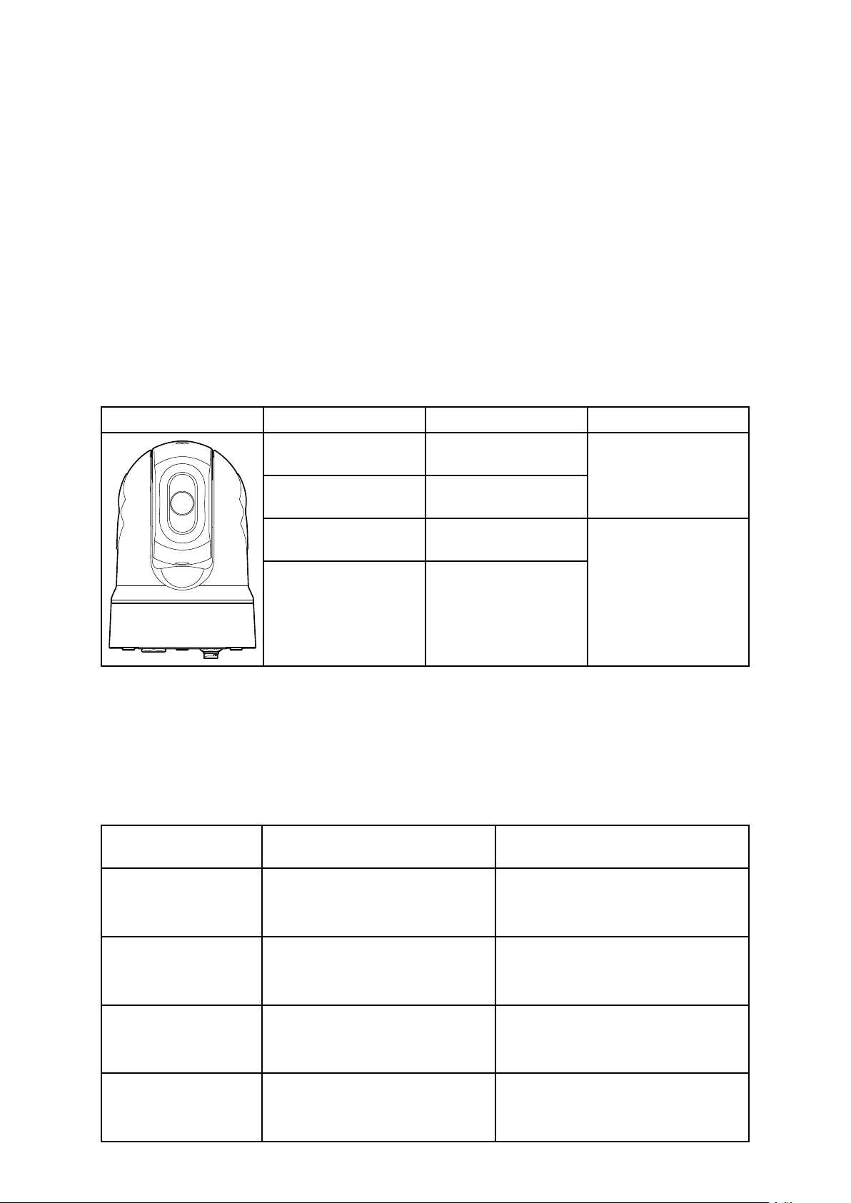
Applicableproducts
Thisdocumentisapplicabletothefollowingproducts:
PartnumberNameDescription
E70432M132
(9Hz)
E70431M132
(30Hz)
E70354M232
(9Hz)
E70353M232
(30Hz)
Thermaltilt-only,
night-visionIPvideo
camera
Thermalpan-and-tilt,
night-visionIPvideo
camera
Systemkits
M100/M200–Seriesthermalcamerasaresuppliedindividually ,oraspartofasystemkit.
Inadditiontothethermalcamera,systemkitsincludeajoystickcontrolunit(JCU)for
controllingthecamera.
Thecontentofeachsystemkitislistedbelow.Foralistoftheindividualpartssupplied
witheachcamera,seeM100/M200–Seriescamera.
Systemkit
partnumberDescription
Contents
(partnumbers)
T70333
T70334
T70335
T70336
16
M132CameraSystemKit
30Hz
M132CameraSystemKit
9Hz
M232CameraSystemKit
30Hz
M232CameraSystemKit
9Hz
•E70431:M132thermalcamera
30Hz(tiltonly)
•A80510:JCU-3controlunit
•E70432:M132thermalcamera
9Hz(tiltonly)
•A80510:JCU-3controlunit
•E70353:M232thermalcamera
30Hz(pan&tilt)
•A80510:JCU-3controlunit
•E70354:M232thermalcamera
9Hz(pan&tilt)
•A80510:JCU-3controlunit
Page 17

Note:Ifyouwanttoviewtheimagefromyourcameraonamonitor,thecamera’s
digitalIP-videooutputmustbeconvertedtoanalogcomponent-videousingadecoder
unit.Suitablevideodecoderunitsareavailableseparately .
Documentillustrations
Y ourproductmaydifferslightlyfromthatshownintheillustrationsinthisdocument,
dependingonproductvariantanddateofmanufacture.
Allimagesareprovidedforillustrationpurposesonly.
Productdocumentation
Thefollowingdocumentationisapplicabletoyourproduct:
DescriptionPartnumber
M100/M200ThermalCameraInstallationandOperation
Instructions
InstallationandoperationofanM100–SeriesorM200–Series
thermalcameraandconnectiontoawidersystemofmarine
electronics.
M100/M200–Seriessurfacemountingtemplate
MountingdiagramformountinganM100–SeriesorM200–Series
thermalcamera.
M100/M200–Seriestop-downrisermountingtemplate
Mountingdiagramformountingthetop-downriserforan
M100–SeriesorM200–Seriesthermalcamera.
M100/M200ThermalCameraVisualQuickStartGuide
Single-pageillustratedguidetohelpyougetup-and-running
withyourthermalcamera.
LightHouse™2MFDOperationInstructions
DetailstheoperationoftheCameraapplicationforLightHouse™
2-compatiblemultifunctiondisplays.
LightHouse™3MFDAdvancedoperationInstructions
DetailstheoperationoftheCameraapplicationforLightHouse™
3-compatiblemultifunctiondisplays.
71001
77001
77003
76001
81360
81370
Documentandproductinformation
17
Page 18
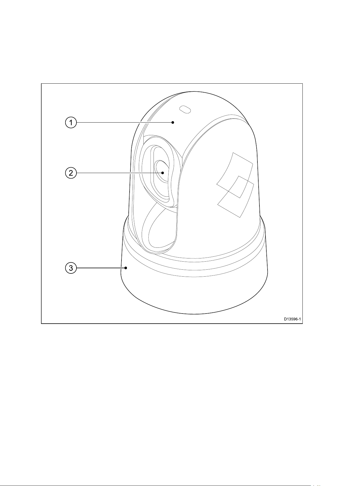
2.2Productoverview
M100/M200
TheM100/M200–Seriesisamaritimethermalimagingsystemforuseonnearlyany
kindofvessel.Itprovidesaclearimageinlow-lightandno-lightconditions.For
example,athermalcameracanhelpyounavigateatnightoridentifyobstaclesinareas
oflowvisibilityoreventotaldarkness.
1.Tiltassembly .
2.Thermalcameralenswindow.
3.Panassembly(xedpositionforM100–Series).
TheM100/M200–Seriessystemhasthefollowingkeyfunctionsandfeatures:
•IPconnectivitytosimplifyinstallationandsystemintegration.
•H264–encodedIPvideostream.
•Panandtiltoperations(tiltonlyforM100–Series)withdedicatedjoystickcontrolunit,
multifunctiondisplay(MFD),orwebbrowser.
•Automaticcameraadjustmenttosuitchangingconditions.
•Presetmodes(Scenes)optimizedforprevailingconditions.
•ClearCruise™intelligentthermalanalyticstechnology;providesaudibleandvisual
alertswhen“non-water”objectsareidentiedinthescene.(RequiresaRaymarine®
MFDrunningLightHouse™3software.)
•Automaticwindowheaterstode-icethelenswindowincoldweather.
•12Vor24Vdcpower.
18
Page 19

Chapter3:Planningtheinstallation
Chaptercontents
•3.1Installationchecklistonpage20
•3.2Compatiblemultifunctiondisplaysonpage21
•3.3Partssuppliedonpage22
•3.4T oolsrequiredonpage26
•3.5T ypicalsystemsonpage27
•3.6Warningsandcautionsonpage28
•3.7Generallocationrequirementsonpage29
•3.8Cameraorientationonpage30
•3.9Productdimensionsonpage31
Planningtheinstallation
19
Page 20

3.1Installationchecklist
Installationincludesthefollowingactivities:
InstallationT ask
1
2
3
4
5
6
7
8
Planyoursystem.
Obtainallrequiredequipmentandtools.
Siteallequipment.
Routeallcables.
Drillcableandmountingholes.
Makeallconnectionsintoequipment.
Secureallequipmentinplace.
Poweronandtestthesystem.
Schematicdiagram
Aschematicdiagramisanessentialpartofplanninganyinstallation.Itisalsouseful
foranyfutureadditionsormaintenanceofthesystem.Thediagramshouldinclude:
•Locationofallcomponents.
•Connectors,cabletypes,routesandlengths.
20
Page 21

3.2Compatiblemultifunctiondisplays
Note:ARaymarine®LightHouse™-compatiblemultifunctiondisplay(MFD)isnot
requiredtouseaM100/M200-Seriescamera.Howevercertaincamerafeaturesmay
notbeaccessiblewithoutone.
ThisproductiscompatiblewiththefollowingRaymarine®LightHouse™multifunction
displays.
•aSeries,cSeries,eSeries,eSSeries.
•gSSeries.
•Axiom.
Multifunctiondisplaysoftwarerequirements
T ousethisproductwithaRaymarine®LightHouse™-compatiblemultifunctiondisplay
(MFD),ensurethatyourMFDisrunningthelatestversionoftheLightHouse™2or
LightHouse™3software.
Note:
•ThisproductisNOTcompatiblewithLightHouse™2softwareversions17orearlier.
•ThelatestLightHouse™MFDsoftwarecanbeobtainedbyvisiting
www.raymarine.com/software.
Planningtheinstallation
21
Page 22

3.3Partssupplied
Systemkits
M100/M200–Seriesthermalcamerasaresuppliedindividually ,oraspartofasystemkit.
Inadditiontothethermalcamera,systemkitsincludeajoystickcontrolunit(JCU)for
controllingthecamera.
Thecontentofeachsystemkitislistedbelow.Foralistoftheindividualpartssupplied
witheachcamera,seeM100/M200–Seriescamera.
Systemkit
partnumberDescription
T70333
T70334
T70335
T70336
Note:Ifyouwanttoviewtheimagefromyourcameraonamonitor,thecamera’s
digitalIP-videooutputmustbeconvertedtoanalogcomponent-videousingadecoder
unit.Suitablevideodecoderunitsareavailableseparately .
M132CameraSystemKit
30Hz
M132CameraSystemKit
9Hz
M232CameraSystemKit
30Hz
M232CameraSystemKit
9Hz
Contents
(partnumbers)
•E70431:M132thermalcamera
30Hz(tiltonly)
•A80510:JCU-3controlunit
•E70432:M132thermalcamera
9Hz(tiltonly)
•A80510:JCU-3controlunit
•E70353:M232thermalcamera
30Hz(pan&tilt)
•A80510:JCU-3controlunit
•E70354:M232thermalcamera
9Hz(pan&tilt)
•A80510:JCU-3controlunit
M100/M200–Seriescamera
Thefollowingitemsaresuppliedwithyourproduct.
22
Page 23
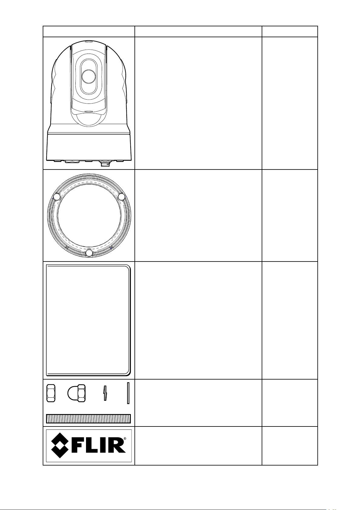
ItemDescriptionQuantity
Thermalcamera
Thermalcamerabase-seal
1
1
Documentationpack
Thermalcamerafasteners:nuts,dome
nuts,springwashers,atwashers,and
threadedstuds
Self-adhesivedecals(forball-down
mountingonly)
1
3ofeach
2
Planningtheinstallation
23
Page 24

ItemDescriptionQuantity
T op-downriserkit(includesriser,riser
1
baseseal,andrisermountingtemplate)
*Right-angledRayNet-to-RayNetcable
1
(10m)
RayNet-to-RJ45adaptercable(100
1
mm)
*Right-angled3-pinpowercable(10m)
1
*Thesuppliedright-angledRayNetandPowercablesaresuitableformountingon
surfacesupto25.4mm(1.0inch)thick.Whenmountingonthickersurfaces,youmay
needtouseRayNetandPowercableswithstraightconnectors(availableseparately).
Note:Forfurtherdetailsonnetworkhardwareandcables,seeChapter10Spares
andaccessories.
24
Page 25
JCU–3
TheJCU-3joystickcontrolunitisincludedincamerasystempacks,andisalso
availabletopurchaseasaseparateaccessory.Theunitissuppliedwithbotha
portrait-orientedkeypad(tted),andalandscape-orientedkeypad.
Forinformationonotheraccessories,seeChapter10Sparesandaccessories.
Note:YourM100/M200-Seriesthermalcameraisalsocompatiblewiththefollowing
joystickcontrolunits,providedwithotherFLIRandRaymarinecamerasystems:
•JCU-1(partno.500-0385-00)—joystickcontrolunitforFLIRM-Seriesand
RaymarineT-Seriescameras
•JCU-2(partno.500-0398-00)—joystickcontrolunitforFLIRM400-Series,
MV-SeriesandMU-Seriescameras
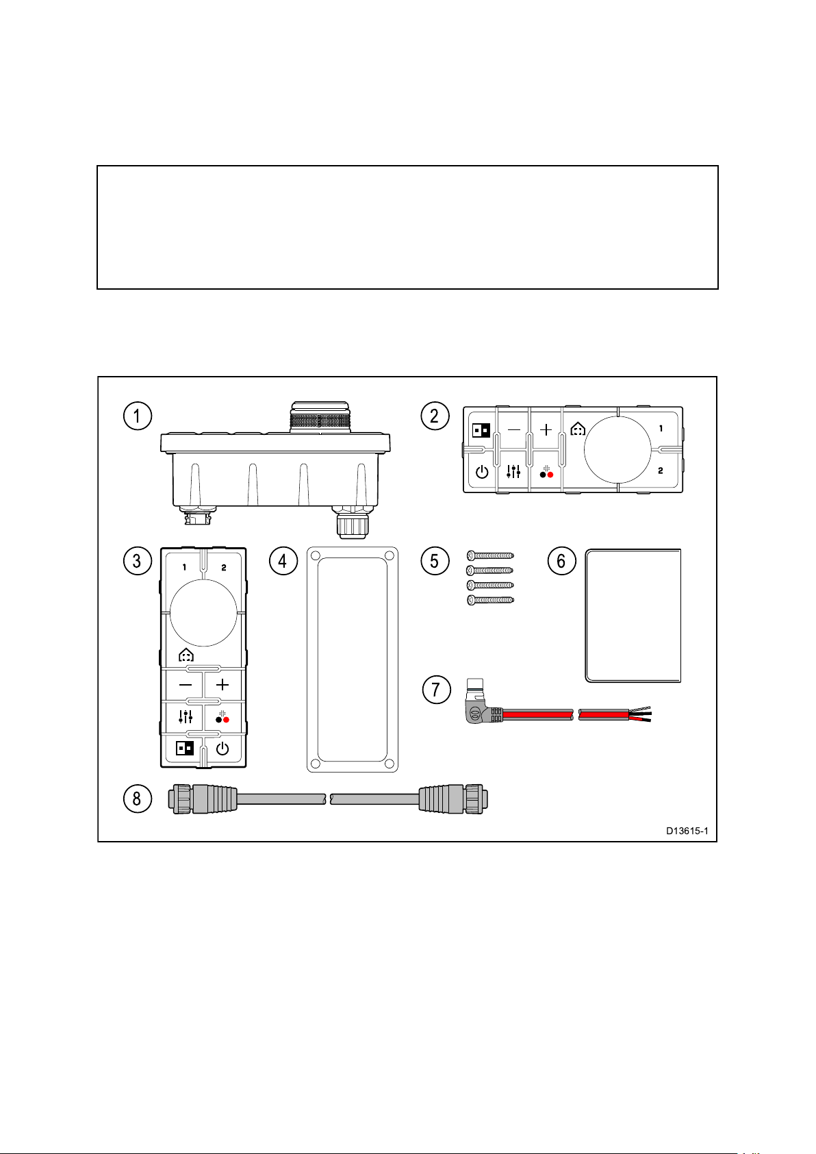
Partssupplied
Thepartssuppliedwiththekeypadareshownbelow.
1.JCU-3keypad
2.Landscapekeypadmat
3.Portraitkeypadmat(suppliedttedtotheunit)
4.Mountinggasket
5.4xmountingxings
6.Documentationpack
7.Rightangledpowercable2m(6.6ft.)
8.RayNetnetworkcable2m(6.6ft.)
Planningtheinstallation
25
Page 26
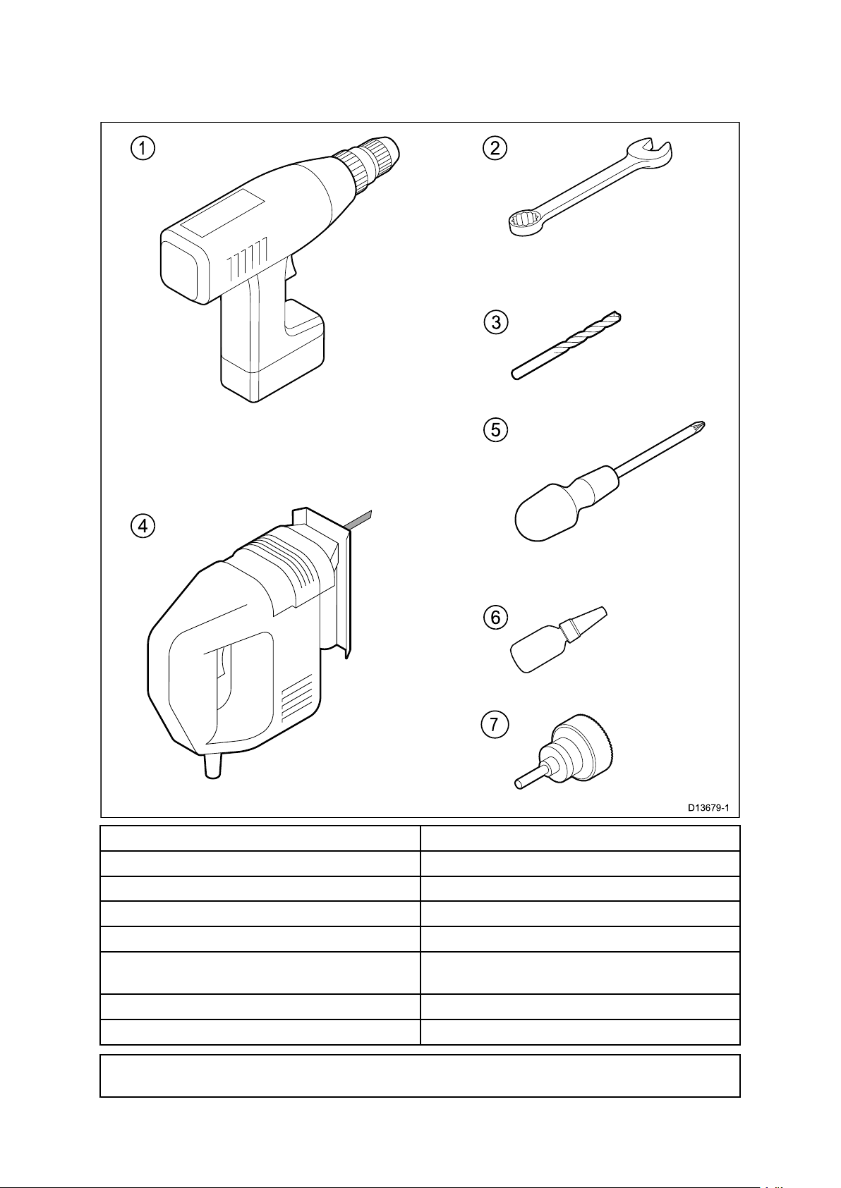
3.4T oolsrequired
Thefollowingtoolsarerequiredforinstallation.
ItemDescription
1.
2.10mmspanner
3.
4.
5.
6.
7.
Note:*Theappropriatedrillbitsizeisdependentonthethicknessandmaterial
ofthemountingsurface.
26
Drill
Drillbitofappropriatesize*
Jigsaw(onlyrequiredforJCUinstallation)
Pozi-drivescrewdriver(onlyrequiredfor
JCUinstallation)
Thread-lock
50mm(2inch)Holesaw
Page 27

3.5T ypicalsystems
Note:Forinformationonhowtoconnecttheproduct,refertotheChapter4Cables
andconnectionssection.Forinformationonavailablecablesandaccessories,refer
totheChapter10Sparesandaccessoriessection.
•BasicWebbrowsersystem:Y oucanconnecttheproductdirectlytoanIP-capable
device,suchasalaptoporPC,usingthesuppliedRayNetcableandRayNet-to-RJ45
adaptercable.Y oucancontrolthecamerathroughtheuserinterfacepresentedon
thewebbrowser.
•BasicvideodisplaysystemwithJCU:Y oucanconnecttheproductdirectlyto
aprimaryanalogvideodisplayviaanEthernetswitch(usingthesuppliedRayNet
cableandRayNet-to-RJ45adaptercable),IPvideodecoder(availableseparately),
andacoaxialvideocable.Y oucancontrolthecamerawithaJCU-3unit,also
connectedtotheEthernetswitch.
•BasicWebbrowsersystemwithJCU:Y oucanconnecttheproducttoan
IP-capabledevice,suchasalaptoporPC,viaanEthernetswitch(usingthesupplied
RayNetcableandRayNet-to-RJ45adaptercable),andanadditionalEthernetcable.
Y oucancontrolthecamerathroughtheuserinterfacepresentedonthewebbrowser,
orwithaJCU-3unit,alsoconnectedtotheEthernetswitch.
•BasicLightHouse™-poweredRaymarinemultifunctiondisplay(MFD)system:Y ou
canconnecttheproductdirectlytoaRaymarineMFDusingthesuppliedRayNet
cable.Y oucancontrolthecameradirectlyusingtheMFD.Foramoreexiblesystem,
youcaninstallaRayNetswitchbetweenthecameraandtheMFD,andaddaJCU-3
unit(alsoconnectedtotheRayNetswitch)toprovideadditionalcameracontrols.
•Complexsystemwithmultiplecameras,MFDs,andJCUs:WithsufcientRayNet
orEthernetportsavailableoninstalledswitches,andappropriateRayNetandEthernet
cables,youcanconnectmultiplecameras,MFDs,andJCUstogethertoforman
integratedsystem.Y oucanuseanyJCUorMFDtocontrolandmonitoranycamera.
Planningtheinstallation
27
Page 28

3.6Warningsandcautions
Important:Beforeproceeding,ensurethatyouhavereadandunderstoodthe
warningsandcautionsprovidedintheChapter1Importantinformationsection
ofthisdocument.
28
Page 29

3.7Generallocationrequirements
Importantconsiderationswhenchoosingasuitablelocationforyourproduct.
Thisproductissuitableformountingbelowdecks.
Theproductshouldbemountedwhereitwillbe:
•protectedfromphysicaldamageandexcessivevibration.
•wellventilatedandawayfromheatsources.
Whenchoosingalocationfortheproduct,considerthefollowingpointstoensure
reliableandtrouble-freeoperation:
•Access—theremustbesufcientspacetoenablecableconnectionstotheproduct,
avoidingtightbendsinthecable.
•Diagnostics—theproductmustbemountedinalocationwherethediagnostics
LEDiseasilyvisible.
Note:NotallproductsincludeadiagnosticsLED.RefertotheChapter8System
checksandtroubleshootingformoreinformation.
•Electricalinterference—theproductshouldbemountedfarenoughawayfrom
anyequipmentthatmaycauseinterferencesuchasmotors,generatorsandradio
transmitters/receivers.
•Magneticcompass—refertotheCompasssafedistancesectioninthisdocument
foradviceonmaintainingasuitabledistancebetweenthisproductandany
compassesonyourvessel.
•Power—tokeepcablerunstoaminimum,theproductmustbelocatedasclose
aspossibletothevessel’sdcpowersupply.
•Mountingsurface—ensuretheproductisadequatelysupportedonasecure
surface.RefertotheweightinformationprovidedintheT echnicalspecicationforthis
productandensurethattheintendedmountingsurfaceissuitableforbearingthe
productweight.DoNOTmountunitsorcutholesinplaceswhichmaydamagethe
structureofthevessel.
Compasssafedistance
T opreventpotentialinterferencewiththevessel'smagneticcompasses,ensurean
adequatedistanceismaintainedfromtheproduct.
Whenchoosingasuitablelocationfortheproductyoushouldaimtomaintainthe
maximumpossibledistancefromanycompasses.T ypicallythisdistanceshouldbeat
least1m(3ft)inalldirections.Howeverforsomesmallervesselsitmaynotbe
possibletolocatetheproductthisfarawayfromacompass.Inthissituation,when
choosingtheinstallationlocationforyourproduct,ensurethatthecompassisnot
affectedbytheproductwhenitisinapoweredstate.
Planningtheinstallation
29
Page 30
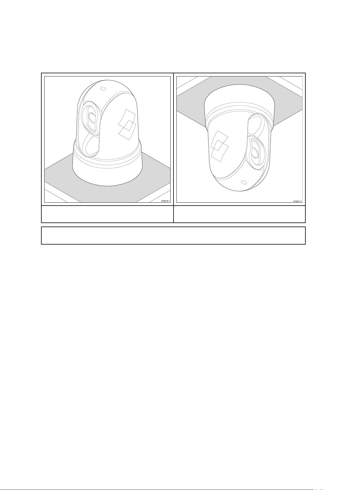
3.8Cameraorientation
Thecameracanbemountedin2orientationsinformallyknownas“Ballup”and
“Balldown”.
Thedefaultimageorientationisfortheball-upconguration;ifthecameraistobe
mountedintheball-downcongurationthenthevideoimagemustbeipped.
Ball-up:Thecameraismountedontop
ofthemountingsurface.
Note:Forball-downmountingyoumustsettheball-downoptioninthecamera
systemsetupmenuappropriately .
Ball-down:Thecameraissuspended
upsidedown,belowthemountingsurface.
30
Page 31

3.9Productdimensions
M100/M200Series
Planningtheinstallation
31
Page 32

M100/M200Serieswithoptionaltop-downriser
Note:Basediameterwithriserbase-sealttedis190mm(7.48in).
32
Page 33

JCU-3
Productdimensions
DimensionMeasurement
A
B
C
D
E
F
G
H
I
J
34.8mm(1.37in)
10.5mm(0.41in)
28.4mm(1.12in.)
31.7mm(1.25in.)
50.7mm(2.00in.)
80.0mm(3.15in.)
119.0mm(4.69in.)
133.0mm(5.24in.)
41.0mm(1.61in.)
55.0mm(2.17in.)
Planningtheinstallation
33
Page 34

34
Page 35

Chapter4:Cablesandconnections
Chaptercontents
•4.1Generalcablingguidanceonpage36
•4.2Connectionsoverviewonpage38
•4.3Powerconnectiononpage40
•4.4Networkconnectionsonpage44
Cablesandconnections35
Page 36

4.1Generalcablingguidance
Cabletypesandlength
Itisimportanttousecablesoftheappropriatetypeandlength
•Unlessotherwisestateduseonlystandardcablesofthecorrecttype,suppliedby
FLIR.
•Ensurethatanynon-FLIRcablesareofthecorrectqualityandgauge.Forexample,
longerpowercablerunsmayrequirelargerwiregaugestominimizevoltagedrop
alongtherun.
Routingcables
Cablesmustberoutedcorrectly,tomaximizeperformanceandprolongcablelife.
•DoNOTbendcablesexcessively.Whereverpossible,ensureaminimumbend
diameterof200mm(8in)/minimumbendradiusof100mm(4in).
•Protectallcablesfromphysicaldamageandexposuretoheat.Usetrunkingor
conduitwherepossible.DoNOTruncablesthroughbilgesordoorways,orcloseto
movingorhotobjects.
•Securecablesinplaceusingtie-wrapsorlacingtwine.Coilanyextracableandtie
itoutoftheway.
•Whereacablepassesthroughanexposedbulkheadordeckhead,useasuitable
watertightfeed-through.
•DoNOTruncablesneartoenginesoruorescentlights.
Alwaysroutedatacablesasfarawayaspossiblefrom:
•otherequipmentandcables,
•highcurrentcarryingACandDCpowerlines,
•antennae.
Strainrelief
Ensureadequatestrainreliefisprovided.Protectconnectorsfromstrainandensure
theywillnotpulloutunderextremeseaconditions.
Circuitisolation
AppropriatecircuitisolationisrequiredforinstallationsusingbothACandDCcurrent:
•Alwaysuseisolatingtransformersoraseparatepower-invertertorunPC’s,processors,
displaysandothersensitiveelectronicinstrumentsordevices.
•AlwaysuseanisolatingtransformerwithWeatherF AXaudiocables.
•Alwaysuseanisolatedpowersupplywhenusinga3rdpartyaudioamplier.
•AlwaysuseanRS232/NMEAconverterwithopticalisolationonthesignallines.
•AlwaysmakesurethatPC’sorothersensitiveelectronicdeviceshaveadedicated
powercircuit.
36
Page 37

Cableshielding
Ensurethatalldatacablesareproperlyshieldedthatthecableshieldingisintact(e.g.
hasn’tbeenscrapedoffbybeingsqueezedthroughatightarea).
Cablesandconnections37
Page 38

4.2Connectionsoverview
1.Poweranddrain
2.RayNetconnectionto:
a.RayNetconnectoronRaymarinenetworkswitchorLightHouse™-powered
Raymarinemultifunctiondisplay(usingRayNet-to-RayNetcable),OR
b.RJ45connectoronthird-partynetworkswitch,PC/laptopcomputer,orIPvideo
decoder(availableseparately),usingthesuppliedRayNet-to-RJ45adaptercable.
Note:Thesuppliedright-angledRayNetandPowercablesaresuitableformountingon
surfacesupto25.4mm(1.0inch)thick.Whenmountingonthickersurfaces,youmay
needtouseRayNetandPowercableswithstraightconnectors(availableseparately).
Note:Thecablesshouldberoutedtoadryareaofthevesselforconnection.
Alternativelyyoumustensurethatallconnectionsarewatertight.
Note:Ifyouwanttomakecableconnectionstothecamerabeforemountingitto
yourvessel(forexample,totestthecamera),rstattachthethreethreadedstudsto
thebase(seeMountingthecamera).Thiswillhelptoprotectthecableconnectors
onthebaseofthecamera,andalsoprovidesastableplatform,helpingtoprevent
damagecausedbytheunitrollingofftheedgeoftheworksurface.
Connectingcables
Followthestepsbelowtoconnectthecable(s)toyourproduct.
1.Ensurethatthevessel'spowersupplyisswitchedoff.
2.Ensurethatthedevicebeingconnectedhasbeeninstalledinaccordancewiththe
installationinstructionssuppliedwiththatdevice.
3.Ensuringcorrectorientation,pushcableconnectorsfullyontothecorresponding
connectors.
4.Ifapplicable,engageanylockingmechanismtoensureasecureconnection.
38
Page 39

5.Ensureanybareendedwireconnectionsaresuitablyinsulatedtopreventcorrosion
duetowateringress.
Cablesandconnections39
Page 40

4.3Powerconnection
Powermustbesuppliedtothecamerafromanappropriatepowersource.
Powerconnectionrequirements
•12or24Vdcnominalsupplyvoltage
•Isolatedpowersupply
•Connectedviaanappropriatelyratedthermalbreakerorfusedswitch.
Powerconnectioncolors
ItemColorDescription
1
2
3
Red
Powerin+ve(12/24V)
Black(thick)Powerin-ve(0V)
Black(thin)
Drain/Ground
Powercableextension
Theproductissuppliedwithapowercable,whichcanbeextendedifrequired.
•Thepowercableforeachunitinyoursystemshouldberunasaseparate,single
lengthof2-wirecablefromtheunittothevessel'sbatteryordistributionpanel.
•Forpowercableextensions,itisrecommendedthataminimumwiregaugeof16
AWG(1.31mm
athickerwiregauge(e.g.14AWG(2.08mm
•Animportantrequirementforalllengthsofpowercable(includinganyextension)isto
ensurethatthereisacontinuousminimumvoltageof10.8Vattheproduct’spower
connector,withafullyatbatteryat11V .
Important:Beawarethatsomeproductsinyoursystem(suchassonarmodules)
cancreatevoltagepeaksatcertaintimes,whichmayimpactthevoltageavailableto
otherproductsduringthepeaks.
2
).Forcablerunslongerthan15meters,youmayneedtoconsider
2
),or12AWG(3.31mm
2
)).
Powerdistribution
Recommendationsandbestpractice.
•Theproductissuppliedwithapowercable.Onlyusethepowercablesupplied
withtheproduct.DoNOTuseapowercabledesignedfor,orsuppliedwith,
adifferentproduct.
•RefertothePowerconnectionsectionformoreinformationonhowtoidentifythe
wiresinyourproduct’spowercable,andwheretoconnectthem.
•Seebelowformoreinformationonimplementationforsomecommonpower
distributionscenarios.
40
Page 41

Important:Whenplanningandwiring,takeintoconsiderationotherproductsin
yoursystem,someofwhich(e.g.sonarmodules)mayplacelargepowerdemand
peaksonthevessel’selectricalsystem.
Note:Theinformationprovidedbelowisforguidanceonly ,tohelpprotectyour
product.Itcoverscommonvesselpowerarrangements,butdoesNOTcoverevery
scenario.Ifyouareunsurehowtoprovidethecorrectlevelofprotection,please
consultanauthorizedFLIRdealerorasuitablyqualiedprofessionalmarineelectrician.
Implementation—directconnectiontobattery
•Thepowercablesuppliedwithyourproductmaybeconnecteddirectlytothevessel's
battery,viaasuitablyratedfuseorbreaker.
•ThepowercablesuppliedwithyourproductmayNOTincludeaseparatedrainwire.
Ifthisisthecase,onlythepowercable’sredandblackwiresneedtobeconnected.
•IfthesuppliedpowercableisNOTttedwithaninlinefuse,youMUSTtasuitably
ratedfuseorbreakerbetweentheredwireandthebattery’spositiveterminal.
•Refertotheinlinefuseratingsprovidedintheproduct’sdocumentation.
•Ifyouneedtoextendthelengthofthepowercablesuppliedwithyourproduct,
ensureyouobservethededicatedPowercableextensionsadviceprovidedinthe
product’sdocumentation.
A
BatteryconnectionscenarioA:suitableforavesselwithacommonRFground
point.Inthisscenario,ifyourproduct’spowercableissuppliedwithaseparate
drainwirethenitshouldbeconnectedtothevessel’scommongroundpoint.
B
BatteryconnectionscenarioB:suitableforavesselwithoutacommongrounding
point.Inthiscase,ifyourproduct’spowercableissuppliedwithaseparate
drainwirethenitshouldbeconnecteddirectlytothebattery’snegativeterminal.
Cablesandconnections
41
Page 42

Implementation—connectiontodistributionpanel
•Alternatively ,thesuppliedpowercablemaybeconnectedtoasuitablebreakeror
switchonthevessel'sdistributionpanelorfactory-ttedpowerdistributionpoint.
•Thedistributionpointshouldbefedfromthevessel’sprimarypowersourceby
8AWG(8.36mm
2
)cable.
•Ideally ,allequipmentshouldbewiredtoindividualsuitably-ratedthermalbreakersor
fuses,withappropriatecircuitprotection.Wherethisisnotpossibleandmorethan
1itemofequipmentsharesabreaker,useindividualin-linefusesforeachpower
circuittoprovidethenecessaryprotection.
•Inallcases,observetherecommendedbreaker/fuseratingsprovidedinthe
product’sdocumentation.
•Ifyouneedtoextendthelengthofthepowercablesuppliedwithyourproduct,
ensureyouobservethededicatedPowercableextensionsadviceprovidedinthe
product’sdocumentation.
Important:Beawarethatthesuitablefuseratingforthethermalbreakerorfuseis
dependentonthenumberofdevicesyouareconnecting.
Grounding
Ensurethatyouobservetheseparategroundingadviceprovidedintheproduct’s
documentation.
Moreinformation
FLIRrecommendsthatbestpracticeisobservedinallvesselelectricalinstallations,as
detailedinthefollowingstandards:
•BMEACodeofPracticeforElectricalandElectronicInstallationsinBoats
•NMEA0400InstallationStandard
•ABYCE-11AC&DCElectricalSystemsonBoats
•ABYCA-31BatterychargersandInverters
•ABYCTE-4LightningProtection
In-linefuseandthermalbreakerratings
Thefollowingin-linefuseandthermalbreakerratingsapplytoyourproduct:
In-linefuseratingThermalbreakerrating
5Aslowblow
Note:
•Thesuitablefuseratingforthethermalbreakerisdependentonthenumberof
devicesyouareconnecting.IfindoubtconsultanauthorizedFLIRdealer.
•Y ourproduct’spowercablemayhaveattedin-linefuse,ifnotthenyoucanadd
anin-linefusetothepositivewireofyourproduct’spowerconnection.
42
5A(ifonlyconnectingonedevice)
Page 43

Grounding—Dedicateddrainwire
Thepowercablesuppliedwiththisproductincludesadedicatedshield(drain)wirefor
connectiontoavessel'sRFgroundpoint.
ItisimportantthataneffectiveRFgroundisconnectedtothesystem.Asingleground
pointshouldbeusedforallequipment.Theunitcanbegroundedbyconnectingthe
shield(drain)wireofthepowercabletothevessel'sRFgroundpoint.Onvessels
withoutanRFgroundsystemtheshield(drain)wireshouldbeconnecteddirectly
tothenegativebatteryterminal.
Thedcpowersystemshouldbeeither:
•Negativegrounded,withthenegativebatteryterminalconnectedtothevessel'sground.
•Floating,withneitherbatteryterminalconnectedtothevessel'sground
Warning:Positivegroundsystems
Donotconnectthisunittoasystemwhichhaspositivegrounding.
Cablesandconnections43
Page 44

4.4Networkconnections
Y ourthermalcamerahasasingleRayNetnetworkconnector.Thisconnectsthecamera
toyourvessel’swiderIPnetwork.Thiscouldbeanexistingthird-partyEthernetnetwork,
oradedicatedRaymarineRayNetnetwork.
Thedetailsofthenetworkconnectionsbetweenthecamera,videodisplay(webbrowser,
analogvideomonitor,orLightHouse™-poweredRaymarinemultifunctiondisplay),control
unit(forexample,aJCU-3controller)andtherestofyourinstallationdependon:
•howyouwanttocontrolthecamera(forexample,withawebbrowser,a
LightHouse™-poweredRaymarinemultifunctiondisplay ,aJCUcontroller,ora
combination)
•howyouwanttoviewthecamera’sIPvideofeed(forexample,withananalogvideo
monitorconnectedthroughanIPvideodecoder,aLightHouse™-poweredRaymarine
multifunctiondisplay ,awebbrowser,oracombination)
•theequipmentalreadyinstalledonyourvessel(forexample,networkswitcheswith
freeports,analogvideomonitors,orothercameras)
Thefollowingsectionsshowsomepossiblenetworkconnections,startingwithabasic
systemwithasinglecameradirectlyconnectedtowebbrowser,andnishingwitha
morecomplexmulti-camera,multi-display,multi-JCUsystem.
Non-RayNetsystems
Y oucaninstallyourcameraonavesselthatdoesn’talreadyhaveaRayNetnetworkor
LightHouse™-poweredRaymarinemultifunctiondisplay(MFD)installed.
Thefollowingexamplesshowpossiblenetworkconnectionsfor:
•asingle-camerasystemwiththecameraconnecteddirectlytoalaptoporotherdevice
runningawebbrowser(forcameracontrol,andviewingthecamera’sIPvideofeed)
•asingle-camerasystemcomprisingalaptoporotherdevicerunningawebbrowser
(forcameracontrol,andviewingthecamera’sIPvideofeed),anEthernetnetwork
switch,andanoptionalJCUforadditionalcameracontrol
•asingle-camerasystemcomprisingananalogvideomonitorconnectedviaan
IPvideodecoder(availableseparately),anEthernetnetworkswitch,andaJCU
forcameracontrol.
Single-camerasystemwithdirectconnectiontowebbrowser
Note:Powerconnectionsarenotshowninthisillustration.Thecameraandtheother
devicesshownrequiretheirowndedicatedpowerconnection.
44
Page 45

ItemDescription
1
2
3
4
Laptop(orotherEthernet-connecteddevicerunningawebbrowser)
M100/M200–Seriescamera
RayNet-to-RJ45adaptercable
RayNet-to-RayNetcable
Single-camerasystemwithwebbrowserandanoptionalJCU
Note:Powerconnectionsarenotshowninthisillustration.Thecameraandtheother
devicesshownrequiretheirowndedicatedpowerconnection.
ItemDescription
1
2
3
4
5
6
7
Ethernetnetworkswitch
M100/M200–Seriescamera
Joystickcontrolunit(JCU-3)
Laptop(orotherEthernet-connecteddevicerunningawebbrowser)
RayNet-to-RayNetcable
RayNet-to-RJ45adaptercable
RJ45-to-RJ45Ethernetcable
Single-camerasystemwithanalogvideomonitorandJCU
Forthissystem,adevicerunningawebbrowserisnotrequired.Thecamera’sIPvideo
feedisroutedthroughanEthernetnetworkswitchtoanIPvideodecoder(available
separately),andontoananalogvideomonitor.CameracontrolisprovidedbyaJCU.
Cablesandconnections45
Page 46

Note:Powerconnectionsarenotshowninthisillustration.Thecameraandtheother
devicesshownrequiretheirowndedicatedpowerconnection.
ItemDescription
1
2
3
4
5
6
7
8
9
Ethernetnetworkswitch
M100/M200–Seriescamera
Joystickcontrolunit(JCU-3)
Analogvideomonitor
IPvideodecoder(availableseparately)
RayNet-to-RayNetcable
RayNet-to-RJ45adaptercable
RJ45-to-RJ45Ethernetcable
Analogvideocable
RayNetsystemswithLightHouse™-poweredRaymarine multifunctiondisplays(MFDs)
M100/M200–SeriescamerasarecompatiblewithLightHouse™-poweredRaymarine
multifunctiondisplays(MFDs)andexistingRayNetnetworks.
Thefollowingexamplesshowpossiblenetworkconnectionsfor:
•asingle-camerasystemcomprisingaRaymarineMFD(forcameracontrol,and
viewingthecamera’sIPvideofeed),aRayNetnetworkswitch,andaJCUfor
additionalcameracontrol
•amulti-camerasystemcomprisingananalogvideomonitorconnectedviaanIPvideo
decoder(availableseparately),twoRaymarineMFDs,aRayNetnetworkswitch,two
JCUs,andawebbrowser(laptop)foradditionalcameracontrol.
46
Page 47

Single-camerasystemwithRaymarineMFDandJCU
Note:Powerconnectionsarenotshowninthisillustration.Thecameraandtheother
devicesshownrequiretheirowndedicatedpowerconnection.
ItemDescription
1
2
3
4
5
Raynetnetworkswitch
M100/M200–Seriescamera
Joystickcontrolunit(JCU-3)
RaymarineMFD
RayNet-to-RayNetcable
Cablesandconnections
47
Page 48

Multi-camerasystemwithvideomonitor,twoRaymarineMFDs,twoJCUs,anda
webbrowser
48
Page 49

Note:Powerconnectionsarenotshowninthisillustration.Thecameraandtheother
devicesshownrequiretheirowndedicatedpowerconnection.
ItemDescription
1
2
3
4
5
6
7
8
9
10
Raynetnetworkswitch
M100/M200–Seriescamera
Joystickcontrolunit(JCU-3)
Analoguevideomonitor
IPvideodecoder(availableseparately)
Laptop(orotherEthernet-connecteddevicerunningawebbrowser)
RaymarineMFD
RayNet-to-RayNetcable
RayNet-to-RJ45adaptercable
Analogvideocable
Cablesandconnections49
Page 50

50
Page 51

Chapter5:Mounting
Chaptercontents
•5.1Cameramountingonpage52
•5.2JCU–3Mountingonpage59
Mounting
51
Page 52

5.1Cameramounting
Locationrequirements
Whenplanningtheinstallationlocation,considerthefollowingpoints:
•Thecameraiswaterproof,andappropriateforabovedecksmounting.
•Whenmountingthecamerainaball-downposition,ensurethatthecamerais
installedwithadequatedrainagesothatstandingwaterdoesnotcollectinthebase.
•Ensurethecameraisinstalledinalocationthatwillallowittobeaccessedfor
regularperiodiccleaning(fresh-waterrinse),inspectionofmountingpointintegrityand
mechanicalsoundness,andpreventativemaintenance.
•Theunderside(inside)ofthecompartmentordeckontowhichthecamerais
mountedmustbeweather-tight.Youmustensureprotectionfromwateringressto
cablesandconnections.
•Themountingsurfacemustbehorizontal.
•Ifyoucannotaccessbothsidesofthemountingsurface,thenyouwillneedtomount
thecamera“topdown”usingthetop-downrisersuppliedwiththecamera(also
availableasaseparateaccessory:partnumberA80509).
•Theright-angledRayNetandpowercablessuppliedaresuitableforusewitha
mountingsurfaceupto25.4mm(1in)thick.Athickersurfacemayrequiretheuse
ofstraight-connectorcables(availableseparately).
•Fixingsaresuppliedforamountingsurfaceupto41mm(1.6in)thick.Athicker
surfacewillrequiretheinstallertoprovidealternativexings.
•Thecamerashouldbemountedashighaspractical,butwithoutinterferingwithany
radar,navigationalorcommunicationselectronics.
•Choosealocationthatwillprovidethemostunobstructedviewinalldirections.
•Choosealocationasclosetothevessel’scenterlineaspossible.Thisprovidesa
symmetricalviewwhenlookingforwardoraft.
•Selectalocationforthecamerathatisatleast1m(39.4in.)fromanymagnetic
compass.
•Selectalocationthatisatleast1m(3ft)fromdevicesthatmaycauseinterference,
suchasmotors,generatorsandradiotransmitters/receivers.
•IfinstallinganoptionalJCU,selectalocationfortheJCUthatisatleast1m
(39.4in.)fromanymagneticcompass.
Note:Ifyouwanttomakecableconnectionstothecamerabeforemountingitto
yourvessel(forexample,totestthecamera),rstattachthethreethreadedstudsto
thebase(seeMountingthecamera).Thiswillhelptoprotectthecableconnectors
onthebaseofthecamera,andalsoprovidesastableplatform,helpingtoprevent
damagecausedbytheunitrollingofftheedgeoftheworksurface.
Mountingthecamera
Usetheseinstructionstomountthecameraunitinposition.
52
Page 53

1.Usingthetemplatesupplied,markanddrilltheholesformountingthecamera.
Mountingholescarepoints:
•Checkthedimensionsofanyprintedtemplate(toensurethatthetemplateis
printedtothecorrectscale)priortodrillinganyholes.
Mounting
53
Page 54

•Notethecameraforwardmarkingsonthecamerabase,andmakesurethe
templateisorientedproperlyrelativetothebowofthevessel.Thisisaffectedby
whetherthecameraistobemountedball-uporball-down.
2.Installthe3xthreadedstudsintothebaseofthecamerawiththread-locking
compound.Ifrequired,youcanusestudsofadifferentlengthtosuityourinstallation.
3.Slidethesealoverthethreadedstuds,andpushitrmlyintoplaceonthecamera’s
base.
4.Connectthepowersupplycableandnetworkcabletothecamera,andthread
thecablesthroughthecentralholes.
Note:Theright-angledRayNetandpowercablessuppliedaresuitableforusewith
amountingsurfaceupto25.4mm(1in)thick.Athickersurfacewillrequirethe
useofstraight-connectorcables(availableseparately).
5.Placethecameraonthemountingsurfacesothethreadedstudsextendthrough
thedrilledholes.
6.Maketherequiredconnectionswiththefreeendsofthecables.
7.Slideaatwasher,andthenaspringwasher,ontoeachstud.
8.Securethecamerabodytothemountingsurfacewiththesuppliednuts,ensuring
thatthesealremainscorrectlypositionedonthecamera’sbase.
Tightenthenutstoatorqueof3.7Nm(2.7lb-ft).
Domecappednutsareprovidedforaneatersolutionwherethemountingis
exposedtoview.
Mountingthecamerawiththeoptionaltop-downriser(part numberA80509)
Theoptionaltop-downriser(A80509)isusedwhenaccesstotheundersideofthe
mountingsurfaceisrestricted.Usetheinstructionsbelowtomountthecameraunit
usingtheoptionaltop-downriser(A80509).
1.Usingthetemplateprovided,markanddrilltheholesformountingtheriser.
•Notethecameraforwardmarkingonthetopsurfaceoftheriser.Y oumust
ensurethattheriserismountedsothatthecameraisorientedproperlyrelativeto
thebowofthevessel.
•Onlydrilltheoptionalcableroutingholeinthemountingsurfaceifyouintendto
routethecablesthroughthebaseoftheriser,ratherthanthroughthesideof
theriser.
54
Page 55

2.Installthe3xthreadedstudsintothebaseofthecamera.Donotusethread
lockingcompound,asthismaydamagetheplasticriser.
3.Slidethecamera-basesealoverthethreadedstuds,andpushitrmlyintoplace
onthecamera’sbase.
Mounting
55
Page 56

4.Placethecameraontopoftheriser,sothethreadedstudsextendthroughthe
threeholesintheriser’stopsurface.Checkthatthecamera-basesealremains
rmlyinplace.
•Notethecameraforwardmarkingonthetopsurfaceoftheriser.Y oumust
ensurethattheriserismountedsothatthecameraisorientedproperlyrelativeto
thebowofthevessel.
5.Slideaatwasher,andthenaspringwasher,ontoeachstud.
6.Securethecamerabodytotheriserwiththesuppliednuts,ensuringthattheseal
remainscorrectlypositionedonthecamera’sbase.
Tightenthenutstoatorqueof3.7Nm(2.7lb-ft).
7.Connectthepowersupplycableandnetworkcabletothecamera,thenloopthe
cablesroundwithintheriserbasesothattheycanbethreadedthroughthebottom
oftheriser,andintothecableroutingholedrilledinthemountingsurface.
8.Positiontheriser-baseseal,andthenfastenthecamera-riserassemblytothe
mountingsurfaceusingfastenersappropriateforthesurface’sthicknessandmaterial.
Donotusethreadlockingcompound,asthismaydamagetheplasticriser.
56
Page 57

Y oumustensureawatertightsealbetweentheriserbaseandthemountingsurface.
Y oumayuseamarine-gradesealantasanalternativetothesuppliedmounting
gasket.
Mounting
57
Page 58

Note:
•Ifitisnotpossibletoroutethecameracablesthroughthemountingsurface,cuta
holeinthesideoftheriser,androutethecablesthroughtherisersidewall.Y ou
mayneedtoloopthecablesaroundwithintheriserbase,sothattheycanbe
passedthroughtheholeyouhavecutinthesideoftheriser.
•Ifroutingthecameracablesthroughtherisersidewall,andthecameraismounted
ball-up,doNOTsealtheriserbasewitheitherthesuppliedgasket,orsealant.
Sealingmayresultinwaterpoolinginsidetheriser.
•Ifroutingthecameracablesthroughtherisersidewall,andthecameraismounted
ball-down,doNOTsealtheconnectionbetweenthecamerabaseandthetop
surfaceoftheriserwiththesuppliedgasket.Sealingmayresultinwaterpooling
insidetheriser.
58
Page 59

5.2JCU–3Mounting
Note:TheJCU-3joystickcontrolunitissuppliedwithM100/M200Seriescamera
systemkits,andseparatelyasanoptionalaccessory.JCU-3unitsarenotsupplied
withcameraspurchasedindividually .SeeSystemkitsformoreinformationabout
systemkitsandpartssupplied.
Locationrequirements
Whenplanningtheinstallationlocation,considerthefollowingpoints:
•Selectapositiononyourvesselthatisclosetoadisplayshowingthecamera
videooutput.
•EnsuretheJCU-3ismountedatleast1m(39.4")awayfromanyequipmenttted
withamagneticcompass.
•TheJCU-3canbemountedtoadashorothersurfaceinanyorientation.
•Considercablelengthsandcablerouting.
Removingthekeypadmat
T ogainaccesstothemountingholelocations,thekeypadmatmustberemoved.
TipTohelppreventscratchingtheproduct,coverthetipofyourscrewdriverbladewith
asmallpieceofinsulationtape.
1.Usingathin,atbladedscrewdriverinsertthetipofthescrewdriverintothegap
betweentheedgeofthekeypadmatandthekeypadhousing,atalocationbetween
lockingtabs.
2.Gentlyleverthekeypadmatawayfromthekeypadtoreleasethekeypadmat.
T akecarenottobendthekeypadmatduringremoval.
Mounting
59
Page 60

Flushmountingthekeypad
Flushmountingprovidesasleekinstallationwheretheproductanddashareush,
withonlythebuttonsandRotarycontrollerprotrudingfromthedash.Flushmounting
requiresthemountingsurfacetoberebated.
1.Checktheselectedlocationfortheunit.Aclear,atareawithsuitableclearance
behindthepanelisrequired.
2.Beforemodifyingthemountingsurface,refertothedimensionssuppliedinthis
documenttoensurethereisenoughspacefortheunitandallcables.
3.Fixthesuppliedmountingtemplatetotheselectedlocation,usingmaskingorself
adhesivetape.
4.Drill4holesasindicatedonthemountingtemplatetoacceptthexings.
5.Usingasuitableholesaw(thesizeandpositionisindicatedonthetemplate),make
aholeineachcornerofthecut-outarea.
6.Usingasuitablesaw,cutalongtheinsideedgeofthecut-outline.
7.UsingaRouter,followtheFlushmountrebateline,tocutoutarebatetothe
speciedrebatedepth,asindicatedonthetemplate.
8.Ensurethattheunittsintotheremovedareaandthenremoveroughedges.
9.Placethesuppliedgasketontotherearofthekeypad,ensuringthemounting
holesarealigned.
10.Connecttherelevantcablestotheunit.
11.Placethekeypadintotherebateandsecureusingthexingsprovided.
Note:Theappropriatetighteningtorqueanddrillbitsizetousedependsonthe
thicknessofthemountingsurfaceandthetypeofmaterialitismadefrom.
Note:Thesuppliedgasketprovidesasealbetweentheunitandasuitablyatand
stiffmountingsurfaceorbinnacle.Thegasketshouldbeusedinallinstallations.It
mayalsobenecessarytouseamarine-gradesealantifthemountingsurfaceor
binnacleisnotentirelyatandstifforhasaroughsurfacenish.
60
Page 61

Surfacemountingthekeypad
Surfacemountingprovidesauniforminstallationwheretheproductsprotrude,usuallyby
thethicknessofthebezel,fromthemountingsurface.
1.Checktheselectedlocationfortheunit.Aclear,atareawithsuitableclearance
behindthepanelisrequired.
2.Beforemodifyingthemountingsurface,refertothedimensionssuppliedinthis
documenttoensurethereisenoughspacefortheunitandallcables.
3.Fixthesuppliedmountingtemplatetotheselectedlocation,usingmaskingorself
adhesivetape.
4.Drill4holesasindicatedonthemountingtemplatetoacceptthexings.
5.Usingasuitableholesaw,makeaholeineachcornerofthecut-outarea.
6.Usingasuitablesaw,cutalongtheinsideedgeofthecut-outline.
7.Ensurethattheunittsintotheremovedareaandthenremoveroughedges.
8.Placethesuppliedgasketontotherearofthekeypad,ensuringthemounting
holesarealigned.
9.Connecttherelevantcablestotheunit.
10.Secureusingthexingsprovided.
Note:Theappropriatetighteningtorqueanddrillbitsizetousedependsonthe
thicknessofthemountingsurfaceandthetypeofmaterialitismadefrom.
Note:Thesuppliedgasketprovidesasealbetweentheunitandasuitablyatand
stiffmountingsurfaceorbinnacle.Thegasketshouldbeusedinallinstallations.It
mayalsobenecessarytouseamarine-gradesealantifthemountingsurfaceor
binnacleisnotentirelyatandstifforhasaroughsurfacenish.
Fittingthekeypadmat
Y ourkeypadcanbeinstalledinportraitorlandscapeorientation.keypadmatsare
availableforeachorientation.
•Y oushouldtthekeypadmatthatmatchesyourchosenmountingorientation.
•Y oushouldonlytthekeypadmataftertheunithasbeensecuredtothemounting
surface.
1.Ensurethekeypadmatisorientatedcorrectly .
Mounting
61
Page 62

2.Slidethekeypadmat’sshorteredge,withthe2lockingtabs,intotheendofthe
keypadthathas2notchestoacceptthetabs.
3.Closetheoppositeendofthekeypadmatintothekeypad,ensuringthatthetab
slidesintothenotchprovided,pushallofthetabsonthelongersidesintotheir
notches(youshouldhearaclickaseachtabengages).
62
Page 63

Chapter6:Systemoperationandsetup
Chaptercontents
•6.1Thermalcameraimageonpage64
•6.2Operationandfeaturesoverviewonpage66
•6.3Cameracontrolonpage67
•6.4Imageadjustmentsonpage69
•6.5JCU–3controlsoverviewonpage70
•6.6Webbrowserinterfaceonpage72
Systemoperationandsetup
63
Page 64

6.1Thermalcameraimage
Thethermalcameraprovidesavideoimagewhichisshownonyourprimaryvideo
display ,webbrowser,orLightHouse™-poweredRaymarinemultifunctiondisplay(MFD).
TheIP-videofeedprovides:
•Thermalimage.
•Statusicons/systeminformation.
Y oushouldtaketimetofamiliarizeyourselfwiththethermalimage.Thiswillhelp
youtomakethemostofyoursystem:
•Considereveryobjectyouviewintermsofhowitwilllook“thermally”asopposedto
howitlookstoyoureye.Forexamplelookforchangescausedbytheheatingeffect
ofthesun.Theseareparticularlyevidentrightaftersunset.
•Experimentwithdifferentpalettesandscenepresets.
•Experimentbylookingforhotobjects(suchaspeople)comparedtothecolder
surroundings.
•Experimentwiththecamerafordaytimeviewing.Thecameracanprovideimproved
daytimeviewinginenvironmentswheretraditionalvideocameraperformancesuffers,
suchasinshadowsorbacklitscenes.
Thermalcamerastatusicons
Thethermalcameraimageincludesiconstoshowthecurrentstatusofthecamera.
IconDescription
Cameradirectionindicator.Showscameratiltandpan
(M200–Seriesonly).
Homeposition.Shownmomentarilyafteryouhave
conguredanewcamerahomeposition.
64
Page 65

IconDescription
Parkindicator.Shownasconrmationafteryouhave
requestedtoparkthecamera.
Motorstalled.Showninsteadofcameradirection
indicatorifthemotorisstalled.
Zoomindicator.Shownwheneveryouhavezoomed
thecamera.
Systemoperationandsetup
65
Page 66

6.2Operationandfeaturesoverview
ThecamerafeaturescanbeaccessedusingawebbrowserrunningonanIP-capable
device(forexample,alaptoporPC)attachedtothesamenetworkasthecamera,
usingadedicatedJCU(Joystickcontrolunit),orusingthethermalcameraapplication
ofacompatibleLightHouse™-poweredRaymarinemultifunctiondisplay.
Note:AJoystickcontrolunit(JCU)orLightHouse™-poweredRaymarinemultifunction
display(MFD)isnotrequiredtooperatethecamera;awebbrowserconnected
tothecamera’swebserverissufcient.
ThishandbookcoversaccessmethodsusingawebbrowserorJCU-3unit.Fordetails
onhowtooperatethisproductusingacompatibleLightHouse™-poweredRaymarine
multifunctiondisplaypleaserefertothethermalcameraapplicationsectionofthe
manualsuppliedwithyourmultifunctiondisplay.
Themainthermalcameraoperationsareoutlinedbelow:
Controlthecamera:
•Power-on/power-off
•Panandtilt(tiltonlyforM100–Series)
•Zoom
•Homeposition
•Captureandsavethecameraimage
•Surveillancemode
Adjustthecameraimage:
•Colorpalette
•Scenepresets
•Reversepolarity
Inadditiontotheabove,thecamera’swebinterfacealsoprovidessetupmenusto
congurethesystemtoyourrequirements.
66
Page 67

6.3Cameracontrol
Pan,tiltandzoom
Thecameracontrolsallowforpanandtilt(elevation)ofthecamera,aswellaszoom
(magnication)ofthethermalimage.
•Pancontinuouslythrough360°(M200Seriesonly).
•Tilt(elevate)to±90°relativetothehorizon.
•Zoom(magnify)thethermalcameraimage.
Thermalcamerahomeposition
Thehomepositionisapresetpositionforthecamera.
Thehomepositionusuallydenesausefulreferencepoint—forexample,straight
aheadandlevelwiththehorizon.Y oucansetthehomepositionasrequiredandreturn
thecameratothehomepositionatanytime.
Thehomeiconappearson-screenmomentarilywhenthecamera
returnstothehomeposition.Theiconasheswhenanewhome
positionisset.
Systemoperationandsetup
67
Page 68

Thermalcamerasurveillancemode
Insurveillancemodethecamerapansleftandrightcontinuously .
Thecameracontinuestopanuntilsurveillancemodeisdisabled,ortheJCU(Joystick
ControlUnit)isusedtomovethecamera.Whenthisoccursthecameradoesnot
automaticallyresumesurveillancemodeandthemodemustbeenabledagainifrequired.
T oenablesurveillancemodeusingonlytheJCUyoumustsettheUserprogrammable
buttontoSurveillancemode.
68
Page 69

6.4Imageadjustments
Thermalcamerascenepresets
Scenepresetsenableyoutoquicklyselectthebestimagesettingforthecurrent
environmentalconditions.
Duringnormaloperationthethermalcameraautomaticallyadjustsitselftoprovide
ahigh-contrastimageoptimizedformostconditions.TheScenepresetsprovide
4additionalsettingsthatmayprovidebetterimageryincertainconditions.The4
modesare:
•Day—scenepresetmodefordaytimeconditions.
•Night—scenepresetmodefornightconditions.
•Docking—scenepresetmodefordocking.
•HighContrast—scenepresetmodeforextra-highcontrast.
Althoughthepresetnamesindicatetheirintendeduse,varyingenvironmentalconditions
mightmakeanothersettingmorepreferable.Forexample,thenightrunningscenepreset
mightalsobeusefulwhileinaharbor.Y oumaynditbenecialtoexperimentwiththe
differentscenepresetstodiscoverthebestpresettousefordifferentconditions.
Thermalcameracolormodes
Arangeofcolormodesareavailabletohelpyoudistinguishobjectson-screenin
differentconditions.
Changingthecolormodeswitchesthethermalcameraimagebetweenfouravailable
colorpalettes:
•WhiteHot
•RedHot
•Fusion
•FireIce
ThefactorydefaultcolormodeisWhiteHot,whichmayimproveyournightvision.
Thermalcamerareversevideo
Y oucanreversethepolarityofthevideoimagetochangetheappearanceofobjects
on-screen.
Changingthepolaritysettingwilltogglebetweenthetwoavailablepolaritiesforthe
colormodethatisalreadyselected.
Theavailablepolarityoptionsare:
•WhiteHot/BlackHot
•RedHot/RedHotInverse
•Fusion/FusionInverse
•FireIce/FireIceInverse
Y oumaynditusefultoexperimentwiththisoptiontondthebestsettingtosuit
yourneeds.
Systemoperationandsetup
69
Page 70

6.5JCU–3controlsoverview
1
2
3,4,5
6
USER1
•Usercongurablebutton(conguredviacamerawebpage).
USER2
•Usercongurablebutton(conguredviacamerawebpage).
UNI-CONTROLLER–Usetheuni-controllertocontrolthecamera:
•Pressring(4)up,downleftright–Pan/Tiltcamera(panavailableon
M200–Seriesonly).
•Rotateouterring(3)clockwisetozoomthermalimagein;
counter-clockwisetozoomthermalimageout.
•Centralbutton(5):long-presstotoggleOSDMENUOn/Off;short-press
toselect(OK)
Navigatesetupmenus:
•Moveup,down–Scrollthroughmenuoptions.
•Pressdown–Selecthighlightedmenuoption.
HOME
•Momentarypress–Returncameratohomeposition.
•Pressandhold–Setcurrentpositionascamerahome.
•4xpress–Resetthecamera(realignhomeandstowpositions).
7
70
ZOOM-OUT
•Presstozoomthermalcameraout
Page 71

8
ZOOM-IN
•Presstozoomthermalcamerain
9
SCENE
•Presstocyclethroughimagescenepresets(day;night;docking;high
contrast)
10
COLOR
•Long-presstocyclethroughcolorpalettes(WhiteHot;RedHot;Fusion;
FireIce)
•Short-presstotogglepolarityofselectedcolorpalette(forexample:
WhiteHot>BlackHot>WhiteHot)
11
NEXTCAMERA
•Short-presstoswitchtothenextavailablecamerainthenetwork
12
POWER
•Powersthethermalcameraup(active),oroff(standby)
Systemoperationandsetup
71
Page 72

6.6Webbrowserinterface
Webbrowseruserinterfaceoverview
ThischapterdescribeshowtouseaWebbrowsertocommunicatewithandcongure
yourM100/M200-Seriescamera.
M100/M200-SeriescamerasarenetworkdevicesthatcommunicateoveranEthernet
networkusingInternetProtocol(IP).UsingaWebbrowser,youcanviewvideo,control
thecamera,andchangecameracongurationsettings.
Note:Changestocongurationsettingsshouldonlybemadebysomeonewho
hasexpertisewithM100/M200camerasandathoroughunderstandingofhowthe
settingsaffecttheimage.Haphazardchangescanleadtoimageproblemsincluding
acompletelossofvideo.
Y oucanusevarioustypesofIP-networkeddevicetointeractwiththecamera’sWeb
interface(suchasalaptop,PC,tablet,orsmartphone).Thedevicemustbeconnected
tothesamenetworkasthecamera(orconnecteddirectly),andrunningasupported
Webbrowser(MicrosoftInternetExplorerversion9,orthelatestversionoftheGoogle
ChromeorMozillaFirefoxbrowsers).
Note:TocommunicatewithandcongureyourM100/M200camerausingaJCU-3
controlunitorLightHouse™-poweredRaymarinemultifunctiondisplay(MFD),referto
thedocumentationsuppliedwiththeJCU-3orMFD.
Note:InitialsetupofaJCU-3unitisachievedviaaWebinterface.Forinformation
onusingaWebbrowsertocommunicatewithandcongureaJCU-3,seethe
documentationsuppliedwiththeunit.
Settingupanetworkconnectiontothecamera
TheM100/M200SeriescamerassupportDHCPandUPnPtosimplifytheprocessof
ndingthecameraonanetwork,andconnectingtoitusingawebbrowser.
Note:Thewebbrowsermustberunningonadevicethatisonthesamenetwork
asthecamera.
DHCP(DynamicHostControlProtocol)isusedtoautomaticallyassignIPaddressesand
otherimportantIP-networkparameterstodevicesonanetwork;theUPnP(Universal
PlugandPlay)protocolhelpsthecameraidentifyitselftoothernetworkdevices.
Inmostcircumstances,youwon’tneedtogetinvolvedwithdetailedIPnetwork
conguration.However,ifnecessary,thecamera’snetworkcongurationpagesenable
youtospecifyastaticIP-address,alongwithotherimportantnetworkingparameters.
Note:Y oushouldnotattempttoadjustIP-networkingparametersmanuallyunlessyou
havenetworkcongurationexperience.
T osetupanetworkconnectionbetweenyourIPdevice(suchasalaptoporPC),
andthecamera:
1.
•IfyournetworkincludesanIProuterorswitch,connectboththecameraand
theIPdevicethatwillrunyourwebbrowser,totheswitchorrouter(see4.4
Networkconnectionsforexamplenetworkconnections).Thenpower-onthe
camera,switch/router,andIPdevice.
•Ifyoudon’thaveanyexistingnetworkhardware(suchasaswitchorrouter),
simplyconnectthecameraandIPdevicetogetherdirectly(see4.4Network
connectionsforexamplenetworkconnections).Thenpower-onthecamera
andIPdevice.
2.MakesurethatyourIPdeviceisconguredtodetectUPnPdevices.Forexample,
inWindows7,8,and10,withintheNetworkandSharingCenter,you’llneed
toselecttheoptiontoT urnonnetworkdiscovery.
3.ThecameraisautomaticallyaddedtothelistofdevicesonyourIPdevice,and
isnamedaccordingtothecamerapartnumber,andserialnumber(forexample:
72
Page 73

E703531234).Forexample,inWindowsXP ,thecameraislistedinWindows
Explorerunder“MyNetworkPlaces”;inlaterversionsofWindows,thecamerais
listedinWindowsExplorerunder“Network”.
Note:IfthecameraisnotlistedinWindowsExplorerunder“MyNetworkPlaces”
(WindowsXP)or“Network”(laterversionsofWindows),youmayneedtoseta
staticIPaddressforthecamera.See###cross-ref###.
4.ForWindowscomputers,double-clickthecameraitemtoopenthecamera’sweb
page.Y oucanalsoright-clickthecameraitemandselectProperties,toshow
moreinformationaboutthecamera,includingitsIPaddress.
LoggingintotheWebbrowseruserinterface
Y oucanlogintothecamera’sWebinterfaceusingoneofthreeUserNames:user,
expert,oradmin.Bydefault,thepasswordsare:user,expert,andiradmin,
respectively .
•TheuserlogincanaccesstheLiveVideopageandcontrolthecamera.
•TheexpertlogincanaccesstheSetupmenusandmakecongurationchanges
tothepayloadsandothercomponents.
•TheadminlogincanaccesstheMaintenancemenuandalltheothermenusaswell
aschangetheloginpasswords.
Y oushouldchangethedefaultloginpasswordstopreventunauthorizedlogin.
Note:Onlytwowebsessionscanbeactiveatonce.
T ologin:
1.Gotothecamera’swebpageby:
•enteringthecamera’sIPaddressdirectlyintotheaddressbarofyourweb
browser,OR
•double-clickingthecamerain“MyNetworkPlaces”(WindowsXP)or“Network”
(laterversionsofWindows).
Setting
(SeeSetting Setting
up
up up
netw
ork
a aanetw netw
connection
ork ork
connection connection
to
the
to to
camer
the the
camer camer
a aaformoreinformation.)
Theloginscreenwithapictureofthecameraisdisplayed.
2.Selectadifferentlanguageifdesired.
3.EnteruserforUserNameanduserforPassword,thenclickLogin.
TheLiveVideopageisdisplayed.
Systemoperationandsetup
73
Page 74

LiveVideopage
TheLiveVideopagecomprisesaliveimagefromthecameraontheleftsideofthe
page,andavirtualjoystickandfunctionbuttonsontheright.Menuchoicesare
availableatthetopofthescreen,nexttotheFLIRlogo.
Theuserlogin,canonlyaccesstheLiveVideopageandcontrols,andalimited
selectionofCongurationsettings.
T ochangethepasswordfortheuserlogin,clickCongurationinthetopmenu,then
intheBasicUser(user)sectionoftheCongurationpage,selectAllowchange
password.
ClickLiveVideotoreturntotheLiveVideopage,andclickuser(nexttotheLog
outlink).ThePasswordchangedialogisdisplayed.
74
Page 75

Aframe-rateselectoratthelower-rightofthepageenablesyoutochangetherateat
whichvideoframesaredisplayed.Thisrateappliesonlytothisinstanceoftheweb
browser.Videostreamsforotherusersarenotaffected.
Atthetopofthepage,theHelpmenushowssoftwareversioninformation.This
pageincludesinformationaboutthecamera,includinghardwareandsoftwarerevision
numbers,partnumbers,andserialnumbers.BeforecontactingFLIRT echnicalSupport
forassistance,makeanoteoftheinformationfromthispage.
UsetheLogoutlinkatthetopofthepagetodisconnectfromthecameraandstop
thedisplayofthevideostream.Ifyourwebsessionisinactiveformorethan20
minutes,youwillbeloggedoutautomatically.
Inthelowerleftofthescreenaretwoindicatorlights:ControlandStatus.Initiallythe
Controllightisoff(black),indicatingthatyouarenotabletocontrolthecamera.
Whenmultipleusersareconnectedtoacamera,onlyoneuseratatimecanissue
commandstothecamera.Ifanotheruserhascontrolofthecamera,theControllight
isyellow.T orequestcontrolofthecamera,clickontheyelloworblacklight,orby
sendingacommandtothecamera.TheStatuslightmayturnoff(black)temporarily,
whilewaitingforaresponsefromthecamera.Theremaybeaslightdelayresponding
toyourinputswhilethebrowserwaitsforaresponsefromthecamera.
Inaddition,whenyoumovethemousecursoroverthevideodisplay ,pan&tiltarrows,
zoombuttons,andasnapshotbuttonareshown.
Thepan&tiltarrowsandzoombuttonsareshownatthelower-leftofthescreen;the
snapshotbuttonisshownattheupper-right.
Systemoperationandsetup
75
Page 76

T osaveastillimagefromthevideofeed,clickthesnapshotbutton.Thevideo
imageatthemomentthesnapshotbuttonisclicked,iscreatedasaJPEG(.jpg)
le.Followthebrowserpromptstosavetheimagele;theexactpromptsdepend
onthebrowseryouareusing.
Note:M100-Seriescamerassupporttiltmovementsonly.
Controlbuttons
Thecontrolbuttonsontherightsideofthepageprovideawaytocontrolthecamera
inalimitednumberofways.
Whenyoupositionyourmousecursoroverabutton,atooltipisdisplayed.
76
Page 77

ThefollowingtabledescribesthefunctionofeachbuttonforM100/M200-Seriescameras.
ButtonDescription
ZoomIn
Clickandholdtozoom-inthethermalimage.
Thecurrentzoomlevel(betweenx1.0andx4.0)is
shownatthebottom-rightofthethermalimage.
ZoomOut
Clickandholdtozoom-outthethermalimage.
Thecurrentzoomlevel(betweenx1.0andx4.0)is
shownatthebottom-rightofthethermalimage.
Home
Clickandreleasetomovethecameratoitshome
position.
Clickandholdtosetthecurrentpanandtiltposition
asthehomeposition.
T ogglePalette
Cyclethroughfourdifferentlookuptable(LUT)color
palettes:WhiteHot,RedHot,Fusion,andFireIce
Dependingonthesubjectsviewed,onecolorpalette
maybepreferabletotheothers.
Systemoperationandsetup
77
Page 78

ButtonDescription
T oggleScenePreset
Cyclethroughfourdifferentimagepresets:Day,Night,
Docking,andHighContrast.Eachpresetadjuststhe
imagebrightnessandcontrast.
Dependingonthetimeofday ,weather,andother
conditions,youmayndthatonepresetproducesa
clearerthermalimagethantheothers.
T ogglePolarity
Switchthepolarityoftheimagetochangethe
appearanceofobjectson-screen.
Theavailablepolarityoptionsdependonthecurrently
selectedcolorpalette:WhiteHot/BlackHot;RedHot
/RedHotInverse;Fusion/FusionInverse;FireIce/
FireIceInverse
T oggleDe-ice
Switchthecamera’sde-iceheateronoroff.Thebutton
displaysaredONoverlaywhentheheaterisoperating.
IRNUCCalibration
PerformaNon-UniformityCorrectionoperation.Thiscan
improvethequalityofthethermalvideoimage.
ScanPositionPresets
Displayanumerickeypad.
ClickanumbertoselectanAutoScan(Surveillance)
presetposition.
Clickleft-arroworright-arrowtoshowthepreviousor
nextsequenceofpresetbuttons.
ClickCtoreturntothemaincontrolbuttons.
T oggleAutoScan(Surveillance)mode
SwitchthecameraintoandoutofAutoScan
(Surveillance)mode.WhileinAutoScan(Surveillance)
mode,thecamerapansleftandrightcontinuously .
T oggleAutoScan(Surveillance)width
CyclethroughAutoScan(Surveillance)widthsettings.
Thiscontrolstherangethroughwhichthecamerapans
wheninAutoScan(Surveillance)mode.
T oggleAutoScan(Surveillance)speed
CyclethroughAutoScan(Surveillance)speedsettings.
Thiscontrolsthespeedatwhichthecamerapans
wheninAutoScan(Surveillance)mode.
ConguringJCU-3user-programmablebuttons(UPBs)
TheJCU-3keypad’suser-programmablebuttons(UPBs)canbeconguredusingthe
camera’sWebinterface.
Y oucanassignadifferentactiontoeachUPB(forexample,“Park”,or“DeIce”)ona
per-camerabasis.
78
Page 79

Note:UPBmappingsapplytoindividualcamerasratherthantospecicJCU-3
keypads.Thismeansthat,ifyouareusingasingleJCU-3keypadtocontroltwo
M100/M200Seriescameras,UPBnumber1couldbeconguredtoinitiatea
differentactiononeachcamera.
T ocongureJCU-3userprogrammablebuttons(UPBs)usingthecamera’sWebinterface:
1.Fromthecamera’sWebinterface,clickSetuponthetopmenu.
TheSetuppageisdisplayed.
2.Fromtheleft-handpanel,clickJCU.
TheUPBCongurationpanelisdisplayed.
3.FromtheUPBButtonlist,selectthebuttonyouwishtocongure.
4.FromtheUPBActionlist,choosethecameraactionyouwishtoassociatewith
thatUPBbutton.
5.Repeatsteps3and4foreachUPByouwishtocongure.
6.ClickSettosavetheUPBConguration.
TheLiveVideopageisdisplayed.
Systemoperationandsetup
79
Page 80

80
Page 81

Chapter7:Maintenance
Chaptercontents
•7.1Serviceandmaintenanceonpage82
•7.2Cleaningthethermalcameraonpage83
Maintenance81
Page 82

7.1Serviceandmaintenance
Thisproductcontainsnouserserviceablecomponents.Pleasereferallmaintenance
andrepairtoauthorizedFLIRdealers.Unauthorizedrepairmayaffectyourwarranty.
82
Page 83

7.2Cleaningthethermalcamera
Thecamerahousingandlenswillrequireoccasionalcleaning.Youshouldcleanthe
lenswhenimagequalitydegradationisnoticedorexcessivecontaminantbuildupis
seen.Cleantheinterfacebetweentheyokeandbaseoftentopreventaccumulationof
debrisorsaltdeposits.
Whencleaningthisproduct:
•DoNOTwipethelenswindowwithadrycloth,orwithabrasivematerialssuchas
paperorscrubbrushes,asthiscouldscratchthecoating.
•DoNOTuseacidorammoniabasedproducts.
•DoNOTpressurewash.
Particularcareshouldbetakenwhencleaningthelenswindow,thishasaprotective
anti-reectivecoatingwhichmaybedamagedbyimpropercleaning.
1.Switchoffthepowertotheunit.
2.Cleanthecamerabodywithaclean,softcottoncloth.Youcanmoistenthecloth
anduseamilddetergentifrequired.
3.Cleanthecameralens.
•Rinsethelenswithfreshwatertoremovealldirtparticlesandsaltdeposits,and
allowtodrynaturally.
•Ifanyspotsorsmearsremain,verygentlywipethelenswindowwithaclean
microbreclothorsoftcottoncloth.
•Ifnecessary,useisopropylalcohol(IPA)oramilddetergenttoremoveany
remainingspotsormarks.
Maintenance83
Page 84

84
Page 85

Chapter8:Systemchecksandtroubleshooting
Chaptercontents
•8.1Thermalcameratroubleshootingonpage86
•8.2FLIRMaritimeproductsupportandservicingonpage87
Systemchecksandtroubleshooting
85
Page 86

8.1Thermalcameratroubleshooting
Problemswiththethermalcameraandtheirpossiblecausesandsolutionsare
describedhere.
ProblemPossiblecausesPossiblesolutions
Videonotdisplayed.
Cannotcontrol
thermalcamerafrom
Raymarinedisplayor
keyboard.
Erraticor
unresponsivecontrols.
CameraisinStandby
mode.
Problemwiththe
thermalcamera
networkconnections.
Problemwithpower
supplytothecamera
orJCU(ifusedas
theprimarycontroller)
Thermalcamera
applicationisnot
running.
Networkproblem.
Thecamerawillnotdisplayvideoifit
isinStandbymode.Usethecamera
controls(eitherthethermalcamera
applicationorJCU)to“wake”the
camerafromstandby.
•Checkthermalcameranetwork
cables(RayNetorEthernet)are
soundandproperlyconnected.
•Checkthepowerconnectionstothe
cameraandJCU/PoEinjector(if
used).
•Ensurethatthepowerswitch/
breakerison.
•Checkthefuse/breakerstate.
Ensurethethermalcameraapplication
isrunningonthemultifunctiondisplay
(asopposedtothevideoapplication
whichdoesnothavecameracontrols).
Checkthatthecontrollerandthermal
cameraarecorrectlyconnectedtothe
network.(Note:Thismaybeadirect
connectionorviaaRaymarinenetwork
switch.)
Imagetoodarkortoo
light.
Controlconict,e.g.
causedbymultiple
usersatdifferent
stations.
Problemwiththe
controller.
Displaybrightnessis
settoolow.
TheSceneModeis
notappropriatefor
thecurrentconditions.
CheckthestatusoftheRaymarine
networkswitch.
CheckthatSeaT alk
hs
/RayNetcables
arefreefromdamage.
Ensurethatnoothercontrollersarein
useatthesametime.
Checkpower/networkcablingtothe
controllerandPoEinjector(PoEonly
usedwithoptionalJoystickControl
Unit).
Checkothercontrollersifavailable.
Ifothercontrollersareoperatingthis
willeliminatethepossibilityofamore
fundamentalcamerafault.
Usethebrightnesscontrolsatthe
displaytoadjustaccordingly.
Aparticularenvironmentmaybenet
fromadifferentSceneModesetting.
Forexample,averycoldbackground
(suchasthesky)couldcausethe
cameratouseawidertemperature
rangethanappropriate.Usethe
SCENEbutton.
Imageisinverted
(upsidedown).
86
Camera“Balldown”
settingisincorrect.
EnsurethattheBalldownsettingis
setcorrectly.
Page 87

8.2FLIRMaritimeproductsupportandservicing
FLIRprovidesacomprehensiveproductsupportservice,aswellaswarranty ,service,and
repairs.Y oucanaccesstheseservicesthroughtheFLIRwebsite,telephone,ande-mail.
Productinformation
Ifyouneedtorequestserviceorsupport,pleasehavethefollowinginformationtohand:
•Productname.
•Productidentity.
•Serialnumber.
•Softwareapplicationversion.
•Systemdiagrams.
Y oucanobtainthisproductinformationusingthemenuswithinyourproduct.
Servicingandwarranty
FLIRoffersdedicatedservicedepartmentsforwarranty,service,andrepairs.
Don’tforgettovisittheFLIRwebsitetoregisteryourproductforextendedwarranty
benets:http://customer.ir.com/Warranty/EndUserRegistration.
Region
UnitedKingdom(UK),
EMEA,andAsia
T elephone
+44(0)1329
E-mail
emea.service@ir.com
246932
Pacic
UnitedStates(US)
+1(603)324
rm-usrepair@ir.com
7900
Websupport
OntheFLIRwebsite,pleasevisitthe“Marine”portalsupportarea:
http://www.ir.com/marine/support
T elephoneande-mailsupport
Region
UnitedKingdom(UK),
EMEA,andAsiaPacic
UnitedStates(US)
T elephone
+44(0)1329
246777
+1(603)324
E-mail
maritimecamerasupport@ir.com
support@ir.com
7900(T oll-free:
+800539
5539)
AustraliaandNew
Zealand
+6128977
0300
aus.support@ir.com
(FLIRMaritimesubsidiary)
France
Germany
Italy
Netherlands
Sweden
Finland
Systemchecksandtroubleshooting
+33(0)146
497230
+49(0)40237
8080
+39029945
1001
+31(0)26
3614905
+46(0)317
633670
+358(0)207
619937
support.fr@ir.com
(FLIRMaritimesubsidiary)
support.de@ir.com
(FLIRMaritimesubsidiary)
support.it@ir.com
(FLIRMaritimesubsidiary)
support.nl@ir.com
(FLIRMaritimesubsidiary)
support.se@ir.com
(FLIRMaritimesubsidiary)
support.@ir.com
(FLIRMaritimesubsidiary)
87
Page 88

Region
T elephone
E-mail
Norway
Denmark
+4769264
600
+45437164
64
support.no@ir.com
(FLIRMaritimesubsidiary)
support.dk@ir.com
(FLIRMaritimesubsidiary)
88
Page 89

Chapter9:T echnicalspecication
Chaptercontents
•9.1M100/M200Seriescamerasonpage90
•9.2JCU-3onpage91
T echnicalspecication
89
Page 90

9.1M100/M200Seriescameras
T echnicalspecication
Nominalsupplyvoltage12or24Vdc
Operatingvoltagerange
Current
Powerconsumption•15Wtypical
Environmental
Electromagneticcompliance
Dimensions
-10%to+30%ofnominalsupplyrange
Peak5.0A
•18Wmaximum
Installationenvironment
•Operatingtemperature:-25°Cto
•Storagetemperature:-30°Cto+70°C
•Relativehumidity:max95%
•WaterprooftoIPX6
•Wind:100mph(161kph)
•Vibration:IEC60945;MIL-STD-810E
•SaltMist:IEC60945
EMI:IEC60945
Camera:
•Basediameter:161.1mm(6.34in.)
+55°C(-13°Fto131°F)
(-22°Fto158°F)
•Height:229.3mm(9.03in.)
Cameraattachedtotop-downriser:
•Basediameter(withoutseal):188.0mm
(7.40in.)
•Basediameter(withseal):190.0mm
(7.48in.)
•Height:279.0mm(10.98in.)
Weight
Pan/tilt•360°continuouspan(M200–Seriesonly)
Video
2.7kg(6.0lb)withouttop-downriser;
3.0kg(6.6lb)withtop-downriser
•+110°/-90°tilt
•Output:H264–encodedIPvideostream
•Videoresolution:640(H)x512(V)pixels
•Sensorresolution:320(H)x240(V)
pixels
•Fieldofview:24degrees(horizontal);
18degrees(vertical)
90
Page 91

9.2JCU-3
T echnicalspecication
Powerspecication
PoEclass
Nominalsupplyvoltage
Class1
•PoE:48Vdc
•Alternatepower:12V/24Vdc
Operatingvoltagerange
•PoE:44Vto57Vdc
•Alternatepower:9Vto32Vdc
Powerconsumption4WMaxwithfullkeypadillumination
Environmentalspecication
Operatingtemperature-25ºCto+55ºC(-13ºFto131ºF)
Storagetemperature-30ºCto+70ºC(-22ºFto158ºF)
Relativehumidity
Waterproofrating
Maximum93%
IPx6&IPx7
Wiredconnections
Network/PoE1xRayNet10/100Mb/sconnector
Alternatepower
1xPowerconnector(SeaT alkng®styleconnector)
T echnicalspecication
91
Page 92

92
Page 93

Chapter10:Sparesandaccessories
Chaptercontents
•10.1M100/M200Seriescameraaccessoriesonpage94
•10.2Keypadsparesandaccessoriesonpage95
•10.3Networkhardwareonpage96
•10.4RayNettoRJ45adaptercablesonpage98
•10.5RayNettoRayNetcablesandconnectorsonpage100
Sparesandaccessories
93
Page 94

10.1M100/M200Seriescameraaccessories
Accessories
ItemPartnumber
Right-angledsinglekeywaypowercable,
10m(32.8ft)
Right-angledRayNetcable,10m(32.8ft)
RayNetadaptercable,100mm(3.9in)
T op-downriserforM100/M200Series
cameras
JCU-3remotecontrolunit(withportrait
andlandscapekeypadmats)
A80511
A80512
A80513
A80509
A80510
94
Page 95

10.2Keypadsparesandaccessories
Spares
ItemPartnumber
PortraitkeypadmatspareR70509
LandscapekeypadmatspareR70508
Accessories
ItemPartnumber
Rightangled2m(6.6ft)powercable
Straight2m(6.6ft)powercable
A06070
A06049
Sparesandaccessories
95
Page 96

10.3Networkhardware
ItemPartnumberNotes
HS5RayNetnetworkswitch
RJ45SeaT alk
hs
switch
RJ45SeaT alk
hs
coupler
network
crossover
A80007
5–portswitchfornetworkconnection
ofmultipledevicesfeaturingRayNet
connectors.EquipmentwithRJ45
SeaT alk
hs
connectorscanalsobe
connectedusingsuitableadapter
cables.
E55058
8–portswitchfornetworkconnection
ofmultipleSeaT alk
hs
devices
featuringRJ45connectors.
E55060
•Enablesdirectconnectionof
RJ45SeaTalk
hs
devicestosmaller
systemswhereaswitchisnot
required.
•Enablestheconnectionof
RJ45SeaT alk
hs
devicestoa
HS5RayNetnetworkswitch(in
conjunctionwithsuitableadapter
cables).
•Enables2RJ45SeaT alk
hs
cables
tobeconnectedtogetherto
extendthelengthofthecabling.
EthernetRJ45couplerR32142
Recommendedforinternal
installations.
Important:DoNOTusecrossover
devicesforPOE(PowerOver
Ethernet)connections.
•Enablesdirectconnectionof
RJ45SeaTalk
hs
devicestosmaller
systemswhereaswitchisnot
required.
•Enablestheconnectionof
RJ45SeaT alk
hs
devicestoa
HS5RayNetnetworkswitch(in
conjunctionwithsuitableadapter
cables).
•Enables2RJ45SeaT alk
hs
tobeconnectedtogetherto
extendthelengthofthecabling.
Recommendedforexternal
installations.
cables
96
Page 97

Networkcableconnectortypes
Thereare2typesofnetworkcableconnector—RayNet,andRJ45SeaT alk
RJ45SeaT alk
RayNetconnector.
hs
connector.
hs
.
Sparesandaccessories
97
Page 98

10.4RayNettoRJ45adaptercables
DescriptionT ypicaluseQuantity
1
Adaptercablewitha
RayNet(female)socket
ononeend,anda
waterproof(female)
socketontheotherend
acceptingthefollowing
cableswithanRJ45
SeaT alk
hs
waterproof
locking(male)plug:
•A62245(1.5m).
•A62246(15m).
Atypicaluseforthisadaptercableisto
connectaDSM300sonarmoduletoa
LightHouseMFD,usingall-waterproof
cableconnections.Thisadaptercable
willalsoacceptthefollowingRJ45
SeaT alk
hs
cables,althoughtheRJ45
plugthatconnectsattheequipmentend
(e.g.DSM300)willNOTbewaterproof:
•E55049(1.5m).
•E55050(5m).
•E55051(10m).
1
•A62135(15m).
•E55052(20m).
2
Adaptercablewitha
RayNet(female)socket
ononeend,anda
waterproof(female)RJ45
DirectlyconnectaRaymarineradar
scannerwithanRJ45SeaT alk
hs
cabletoaRayNetnetworkswitch(e.g.
HS5)orLightHouseMFD.
(male)
1
socketontheotherend,
alongwithalocking
glandforawatertightt.
3
Adaptercablewitha
RayNet(male)plugon
oneend,andanRJ45
SeaT alk
hs
waterproof
(male)plugontheother
ConnectalegacyG-SeriesGPM-400,
C-SeriesWidescreenorE-Series
WidescreenMFDtoaRaymarineradar
scannersuppliedwithaRayNetpower/
datacable.
1
end.
98
Page 99

DescriptionT ypicaluseQuantity
4
Adaptercablewitha
RayNet(female)socket
ononeend,andanRJ45
SeaT alk
hs
waterproof
ConnectalegacyG-SeriesGPM-400,
C-SeriesWidescreenorE-Series
WidescreenMFDtoaRayNetnetwork
switch(e.g.theHS5).
1
(male)plugontheother
end.
5
Adaptercablewitha
RayNet(female)socket
ononeend,andan
RJ45SeaT alk
hs
(female)
socketontheotherend.
ConnectaLightHouseMFDtoa
legacySR6switch/weatherreceiver
oralegacy8–portSeaT alk
hs
network
switch.Anothercommonuseforthe
cableisinconjunctionwithacrossover
1
coupler(E55060orR32142)toconnect
RaymarineproductswithanRJ45
connection(e.g.radarscanner,thermal
cameraorDSM300)toaLightHouse
MFDorRayNetnetworkswitch(e.g.
theHS5).
Sparesandaccessories
99
Page 100

10.5RayNettoRayNetcablesandconnectors
DescriptionT ypicaluseQuantity
1
2
3
4
StandardRayNet
connectioncablewith
aRayNet(female)socket
onbothends.
RayNetcablepuller(5
pack).
RayNettoRayNet
right-anglecoupler/
adapter.
Adaptercablewitha
RayNet(male)plugon
bothends.
SuitableforconnectingallRayNet
equipmentdirectlytoLightHouse
multifunctiondisplaysfeaturingaRayNet
connector.Canalsobeusedtoconnect
RayNetequipmentviaaRayNetnetwork
switch(e.g.HS5).
These“handles”securelyattachtothe
twist-lockonRayNetcables,enabling
youtopullthecablesthroughconduits
andotherobstacles.
SuitableforconnectingRayNetcables
at90°(rightangle)todevices,for
installationswherespaceislimited.For
example,usethisadaptertoconnecta
RayNetcabletoamultifunctiondisplay
whenthereisnotenoughspacebehind
thedisplayfortheusualcablebend
radiusrequiredbyastandardRayNet
cable.ThisadapterfeaturesaRayNet
(female)socketatoneend,anda
RayNet(male)plugattheotherend.
Suitableforjoining(female)RayNet
cablestogetherforlongercableruns.
1
5
1
1
100
 Loading...