

Page 1
FLIR LEPTON® Engineering Datasheet
The information contained herein does not contain technology as defined by the EAR, 15 CFR 772, is publicly available,
and therefore, not subject to EAR. NSR (6/14/2018).
Information on this page is subject to change without notice.
Lepton Engineering Datasheet, Document Number: 500-0659-00-09 Rev: 203
1
General Description
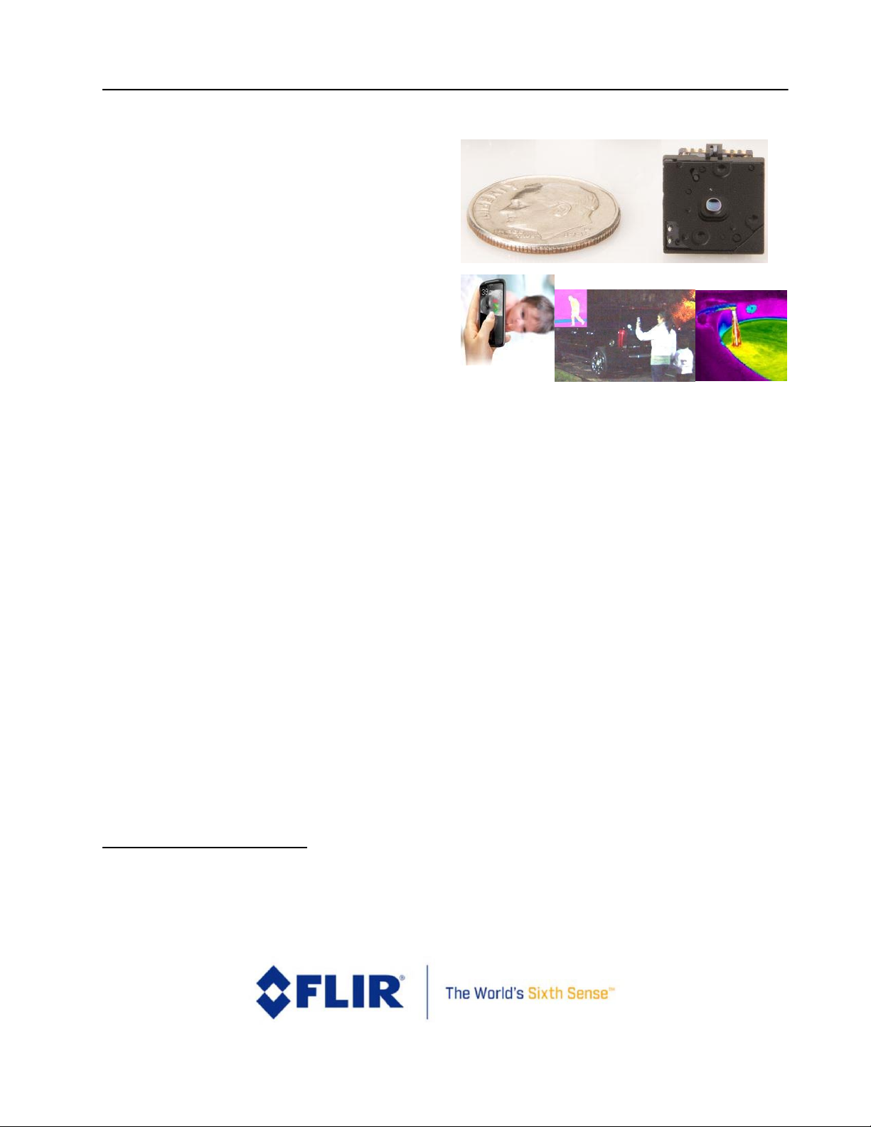
Lepton® is a complete long-wave infrared
(LWIR) camera module designed to interface
easily into native mobile-device interfaces and
other consumer electronics. It captures infrared
radiation input in its nominal response
wavelength band (from 8 to 14 microns) and
outputs a uniform thermal image with
radiometry1 to provide temperature image with
measurements.
Lepton Features2
• Integral shutter configurations
• Configurations with 25°, 50° and 57°
HFOV (f/1.1 silicon doublet)
• LWIR sensor, wavelength 8 to 14 µm
• Arrays with 80x60 and 160x120 active
pixels available
• Thermal sensitivity <50 mK
• Integrated digital thermal image
processing functions, including
automatic thermal environment
compensation, noise filters, nonuniformity correction, and gain control
• Radiometric accuracy
1
(35°C blackbody)
o High gain: ±5C @ 25°C
o Low gain ±10C @ 25°C
• Radiometric Leptons
1
feature
temperature measurement including
per pixel and frame radiometric output
(TLinear) and Spotmeter
• Export compliant frame rate (< 9 Hz)
• SPI video interface
• Two-wire I2C serial control interface
1
Radiometric Leptons are 2.5 and 3.5.
• Uses standard cell-phone-compatible
power supplies: 2.8 V to sensor, 1.2 V to
digital core, and flexible IO from 2.8 V
to 3.1 V
• Fast time to image (< 1.2 sec)
• Low operating power
o Nominally 160 mW
o 800mW typical during shutter
event (~1s)
o Low power mode 5 mW
• RoHS compliant
• 32- pin socket interface to standard
Molex or similar side-contact connector
Applications
• Mobile phones
• Gesture recognition
• Building automation
• Thermal imaging
• Night vision
2
All specifications subject to change without notice
Page 2

FLIR LEPTON® Engineering Datasheet
The information contained herein does not contain technology as defined by the EAR, 15 CFR 772, is publicly available,
and therefore, not subject to EAR. NSR (6/14/2018).
Information on this page is subject to change without notice.
Lepton Engineering Datasheet, Document Number: 500-0659-00-09 Rev: 203
2
Contents
1 INTRODUCTION ............................................................................................................................................................. 6
1.1 REVISION HISTORY ............................................................................................................................................................. 6
1.2 CONTACT US ..................................................................................................................................................................... 6
1.3 REFERENCES ..................................................................................................................................................................... 6
1.4 DEVICE OVERVIEW ............................................................................................................................................................. 8
1.5 KEY SPECIFICATIONS ........................................................................................................................................................... 9
1.6 SYSTEM ARCHITECTURE .................................................................................................................................................... 11
2 FUNCTIONAL DESCRIPTION ......................................................................................................................................... 12
2.1 FPA INTERFACE MODULE.................................................................................................................................................. 12
2.2 SYSTEM CONTROL (SYS CTRL) MODULE ............................................................................................................................... 12
2.3 POWER MANAGEMENT MODULE ....................................................................................................................................... 13
2.4 SOFTWARE-BASED VIDEO PROCESSING (SVP CORE) MODULE .................................................................................................. 13
2.5 MEMORY SYSTEM (MEMORY SYS) MODULE ......................................................................................................................... 13
2.6 GENERAL PURPOSE PROCESSOR (GPP) ................................................................................................................................ 13
2.7 VIDEO INTERFACE MODULE (VIDEO IF) ................................................................................................................................ 13
2.8 ONE-TIME PROGRAMMABLE MEMORY (OTP) ...................................................................................................................... 13
2.9 STATIC RANDOM-ACCESS MEMORY (SRAM) ....................................................................................................................... 13
2.10 GPIO INTERFACE MODULE (GPIO IF) ................................................................................................................................. 14
2.11 VIDEO PIPELINE ............................................................................................................................................................... 14
2.11.1 NUC .................................................................................................................................................................... 14
2.11.2 Defect Replacement ........................................................................................................................................... 14
2.11.3 Spatial / Temporal Filtering ............................................................................................................................... 14
2.11.4 AGC .................................................................................................................................................................... 15
2.11.5 Colorize .............................................................................................................................................................. 15
2.12 MASTER CLOCK ............................................................................................................................................................... 15
3 OPERATING STATES AND MODES ................................................................................................................................ 15
3.1 POWER STATES ............................................................................................................................................................... 15
3.2 FFC STATES .................................................................................................................................................................... 18
3.3 GAIN STATES .................................................................................................................................................................. 22
3.4 TELEMETRY MODES ......................................................................................................................................................... 23
3.5 RADIOMETRY MODES ....................................................................................................................................................... 29
Page 3

FLIR LEPTON® Engineering Datasheet
The information contained herein does not contain technology as defined by the EAR, 15 CFR 772, is publicly available,
and therefore, not subject to EAR. NSR (6/14/2018).
Information on this page is subject to change without notice.
Lepton Engineering Datasheet, Document Number: 500-0659-00-09 Rev: 203
3
3.5.1 Radiometry Enabled - TLinear ................................................................................................................................ 30
3.5.2 Radiometry Enabled – Flux linear ........................................................................................................................... 30
3.5.3 Radiometry Disabled .............................................................................................................................................. 31
3.5.4 Radiometric Accuracy – Module ............................................................................................................................. 32
3.5.5 Radiometric Accuracy – System Considerations ..................................................................................................... 32
3.6 AGC MODES .................................................................................................................................................................. 34
3.7 VIDEO OUTPUT FORMAT MODES ....................................................................................................................................... 36
3.8 GPIO MODES ................................................................................................................................................................. 39
4 INTERFACE DESCRIPTIONS ........................................................................................................................................... 40
4.1 COMMAND AND CONTROL INTERFACE ................................................................................................................................. 40
4.1.1 User Defaults Feature ............................................................................................................................................. 42
4.2 VOSPI CHANNEL ............................................................................................................................................................. 44
4.2.1 VoSPI Physical Interface ......................................................................................................................................... 45
4.2.2 VoSPI Protocol – Lepton 1.5, 1.6, 2.0 and 2.5 ......................................................................................................... 46
4.2.3 VoSPI Protocol – Lepton 3.0 and 3.5 ...................................................................................................................... 54
4.2.4 VoSPI Protocol – Lepton 2 vs. Lepton 3 .................................................................................................................. 62
5 THERMAL CAMERA BASICS .......................................................................................................................................... 63
6 MOUNTING SPECIFICATIONS ....................................................................................................................................... 65
6.1 SOCKET INFORMATION ..................................................................................................................................................... 66
6.2 MECHANICAL CONSIDERATIONS ......................................................................................................................................... 68
6.3 THERMAL CONSIDERATIONS ............................................................................................................................................... 69
6.4 OPTICAL CONSIDERATIONS ................................................................................................................................................ 69
7 IMAGE CHARACTERISTICS ............................................................................................................................................ 69
8 SPECTRAL RESPONSE ................................................................................................................................................... 71
9 ELECTRICAL SPECIFICATIONS ....................................................................................................................................... 73
9.1 LEPTON PIN-OUT ............................................................................................................................................................. 73
9.2 DC AND LOGIC LEVEL SPECIFICATIONS ................................................................................................................................. 76
9.3 AC ELECTRICAL CHARACTERISTICS ....................................................................................................................................... 77
9.4 ABSOLUTE MAXIMUM RATINGS ......................................................................................................................................... 78
9.5 ELECTRONIC INTEGRATION CONSIDERATIONS ......................................................................................................................... 78
10 ENVIRONMENTAL SPECIFICATIONS ............................................................................................................................. 79
10.1 COMPLIANCE WITH ENVIRONMENTAL DIRECTIVES .................................................................................................................. 80
11 ABBREVIATIONS AND ACRONYMS ............................................................................................................................... 82
Page 4

FLIR LEPTON® Engineering Datasheet
The information contained herein does not contain technology as defined by the EAR, 15 CFR 772, is publicly available,
and therefore, not subject to EAR. NSR (6/14/2018).
Information on this page is subject to change without notice.
Lepton Engineering Datasheet, Document Number: 500-0659-00-09 Rev: 203
4
Table of Figures
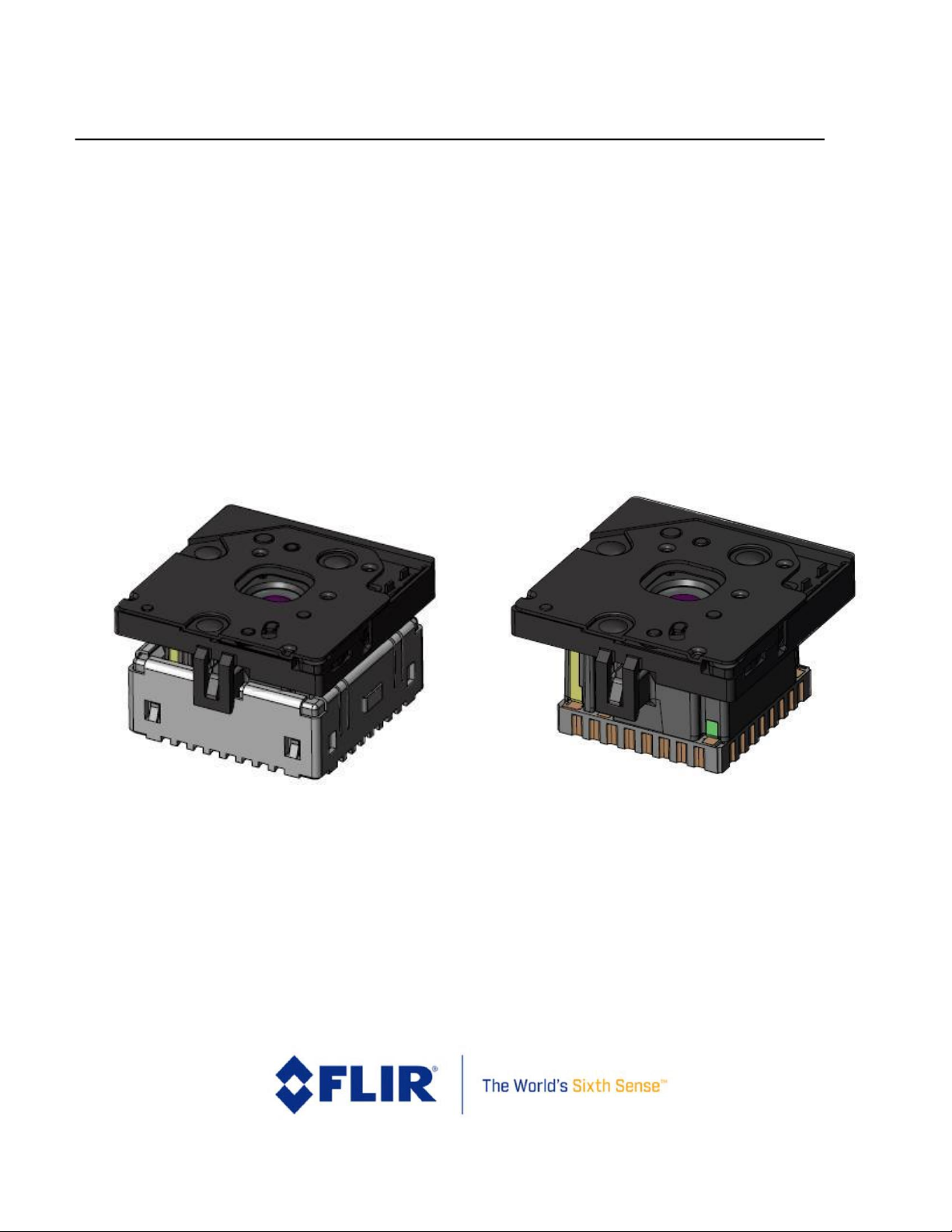
Figure 1. Lepton with shutter Camera (with and without socket) .............................................................................8
Figure 2 - Lepton Architecture .................................................................................................................................. 11
Figure 3 - Lepton Detailed Block Diagram ................................................................................................................ 12
Figure 4 - Lepton Video Pipeline Block Diagram ...................................................................................................... 14
Figure 5 - State Diagram Showing Transitions among the Five Power States ........................................................ 16
Figure 6 - Lepton Power Sequencing ........................................................................................................................ 18
Figure 7 - Examples of Good Uniformity, Graininess, and Blotchiness ................................................................... 19
Figure 8 - FFC States .................................................................................................................................................. 21
Figure 9 - Relative Spatial Noise after FFC vs. Number of Integrated Frames ((defaults is 8) ............................... 22
Figure 10 - Hypothetical Illustration of Camera Output in counts vs. Camera Temperature in Radiometry-
enabled Mode ........................................................................................................................................................... 31
Figure 11 - Hypothetical Illustration of Camera Output vs. Camera Temperature in Radiometry-disabled Mode
................................................................................................................................................................................... 32
Figure 12 - Illustration of a Histogram for a 3x3 Pixel Area..................................................................................... 35
Figure 13 - Comparison of Linear AGC and Classic/Lepton Variant of Histogram Equalization ............................. 36
Figure 14 - Built-in Color Palette .............................................................................................................................. 38
Figure 15 - Comparison of an Identical Image with Grayscale and a False-color Palette ...................................... 39
Figure 16 - VoSPI Flexible Clock Rate ....................................................................................................................... 45
Figure 17 - VoSPI I/O ................................................................................................................................................. 45
Figure 18 - SPI Mode 3 (CPOL=1, CPHA=1) ............................................................................................................... 46
Figure 19 - SPI Bit Order (transmission of 0x8C08) .................................................................................................. 46
Figure 20 - Generic VoSPI Packet .............................................................................................................................. 47
Figure 21 - Video Packet ........................................................................................................................................... 48
Figure 22 - Discard Packet ......................................................................................................................................... 48
Figure 23 - Raw14 Mode: 1 video line per 160-byte payload .................................................................................. 49
Figure 24 - RGB888 Mode: 1 video line per 240-byte payload ................................................................................ 49
Figure 25 - Frame Counter for Successive 80x60 Frames ........................................................................................ 51
Figure 26 - Valid Frame Timing (no loss of synchronization) ................................................................................... 52
Figure 27 -Clock Too Slow - Failure to Read an Entire Frame Within the Frame Period ........................................ 53
Figure 28 - Intra-Frame Delay Too Long - Failure to Read Out an Entire Frame Before the Next is Available ...... 53
Page 5

FLIR LEPTON® Engineering Datasheet
The information contained herein does not contain technology as defined by the EAR, 15 CFR 772, is publicly available,
and therefore, not subject to EAR. NSR (6/14/2018).
Information on this page is subject to change without notice.
Lepton Engineering Datasheet, Document Number: 500-0659-00-09 Rev: 203
5
Figure 29 - Failure to Read Out an Available Frame ................................................................................................ 53
Figure 30 - Generic VoSPI Packet .............................................................................................................................. 55
Figure 31 - Segment and Packet Relationship to the 160x120 video image ........................................................... 55
Figure 32 - Packet Header Encoding and an Example .............................................................................................. 56
Figure 33 - Discard Packet ......................................................................................................................................... 57
Figure 34 - Raw14 Mode: 1 video line per 160-byte payload .................................................................................. 58
Figure 35 - RGB888 Mode: 1 video line per 240-byte payload ................................................................................ 58
Figure 36 - Location of Telemetry Lines ................................................................................................................... 58
Figure 37 - Frame Counter for Successive Frames .................................................................................................... 60
Figure 38 - Valid Frame Timing (no loss of synchronization) ................................................................................... 61
Figure 39 - Clock Too Slow - Failure to Read an Entire Frame Within the Frame Period ....................................... 61
Figure 40 - Intraframe Delay Too Long - Failure to Read Out an Entire Frame Before the Next is Available ........ 62
Figure 41 - Failure to Read Out an Available Frame ................................................................................................ 62
Figure 42 - Illustration of Lepton Detector Time Constant ...................................................................................... 64
Figure 43 - Lepton with Radiometry Camera Mounting Dimensions ...................................................................... 65
Figure 44 - Two Commercially-available Sockets (both from Molex) Compatible with Lepton ............................ 66
Figure 45 - Both Sockets Mounted on a PCB ............................................................................................................ 67
Figure 46 - Recommended Approach to Retaining Lepton in the end Application ................................................ 68
Figure 47 - Normalized Response as a Function of Signal Wavelength for Lepton 1.5, 2.0 and 2.5 ...................... 71
Figure 48 - Normalized Response as a Function of Signal Wavelength for Lepton 3.0 and 3.5 ............................. 72
Figure 49 - Pinout Diagram (viewed from bottom of camera module) .................................................................. 73
Figure 50. Example of Lepton schematic. ................................................................................................................ 78
Page 6

FLIR LEPTON® Engineering Datasheet
The information contained herein does not contain technology as defined by the EAR, 15 CFR 772, is publicly available,
and therefore, not subject to EAR. NSR (6/14/2018).
Information on this page is subject to change without notice.
Lepton Engineering Datasheet, Document Number: 500-0659-00-09 Rev: 203
6
1 Introduction
1.1 Revision History
Revision
Date
Description of Change
100
05/03/2016
Lepton with Radiometry release
110
11/12/2016
Updates to include low gain mode feature details
200
03/21/2018
Consolidating all Lepton current configurations into one
datasheet. Older document numbers are 500-0771-01-09, 5000763-01-09, 500-0726-01-09.
201
04/06/2018
Corrected part number for Lepton 1.5. Minor editorial changes.
Added document number.
202
07/02/2018
Updated dimensions and weight.
203
08/28/2018
Clarified validity of scene dynamic range.
Updated EAR statement.
Clarified that THousing in telemetry is only supported for Lepton
2.5 and 3.5.
1.2 Contact Us
email: SBA-CORES@FLIR.COM
http://www.FLIR.com
1.3 References
110-0144-04 Lepton Software Interface Description Document (pdf)
80x60 Lepton VoSPI Developer Guide (pdf)
110-0144-50 Lepton VoSPI Developers Guide (pdf) (For 160x120)
Lepton_Example_Schematic_CAD_r100.DSN (Cadence-Capture schematic CAD file)
Lepton_Example_Schematic_CAD_r100.pdf (Cadence-Capture schematic PDF file)
Lepton_Example_Schematic_CAD_r100.brd (Cadence-Allegro PCB layout CAD file)
102-PS245-75 Advanced Radiometry App Note (pdf)
Configuration
Mechanical IDD
1.5
500-0643-41.pdf
1.6
500-0690-41.pdf
Page 7

FLIR LEPTON® Engineering Datasheet
The information contained herein does not contain technology as defined by the EAR, 15 CFR 772, is publicly available,
and therefore, not subject to EAR. NSR (6/14/2018).
Information on this page is subject to change without notice.
Lepton Engineering Datasheet, Document Number: 500-0659-00-09 Rev: 203
7
2.0
500-0659-41.pdf
2.5
500-0763-41.pdf
3.0
500-0726-41.pdf
3.5
500-0771-41.pdf
Page 8
FLIR LEPTON® Engineering Datasheet
The information contained herein does not contain technology as defined by the EAR, 15 CFR 772, is publicly available,
and therefore, not subject to EAR. NSR (6/14/2018).
Information on this page is subject to change without notice.
Lepton Engineering Datasheet, Document Number: 500-0659-00-09 Rev: 203
8
Figure 1. Lepton with shutter Camera (with and without socket)
1.4 Device Overview
Lepton is an infrared camera system that integrates a fixed-focus lens assembly, an 80x60 or 160x120 long-wave
infrared (LWIR) microbolometer sensor array, and signal-processing electronics. Some configurations are also
provided with an integral shutter assembly that is used to automatically optimize image uniformity on a periodic
basis. Easy to integrate and operate, Lepton is intended for mobile devices as well as any other application
requiring very small footprint, very low power, and instant-on operation. Lepton can be operated in its default
mode or configured into other modes through a command and control interface (CCI).
Figure 1 shows a view of the Lepton with Radiometry camera as standalone and mounted in a socket.
Page 9

FLIR LEPTON® Engineering Datasheet
The information contained herein does not contain technology as defined by the EAR, 15 CFR 772, is publicly available,
and therefore, not subject to EAR. NSR (6/14/2018).
Information on this page is subject to change without notice.
Lepton Engineering Datasheet, Document Number: 500-0659-00-09 Rev: 203
9
1.5 Key Specifications
Table 1- Key Specifications
All numbers are nominal unless tolerances are specified.
Available configurations
Part number
Array format
Horizontal field of view
Shutter
Thermal
radiometry
Distortion (barrel)
Scene Dynamic range
3
-
High gain (Low gain)
Pixel pitch
Lepton 1.5: 500-0643-00
80 x 60
50°
No - <8%
-10 °C to +140 °C
17 μm
Lepton 1.6: 500-0690-00
80 x 60
25°
No - <3%
-10 °C to +140 °C
17 μm
Lepton 2.0: 500-0659-01
80 x 60
50°
Yes - <8%
-10 °C to +140 °C
17 μm
Lepton 2.5: 500-0763-01
80 x 60
50°
Yes
Yes
<8%
-10 °C to +140 °C
(-10°C to 450°C)
17 μm
Lepton 3.0: 500-0726-01
160 x 120
57°
Yes - <13%
-10 °C to +140 °C
12 μm
Lepton 3.5: 500-0771-01
160 x 120
57°
Yes
Yes
<13%
-10 °C to +140 °C
(-10°C to 400°C)
12 μm
Overview
Sensor technology
Uncooled VOx microbolometer
Spectral range
Longwave infrared, 8 μm to 14 μm
Video scan
Progressive
Effective frame rate4
8.7 Hz (exportable)
Thermal sensitivity
<50 mK (0.050°C)
Temperature compensation
Automatic. Output image independent of camera
temperature.
3
Scene Dynamic Range is specified at room temperature and may vary over ambient temperature. It is typically somewhat
reduced at lower operating temperature.
4
Lepton 1.5, 1.6, 2.0, 2.5 stream video at 26Hz with every 3 frames repeated (effectively 8.7Hz). Lepton 3.0 and 3.5 stream
segments of the images with effectively full frames at 8.7Hz. In this document, when referring to number of frames the
frame rate 26Hz is understood.
Page 10

FLIR LEPTON® Engineering Datasheet
The information contained herein does not contain technology as defined by the EAR, 15 CFR 772, is publicly available,
and therefore, not subject to EAR. NSR (6/14/2018).
Information on this page is subject to change without notice.
Lepton Engineering Datasheet, Document Number: 500-0659-00-09 Rev: 203
10
Output format
User-selectable 14-bit, 8-bit (AGC applied), or 24-bit RGB
(AGC and colorization applied)
Solar protection
Integral
Thermal radiometric
accuracy (Lepton 2.5 and 3.5)
- High gain mode: Greater of ±5 °C or 5% (typical)
- Low gain mode: Greater of ±10 °C or 10% (typical)
Electrical
Input clock
25-MHz nominal, CMOS IO Voltage Levels in accordance with
Electrical Specifications, page 73.
Video data interface
Video over SPI
Control port
CCI (I2C-like), CMOS IO Voltage Levels in accordance with
Electrical Specifications, page 73.
Input supply voltage
(nominal)
2.8 V, 1.2 V, 2.5 V to 3.1 V IO
Power dissipation
Nominally 150 mW at room temperature (operating), 5 mW
(standby). For 2.0, 2.5, 3.0 and 3.5 650mW during shutter
event.
Mechanical
Dimensions [mm] (w × l × h)
Lepton 1.5 (without shutter): 8.47 × 9.67 × 5.62
Lepton 1.6 (without shutter): 8.47 × 9.69 × 8.84
Lepton 2.0 (with shutter): 10.50 x 11.70 x 6.37
Lepton 2.5, 3.0, 3.5 (with shutter): 11.50 x 12.70 x 6.835
Dimensions with socket
105028-101 [mm] (w × l × h)
Lepton 1.5 (without shutter): 10.78 × 10.60 × 5.92
Lepton 1.6 (without shutter): 10.78 × 10.60 × 9.15
Lepton 2.0 (with shutter): 10.78 x 11.70 x 6.68
Lepton 2.5, 3.0, 3.5 (with shutter): 11.50 x 12.70 x 7.14
Weight (typical)
Lepton 1.5, 2.0: 0.68 grams
Lepton 2.5: 1.02 grams
Lepton 3.0, 3.5: 0.91 grams
Environmental
Camera operating
temperature range
Lepton 1.5, 1.6, 2.0, 2.5, 2.0, 3.5: -10 °C to +80 °C
Lepton 2.0, 3.0: Shutter operation limited to -10 °C to +65 °C
Non-operating temperature
range
-40 °C to +80 °C
Shock
1500 G @ 0.4 ms
Page 11
FLIR LEPTON® Engineering Datasheet
The information contained herein does not contain technology as defined by the EAR, 15 CFR 772, is publicly available,
and therefore, not subject to EAR. NSR (6/14/2018).
Information on this page is subject to change without notice.
Lepton Engineering Datasheet, Document Number: 500-0659-00-09 Rev: 203
11
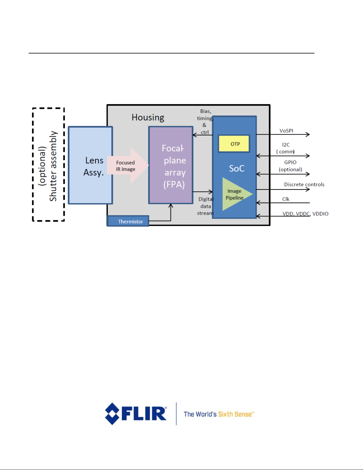
1.6 System Architecture
A simplified architectural diagram of the Lepton camera module is shown in Figure 2.
Figure 2 - Lepton Architecture
The lens assembly focuses infrared radiation from the scene onto an array of thermal detectors with 17m or
12m pitch. Each detector element is a vanadium-oxide (VOx) microbolometer whose temperature varies in
response to incident flux. The change in temperature causes a proportional change in each microbolometer’s
resistance. VOx provides a high temperature coefficient of resistance (TCR) and low 1/f noise, resulting in excellent
thermal sensitivity and stable uniformity. The microbolometer array is grown monolithically on top of a readout
integrated circuit (ROIC) to comprise the complete focal plane array (FPA).
For shuttered configurations, the shutter assembly periodically blocks radiation from the scene and presents a
uniform thermal signal to the sensor array, allowing an update to internal correction terms used to improve image
quality. For applications in which there is little to no movement of the Lepton camera relative to the scene (for
example, fixed-mount security applications), the shutter assembly is recommended. For applications in which
there is ample movement (for example, handheld applications), the shutter assembly is less essential although still
capable of providing slight improvement to image quality, particularly at start-up and when the ambient
temperature varies rapidly. The shutter is also used as a reference for improved radiometric performance.
Page 12
FLIR LEPTON® Engineering Datasheet
The information contained herein does not contain technology as defined by the EAR, 15 CFR 772, is publicly available,
and therefore, not subject to EAR. NSR (6/14/2018).
Information on this page is subject to change without notice.
Lepton Engineering Datasheet, Document Number: 500-0659-00-09 Rev: 203
12
The serial stream from the FPA is received by a system on a chip (SoC) device, which provides signal processing and
output formatting. This device is more fully defined in Functional Description, page 12.
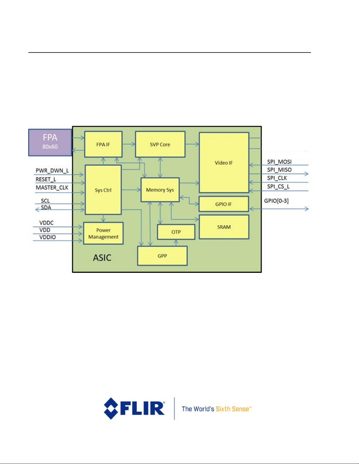
2 Functional Description
A detailed block diagram of the Lepton camera module is shown in Figure 3.
Figure 3 - Lepton Detailed Block Diagram
2.1 FPA Interface Module
The FPA Interface module generates timing and control signals to the FPA. It also receives and deserializes the
digital data stream from the FPA. The output values of on-board temperature sensors are multiplexed into the
pixel data stream, and the FPA Interface module strips these out and accumulates them (to improve SNR).
2.2 System Control (Sys Ctrl) Module
The System Control module provides the phase-lock-loop (PLL) and generates all clocks and resets required for
other modules. It also generates other timing events including syncs and the internal watchdog timer.
Additionally, it provides the boot controller, random-number generator, and command and control interface (CCI)
decode logic.
Page 13

FLIR LEPTON® Engineering Datasheet
The information contained herein does not contain technology as defined by the EAR, 15 CFR 772, is publicly available,
and therefore, not subject to EAR. NSR (6/14/2018).
Information on this page is subject to change without notice.
Lepton Engineering Datasheet, Document Number: 500-0659-00-09 Rev: 203
13
2.3 Power Management Module
The Power Management module controls the power switches, under direction from the System Control Module.
2.4 Software-based Video Processing (SVP Core) Module
The SVP Core module is an asymmetric multi-core digital signal processor (DSP) engine that provides the full video
pipeline, further described in Video Pipeline, page 14.
2.5 Memory System (Memory Sys) Module
The Memory System module provides the memory interface to all the other modules that require access to SRAM
and/or OTP.
2.6 General Purpose Processor (GPP)
The GPP is a central processing unit (CPU) that provides the following functionality:
• Servicing of CCI commands
• Initialization and configuration of the video pipeline
• Power management
• Other housekeeping functions
2.7 Video Interface Module (Video IF)
The Video Interface module receives video data and formats it for VoSPI protocol (see documents in References,
page 6).
2.8 One-Time Programmable Memory (OTP)
The OTP memory contains all the non-volatile data for the camera, including the software programs for the SVP
Core and GPP as well as calibration data and camera-unique data (such as serial number). There are no provisions
for directly writing to OTP memory outside of the Lepton factory, except the User Default values as described
below.
An optional User Default feature is available on some Lepton versions to configure the desired defaults (e.g. FFC
mode, radiometry configuration, etc.), and write these defaults once by the user to OTP. This feature removes the
needs for an initialization sequence at start-up to configure the desired run-time settings. See User Defaults
Feature, page 42.
2.9 Static Random-Access Memory (SRAM)
SRAM is the primary volatile memory utilized by all other modules.
Page 14
FLIR LEPTON® Engineering Datasheet
The information contained herein does not contain technology as defined by the EAR, 15 CFR 772, is publicly available,
and therefore, not subject to EAR. NSR (6/14/2018).
Information on this page is subject to change without notice.
Lepton Engineering Datasheet, Document Number: 500-0659-00-09 Rev: 203
14
2.10 GPIO Interface Module (GPIO IF)
The General-Purpose Input / Output (GPIO) Interface module implements the GPIO pins, which can be runtime
configured (see GPIO Modes, page 39).
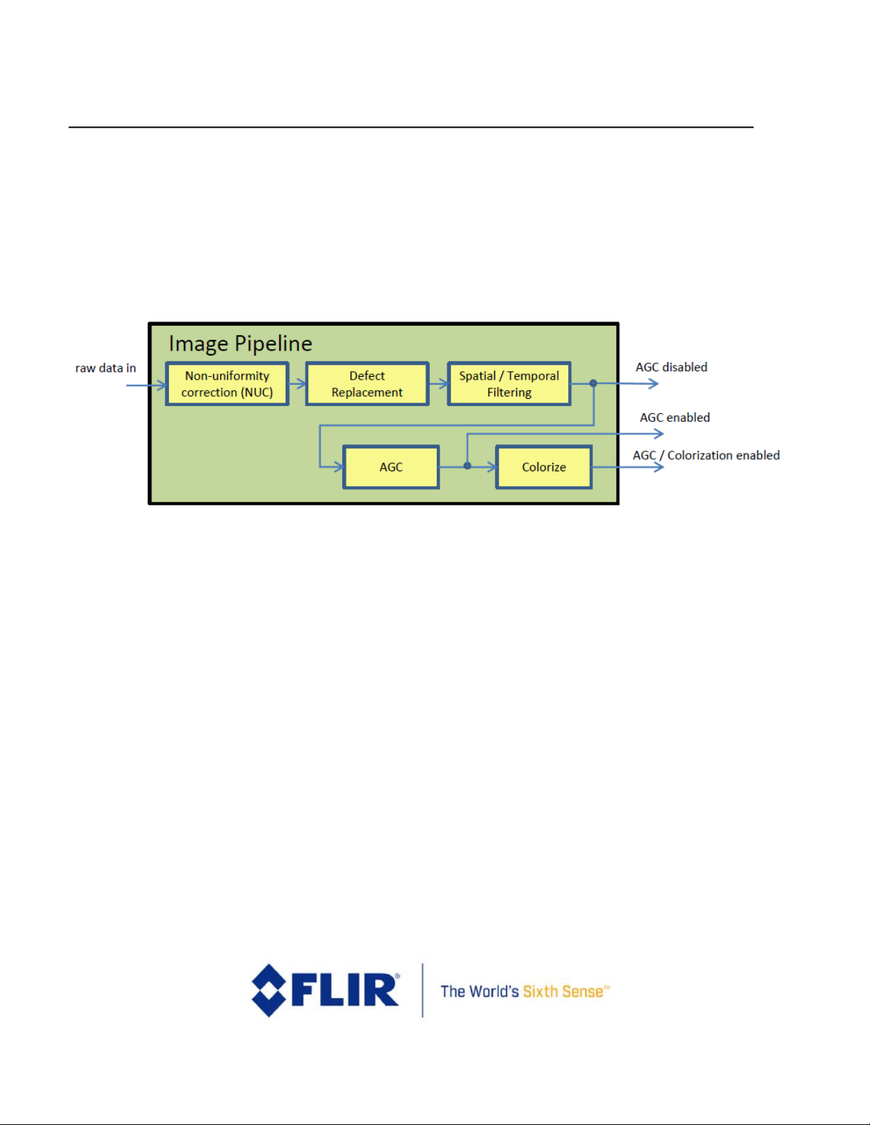
2.11 Video Pipeline
A block diagram of the video pipeline is shown in Figure 4.
Figure 4 - Lepton Video Pipeline Block Diagram
The video pipeline includes non-uniformity correction (NUC), defect replacement, spatial and temporal filtering,
automatic gain correction (AGC), and colorization.
2.11.1 NUC
The non-uniformity correction (NUC) block applies correction terms to ensure that the camera produces a
uniform output for each pixel when imaging a uniform thermal scene. Factory-calibrated terms are applied to
compensate for temperature effects, pixel response variations, and lens-illumination roll-off. To compensate for
temporal drift, the NUC block also applies an offset term that can be periodically updated at runtime via a process
called flat-field correction (FFC). The FFC process is further described in FFC States, page 18.
2.11.2 Defect Replacement
The defect-replacement block substitutes for any pixels identified as defective during factory calibration or during
runtime. The replacement algorithm assesses the values of neighboring pixels and calculates an optimum
replacement value.
2.11.3 Spatial / Temporal Filtering
The image pipeline includes several sophisticated image filters designed to enhance signal-to-noise ratio (SNR) by
eliminating temporal noise and residual non-uniformity. The filtering suite includes a scene-based non-uniformity
Page 15

FLIR LEPTON® Engineering Datasheet
The information contained herein does not contain technology as defined by the EAR, 15 CFR 772, is publicly available,
and therefore, not subject to EAR. NSR (6/14/2018).
Information on this page is subject to change without notice.
Lepton Engineering Datasheet, Document Number: 500-0659-00-09 Rev: 203
15
correction (SBNUC) algorithm which relies on motion within the scene to isolate fixed pattern noise (FPN) from
image content.
2.11.4 AGC
The AGC algorithm for converting the full-resolution (14-bit) thermal image into a contrast-enhanced image
suitable for display is a histogram-based non-linear mapping function. AGC Modes, page 34.
2.11.5 Colorize
The colorize block takes the contrast-enhanced thermal image as input and generates a 24-bit RGB color output.
See Video Output Format Modes, page 36.
2.12 Master Clock
In Lepton the master clock (MASTER_CLOCK) frequency is 25 MHz.
3 Operating States and Modes
Lepton provides several operating states and modes, more completely defined in the sections that follow:
• Power States, page 15
• FFC States, page 18
• Gain States page 22
• Telemetry Modes, page 23
• Radiometry Modes, page 29
• AGC Modes, page 34
• Video Output Format Modes, page 36
• GPIO Modes, page 39
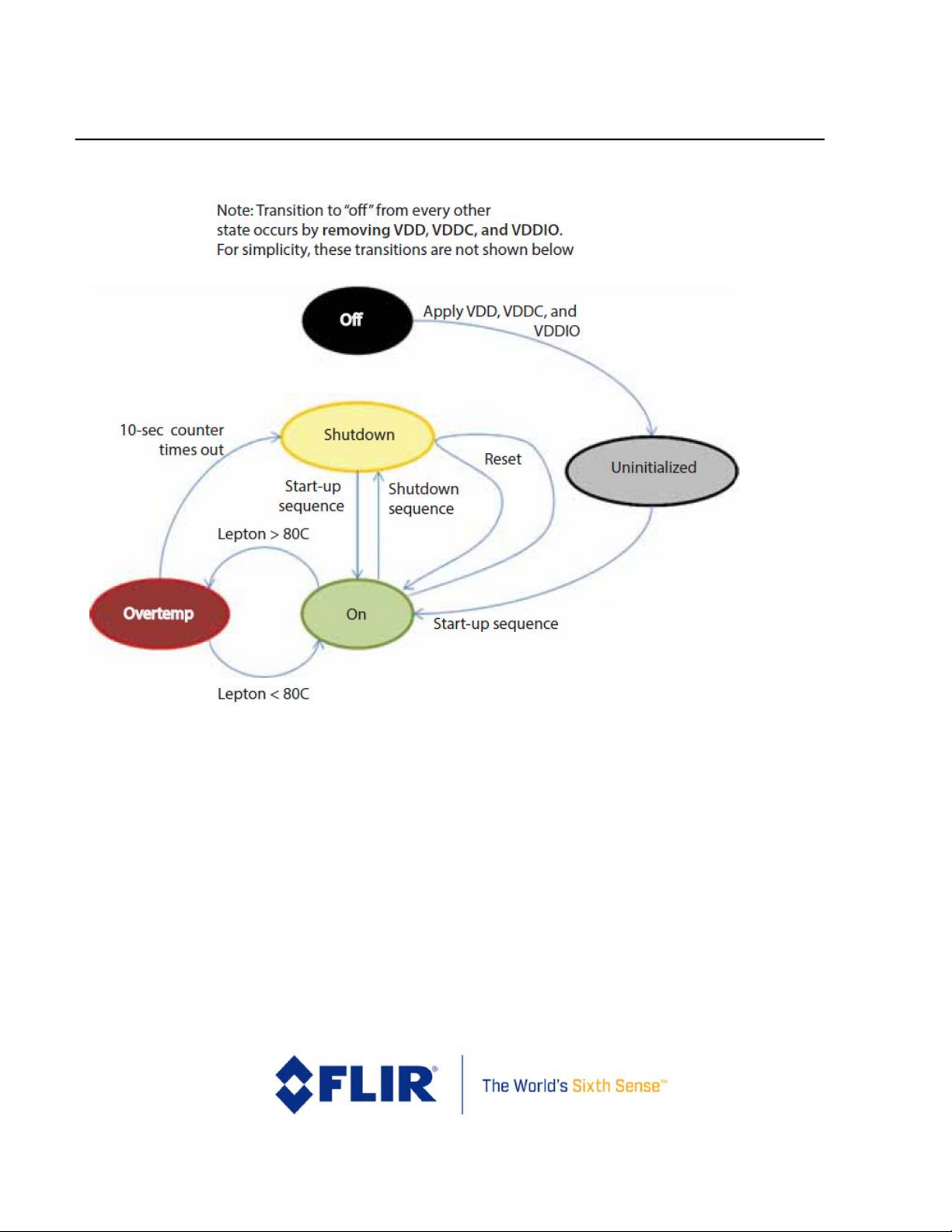
3.1 Power States
Lepton currently provides five power states. As depicted in the state diagram shown in Figure 5, most of the
transitions among the power states are the result of explicit action from the host. The automatic transition to and
from the over-temperature (Overtemp) state is an exception.
Page 16
FLIR LEPTON® Engineering Datasheet
The information contained herein does not contain technology as defined by the EAR, 15 CFR 772, is publicly available,
and therefore, not subject to EAR. NSR (6/14/2018).
Information on this page is subject to change without notice.
Lepton Engineering Datasheet, Document Number: 500-0659-00-09 Rev: 203
16
Figure 5 - State Diagram Showing Transitions among the Five Power States
The power states are listed here:
• Off: When no voltage is applied, Lepton is in the off state. In the off state, no camera
functions are available.
• Uninitialized: In the uninitialized state, all voltage forms are applied, but Lepton has not yet
been booted and is in an indeterminate state. It is not recommended to leave Lepton in this state
as power is not optimized; it should instead be booted to the on-state (and then transitioned
back to Shutdown if imaging is not required).
• On: In the on state, all functions and interfaces are fully available.
Page 17

FLIR LEPTON® Engineering Datasheet
The information contained herein does not contain technology as defined by the EAR, 15 CFR 772, is publicly available,
and therefore, not subject to EAR. NSR (6/14/2018).
Information on this page is subject to change without notice.
Lepton Engineering Datasheet, Document Number: 500-0659-00-09 Rev: 203
17
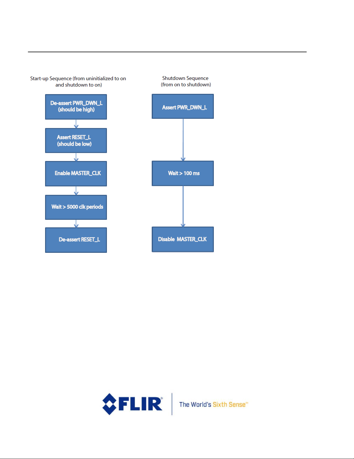
• Shutdown: In the shutdown state, all voltage forms are applied, but power consumption is
approximately 5 mW. In the shutdown state, no functions are available, but it is possible to
transition to the on state via the start-up sequence defined in Figure 6. The shutdown sequence
shown in Figure 6 is the recommended transition back to the shutdown state. It is also possible
to transition between shutdown and on states via software commands, as further defined in the
software IDD.
• Overtemp: The Overtemp state is automatically entered when the Lepton senses that its
temperature has exceeded approximately 80 °C. Upon entering the Overtemp state, Lepton
enables a “shutdown imminent” status bit in the telemetry line and starts a 10-second counter. If
the temperature of the Lepton falls below 80 °C before the counter times out, the “shutdown
imminent” bit is cleared and the system transitions back to the on state. If the counter does time
out, Lepton automatically transitions to the standby state.
Power sequencing is as shown in Figure 6.
Page 18
FLIR LEPTON® Engineering Datasheet
The information contained herein does not contain technology as defined by the EAR, 15 CFR 772, is publicly available,
and therefore, not subject to EAR. NSR (6/14/2018).
Information on this page is subject to change without notice.
Lepton Engineering Datasheet, Document Number: 500-0659-00-09 Rev: 203
18
Figure 6 - Lepton Power Sequencing
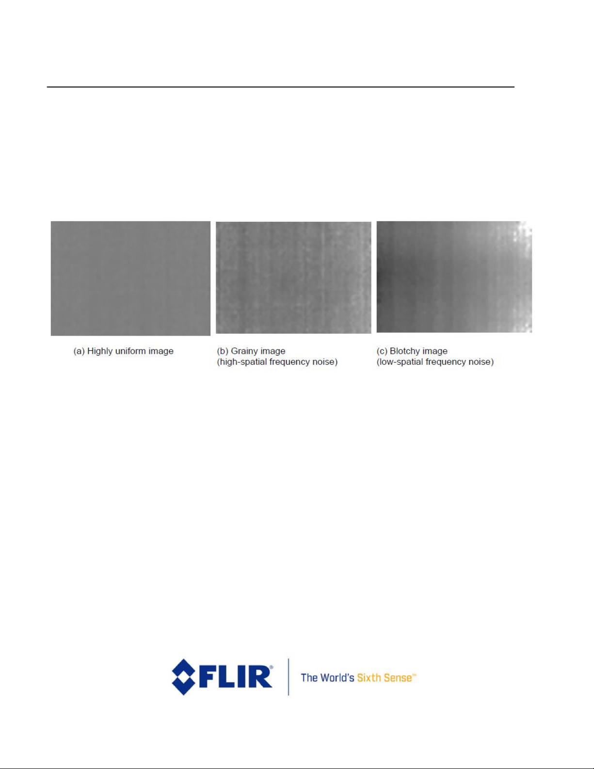
3.2 FFC States
Lepton is factory calibrated to produce an output image that is highly uniform, such as shown in Figure 7 (a),
when viewing a uniform-temperature scene. However, drift effects over long periods of time degrade uniformity,
resulting in imagery which appears grainier Figure 7 (b)) and/or blotchy (Figure 7 (c)). Columns and other pixel
combinations may drift as a group. These drift effects may occur even while the camera is powered off. Operation
over a wide temperature range (for example, powering on at -10 °C and heating to 65 °C without performing and
FFC) will also have a detrimental effect on image quality and radiometric accuracy.
For scenarios in which there is ample scene movement, such as most handheld applications, Lepton is capable of
automatically compensating for drift effects using an internal algorithm called scene-based non-uniformity
correction (scene-based NUC or SBNUC). However, for use cases in which the scene is essentially stationary, such
Page 19
FLIR LEPTON® Engineering Datasheet
The information contained herein does not contain technology as defined by the EAR, 15 CFR 772, is publicly available,
and therefore, not subject to EAR. NSR (6/14/2018).
Information on this page is subject to change without notice.
Lepton Engineering Datasheet, Document Number: 500-0659-00-09 Rev: 203
19
as fixed-mount applications, scene-based NUC is less effective. In stationary applications and those which need
highest quality or quickly available video, it is recommended to periodically perform a flat-field correction (FFC).
FFC is a process whereby the NUC terms applied by the camera's signal processing engine are automatically
recalibrated to produce the most optimal image quality. The sensor is briefly exposed to a uniform thermal scene,
and the camera updates the NUC terms to ensure uniform output. The entire FFC process takes less than a
second.
Figure 7 - Examples of Good Uniformity, Graininess, and Blotchiness
Lepton provides three different FFC modes:
• External (default for shutter-less configurations)
• Manual
• Automatic (default for configurations with shutter)
In external FFC mode, FFC is only executed upon command, and it should only be commanded when the camera
is imaging an external uniform source of a known temperature. To ensure radiometric accuracy in this mode, the
user must explicitly update the radiometry shutter mode to "User" and input the temperature of the scene during
FFC via the CCI. If in imaging mode only and temperature measurement is not required (radiometry disabled), any
uniform source such as a uniform wall will suffice.
Manual FFC mode is also executed only upon command, except that when FFC is commanded, Lepton closes its
integral shutter throughout the process. Note that it is not necessary to ensure a uniform external scene of a
known temperature before commanding FFC in manual FFC mode because the shutter serves as the uniform
source and includes a temperature sensor with automatic input for radiometric measurements.
Page 20

FLIR LEPTON® Engineering Datasheet
The information contained herein does not contain technology as defined by the EAR, 15 CFR 772, is publicly available,
and therefore, not subject to EAR. NSR (6/14/2018).
Information on this page is subject to change without notice.
Lepton Engineering Datasheet, Document Number: 500-0659-00-09 Rev: 203
20
In automatic FFC, the Lepton camera will automatically perform FFC under the following conditions:
• At start-up
• After a specified period of time (default of 3 minutes) has elapsed since the last FFC
• If the camera temperature has changed by more than a specified value (default of 1.5 Celsius degrees)
since the last FFC
The time trigger and the temperature-change trigger described above are both adjustable parameters via the CCI;
however, the default values are recommended under most operating conditions. Decreasing the temperature or
time interval to FFC more often will provide better radiometric accuracy, but the tradeoff is decrease in useful
camera output and radiometry readings due to the increased occurrence of FFC.
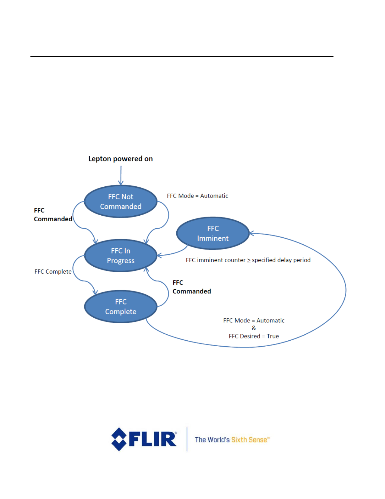
The current FFC state is provided through the telemetry line. There are four FFC states, enumerated below and
illustrated in Figure 8:
1. FFC not commanded (default): In this state, Lepton applies by default a set of factory-generated FFC
terms. In automatic FFC mode, this state is generally not seen because Lepton performs automatic
FFC at start-up.
2. FFC imminent: The camera only enters this state when it is operating in automatic FFC mode. The
camera enters “FFC imminent” state at a specified number of frames (default of 52 frames at 26Hz, or
approximately 2 seconds) prior to initiating an automatic FFC. The intent of this status is to warn the
host that an FFC is about to occur.
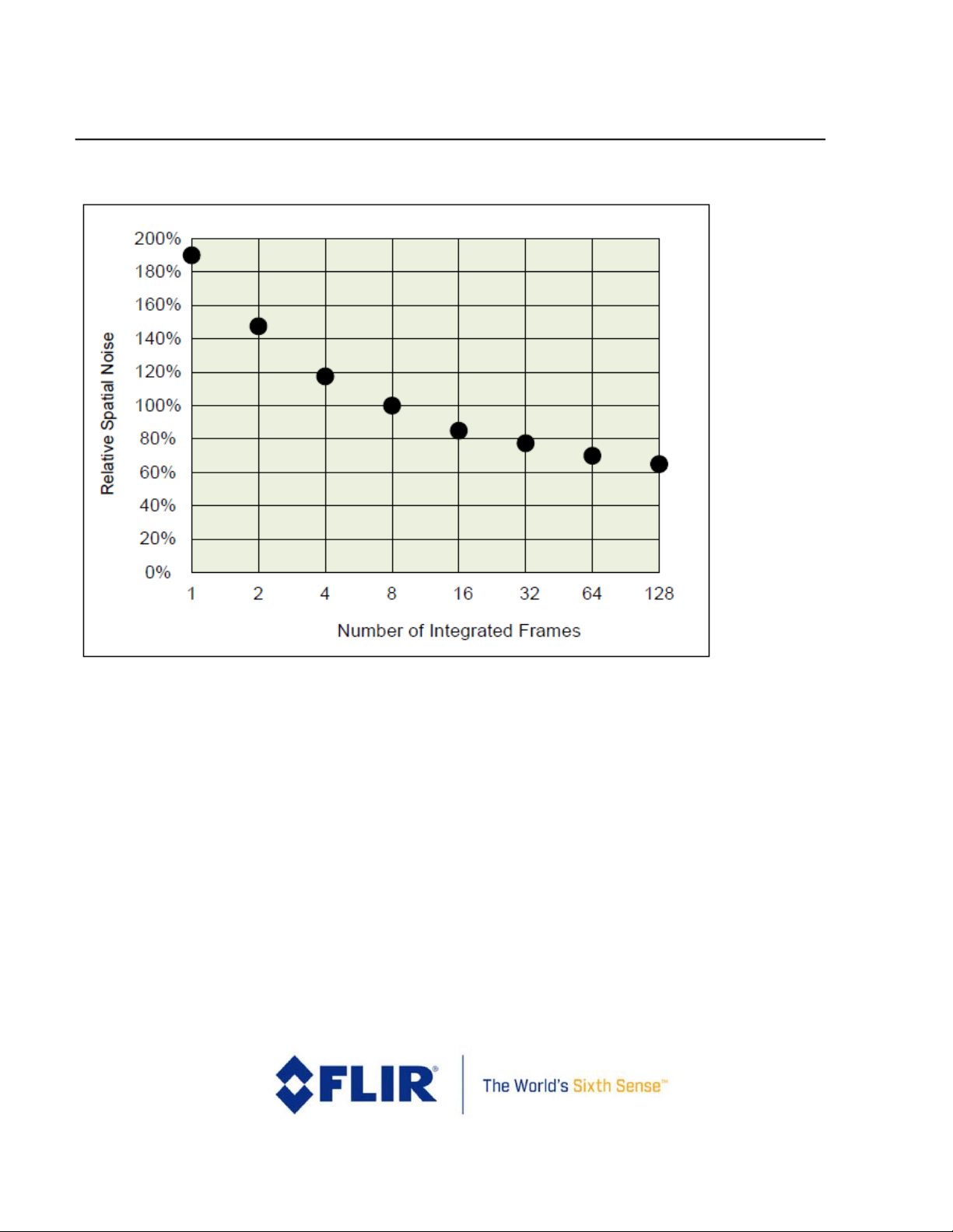
3. FFC in progress: Lepton enters this state when FFC is commanded from the CCI or when automatic
FFC is initiated. The default FFC duration is nominally 23 frames at 26Hz, in which case the camera
integrates 8 frames of output as the basis for the correction (the additional frames are overhead). It is
possible to configure the FFC to integrate fewer or more frames (from 1 to 128 in powers of 2).
Utilizing fewer frames obviously decreases the FFC period (with diminishing returns due to overhead)
whereas utilizing more frames provides greater reduction of spatial noise (also with diminishing
returns due to 1/f noise). Figure 9 quantifies the benefit. Radiometry readings are invalid during this
state.
4. FFC complete: Lepton automatically enters this state whenever a commanded or automatic FFC is
completed.
Lepton also provides an “FFC desired” flag in the telemetry line. The “FFC desired” flag is asserted under the same
conditions that cause automatic FFC when in automatic FFC mode. That is, the “FFC desired” flag is asserted at
start-up, when a specified period (default = 3 minutes) has elapsed since the last FFC, or when the sensor
temperature has changed by a specified value (default = 1.5 Celsius degrees) since the last FFC. In automatic
mode, the camera immediately enters “FFC imminent” state when “FFC desired” is true. In manual FFC mode and
Page 21
FLIR LEPTON® Engineering Datasheet
The information contained herein does not contain technology as defined by the EAR, 15 CFR 772, is publicly available,
and therefore, not subject to EAR. NSR (6/14/2018).
Information on this page is subject to change without notice.
Lepton Engineering Datasheet, Document Number: 500-0659-00-09 Rev: 203
21
external FFC mode, the “FFC desired” flag is intended to indicate to the host to command an FFC at the next
possible opportunity.
Lepton automatically prohibits the shutter from operating when it detects the temperature to be outside the
range -10°C to +80°C5. For example, if the camera is operating at a temperature of -15°C, no automatic FFC will be
performed, and the camera will ignore any commanded FFC if the FFC mode is “automatic” or “manual.” Normal
operation of the shutter will automatically resume when the temperature is back within the valid range. A status
flag is provided in the telemetry line indicating when shutter lockout is in effect.
Figure 8 - FFC States
5
Lepton 2.0 and 3.0 have an upper shutter lockout temperature set to 65 °C.
Page 22
FLIR LEPTON® Engineering Datasheet
The information contained herein does not contain technology as defined by the EAR, 15 CFR 772, is publicly available,
and therefore, not subject to EAR. NSR (6/14/2018).
Information on this page is subject to change without notice.
Lepton Engineering Datasheet, Document Number: 500-0659-00-09 Rev: 203
22
Figure 9 - Relative Spatial Noise after FFC vs. Number of Integrated Frames ((defaults is 8)
3.3 Gain States
Lepton 2.5 and 3.5 can be configured to operate in a high-gain state (the only available state in other versions of
Lepton) or a low-gain state. The high gain state provides lower NEDT and lower intra-scene range and the lowgain state provides higher NEDT but achieves higher intra-scene range. Lepton provides three different gainselection modes:
• High (default)
• Low
• Automatic
Page 23

FLIR LEPTON® Engineering Datasheet
The information contained herein does not contain technology as defined by the EAR, 15 CFR 772, is publicly available,
and therefore, not subject to EAR. NSR (6/14/2018).
Information on this page is subject to change without notice.
Lepton Engineering Datasheet, Document Number: 500-0659-00-09 Rev: 203
23
In high gain mode, the camera operates in the high gain state only. In low gain mode, the camera operates in the
low gain state only. In automatic gain mode, the camera software automatically selects between high and low
gain states based on the scene conditions and the following user-selectable parameters:
• High-to-low temperature / high-to-low population: The camera transitions to low gain when a
percentage of the pixel population greater than the user-defined population threshold is imaging a hotter
scene temperature than the user-defined temperature threshold
• Low-to-high temperature / low-to-high population: The camera transitions to high gain when a
percentage of the pixel population greater than the user-defined population threshold is imaging a colder
scene temperature than the user-defined temperature threshold
• Gain mode ROI: region of interest used for the calculations used to determine whether the scene
conditions (temperature and population) meet the criteria for a gain switch
Radiometry must be enabled to configure the camera software to automatic gain mode as scene temperature is
used as the metric to determine the gain mode switching behaviour. Note that an FFC is required upon gain
switch for uniformity and radiometric accuracy updates; therefore, the recommended FFC mode for automatic
gain mode is automatic FFC. In automatic gain mode and external of manual FFC mode, the camera will transition
to a different gain mode without an automatic FFC occurring and the user must initiate the FFC utilizing a
telemetry bit (e.g. effective gain state or FFC desired) to determine when the switch occurred and an FFC is
necessary.
3.4 Telemetry Modes
There are three telemetry modes that affect the video output signal:
• Telemetry disabled (default)
• Telemetry as header
• Telemetry as footer
Explicit commands over the CCI select each mode. The contents and encoding of the telemetry data are shown in
Table 2.
Table 3 shows the encoding of the status bits (Telemetry Row A, Words 3 and 4).
Page 24

FLIR LEPTON® Engineering Datasheet
The information contained herein does not contain technology as defined by the EAR, 15 CFR 772, is publicly available,
and therefore, not subject to EAR. NSR (6/14/2018).
Information on this page is subject to change without notice.
Lepton Engineering Datasheet, Document Number: 500-0659-00-09 Rev: 203
24
Table 2 - Telemetry Data Content and Encoding
Telemetry
Row
Word
start
Word
End
Number
of 16-bit
Words
Name
Notes
A 0 0 1 Telemetry
Revision
Format = major (byte 1), minor rev (byte 0).
A 1 2
2
Time Counter
32-bit counter in units of msec elapsed since
boot-up
A 3 4
2
Status Bits
See Table 3
A
5
12
8
Module serial #
A
13
16
4
Software revision
A
17
19
3
Reserved
A
20 21 2
Frame Counter
32-bit counter of output frames
A
22
22
1
Frame Mean
A
23
23 1 FPA Temp
In counts (prior to conversion to Kelvin)
A
24 24 1
FPA Temp
In Kelvin x 100
A
25
25
1
Housing Temp
In counts (prior to conversion to Kelvin)
Lepton 2.5, 3.5
A
26 26 1
Housing Temp
In Kelvin x 100
Lepton 2.5, 3.5
A
27
28
2
Reserved
A
29 29 1
FPA Temp at last
FFC
Updated every FFC. Units are Kelvin x100
Page 25

FLIR LEPTON® Engineering Datasheet
The information contained herein does not contain technology as defined by the EAR, 15 CFR 772, is publicly available,
and therefore, not subject to EAR. NSR (6/14/2018).
Information on this page is subject to change without notice.
Lepton Engineering Datasheet, Document Number: 500-0659-00-09 Rev: 203
25
Telemetry
Row
Word
start
Word
End
Number
of 16-bit
Words
Name
Notes
A
30 31 2
Time Counter at
last FFC
Updated every FFC. Units are msec
A
32 32 1
Housing temp at
last FFC
Updated every FFC. Units are Kelvin x100.
Lepton 2.5, 3.5
A
33
33 1 Reserved
A
34
37
4
AGC ROI
(top, left, bottom, right)
A
38 38 1
AGC Clip-Limit
High
See AGC, page 15
A
39 39 1
AGC Clip-Limit
Low
A
40
71
32
Reserved
A
72 73 2
Video
Output
See Video Output Format Modes, page 36
A
74 74 1
Log2 of
FFC
See FFC States, page 18
A
75
79 5 Reserved
B 0 18
19
Reserved
B
19
19
1
Emissivity
Scaled by 8192
B
20
20
1
Background
Temperature
Temperature in Kelvin x 100
B
21
21
1
Atmospheric
Transmission
Scaled by 8192
B
22
22
1
Atmospheric
Temperature
Temperature in Kelvin x 100
B
23
23
1
Window
Transmission
Scaled by 8192
Page 26

FLIR LEPTON® Engineering Datasheet
The information contained herein does not contain technology as defined by the EAR, 15 CFR 772, is publicly available,
and therefore, not subject to EAR. NSR (6/14/2018).
Information on this page is subject to change without notice.
Lepton Engineering Datasheet, Document Number: 500-0659-00-09 Rev: 203
26
Telemetry
Row
Word
start
Word
End
Number
of 16-bit
Words
Name
Notes
B
24
24
1
Window
Reflection
Scaled by 8192
B
25
25
1
Window
Temperature
Temperature in Kelvin x 100
B
26
26
1
Window
Reflected
Temperature
Temperature in Kelvin x 100
B
27
79
53
Reserved
C 0 4
5
Reserved
C 5 5
1
Gain Mode6
0 = High, 1 = Low, 2 = Auto
C 6 6
1
Effective Gain
In Auto mode, 0 = High, 1 = Low
C 7 7
1
Gain Mode
Desired Flag
0 = current gain mode is desired, 1 = gain mode
switch desired
C 8 8
1
Temperature
Gain Mode
Threshold High to
Low (°C)
Temperature threshold in °C used to determine
when an Auto switch to Low gain mode (while in
High gain mode) should occur in Radiometry
enabled/TLinear disabled mode
C 9 9
1
Temperature
Gain Mode
Threshold Low to
High (°C)
Temperature threshold in °C used to determine
when an Auto switch to High gain mode (while in
Low gain mode) should occur in Radiometry
enabled/TLinear disabled mode
C
10
10
1
Temperature
Gain Mode
Threshold High to
Low (K)
Temperature threshold in Kelvin used to
determine when an Auto switch to Low gain mode
(while in High gain mode) should occur in TLinear
mode
6
See Gain States, page 21.
Page 27

FLIR LEPTON® Engineering Datasheet
The information contained herein does not contain technology as defined by the EAR, 15 CFR 772, is publicly available,
and therefore, not subject to EAR. NSR (6/14/2018).
Information on this page is subject to change without notice.
Lepton Engineering Datasheet, Document Number: 500-0659-00-09 Rev: 203
27
Telemetry
Row
Word
start
Word
End
Number
of 16-bit
Words
Name
Notes
C
11
11
1
Temperature
Gain Mode
Threshold Low to
High (K)
Temperature threshold in Kelvin used to
determine when an Auto switch to High gain
mode (while in Low gain mode) should occur in
TLinear mode
C
12
13
2
Reserved
C
14
14
1
Population Gain
Mode Threshold
High to Low
Population threshold in percent of the Gain Mode
ROI used to determine when an Auto switch to
Low gain mode (while in High gain mode) should
occur
C
15
15
1
Population Gain
Mode Threshold
Low to High
Population threshold in percent of the Gain Mode
ROI used to determine when an Auto switch to
High gain mode (while in Low gain mode) should
occur
C
16
21
6
Reserved
C
22
25
4
Gain Mode ROI
(startRow, startCol, endRow, endCol)
C
26
47
22
Reserved
C
48
48
1
TLinear Enable
True if enabled
C
49
49 1 TLinear
T-Linear resolution (0 = 0.1, 1 = 0.01)
C
50
50
1
Spotmeter Mean
Spotmeter mean value in Kelvin within ROI
C
51
51 1 Spotmeter
Maximum
Spotmeter max value in Kelvin within ROI
C
52
52 1 Spotmeter
Minimum
Spotmeter min value in Kelvin within ROI
C
53
53 1 Spotmeter
Population
Number of pixel in Spotmeter ROI
Page 28

FLIR LEPTON® Engineering Datasheet
The information contained herein does not contain technology as defined by the EAR, 15 CFR 772, is publicly available,
and therefore, not subject to EAR. NSR (6/14/2018).
Information on this page is subject to change without notice.
Lepton Engineering Datasheet, Document Number: 500-0659-00-09 Rev: 203
28
Telemetry
Row
Word
start
Word
End
Number
of 16-bit
Words
Name
Notes
C
54
54
1
Spotmeter ROI
Start Row
Spotmeter ROI starting row coordinate
C
55
55
1
Spotmeter ROI
Start Col
Spotmeter ROI starting column coordinate
C
56
56
1
Spotmeter ROI
End Row
Spotmeter ROI ending row coordinate
C
57
57
1
Spotmeter ROI
End Col
Spotmeter ROI ending column coordinate
C
58
79
22
Reserved
Page 29

FLIR LEPTON® Engineering Datasheet
The information contained herein does not contain technology as defined by the EAR, 15 CFR 772, is publicly available,
and therefore, not subject to EAR. NSR (6/14/2018).
Information on this page is subject to change without notice.
Lepton Engineering Datasheet, Document Number: 500-0659-00-09 Rev: 203
29
Table 3 - Status Bit Encoding (Telemetry Row A, words 3 and 4)
Bit start
Bit end
Number of
Bits
Name
Notes
0
2 3 Reserved
3 3 1
FFC Desired
7
0 = FFC not desired
1 = FFC desired
4 5 2
FFC State
7
00 = FFC never commanded
01 = FFC imminent
10 = FFC in progress
11 = FFC complete
6
11
6
Reserved
12
12
1
AGC State
0=Disabled
1=Enabled
13
14
2
Reserved
15
15
1
Shutter lockout
7
0 = Shutter not locked out
1 = Shutter locked out
(outside of valid temperature
range, -10°C to 80°C)
8
16
19
4
Reserved
20
20
1
Overtemp shut down imminent
Goes true 10 seconds before
shutdown (see Power
States, page 15)
21
31
11
Reserved
3.5 Radiometry Modes
The Lepton with Radiometry (2.5 and 3.5) includes multiple options for radiometry modes that affect the video
output signal:
7
See FFC States, page 21.
8
Lepton 2.0 and 3.0 have an upper shutter lockout temperature set to 65 °C.
Page 30

FLIR LEPTON® Engineering Datasheet
The information contained herein does not contain technology as defined by the EAR, 15 CFR 772, is publicly available,
and therefore, not subject to EAR. NSR (6/14/2018).
Information on this page is subject to change without notice.
Lepton Engineering Datasheet, Document Number: 500-0659-00-09 Rev: 203
30
• Radiometry enabled, TLinear enabled (default for Lepton 2.5 and 3.5)
• Radiometry enabled, TLinear disabled
• Radiometry disabled
3.5.1 Radiometry Enabled - TLinear
The radiometry enabled mode affects the transfer function between incident flux (scene temperature) and pixel
output. From an image-quality standpoint, both radiometry modes produce nearly identical performance (no
change in NEDT), and either mode is appropriate for strict imaging applications. However, for applications in
which temperature measurement is required, radiometry must be enabled to access the related calibration and
software features, such as TLinear and Spotmeter, which support these measurements. In radiometry enabled
mode, enabling the corresponding TLinear mode changes the pixel output from representing scene flux in 14-bit
digital counts to representing scene temperature values in Kelvin (multiplied by a scale factor to include
decimals). For example, with TLinear mode enabled with a resolution of 0.01, a pixel value of 30000 signifies that
the pixel is measuring 26.85°C (300.00K – 273.15K). The Lepton with Radiometry configuration is intended as a
fully radiometric camera; therefore, the factory defaults are defined to have both radiometry and TLinear modes
enabled.
With radiometry mode enabled (independent of TLinear state), the Spotmeter feature can utilized. The
Spotmeter returns the mean, maximum, and minimum temperature readings in Kelvin for a given frame and ROI
via the CCI and/or telemetry. The ROI coordinates are user-selectable via CCI to allow for readings confined to any
arbitrary size or location within the array.
The radiometric accuracy over the operational temperature range is typically within ±5°C or 5%. Integration into
an end-system and environment and/or scene differences can affect the radiometric performance. To address
these factors, user-configurable parameters are available in software to account for the difference between
calibration method at the factory and the final system and application. The parameters include scene emissivity,
atmospheric temperature and transmission, background temperature, and parameters to account for the
recommended window included on a fully integrated system (transmission, reflection, temperature, and reflected
temperature). For a more detailed discussion on radiometry principles, accuracy, and calibration, reference the
Radiometry Application Note.
Note that the following discussion assumes AGC is disabled (see AGC Modes, page 34). If AGC is enabled, the
differences between the two radiometry modes are completely obscured by the AGC algorithm. In other words,
with AGC enabled, any differences in signal output between radiometry-disabled and radiometry-enabled modes
are negligible.
3.5.2 Radiometry Enabled – Flux linear
Page 31

FLIR LEPTON® Engineering Datasheet
The information contained herein does not contain technology as defined by the EAR, 15 CFR 772, is publicly available,
and therefore, not subject to EAR. NSR (6/14/2018).
Information on this page is subject to change without notice.
Lepton Engineering Datasheet, Document Number: 500-0659-00-09 Rev: 203
31
With radiometry enabled, Lepton performs internal adjustments to the signal level such that in principle the
output is independent of the camera's own temperature. The resulting output for three different scene
temperatures is illustrated hypothetically in Figure 10. Notice in Figure 10 that the output is only a function of
scene temperature, not camera temperature (again, the figure is for illustration purposes only and not perfectly
representative. In practice, there is slight output variation as camera temperature changes, particularly when the
temperature change is rapid). Also notice that responsivity is also independent of camera temperature; that is,
the difference in output between two different scene temperatures is a constant, as opposed to in Figure 11 on
page 32, where it decreases with increasing camera temperature.
Figure 10 - Hypothetical Illustration of Camera Output in counts vs. Camera Temperature in
Radiometry-enabled Mode
3.5.3 Radiometry Disabled
With radiometry disabled, the output of a given pixel is intended to be in the lower quarter of the 14-bit range
(~4096) when viewing a scene with a temperature equal to the temperature of the camera.9 Furthermore, the
responsivity, which is defined as the change in pixel output value for a change in scene temperature, varies over
9
With Lepton 1.5, 1.6, 2.0 and 3.0, the output was intended to be in the middle of the 14-bit range (~8192) but was updated
to provide more scene dynamic range at the hotter end of the spectrum for the radiometric release.
Page 32

FLIR LEPTON® Engineering Datasheet
The information contained herein does not contain technology as defined by the EAR, 15 CFR 772, is publicly available,
and therefore, not subject to EAR. NSR (6/14/2018).
Information on this page is subject to change without notice.
Lepton Engineering Datasheet, Document Number: 500-0659-00-09 Rev: 203
32
the camera's operating temperature range. The resulting output for three different scene temperatures is
illustrated hypothetically in Figure 11 (note that the figure is for illustration purposes and not perfectly
representative).
Figure 11 - Hypothetical Illustration of Camera Output vs. Camera Temperature in Radiometrydisabled Mode
3.5.4 Radiometric Accuracy – Module
Lepton camera module radiometric accuracy in high gain mode is ±5°C @ 25°C against a 35°C blackbody for a
Lepton camera module (using a simple test board with no significant heat sources) at equilibrium and 1”
blackbody at 25cm, corrected for emissivity, and in a normal room environment. In high gain mode the intrascene temperature range is typically -10°C to 140°C.
Lepton camera module radiometric accuracy in low gain mode is ±10°C @ 25°C against a 35°C blackbody for a
Lepton camera module (using a simple test board with no significant heat sources) at equilibrium and 1”
blackbody at 25cm, corrected for emissivity, and in a normal room environment. In low gain mode the intrascene temperature range is typically -10°C to 450°C (or 400 °C for Lepton 3.5).
3.5.5 Radiometric Accuracy – System Considerations
Page 33

FLIR LEPTON® Engineering Datasheet
The information contained herein does not contain technology as defined by the EAR, 15 CFR 772, is publicly available,
and therefore, not subject to EAR. NSR (6/14/2018).
Information on this page is subject to change without notice.
Lepton Engineering Datasheet, Document Number: 500-0659-00-09 Rev: 203
33
The radiometric accuracy of the Lepton camera module depends primarily on the ambient and scene
temperature. The size, distance, and emissivity of the target are also factors. Extreme humidity, high
concentrations of certain gases such as CO2, and nearby extremely hot or cold objects may also affect
measurements and should be avoided during module tests. When measured against a 1” blackbody at 25cm,
corrected for target emissivity, and at thermal equilibrium under typical room conditions, the typical accuracy of
the Lepton module in high gain mode is per Table 4.
Table 4- Radiometric Accuracy over Conditions, High Gain
T Ambient
0°C
30°C
60°C
T Scene
10°C
±7°C
±7°C
±8°C
50°C
±6°C
±5°C
±5°C
100°C
±6°C
±5°C
±4°C
When the Lepton module is integrated into a system, there are additional error sources that must be considered.
Heat from nearby components such as electronic devices, motors and solenoids, and even heat from an
operator’s hand, may directly or indirectly increase the radiation falling on the sensor. Variable heat sources
should be avoided. It is important that the heat presented to the Lepton module from surrounding electronics
and other sources be consistent and symmetric about the Lepton module to make compensation effective. The
correction parameters are scalar values and cannot accommodate dynamic or gradient effects. In addition, when
a protective window is required, reductions of the amount of scene radiation from the window as well as direct
emissions and reflections from it, will alter the received radiation. The Lepton module provides methods to
correct for these effects.
When the Lepton camera module is used in a device with a protective window and surrounding heat sources, the
radiometric temperature reading can be improved by performing a gain and offset correction for best accuracy.
The gain and offset values are input as window transmission and window temperature parameters though the CCI
interface. After performing a recalibration at room temperature against two reference blackbodies and
programming these two parameters, the typical accuracy in high gain mode can be according to
Table 5.
Page 34

FLIR LEPTON® Engineering Datasheet
The information contained herein does not contain technology as defined by the EAR, 15 CFR 772, is publicly available,
and therefore, not subject to EAR. NSR (6/14/2018).
Information on this page is subject to change without notice.
Lepton Engineering Datasheet, Document Number: 500-0659-00-09 Rev: 203
34
Table 5 - Typical Radiometric Accuracy after Per Unit Calibration.
T Ambient
0°C
30°C
60°C
T Scene
10°C
±5°C
±5°C
±6°C
50°C
±5°C
±3°C
±3°C
100°C
±5°C
±4°C
±3°C
A protective window will also affect intra-scene temperature range. Any environmental or system factors that
reduce the flux received by the sensor will lower the lower limit, and raise the upper limit, of the range. Such
factors will also decrease sensitivity and possibly even accuracy, so should normally be kept to a minimum.
3.6 AGC Modes
There are two AGC modes:
• AGC disabled (default)
• AGC enabled (see AGC HEQ Output Scale Factor and AGC Calculation Enable State in the Software IDD for
additional, related options)
AGC is a process whereby the large dynamic range of the infrared sensor is collapsed to a range more appropriate
for a display system. For Lepton, this is a 14-bit to 8-bit conversion. In its most simplistic form, AGC can be a linear
mapping from 14-bit to 8-bit; however, a simple linear AGC is generally incapable of providing pleasing imagery in
all imaging conditions. For example, when a scene includes both cold and hot regions (for example, a hot object in
front of a cold background as illustrated in Figure 13), linear AGC can produce an output image in which most
pixels are mapped to either full black or full white with very little use of the gray-shades (8-bit values) in between.
Because of this limitation of linear AGC, a more sophisticated algorithm is preferred.
Similar to most AGC algorithms that optimize the use of gray-shades, Lepton's is histogram-based. Essentially a
histogram counts the number of pixels in each frame that have a given 14-bit value. Figure 12 illustrates the
concept for a 3x3 pixel area.
Page 35

FLIR LEPTON® Engineering Datasheet
The information contained herein does not contain technology as defined by the EAR, 15 CFR 772, is publicly available,
and therefore, not subject to EAR. NSR (6/14/2018).
Information on this page is subject to change without notice.
Lepton Engineering Datasheet, Document Number: 500-0659-00-09 Rev: 203
35
Figure 12 - Illustration of a Histogram for a 3x3 Pixel Area
Classic histogram equalization uses the cumulative histogram as a mapping function between 14-bit and 8-bit.
The intent is to devote the most gray-shades to those portions of the input range occupied by the most pixels. For
example, an image consisting of 60% sky devotes 60% of the available gray-shades to the sky, leaving only 40% for
the remainder of the image. By comparison, linear AGC “wastes” gray-shades when there are gaps in the
histogram, whereas classic histogram equalization allocates no gray-shades to the gaps. This behavior is in
principle an efficient use of the available gray-shades, but there are a few drawbacks:
• The resulting contrast between an object and a much colder (or hotter) background can be rendered poor
by the fact the algorithm “collapses” the separation between such that the object is only 1 gray-shade
above the background. This phenomenon is illustrated in Figure 13.
• Too much emphasis can be placed on background clutter, particularly when a mostly isothermal
background comprises a large fraction of the total image area. This is also illustrated in Figure 15.
• For scenes with low dynamic range or less content, both the Linear AGC and Classic HEQ algorithms allow
the application of a high amount of gain to the histogram, resulting in more contrast but increasing noise.
The Lepton AGC algorithm is a modified version of classic histogram equalization that mitigates these
shortcomings. One such modification is a parameter called “clip limit high.” It clips the maximum population of
any single bin, limiting the influence of heavily populated bins on the mapping function. Another parameter
utilized by the Lepton algorithm is called “clip limit low.” It adds a constant value to every non-zero bin in the
histogram, resulting in additional contrast between portions of the histogram separated by gaps. Figure 13 is an
example showing the benefit of the Lepton clip parameters.
Page 36
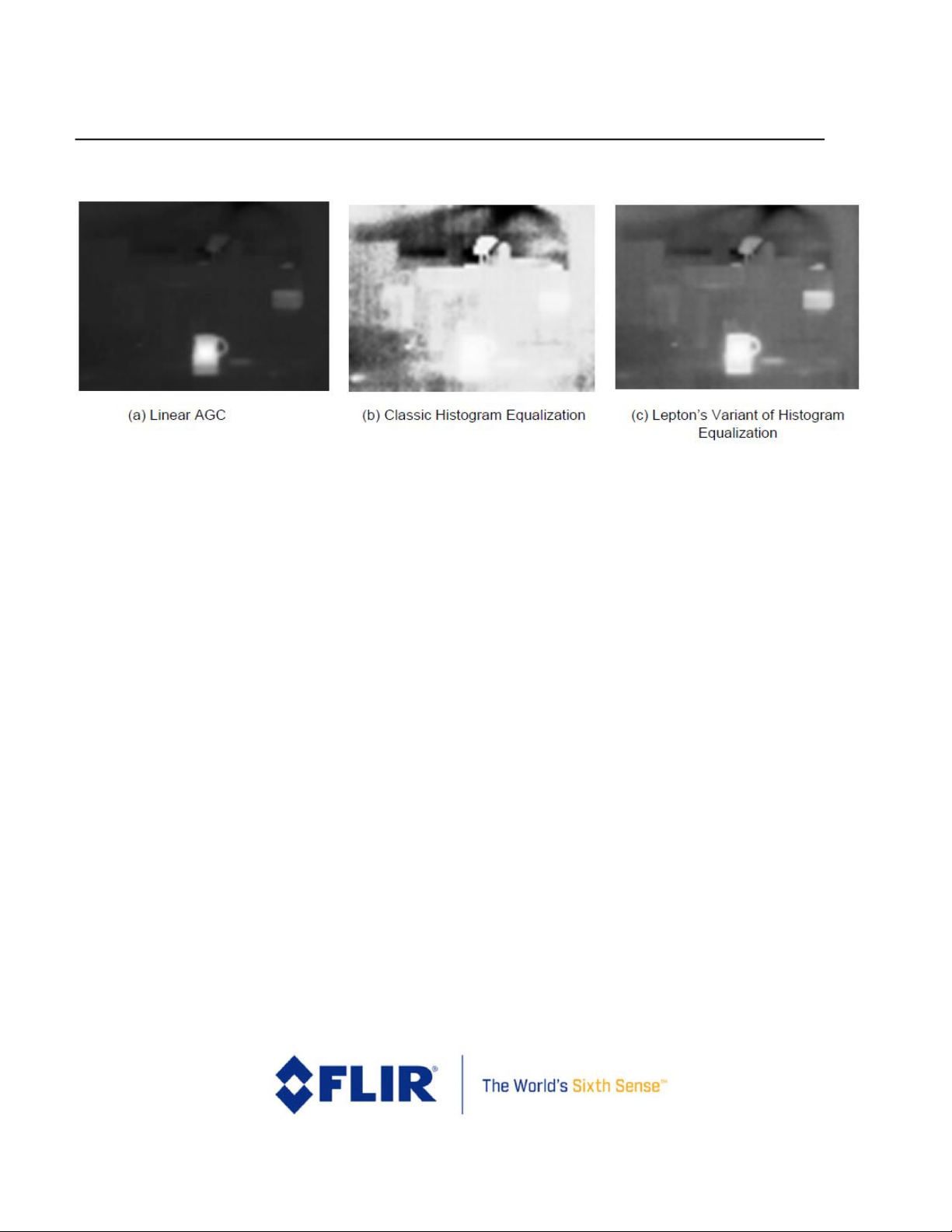
FLIR LEPTON® Engineering Datasheet
The information contained herein does not contain technology as defined by the EAR, 15 CFR 772, is publicly available,
and therefore, not subject to EAR. NSR (6/14/2018).
Information on this page is subject to change without notice.
Lepton Engineering Datasheet, Document Number: 500-0659-00-09 Rev: 203
36
Figure 13 - Comparison of Linear AGC and Classic/Lepton Variant of Histogram Equalization
A high value of clip limit high results in a mapping more like classic histogram equalization, whereas a low value
results in mapping more like linear AGC. For clip limit low, the opposite is true: a high value results in a mapping
more like linear AGC, whereas a low value results in a mapping more like classic histogram equalization. There
may be some overlap between the two parameters, but the difference between the two is that lowering the clip
limit high linearizes the brightness levels of the objects in the scene, while raising the clip limit low makes the
brightness of objects in the scene more representative of their temperature differences. The default values of
both parameters produce a good compromise between the two; however, because optimum AGC is highly
subjective and often application dependent, customers are encouraged to experiment to find settings most
appropriate for the target application.
By default, the histogram used to generate Lepton's 14-bit to 8-bit mapping function is collected from the full
array. In some applications, it is desirable to have the AGC algorithm ignore a portion of the scene when collecting
the histogram. For example, in some applications it may be beneficial to optimize the display to a region of
interest (ROI) in the central portion of the image. When the AGC ROI is set to a subset of the full image, any scene
content located outside of the ROI is not included in the histogram and therefore does not affect the mapping
function (note: this does not mean the portion outside of the ROI is not displayed or that AGC is not applied
there, only that those portions outside the AGC ROI do not influence the mapping function).
3.7 Video Output Format Modes
There are two video-output format modes:
Page 37

FLIR LEPTON® Engineering Datasheet
The information contained herein does not contain technology as defined by the EAR, 15 CFR 772, is publicly available,
and therefore, not subject to EAR. NSR (6/14/2018).
Information on this page is subject to change without notice.
Lepton Engineering Datasheet, Document Number: 500-0659-00-09 Rev: 203
37
• Raw14 (default)
10
• RGB888
The first mode is appropriate for viewing 14-bit data (AGC disabled), 16-bit TLinear data (AGC disabled,
TLinear enabled), or 8-bit data (AGC enabled) without colorization. The second mode is for viewing data
after application of the colorization look-up table (LUT) to generate 24-bit RGB data. This capability is further
described below. Note that the two output format modes result in different packet sizes for the VoSPI
output data (see VoSPI Protocol page 46). To properly view RGB888 data, the following order of operations
should be followed:
1. Disable telemetry if required (telemetry is not valid in RGB888 mode)
2. Enable AGC (colorization without AGC is not a valid permutation)
3. Select RGB888 mode
4. Synchronize or re-synchronize the VoSPI channel (see Establishing/Re-Establishing Sync, page 52)
5. Optional: Select a desired built-in LUT or upload a custom LUT.
The purpose of RGB888 mode is to generate a “false color” RGB image in which each grayscale value is converted
by means of a user-specified look-up table (typically called a color palette) to a particular color. Figure 14 shows
the 8 built-in color palettes provided in the current release of Lepton, and Figure 15 shows an example image
with a color palette applied. The built-in color palettes are selectable by means of the command and control
interface (see the Lepton Software Interface Description Document for more information on the palette format).
Additionally, a user-specified palette can be uploaded through the command and control interface.
10
Raw14 is a mode with 16 bits per pixel of which the two most significant bits are zero, except in TLinear mode, when
available.
Page 38

FLIR LEPTON® Engineering Datasheet
The information contained herein does not contain technology as defined by the EAR, 15 CFR 772, is publicly available,
and therefore, not subject to EAR. NSR (6/14/2018).
Information on this page is subject to change without notice.
Lepton Engineering Datasheet, Document Number: 500-0659-00-09 Rev: 203
38
Figure 14 - Built-in Color Palette
Page 39

FLIR LEPTON® Engineering Datasheet
The information contained herein does not contain technology as defined by the EAR, 15 CFR 772, is publicly available,
and therefore, not subject to EAR. NSR (6/14/2018).
Information on this page is subject to change without notice.
Lepton Engineering Datasheet, Document Number: 500-0659-00-09 Rev: 203
39
Figure 15 - Comparison of an Identical Image with Grayscale and a False-color Palette
3.8 GPIO Modes
There are two supported GPIO modes:
• Disabled (default)
• VSYNC enabled
In disabled mode, no signals are provided as input or output on the GPIO pins. In VSYNC mode, a video sync
signal is provided as an output on GPIO3. The purpose of this signal is more fully described in Frame
Synchronization, page 53.
NOTE: GPIO0, GPIO1, and GPIO2 should not be connected, regardless of the
selected GPIO mode.
Page 40

FLIR LEPTON® Engineering Datasheet
The information contained herein does not contain technology as defined by the EAR, 15 CFR 772, is publicly available,
and therefore, not subject to EAR. NSR (6/14/2018).
Information on this page is subject to change without notice.
Lepton Engineering Datasheet, Document Number: 500-0659-00-09 Rev: 203
40
4 Interface Descriptions
4.1 Command and Control Interface
Lepton provides a command and control interface (CCI) via a two-wire interface similar to I2C (the only difference
relative to the true I2C standard is that all Lepton registers are 16 bits wide and consequently, only 16-bit
transfers are allowed). The CCI address is 0x2A. The interface is described in detail in a separate document, the
Lepton Software Interface Description Document (IDD), FLIR document #110-0144-04. Generally speaking, all
commands issued through the CCI take the form of a “get” (reading data), a “set” (writing data), or a “run”
(executing a function). Table 6 shows a partial list of parameters / features controllable through the CCI. Note
that the “Power-On Default” field in the table is not always equivalent to the software default described in the
Software IDD as some of the parameters are explicitly configured at the factory for the applicable end use-case.
For example, Lepton 2.5 and 3.5 are radiometric cameras, and therefore the power-on defaults include
Radiometry state enabled, TLinear state enabled, and TLinear resolution of 0.01.
Table 6 - Partial List of Parameters Controllable through the CCI
Parameter
Power-
On
Section in this document
Telemetry
Line Location
AGC Mode
Disabled
AGC Modes, page 34
A3-4
AGC ROI12
(0,0,79,59) or
(0,0,159,119)
AGC Modes, page 34
A34-A37
AGC Dampening Factor
64
AGC Modes, page 34
A42
AGC Clip Limit High12
4800, 19200
AGC Modes, page 34
A38
AGC Clip Limit Low
512
AGC Modes, page 34
A39
SYS Telemetry Mode
Disabled
Telemetry Modes, page 23
n/a
SYS Telemetry Location
Footer
Telemetry Modes, page 23
n/a
SYS Number of Frames
to Average
8
FFC States, page 18
A74
SYS Gain Mode
High
Gain States, page 22
B5
Page 41

FLIR LEPTON® Engineering Datasheet
The information contained herein does not contain technology as defined by the EAR, 15 CFR 772, is publicly available,
and therefore, not subject to EAR. NSR (6/14/2018).
Information on this page is subject to change without notice.
Lepton Engineering Datasheet, Document Number: 500-0659-00-09 Rev: 203
41
Parameter
Power-
On
Section in this document
Telemetry
Line Location
SYS Gain Mode Object
12,11
(startRow, startCol, endRow, endCol)
(0,0,59,79) or
(0,0,119,169): GainROI
25: P_hi_to_lo
90: P_lo_to_hi
115: C_hi_to_lo
85: C_lo_to_hi
388: T_hi_to_lo
Gain States, page 22
B8-26
VID Color LUT Select
Fusion
Video Output Format Modes, page 36
n/a
VID User Color LUT Upload /
Download
n/a
Video Output Format Modes, page 36
n/a
OEM FFC
n/a
FFC States, page 18
A3-4
OEM Video Output Format
Raw14
Video Output Format Modes, page 36
A3-4
OEM GPIO Mode
Disabled
GPIO Modes, page 39
n/a
OEM GPIO VSYNC Phase
Delay
0 lines
Frame Synchronization, page 53
n/a
RAD Radiometry Control
Enabled
Radiometry Modes, page 29
n/a
RAD TLlinear Enable State
Enabled
Radiometry Modes, page 29
C48
RAD Tlinear Resolution
0.01
Radiometry Modes, page 29
C49
RAD Spotmeter ROI
(29,30,39,40)
Radiometry Modes, page 29
C54-57
11
Note different order of row/col compared to other ROI.
Page 42

FLIR LEPTON® Engineering Datasheet
The information contained herein does not contain technology as defined by the EAR, 15 CFR 772, is publicly available,
and therefore, not subject to EAR. NSR (6/14/2018).
Information on this page is subject to change without notice.
Lepton Engineering Datasheet, Document Number: 500-0659-00-09 Rev: 203
42
Parameter
Power-
On
Section in this document
Telemetry
Line Location
RAD Spotmeter Value
N/A
Radiometry Modes, page 29
C50-53
RAD Flux Linear
Parameters
(8192, 29515, 8192,
29515, 8192, 29515,
0, 29515)
Radiometry Modes, page 29
B19-26
4.1.1 User Defaults Feature
The user defaults feature allows the user to write desired operational defaults, such as those described in the CCI
above, to OTP such that an initialization sequence is not necessary at start-up. The “OEM User Defaults”
command is described in the Software IDD. The list of parameters that are included in the user defaults memory
location are described in Table 7.
Table 7 - Parameters stored in the User Defaults OTP Memory Location
Parameter
Power-On
Default
Section in this document
AGC Mode
Disabled
AGC Modes, page 34
AGC ROI12
(startCol, startRow, endCol, endRow)
(0,0,79,59) or
(0,0,159,119)
AGC Modes, page 34
AGC Dampening Factor
64 AGC Modes, page 34
AGC Clip Limit High12
4800, 19200
AGC Modes, page 34
AGC Clip Limit Low
512
AGC Modes, page 34
SYS Telemetry Mode
Disabled
Telemetry Modes, page 23
SYS Telemetry Location
Footer
Telemetry Modes, page 23
SYS Number of Frames to
Average
8 FFC States, page 18
12
First set of coordinates refer to Lepton 1.5, 1.6, 2.0 and 2.5. The second set refers to Lepton 3.0 and 3.5.
Page 43

FLIR LEPTON® Engineering Datasheet
The information contained herein does not contain technology as defined by the EAR, 15 CFR 772, is publicly available,
and therefore, not subject to EAR. NSR (6/14/2018).
Information on this page is subject to change without notice.
Lepton Engineering Datasheet, Document Number: 500-0659-00-09 Rev: 203
43
Parameter
Power-On
Default
Section in this document
SYS Scene Stats ROI
12
(startCol, startRow, endCol, endRow)
(0,0,79,59) or
(0,0,159,119)
SYS FFC Mode
Auto
FFC States, page 18
SYS FFC Period
180000
FFC States, page 18
SYS FFC Temp Delta
150
FFC States, page 18
SYS Gain Mode
High
Gain States, page Gain States 22
VID Color LUT Select
Fusion
Video Output Format Modes, page 36
OEM Video Output Format
Raw14
Video Output Format Modes, page 36
OEM GPIO Mode
Disabled
GPIO Modes, page 39
OEM GPIO VSYNC Phase
Delay
0 lines
Frame Synchronization, page 53
RAD Radiometry Control
Enabled
Radiometry Modes, page 29
RAD TLinear Enable State
Enabled
Radiometry Modes, page 29
RAD TLinear Resolution
0.01
Radiometry Modes, page 29
RAD Spotmeter ROI
(startCol, startRow, endCol, endRow)
(29,39,30,40) or
(59,79,60,80)
Radiometry Modes, page 29
RAD Flux Linear Parameters
(8192, 29515,
8192, 29515,
8192, 29515, 0,
29515)
Radiometry Modes, page 29
This feature is intended to be performed at the OEM’s factory, because it requires an additional voltage supply
and pin connection that should not be connected in run-time operation. The Lepton module pin connection for
the programming voltage is described in Table 8 below, and the electrical specifications for the supply are
defined in Table 9 below.
Page 44

FLIR LEPTON® Engineering Datasheet
The information contained herein does not contain technology as defined by the EAR, 15 CFR 772, is publicly available,
and therefore, not subject to EAR. NSR (6/14/2018).
Information on this page is subject to change without notice.
Lepton Engineering Datasheet, Document Number: 500-0659-00-09 Rev: 203
44
Table 8 - Lepton Camera Module Pin Description for VPROG
Pin #
Pin Name
Signal
Type
Signal Level
Description
17
VPROG
Power
5.9V
Supply for Programming to OTP (5.9V +/- 2%).
Table 9 - Electrical Specifications for VPROG
Symbol
Parameter
Min
Typ
Max
Units
VPROG
Programming Voltage (power for
programming OTP)
5.79
5.9
6.01
Volts
4.2 VoSPI Channel
The Lepton VoSPI protocol allows efficient and verifiable transfer of video over a SPI channel. The protocol is
packet-based with no embedded timing signals and no requirement for flow control. The host (master) initiates
all transactions and controls the clock speed. Data can be pulled from the Lepton (the slave) at a flexible rate. This
flexibility is depicted in Figure 16, which shows the use of a relatively slow clock utilizing most of the available
frame period as well as the use of a fast clock that bursts frame data. Once all data for a given frame is read, the
master has the option to stop the clock and/or de-assert the chip select until the next available frame.
Alternatively, the master can simply leave the clock and chip select enabled, in which case Lepton transmits
discard packets until the next valid video data is available.
Page 45

FLIR LEPTON® Engineering Datasheet
The information contained herein does not contain technology as defined by the EAR, 15 CFR 772, is publicly available,
and therefore, not subject to EAR. NSR (6/14/2018).
Information on this page is subject to change without notice.
Lepton Engineering Datasheet, Document Number: 500-0659-00-09 Rev: 203
45
Figure 16 - VoSPI Flexible Clock Rate
4.2.1 VoSPI Physical Interface
As illustrated in Figure 17, VoSPI utilizes 3 of the 4 lines of a typical SPI channel:
• SCK (Serial Clock)
• /CS (Chip Select, active low),
• MISO (Master In/Slave Out).
Figure 17 - VoSPI I/O
Page 46

FLIR LEPTON® Engineering Datasheet
The information contained herein does not contain technology as defined by the EAR, 15 CFR 772, is publicly available,
and therefore, not subject to EAR. NSR (6/14/2018).
Information on this page is subject to change without notice.
Lepton Engineering Datasheet, Document Number: 500-0659-00-09 Rev: 203
46
The MOSI (Master Out/Slave In) signal is not currently employed and should be grounded or set low.
Implementations are restricted to a single master and single slave. The Lepton uses SPI Mode 3 (CPOL=1,
CPHA=1); SCK is HIGH when idle. Data is set up by the Lepton on the falling edge of SCK and should be sampled by
the host controller on the rising edge. See Figure 18. Data is transferred most-significant byte first and in big-
endian order. Figure 19 provides an example of the transmission of the value 0x8C08.
Figure 18 - SPI Mode 3 (CPOL=1, CPHA=1)
Figure 19 - SPI Bit Order (transmission of 0x8C08)
The maximum clock rate is 20 MHz. The minimum clock rate is a function of the number of bits of data per frame
that need to be retrieved. As described in the sections that follow, the number of bits of data varies depending
upon user settings (video format mode, telemetry mode). As an example, in Raw14 mode and telemetry disabled,
there are 60 video packets per frame for an 80x60 array, each 1312 bits long, at approximately 26 frames per
second. Therefore, the minimum rate is on the order of 2 MHz.
4.2.2 VoSPI Protocol – Lepton 1.5, 1.6, 2.0 and 2.5
VoSPI is built on a collection of object types as defined hierarchically below.
• VoSPI Packet: The Lepton VoSPI protocol is based on a single standardized VoSPI packet, the minimum
“transaction” between master and slave. Each video packet contains data for a single video line or
telemetry line. In addition to video packets, the VoSPI protocol includes discard packets that are provided
when no video packets are available.
Page 47

FLIR LEPTON® Engineering Datasheet
The information contained herein does not contain technology as defined by the EAR, 15 CFR 772, is publicly available,
and therefore, not subject to EAR. NSR (6/14/2018).
Information on this page is subject to change without notice.
Lepton Engineering Datasheet, Document Number: 500-0659-00-09 Rev: 203
47
• VoSPI Frame: A VoSPI frame is defined as a continuous sequence of VoSPI packets consisting of a full
frame's worth of pixel data.
• VoSPI Stream: A VoSPI stream is defined as a continuous sequence of VoSPI frames.
As summarized in Table 10, the packet length and number of packets per frame vary depending upon two
runtime user selections, telemetry mode and bit resolution.
Telemetry mode:
• Telemetry disabled (default)
• Telemetry enabled
Video Format mode:
• Raw14 (default)
• RGB888
Table 10 - Packet Length and Number of Video Packets per Frame as a Function of User Settings
Video Format Mode
Telemetry Mode
Telemetry Disabled
Telemetry Enabled
Raw14
Packet length: 164 bytes
Video packets per frame: 60
Packet length: 164 bytes
Video packets per frame: 63
RGB888
Packet length: 244 bytes
Video packets per frame: 60
N/A
4.2.2.1 VoSPI Packets
As depicted in Figure 20, each packet contains a 4-byte header followed by either a 160-byte or 240-byte
payload. Note: because the payload size differs between video formats, the setting should be selected before
VoSPI synchronization is established. If the setting is changed while VoSPI is active, it is necessary to resynchronize (see VoSPI Stream, page 50).
Figure 20 - Generic VoSPI Packet
ID
CRC
Payload
Page 48

FLIR LEPTON® Engineering Datasheet
The information contained herein does not contain technology as defined by the EAR, 15 CFR 772, is publicly available,
and therefore, not subject to EAR. NSR (6/14/2018).
Information on this page is subject to change without notice.
Lepton Engineering Datasheet, Document Number: 500-0659-00-09 Rev: 203
48
4 bytes
160 or 240 bytes (depending upon bit resolution setting)
For video packets, the header includes a 2-byte ID and a 2-byte CRC. The ID field is a 12-bit packet number as
shown in Figure 21 (the leading 4 bits of the ID field are reserved and are not part of the packet number). Note
that packet numbering restarts at zero on each new frame. The CRC portion of the packet header contains a 16bit cyclic redundancy check (CRC), computed using the following polynomial:
x
16
+ x
12
+ x5 + x
0
The CRC is calculated over the entire packet, including the ID and CRC fields. However, the four most-significant
bits of the ID and all sixteen bits of the CRC are set to zero for calculation of the CRC. There is no requirement for
the host to verify the CRC. However, if the host does find a CRC mismatch, it is recommended to re-synchronize the
VoSPI stream to prevent potential misalignment.
Figure 21 - Video Packet
ID
CRC
Payload
xNNN
(16 bits)
CRC
(16 bits)
Video pixels for one video line
At the beginning of SPI video transmission until synchronization is achieved (see VoSPI Stream, page 41), and in
the idle period between frames, Lepton transmits discard packets until it has a new frame from its imaging
pipeline. As shown in Figure 22, the 2-byte ID field for discard packets is always xFxx (where 'x' signifies a “don't
care” condition). Note that VoSPI-enabled cameras do not have vertical resolution approaching 3840 lines
(0xF00), and therefore it is never possible for the ID field in a discard packet to be mistaken for a video line.
Figure 22 - Discard Packet
ID
CRC
Payload
xFxx
xxxx
Discard data (same number of bytes as video packets)
For video packets, the payload contents depend upon the selected bit resolution.
Page 49

FLIR LEPTON® Engineering Datasheet
The information contained herein does not contain technology as defined by the EAR, 15 CFR 772, is publicly available,
and therefore, not subject to EAR. NSR (6/14/2018).
Information on this page is subject to change without notice.
Lepton Engineering Datasheet, Document Number: 500-0659-00-09 Rev: 203
49
• For Raw14 mode (the default case), the payload is 160 bytes long. Excluding telemetry lines, each packet
contains pixel data for all 80 pixels in a single video line.
o With AGC disabled:
▪ With 14-bit raw data the first two bits of each pixel's two-byte word are set to 0.
▪ With TLinear output all 16 bits are used.
o With AGC is enabled:
▪ The first eight bits are set to 0.
• For RGB888 mode, the payload is 240 bytes long. Excluding telemetry lines (which are invalid in RGB
mode), each packet consists of pixel data for a single video line (3 bytes per pixel).
Each case is illustrated in the following payload encoding figures.
Figure 23 - Raw14 Mode: 1 video line per 160-byte payload
Figure 24 - RGB888 Mode: 1 video line per 240-byte payload
4.2.2.2 VoSPI Frames
A single Lepton frame contains data from all 60 or 120 rows of the sensor. However, the total number of video
packets is not necessarily 60 or 120; the exact number depends upon user settings, specifically the telemetry
mode (disabled, as header, or as footer). Table 11 shows the number of packets per frame and the contents of
each packet for all of the various combinations.
Table 11 - Video Packet Contents Per Frame as a Function of Video Format and Telemetry-mode
Settings
Configuration
Page 50

FLIR LEPTON® Engineering Datasheet
The information contained herein does not contain technology as defined by the EAR, 15 CFR 772, is publicly available,
and therefore, not subject to EAR. NSR (6/14/2018).
Information on this page is subject to change without notice.
Lepton Engineering Datasheet, Document Number: 500-0659-00-09 Rev: 203
50
Telemetry
Mode
As header
As footer
Disabled
Packet 0
Telemetry line A
FPA Row 0
FPA Row 0
Packet 1
Telemetry line B
FPA Row 1
FPA Row 1
Packet 2
Telemetry line C
FPA Row 2
FPA Row 2
Packet 3
FPA Row 0
FPA Row 3
FPA Row 3
…
… … …
Packet 29
FPA Row 26
FPA Row 29
FPA Row 29
Packet 30
FPA Row 27
FPA Row 30
FPA Row 30
Packet 31
FPA Row 28
FPA Row 31
FPA Row 31
Packet 32
FPA Row 29
FPA Row 32
FPA Row 32
...
… … …
Packet 59
FPA Row 56
FPA Row 59
FPA Row 59
Packet 60
FPA Row 57
Telemetry line A
n/a
Packet 61
FPA Row 58
Telemetry line B
n/a
Packet 62
FPA Row 59
Telemetry line C
n/a
4.2.2.3 VoSPI Stream
A VoSPI stream is simply a continuous sequence of VoSPI frames following a synchronization event. Provided that
synchronization is maintained, a VoSPI stream can continue indefinitely. Note that the frame rate of the stream of
packets is nominally just below 27 Hz, allowing easy interface to a display system without the need for host-side
frame buffering. However, the rate of unique frames is just below 9 Hz to comply with US export restrictions. For
each unique 80x60 frame, two duplicates follow in the VoSPI stream. This pattern is illustrated in Error! Not a
valid bookmark self-reference., with unique frames shown in blue and duplicates shown in gray. In some
applications, it might be beneficial to identify the first of the three identical frames (the frame with the least
latency). The 32-bit frame counter provided in the telemetry lines (see Telemetry Modes, page 23) can be used
for this purpose. It only increments on new frames, which is also illustrated in Error! Not a valid bookmark
self-reference..
For 160x120 stream details, see Section 4.2.3 below, and also 110-0144-50 Lepton 3.x VoSPI Developers Guide.
Page 51
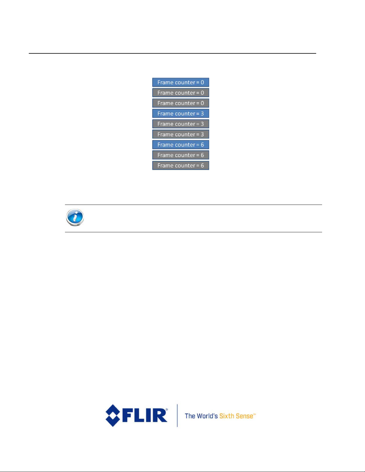
FLIR LEPTON® Engineering Datasheet
The information contained herein does not contain technology as defined by the EAR, 15 CFR 772, is publicly available,
and therefore, not subject to EAR. NSR (6/14/2018).
Information on this page is subject to change without notice.
Lepton Engineering Datasheet, Document Number: 500-0659-00-09 Rev: 203
51
Figure 25 - Frame Counter for Successive 80x60 Frames
NOTE: Blue frames are different than the previous frames, gray frames are identical
to the previous blue frame.
Page 52

FLIR LEPTON® Engineering Datasheet
The information contained herein does not contain technology as defined by the EAR, 15 CFR 772, is publicly available,
and therefore, not subject to EAR. NSR (6/14/2018).
Information on this page is subject to change without notice.
Lepton Engineering Datasheet, Document Number: 500-0659-00-09 Rev: 203
52
4.2.2.3.1 Establishing/Re-Establishing Sync
The basic process for establishing synchronization is listed below:
• Deassert /CS and idle SCK for at least 5 frame periods (>185 msec). This step ensures a timeout of the
VoSPI interface, which puts the Lepton in the proper state to establish (or re-establish) synchronization.
• Assert /CS and enable SCLK. This action causes the Lepton to start transmission of a first packet.
• Examine the ID field of the packet, identifying a discard packet. Read out the entire packet.
• Continue reading packets. When a new frame is available (should be less than 39 msec after asserting /CS
and reading the first packet), the first video packet will be transmitted. The master and slave are now
synchronized.
4.2.2.3.2 Maintaining Sync
There are three main violations that can result in a loss of synchronization:
• Intra-packet timeout. Once a packet starts, it must be completely clocked out within 3 line periods.
• Provided that VoSPI clock rate is appropriately selected and that /CS is not de-asserted (or SCLK
disrupted) during the packet transfer, an intra-packet timeout is an unexpected event.
• Failing to read out all packets for a given frame before the next frame is available. Two examples of this
violation are shown in Figure 27 and Figure 28. Note that the vertical blue line shown in the illustrations
represents an internal frame-sync signal that indicates a new frame is ready for read-out.
• Failing to read out all available frames. This violation is depicted in Figure 29. Note that the requirement
to read out all frames applies to both the unique and the duplicate frames.
A CRC error does not result in an automatic loss of synchronization. However, as mentioned previously, it is
recommended to intentionally re-synchronize (de-assert /CS for >185 msec) following a CRC error.
The following figures are examples of violations that result in a loss of synchronization.
Figure 26 - Valid Frame Timing (no loss of synchronization)
Page 53

FLIR LEPTON® Engineering Datasheet
The information contained herein does not contain technology as defined by the EAR, 15 CFR 772, is publicly available,
and therefore, not subject to EAR. NSR (6/14/2018).
Information on this page is subject to change without notice.
Lepton Engineering Datasheet, Document Number: 500-0659-00-09 Rev: 203
53
Figure 27 -Clock Too Slow - Failure to Read an Entire Frame Within the Frame Period
Figure 28 - Intra-Frame Delay Too Long - Failure to Read Out an Entire Frame Before the Next is
Available
Figure 29 - Failure to Read Out an Available Frame
4.2.2.3.3 Frame Synchronization
The VoSPI protocol is designed such that embedded timing signals are not required. However, the Lepton does
provide an optional frame-timing output pulse that can aid in optimizing host timing. For example, the host can
burst-read data at a high clock rate and then idle until the next frame-timing pulse is received. The pulse is enabled
by selecting the VSYNC GPIO mode via the CCI; when enabled, it is provided on the GPIO3 pin (see GPIO Modes,
page 39). The signal can be configured (also via the CCI) to lead or lag the actual internal start-of-frame (that is, the
time at which the next frame is ready to be read) by -3 to +3 line periods (approximately -1.5 msec to +1.5 msec).
By default, the pulse does not lead or lag.
Page 54

FLIR LEPTON® Engineering Datasheet
The information contained herein does not contain technology as defined by the EAR, 15 CFR 772, is publicly available,
and therefore, not subject to EAR. NSR (6/14/2018).
Information on this page is subject to change without notice.
Lepton Engineering Datasheet, Document Number: 500-0659-00-09 Rev: 203
54
4.2.3 VoSPI Protocol – Lepton 3.0 and 3.5
The Lepton 3 VoSPI is built on a collection of object types as defined hierarchically below.
▪ VoSPI Packet: The Lepton 3 VoSPI protocol is based on a single standardized VoSPI packet, the minimum
“transaction” between master and slave. Each video packet contains data for a single video line or
telemetry line. In addition to video packets, the VoSPI protocol includes discard packets that are provided
when no video packets are available.
▪ VoSPI Segment: A VoSPI segment is defined as a continuous sequence of VoSPI packets consisting of
one quarter of a frame of pixel data. To maintain synchronization, it is necessary to read out each
VoSPI segment before the next is available.
▪ VoSPI Stream: A VoSPI stream is defined as a continuous sequence of VoSPI segments.
As summarized in Table 10, the packet length and number of packets per frame vary depending upon two
runtime user selections, telemetry mode and bit resolution.
▪ Telemetry mode:
▪ Telemetry disabled (default)
▪ Telemetry enabled
▪ Video Format mode:
▪ Raw14 (default)
▪ RGB888
Table 12 - Packet Length and Number of Video Packets per Frame as a Function of User Settings
Video Format Mode
Telemetry Mode
Telemetry Disabled
Telemetry Enabled
Raw14
Packet length: 164 bytes
Video packets per frame: 60
Packet length: 164 bytes
Video packets per segment:
RGB888
Packet length: 244 bytes
Video packets per frame: 60
N/A
4.2.3.1 VoSPI Packets
As depicted in Figure 20, each packet contains a 4-byte header followed by either a 160-byte or 240-byte
payload. Note that because the payload size differs between video formats, the setting should be selected before
Page 55

FLIR LEPTON® Engineering Datasheet
The information contained herein does not contain technology as defined by the EAR, 15 CFR 772, is publicly available,
and therefore, not subject to EAR. NSR (6/14/2018).
Information on this page is subject to change without notice.
Lepton Engineering Datasheet, Document Number: 500-0659-00-09 Rev: 203
55
VoSPI synchronization is established. If the setting is changed while VoSPI is active, it is necessary to resynchronize (see VoSPI Stream, page 50).
Figure 30 - Generic VoSPI Packet
ID
CRC
Payload
4 bytes
160 or 240 bytes (depending upon bit resolution setting)
For video packets, the header includes a 2-byte ID and a 2-byte CRC. The ID field encodes the segment number
(1, 2, 3, or 4) and the packet number required to determine where the packet belongs in relation to the final 160
x 120 image (or 160x122 if telemetry is enabled). The segment and packet location in each frame is exemplified
in Figure 31. Recall that with telemetry disabled, each segment is comprised of 60 packets, each containing pixel
data for half of a video line. With telemetry enabled, each segment is comprised of 61 packets.
Figure 31 - Segment and Packet Relationship to the 160x120 video image
(a) Frame contents with telemetry disabled
Page 56

FLIR LEPTON® Engineering Datasheet
The information contained herein does not contain technology as defined by the EAR, 15 CFR 772, is publicly available,
and therefore, not subject to EAR. NSR (6/14/2018).
Information on this page is subject to change without notice.
Lepton Engineering Datasheet, Document Number: 500-0659-00-09 Rev: 203
56
(b) Frame contents with telemetry enabled
As shown in Figure 32, the first bit of the ID field is always a zero. The next three bits are referred to as the TTT
bits, and the following 12 are the packet number. Note that packet numbers restart at 0 on each new segment.
For all but packet number 20, the TTT bits can be ignored. On packet 20, the TTT bits encode the segment
number (1, 2, 3, or 4). The encoded segment number can also have a value of zero. In this case the entire
segment is invalid data and should be discarded. Figure 32 also shows an example of Packet 20 of Segment 3.
Figure 32 - Packet Header Encoding and an Example
(a) Generic Encoding of the packet header
Page 57

FLIR LEPTON® Engineering Datasheet
The information contained herein does not contain technology as defined by the EAR, 15 CFR 772, is publicly available,
and therefore, not subject to EAR. NSR (6/14/2018).
Information on this page is subject to change without notice.
Lepton Engineering Datasheet, Document Number: 500-0659-00-09 Rev: 203
57
(b) Example showing the packet header for line 20 of segment 3
The CRC portion of the packet header contains a 16-bit cyclic redundancy check (CRC), computed using the
following polynomial:
x
16
+ x
12
+ x5 + x
0
The CRC is calculated over the entire packet, including the ID and CRC fields. However, the four most-significant
bits of the ID and all sixteen bits of the CRC are set to zero for calculation of the CRC. There is no requirement for
the host to verify the CRC. However, if the host does find a CRC mismatch, it is recommended to re-synchronize the
VoSPI stream to prevent potential misalignment.
At the beginning of SPI video transmission until synchronization is achieved (see VoSPI Stream, page 50), and in
the idle period between frames, Lepton transmits discard packets until it has a new frame from its imaging
pipeline. As shown in Figure 22, the 2-byte ID field for discard packets is always xFxx (where 'x' signifies a “don't
care” condition). Note that VoSPI-enabled cameras do not have vertical resolution approaching 3840 lines
(0xF00), and therefore it is never possible for the ID field in a discard packet to be mistaken for a video line.
Figure 33 - Discard Packet
ID
CRC
Payload
xFxx
xxxx
Discard data (same number of bytes as video packets)
For video packets, the payload contents depend upon the selected bit resolution:
▪ For Raw14 mode (the default case), the payload is 160 bytes long. Excluding telemetry lines1, each packet
contains pixel data for all 80 pixels in a single video line (with AGC disabled, the first two bits of each
pixel's two-byte word are always set to 0; if AGC is enabled, the first eight bits are set to 0).
▪ For RGB888 mode, the payload is 240 bytes long. Excluding telemetry lines (which are invalid in RGB
mode), each packet consists of pixel data for a single video line (3 bytes per pixel).
Each case is illustrated in the following payload encoding figures.
Page 58

FLIR LEPTON® Engineering Datasheet
The information contained herein does not contain technology as defined by the EAR, 15 CFR 772, is publicly available,
and therefore, not subject to EAR. NSR (6/14/2018).
Information on this page is subject to change without notice.
Lepton Engineering Datasheet, Document Number: 500-0659-00-09 Rev: 203
58
Byte 0
Byte 1
Byte 2
Byte 3
Line m
Pixel 0
Line m
Pixel 1
Byte 158
Byte 159
Line m
Pixel 79
Byte 0
Byte 1
Byte 2
Byte 3
Byte 4
Byte 5
Line m
Pixel 0
R
Line m
Pixel 0
G
Line m
Pixel 0
B
Line m
Pixel 1
R
Line m
Pixel 1
G
Line m
Pixel 1
B
Byte 237
Byte 238
Byte 239
Line m
Pixel 79
R
Line m
Pixel 79
G
Line m
Pixel 79
B
Figure 34 - Raw14 Mode: 1 video line per 160-byte payload
...
...
Figure 35 - RGB888 Mode: 1 video line per 240-byte payload
...
Note(s)
1. See Telemetry Modes, page 23 for payload contents of the telemetry lines
4.2.3.2 VoSPI Segments
Each valid Lepton 3 segment contains data for one quarter of a complete frame. With telemetry disabled, each
segment includes 60 packets comprising 30 video rows. When telemetry is enabled, each segment includes 61 packets
comprising 30.5 rows. Note that with telemetry enabled, two rows (4 packets) of pixel data is replaced by the telemetry
lines; pixel data is either shifted down in which the bottom two rows are excluded (header mode) or up in which the top
two rows are excluded (footer mode). With telemetry enabled as a header, packets 0 -3 of segment 1 provide the
telemetry data and the remaining 57 packets of segment 1 provide data for the first 28.5 rows of pixel data. Segments
2, 3, and 4 each provide data for 30.5 rows of pixel data. When telemetry is enabled as a footer, segments 1, 2, and 3
each provide data for 3.05 rows of pixel data whereas packets 0 – 56 of segment 4 contain 28.5 rows of pixel data, and
packets 57 – 60 provide the telemetry data. The location of the telemetry lines is illustrated in Figure 36.
Figure 36 - Location of Telemetry Lines
Page 59

FLIR LEPTON® Engineering Datasheet
The information contained herein does not contain technology as defined by the EAR, 15 CFR 772, is publicly available,
and therefore, not subject to EAR. NSR (6/14/2018).
Information on this page is subject to change without notice.
Lepton Engineering Datasheet, Document Number: 500-0659-00-09 Rev: 203
59
(a) Telemetry as header
(b) Telemetry as footer
4.2.3.3 VoSPI Stream
A VoSPI stream is simply a continuous sequence of VoSPI segments following a synchronization event. Provided that
synchronization is maintained, a VoSPI stream can continue indefinitely. The segment rate is approximately 106 Hz,
which equates to a frame rate of ~ 26.5 Hz. However, the rate of unique and valid frames is just below 9 Hz to comply
Page 60

FLIR LEPTON® Engineering Datasheet
The information contained herein does not contain technology as defined by the EAR, 15 CFR 772, is publicly available,
and therefore, not subject to EAR. NSR (6/14/2018).
Information on this page is subject to change without notice.
Lepton Engineering Datasheet, Document Number: 500-0659-00-09 Rev: 203
60
with US export restrictions. For each unique frame, two partial and invalid frames follow in the VoSPI stream. This
pattern is illustrated in Figure 37, with unique frames shown in blue and invalid frames shown in gray. The 32-bit
frame counter provided in the telemetry lines (see Telemetry Modes, page 23) only increments on new frames,
which is also illustrated in Figure 37. The segment numbers will follow accordingly: 1, 2, 3, 4, 0, 0, 0, 0, 0, 0, 0, 0,
1, 2, 3, 4, etc., where unique frames are comprised of segment numbers 1, 2, 3, 4 and invalid frames are
comprised of zeros for each segment number.
Figure 37 - Frame Counter for Successive Frames
NOTE: Blue frames are different than the previous frames, gray frames are invalid.
4.2.3.3.1 Establishing/Re-Establishing Sync
The basic process for establishing synchronization is listed below:
• Deassert /CS and idle SCK for at least 5 frame periods (>185 msec). This step ensures a timeout of
the
VoSPI interface, which puts the Lepton 3 in the proper state to establish (or re-establish) synchronization.
• Assert /CS and enable SCLK. This action causes the Lepton 3 to start transmission of a first packet.
• Examine the ID field of the packet, identifying a discard packet. Read out the entire packet.
Page 61

FLIR LEPTON® Engineering Datasheet
The information contained herein does not contain technology as defined by the EAR, 15 CFR 772, is publicly available,
and therefore, not subject to EAR. NSR (6/14/2018).
Information on this page is subject to change without notice.
Lepton Engineering Datasheet, Document Number: 500-0659-00-09 Rev: 203
61
• Continue reading packets. When a new segment is available (should be less than 10 msec after asserting /CS
and reading the first packet), the first video packet will be transmitted. The master and slave are now
synchronized.
4.2.3.3.2 Maintaining Sync
There are three main violations that can result in a loss of synchronization:
▪ Intra-packet timeout. Once a packet starts, it must be completely clocked out within 3 line periods.
▪ Provided that VoSPI clock rate is appropriately selected and that /CS is not de-asserted (or SCLK
disrupted) in the midst of the packet transfer, an intra-packet timeout is an unexpected event.
▪ Failing to read out all packets for a given frame before the next frame is available. Two examples of this
violation are shown in Figure 27 and Figure 28. Note that the vertical blue line shown in the illustrations
represents an internal frame-sync signal that indicates a new frame is ready for read-out.
▪ Failing to read out all available frames. This violation is depicted in Figure 29. Note that the requirement
to read out all frames applies to both the unique and the duplicate frames.
A CRC error does not result in an automatic loss of synchronization. However, as mentioned previously, it is
recommended to intentionally re-synchronize (de-assert /CS for >185 msec) following a CRC error.
The following figures are examples of violations that result in a loss of synchronization.
Figure 38 - Valid Frame Timing (no loss of synchronization)
Figure 39 - Clock Too Slow - Failure to Read an Entire Frame Within the Frame Period
Page 62

FLIR LEPTON® Engineering Datasheet
The information contained herein does not contain technology as defined by the EAR, 15 CFR 772, is publicly available,
and therefore, not subject to EAR. NSR (6/14/2018).
Information on this page is subject to change without notice.
Lepton Engineering Datasheet, Document Number: 500-0659-00-09 Rev: 203
62
Figure 40 - Intraframe Delay Too Long - Failure to Read Out an Entire Frame Before the Next is
Available
Figure 41 - Failure to Read Out an Available Frame
4.2.3.3.3 Frame Synchronization
The VoSPI protocol is designed such that embedded timing signals are not required. However, Lepton
3
does
provide an optional frame-timing output pulse that can aid in optimizing host timing. For example, the host can
burst-read data at a high clock rate and then idle until the next frame-timing pulse is received. The pulse is enabled
by selecting the VSYNC GPIO mode via the CCI; when enabled, it is provided on the GPIO3 pin (see GPIO Modes,
page 39). The signal can be configured (also via the CCI) to lead or lag the actual
internal start-of-frame (that is,
the time at which the next frame is ready to be read) by -3 to +3 line periods (approximately -1.5 msec to +1.5
msec). By default, the pulse does not lead or lag.
4.2.4 VoSPI Protocol – Lepton 2 vs. Lepton 3
This section is provided for customers already familiar with the Lepton VoSPI protocol. It concisely summarizes
the difference between Lepton (80x60 resolution) and Lepton 3 (160x120 resolution). Much of the protocol is
identical, including the following:
1) The physical layer is identical, including the SPI mode and timing.
2) The minimum VoSPI transaction is a packet, consisting of 164 bytes of data when in Raw14 video mode or
244 bytes of data when in RGB888 mode. The packet protocol, including the packet header and payload,
Page 63

FLIR LEPTON® Engineering Datasheet
The information contained herein does not contain technology as defined by the EAR, 15 CFR 772, is publicly available,
and therefore, not subject to EAR. NSR (6/14/2018).
Information on this page is subject to change without notice.
Lepton Engineering Datasheet, Document Number: 500-0659-00-09 Rev: 203
63
are unchanged. However, it is worth noting a single packet represented a single 80-pixel video line for
Lepton whereas it represents half of a 160-pixel video line in Lepton 3.
3) The synchronization requirements are identical with one exception. To maintain synchronization, Lepton
requires each video frame to be read out prior to the next available frame. In contrast, Lepton 3 requires
each segment to be read out prior to the next available segment, where a segment represents onequarter of a video frame. Lepton 3 sync pulse cannot be used to synchronize external circuitry to frames.
4) For both Lepton and Lepton 3, each unique video frame is followed by two non-unique frames which
must be read out to maintain synchronization. For Lepton each unique video frame is duplicated twice.
For Lepton 3 each unique frame is followed by two partial, invalid frames.
The four most significant differences between the Lepton VoSPI interface and that for Lepton 3 are:
1) For Lepton, reconstructing a video frame from the individual packets requires the host to decode the
packet number from each packet header. For Lepton 3, the host must decode both the packet number
and the segment number.
2) There is 4X more data to be read per frame on Lepton 3 compared to Lepton. Therefore, the minimum
SPI clock rate to read a frame of data is 4X higher.
3) If the sync pulse is enabled (see section 9.2.3), its frequency is 4X higher on Lepton 3 than on Lepton. For
Lepton 3, the sync pulse represents when the next available segment is available whereas for Lepton it
indicates when the next available frame is available.
When telemetry is enabled in Lepton, it results in three extra video lines (63 total packets per frame). When
telemetry is enabled in Lepton 3, it results in 1 additional packet per segment for a total of 2 extra video lines.
5 Thermal Camera Basics
It is noteworthy that the integration period for a thermal detector does not have the same impact on image
formation as it does for a photon detector, such as a typical CMOS array. While a photon detector converts incoming
photons to electrons with near-instantaneous response a microbolometer, such as the Lepton, is always integrating
incident radiation. That is to say, it is always “active” regardless of whether or not it is being actively integrated.
The ability to detect high-speed phenomena is more a function of the detector's thermal time constant, which
governs the rate of temperature change. For Lepton, the detector time constant is on the order of 12 msec, which
means that an instantaneous irradiance change will result in a temperature change of the detector as shown in
Figure 42.
Page 64

FLIR LEPTON® Engineering Datasheet
The information contained herein does not contain technology as defined by the EAR, 15 CFR 772, is publicly available,
and therefore, not subject to EAR. NSR (6/14/2018).
Information on this page is subject to change without notice.
Lepton Engineering Datasheet, Document Number: 500-0659-00-09 Rev: 203
64
Figure 42 - Illustration of Lepton Detector Time Constant
In addition to integrating signal current, the ROIC also digitizes and multiplexes the signal from each detector into
a serial stream. And the Lepton ROIC digitizes data from an on-chip temperature sensor as well as a thermistor
attached to the camera housing. An anti-reflection (AR) coated window is bonded above the sensor array via a
wafer-level packaging (WLP) process, encapsulating the array in a vacuum. The purpose of the vacuum is to
provide high thermal resistance between the microbolometer elements and the ROIC substrate, allowing for
maximum temperature change in response to incident radiation.
Page 65

FLIR LEPTON® Engineering Datasheet
The information contained herein does not contain technology as defined by the EAR, 15 CFR 772, is publicly available,
and therefore, not subject to EAR. NSR (6/14/2018).
Information on this page is subject to change without notice.
Lepton Engineering Datasheet, Document Number: 500-0659-00-09 Rev: 203
65
6 Mounting Specifications
The Lepton camera mechanical interface is defined in the drawings in section References on page 6. An example with
socket is shown in Figure 43.
Figure 43 - Lepton with Radiometry Camera Mounting Dimensions
Page 66

FLIR LEPTON® Engineering Datasheet
The information contained herein does not contain technology as defined by the EAR, 15 CFR 772, is publicly available,
and therefore, not subject to EAR. NSR (6/14/2018).
Information on this page is subject to change without notice.
Lepton Engineering Datasheet, Document Number: 500-0659-00-09 Rev: 203
66
6.1 Socket Information
The Lepton module is compatible with two commercially-available sockets, Molex 105028-1001 and Molex
105028-2031, illustrated in Figure 44 below. The former makes electrical contact on the upper surface of a
printed circuit board, the latter to the lower surface (with a cutout in the board that allows the socket to fit into).
In both cases solder connections are made to the top or “component” side of the board. Figure 45 depicts both
socket configurations mounted on a PCB.
To order sockets, visit www.arrow.com.
Figure 44 - Two Commercially-available Sockets (both from Molex) Compatible with Lepton
Page 67

FLIR LEPTON® Engineering Datasheet
The information contained herein does not contain technology as defined by the EAR, 15 CFR 772, is publicly available,
and therefore, not subject to EAR. NSR (6/14/2018).
Information on this page is subject to change without notice.
Lepton Engineering Datasheet, Document Number: 500-0659-00-09 Rev: 203
67
Figure 45 - Both Sockets Mounted on a PCB
Page 68

FLIR LEPTON® Engineering Datasheet
The information contained herein does not contain technology as defined by the EAR, 15 CFR 772, is publicly available,
and therefore, not subject to EAR. NSR (6/14/2018).
Information on this page is subject to change without notice.
Lepton Engineering Datasheet, Document Number: 500-0659-00-09 Rev: 203
68
6.2 Mechanical Considerations
The socket described in Socket Information on page 66 is not intended to retain the Lepton assembly under
high-shock conditions. It is recommended to incorporate front-side retention such as illustrated in Figure 46. Note
that a maximum, uniform, load of 1kgF can be applied to the shutter face without causing failures in shutter
actuation. When designing the foam thickness and compression the tolerances have to be such that the
maximum force of 1kgF at the same time as enough force is exerted to keep the Lepton in the socket.
Figure 46 - Recommended Approach to Retaining Lepton in the end Application
The Lepton camera is not a sealed assembly. Consequently, for most applications it is recommended to locate the
assembly behind a sealed protective window. Common materials for LWIR windows include silicon, germanium,
and zinc selenide (LWIR absorption in silicon is on the order of 15%/mm, which means NEDT is adversely affected
using a silicon window. Bulk absorption in germanium and zinc selenide is negligible, and performance is
essentially unchanged provided both surfaces of the window are anti-reflection (AR) coated.) Note that the
window should be sized large enough to avoid encroaching upon the optical keep-out zone (see Optical
Considerations, page 69).
Page 69

FLIR LEPTON® Engineering Datasheet
The information contained herein does not contain technology as defined by the EAR, 15 CFR 772, is publicly available,
and therefore, not subject to EAR. NSR (6/14/2018).
Information on this page is subject to change without notice.
Lepton Engineering Datasheet, Document Number: 500-0659-00-09 Rev: 203
69
6.3 Thermal Considerations
It is important to minimize any temperature gradient across the camera. The sensor should be mounted in such a
fashion so as to isolate it from heat loads such as electronics, heaters, and non-symmetric external heating. The
surrounding area must be able to support and withstand the dissipation of up to 160 mW of heat by the camera.
6.4 Optical Considerations
The optical keep-out zone is described by the three-dimensional field of view cone within the Lepton with
Radiometry STEP file. To avoid mechanical vignetting, do not impinge upon the keep-out zone defined by this
cone.
7 Image Characteristics
The information given in Table 13 applies across the full operating temperature range.
Table 13 - Image Characteristics
Parameter
Description
Value
NETD
Noise Equivalent Temperature Difference (random
temporal noise)
<50 mK, radiometry mode
(35 mK typical)
Intra-scene
Range
Minimum and maximum scene temperature
High Gain Mode: -10°C to
140°C, typical1
Low Gain Mode: -10°C to
450°C, typical1
Operability
Number of non-defective pixels
>99.0%
Clusters
Number of adjacent defective pixels
“Adjacent” means any of the 8 nearest neighbors (or
nearest 5 for an edge pixel, nearest 3 for a corner).
No clusters allowed.
Note(s)
1. Scene dynamic range is a function of sensor characteristics and ambient temperature. Range values reported are typical values at
room temperature ambient. See Table 1- Key Specifications for details.
2. Only single-pixel defects are allowed (no clusters).
Page 70

FLIR LEPTON® Engineering Datasheet
The information contained herein does not contain technology as defined by the EAR, 15 CFR 772, is publicly available,
and therefore, not subject to EAR. NSR (6/14/2018).
Information on this page is subject to change without notice.
Lepton Engineering Datasheet, Document Number: 500-0659-00-09 Rev: 203
70
The nominal minimum on-axis modulation transfer function (MTF) at Nyquist/2 for the Lepton lens assembly is 63%
for Lepton 1.5, 1.6, 2.0 and 2.5, and 51% for Lepton 3.0 and 3.5.
Page 71

FLIR LEPTON® Engineering Datasheet
The information contained herein does not contain technology as defined by the EAR, 15 CFR 772, is publicly available,
and therefore, not subject to EAR. NSR (6/14/2018).
Information on this page is subject to change without notice.
Lepton Engineering Datasheet, Document Number: 500-0659-00-09 Rev: 203
71
8 Spectral Response
For reference, Figure 47 depicts the typical spectral response of the Lepton camera.
Figure 47 - Normalized Response as a Function of Signal Wavelength for Lepton 1.5, 2.0 and 2.5
Page 72

FLIR LEPTON® Engineering Datasheet
The information contained herein does not contain technology as defined by the EAR, 15 CFR 772, is publicly available,
and therefore, not subject to EAR. NSR (6/14/2018).
Information on this page is subject to change without notice.
Lepton Engineering Datasheet, Document Number: 500-0659-00-09 Rev: 203
72
Figure 48 - Normalized Response as a Function of Signal Wavelength for Lepton 3.0 and 3.5
0%
10%
20%
30%
40%
50%
60%
70%
80%
90%
100%
6.0 7.0 8.0 9.0 10.0 11.0 12.0 13.0 14.0 15.0
Normalized Response
Wavelength (micron)
Normalized Response
Page 73

FLIR LEPTON® Engineering Datasheet
The information contained herein does not contain technology as defined by the EAR, 15 CFR 772, is publicly available,
and therefore, not subject to EAR. NSR (6/14/2018).
Information on this page is subject to change without notice.
Lepton Engineering Datasheet, Document Number: 500-0659-00-09 Rev: 203
73
9 Electrical Specifications
9.1 Lepton pin-out
Figure 49 - Pinout Diagram (viewed from bottom of camera module)
Page 74

FLIR LEPTON® Engineering Datasheet
The information contained herein does not contain technology as defined by the EAR, 15 CFR 772, is publicly available,
and therefore, not subject to EAR. NSR (6/14/2018).
Information on this page is subject to change without notice.
Lepton Engineering Datasheet, Document Number: 500-0659-00-09 Rev: 203
74
Table 14 - Lepton Camera Module Pin Descriptions
Pin #
Pin Name
Signal
Type
Signal Level
Description
1, 6, 8,
9, 10,
15, 18,
20, 25,
27, 30
GND
Power
GND
Common Ground
2
GPIO3/VSYNC
IN/OUT
VDDIO
Video output synchronization (see GPIO
Modes page 39)
3
GPIO2
IN/OUT
VDDIO
Reserved
4
GPIO1
IN/OUT
VDDIO
Reserved
5
GPIO0
IN/OUT
VDDIO
Reserved
7
VDDC
Power
1.2V
Supply for MIPI Core, PLL, ASIC Core (1.2V
+/- 5%)
11
SPI_MOSI
IN
VDDIO
Video Over SPI Slave Data In (see VoSPI
Channel page 44)
12
SPI_MISO
OUT
VDDIO
Video Over SPI Slave Data Out (see VoSPI
Channel page 44)
13
SPI_CLK
IN
VDDIO
Video Over SPI Slave Clock (see VoSPI
Channel page 44)
14
SPI_CS_L
IN
VDDIO
Video Over SPI Slave Chip Select, active low
(see VoSPI Channel page 44)
Page 75

FLIR LEPTON® Engineering Datasheet
The information contained herein does not contain technology as defined by the EAR, 15 CFR 772, is publicly available,
and therefore, not subject to EAR. NSR (6/14/2018).
Information on this page is subject to change without notice.
Lepton Engineering Datasheet, Document Number: 500-0659-00-09 Rev: 203
75
Table 15 - Lepton Camera Module Pin Descriptions (cont.)
Pin #
Pin Name
Signal
Type
Signal Level
Description
16
VDDIO
Power
2.8 V — 3.1 V
Supply used for System IO
17
VPROG
— — See section 2.8.
19
VDD
Power
2.8V
Supply for Sensor (2.8V +/- 3%).
21
SCL
IN
VDDIO
Camera Control Interface Clock, I2C
compatible
(see Command and Control
Interface, page 40)
22
SDA
IN/OUT
VDDIO
Camera Control Interface Data, I2C
compatible
(see Command and Control
Interface, page 40)
23
PWR_DWN_L
IN
VDDIO
This active low signal shuts down the camera
24
RESET_L
IN
VDDIO
This active low signal resets the camera
26
MASTER_CLK
IN
VDDIO
ASIC Master Clock Input (see Master Clock,
page 15)
28
RESERVED
29
RESERVED
31
RESERVED
32
RESERVED
Page 76

FLIR LEPTON® Engineering Datasheet
The information contained herein does not contain technology as defined by the EAR, 15 CFR 772, is publicly available,
and therefore, not subject to EAR. NSR (6/14/2018).
Information on this page is subject to change without notice.
Lepton Engineering Datasheet, Document Number: 500-0659-00-09 Rev: 203
76
9.2 DC and Logic Level Specifications
Table 16 - DC and Logic Levels
Symbol
Parameter
Min
Typ
Max
Units
VDDC
Core Voltage (primary power for
the Lepton internal ASIC)
1.14
1.20
1.26
Volts
VDDCpp
VDDC, peak-to-peak ripple voltage
— — 50
mV
VDD
Sensor Voltage (primary power
for the Lepton internal sensor
2.72
2.80
2.88
Volts
VDDpp
VDD, peak-to-peak ripple voltage
— — 30
mV
VDDIO
3
I/O Voltage (primary power for
the Lepton I/O ring)
2.8
—
3.1
Volts
VDDIOpp
VDDIO, peak-to-peak ripple
voltage
—
—
50
mV
I_DDC
Supply current for core (VDDC)
76
84
110
mA
I_DD
Supply current for sensor (VDD)
12
14
16
1
mA
I_DDIO
Supply current for I/O ring
and shutter assembly (VDDIO)
1
235 mA
(during FFC)
310 mA
2
(during FFC)
mA
Note(s)
1. Maximum measured at 65 degrees C
2. Maximum at -10 degrees C
3. FLIR recommends utilizing two separate power supplies rather than a common supply for VDD and VDDIO due to noise
considerations.
Page 77

FLIR LEPTON® Engineering Datasheet
The information contained herein does not contain technology as defined by the EAR, 15 CFR 772, is publicly available,
and therefore, not subject to EAR. NSR (6/14/2018).
Information on this page is subject to change without notice.
Lepton Engineering Datasheet, Document Number: 500-0659-00-09 Rev: 203
77
9.3 AC Electrical Characteristics
Table 17 - AC Electrical Characteristics
Parameter
Min
Typ
Max
Units
MASTER_CLK, F
clk
24.975 MHz
See note 1
25 MHz
25.025 MHz
See note 1, 2
Master clock
rate
MASTER_CLK, F
clk duty
45%
50%
55%
Master clock
duty cycle
MASTER_CLK, tr
--
--
3.4ns
Clock rise time
(10% to 90%)
MASTER_CLK, tf
--
--
3.4ns
Clock fall time
(90% to 10%)
SPI_CLK, F
clk
See note 3
20 MHz
VoSPI clock rate
SPI_CLK, F
clk duty
45%
50%
55%
SPI-clock duty
cycle
SPI_CLK, tr
--
--
TBD
SPI clock rise time
(10% to 90%)
SPI_CLK, tf
--
--
TBD
SPI clock fall time
(90% to 10%)
SCL, F
clk
1 MHz
I2C clock rate
SCL, F
clk duty
45%
50%
55%
I2C-clock duty
cycle
SCL_CLK, tr
--
--
TBD
I2C clock rise time
(10% to 90%)
SCL_CLK, tf
--
--
TBD
I2C clock fall time
(90% to 10%)
Note(s)
1. Master clock frequencies significantly more or less than 25MHz may cause image degradation.
2. Master clock frequencies significantly above 25.5MHz will cause the camera to stop displaying live sensor data and display an
overclock test pattern.
3. As described in VoSPI Protocol, page 46, the minimum VoSPI clock frequency is dependent upon the requirement to read
out all video packets for a given frame within the frame period. The size and number of video packets vary with user
settings.
Page 78

FLIR LEPTON® Engineering Datasheet
The information contained herein does not contain technology as defined by the EAR, 15 CFR 772, is publicly available,
and therefore, not subject to EAR. NSR (6/14/2018).
Information on this page is subject to change without notice.
Lepton Engineering Datasheet, Document Number: 500-0659-00-09 Rev: 203
78
9.4 Absolute Maximum Ratings
Electrical stresses beyond those listed in Table 18 may cause permanent damage to the device. These are stress
rating only, and functional operation of the device at these or any other conditions beyond those indicated under
the recommended operating conditions listed in Table 19 is not implied. Exposure to absolute-maximum-rated
conditions for extended periods of time may affect device reliability.
Table 18 - Absolute Maximum Ratings
Parameter
Absolute Maximum Rating
Core Voltage (VDDC)
1.5 V
Sensor Voltage (VDD)
4.8 V
I/O Voltage (VDDIO)
4.8 V
Voltage on any I/O pin
Lesser of (VDDIO + 0.6V) or
4.8V
9.5 Electronic integration considerations
A typical example of integrating a Lepton on a PCB is shown in Figure 50. Matching Cadence design files can be
found in References, page 6. The MOSI signal is not used and can be grounded.
Figure 50. Example of Lepton schematic.
Page 79

FLIR LEPTON® Engineering Datasheet
The information contained herein does not contain technology as defined by the EAR, 15 CFR 772, is publicly available,
and therefore, not subject to EAR. NSR (6/14/2018).
Information on this page is subject to change without notice.
Lepton Engineering Datasheet, Document Number: 500-0659-00-09 Rev: 203
79
10 Environmental Specifications
Page 80

FLIR LEPTON® Engineering Datasheet
The information contained herein does not contain technology as defined by the EAR, 15 CFR 772, is publicly available,
and therefore, not subject to EAR. NSR (6/14/2018).
Information on this page is subject to change without notice.
Lepton Engineering Datasheet, Document Number: 500-0659-00-09 Rev: 203
80
Environmental stresses beyond those listed may cause permanent damage to the device. Exposure to absolutemaximum-rated conditions for extended periods of time may affect device reliability.
Table 19 - Environmental Specifications
Stress
Maximum Rating
Operating Temperature Range
-10°C to 80°C
(-20°C to 80°C with some possible performance degradation)
Maximum Operating Temperature
80 °C1
Shutter Operating Temperature
-10°C to 80°C2
Storage Temperature
-40°C to 80°C
Altitude (pressure)
12 km altitude equivalent
Relative Humidity
95%
Thermal Shock
Air-to-air across operating temp. extremes (-10°C to 65°C,
65°C to -10°C)
Mechanical Shock
1500 g, 0.4 msec
Vibration
Transportation profile, 4.3 grms
ESD
Human Body Model (HBM), 2kV
Charged Device Model (CDM), 500V
Note(s)
1. Lepton contains an automatic shutdown feature when its internal temperature exceeds the maximum safe operating value.
See Power States, page 15.
2. Lepton contains an automatic shutter lockout feature that prevents the shutter from operating when its internal temperature
is outside the range of -10°C to 80°C for Lepton 2.5 and 3.5, and -10°C to 65°C for Lepton 2.0 and 3.0. See FFC States,
page 18.
10.1 Compliance with Environmental Directives
Lepton complies with the following directives and regulations:
• Directive 2002/95/EC, “Restriction of the use of certain Hazardous Substances in electrical and electronic
equipment (RoHS)”
• Directive 2002/96/ EC, “Waste Electrical and Electronic Equipment (WEEE)”.
• Regulation (EC) 1907/2006, “Registration, Evaluation, Authorization and Restriction of Chemicals
(REACH)”
Page 81

FLIR LEPTON® Engineering Datasheet
The information contained herein does not contain technology as defined by the EAR, 15 CFR 772, is publicly available,
and therefore, not subject to EAR. NSR (6/14/2018).
Information on this page is subject to change without notice.
Lepton Engineering Datasheet, Document Number: 500-0659-00-09 Rev: 203
81
Page 82

FLIR LEPTON® Engineering Datasheet
The information contained herein does not contain technology as defined by the EAR, 15 CFR 772, is publicly available,
and therefore, not subject to EAR. NSR (6/14/2018).
Information on this page is subject to change without notice.
Lepton Engineering Datasheet, Document Number: 500-0659-00-09 Rev: 203
82
11 Abbreviations and Acronyms
Abbreviation
Description
AGC
Automatic Gain Control
AR
Anti-reflection
CCI
Command and Control Interface
CRC
Cyclic Redundancy Check
DSP
Digital Signal Processor
EMC
Electromagnetic Compatibility
FFC
Flat Field Correction
FOV
Field of View
FPA
Focal Plane Array
FPN
Fixed Pattern Noise
GPIO
General Purpose IO
HFOV
Horizontal Field of View
I2C
Inter-Integrated Circuit
IDD
Interface Description Document
LWIR
Long Wave Infrared
MISO
Maser In/Slave Out
MOSI
Master Out/Slave In
NEDT
Noise Equivalent Differential Temperature
NUC
Non-Uniformity Correction
OTP
One-Time Programmable
PLL
Phase-Lock Loop
REACH
Registration, Evaluation, Authorization, and Restriction of Chemicals
Page 83

FLIR LEPTON® Engineering Datasheet
The information contained herein does not contain technology as defined by the EAR, 15 CFR 772, is publicly available,
and therefore, not subject to EAR. NSR (6/14/2018).
Information on this page is subject to change without notice.
Lepton Engineering Datasheet, Document Number: 500-0659-00-09 Rev: 203
83
RoHS
Reduction of Hazardous Substances
ROIC
Readout Integrated Circuit
SBNUC
Scene-based Non-uniformity Correction
SNR
Signal to Noise Ratio
SoC
System on a Chip
SPI
Serial Peripheral Interface
SVP
Software-based Video Processing
TCR
Temperature Coefficient of Resistance
TWI
Two-wire Interface
VoSPI
Video Over SPI
VOx
Vanadium-oxide
WEEE
Waste Electrical and Electronic Equipment
WLP
Wafer-level Packaging
Page 84

FLIR LEPTON® Engineering Datasheet
The information contained herein does not contain technology as defined by the EAR, 15 CFR 772, is publicly available,
and therefore, not subject to EAR. NSR (6/14/2018).
Information on this page is subject to change without notice.
Lepton Engineering Datasheet, Document Number: 500-0659-00-09 Rev: 203
84
© FLIR Commercial Systems,
2014.
All rights reserved worldwide. No parts of this manual, in whole or in part, may be
copied, photocopied, translated, or transmitted to any electronic medium or machine readable form without the prior written
permission of FLIR Commercial Systems
Names and marks appearing on the products herein are either registered trademarks or trademarks of FLIR Commercial Systems
and/or its subsidiaries. All other trademarks, trade names or company names referenced herein are used for identification only and
a r e the property of their respective owners.
This product is protected by patents, design patents, patents pending, or design patents pending.
If you have questions that are not covered in this manual, or need service, contact FLIR Commercial Systems Customer Support
at 805.964.9797 for additional information prior to returning a camera.
This documentation and the requirements specified herein are subject to change without notice.
This equipment must be disposed of as electronic waste.
Contact your nearest FLIR Commercial Systems, Inc. representative for instructions on how to return the product to
FLIR for proper disposal.
FCC Notice. This device is a subassembly designed for incorporation into other products in order to provide an infrared camera function. It is not an
end-product fit fo1r consumer use. When incorporated into a host device, the end-product will generate, use, and radiate radio frequency energy that
may cause radio interference. As such, the end-product incorporating this subassembly must be tested and approved under the rules of the Federal
Communications Commission (FCC) before the end-product may be offered for sale or lease, advertised, imported, sold, or leased in the United
States. The FCC regulations are designed to provide reasonable protection against interference to radio communications. See 47 C.F.R. §§ 2.803
and 15.1 et seq.
Industry Canada Notice. This device is a subassembly designed for incorporation into other products in order to provide an infrared camera
function. It is not an end-product fit for consumer use. When incorporated into a host device, the end-product will generate, use, and radiate radio
frequency energy that may cause radio interference. As such, the end-product incorporating this subassembly must be tested for compliance with
the Interference-Causing Equipment Standard, Digital Apparatus, ICES-003, of Industry Canada before the product incorporating this device may
be: manufactured or offered for sale or lease, imported, distributed, sold, or leased in Canada.
Avis d’Industrie Canada. Cet appareil est un sous-ensemble conçu pour être intégré à un autre produit afin de fournir une fonction de caméra
infrarouge. Ce n’est pas un produit final destiné aux consommateurs. Une fois intégré à un dispositif hôte, le produit final va générer, utiliser et
émettre de l’énergie radiofréquence qui pourrait provoquer de l’interférence radio. En tant que tel, le produit final intégrant ce sous-ensemble doit
être testé pour en vérifier la conformité avec la Norme sur le matériel brouilleur pour les appareils numériques (NMB-003) d’Industrie Canada avant
que le produit intégrant ce dispositif puisse être fabriqué, mis en vente ou en location, importé, distribué, vendu ou loué au Canada.
EU Notice. This device is a subassembly or component intended only for product evaluation, development or incorporation into other products in
order to provide an infrared camera function. It is not a finished end-product fit for general consumer use. Persons handling this device must have
appropriate electronics training and observe good engineering practice standards. As such, this product does not fall within the scope of the
European Union (EU) directives regarding electromagnetic compatibility (EMC). Any end-product intended for general consumer use that
incorporates this device must be tested in accordance and comply with all applicable EU EMC and other relevant directives.
 Loading...