

Page 1

User’s manual
FLIR Kx3 series
Page 2

Page 3

User’s manual
FLIR Kx3 series
#T810170; r. AE/41948/41948; en-US
iii
Page 4

Page 5

Table of contents
1 Legal disclaimer ....... ....... ....... .......................... ....... ....... .....................1
1.1 Legal disclaimer .... ....... ............ ....... ....... ....... ....... ....... ..... ....... ... 1
1.2 Usage statistics .................... ....... ....... ....... ....... ....... ..... ....... ....... 1
1.3 Changes to registry ............. ....... ....... ....... .......................... ....... ..1
1.4 U.S. Government Regulations.......................... ....... ....... ................1
1.5 Copyright . ....... .......................... ....... ....... .......................... ....... . 1
1.6 Quality assurance ......... ....... ....... .......................... ....... ....... ....... . 1
1.7 Patents.... ....... ....... ....... ....... ....... .......................... ....... ....... ...... 1
1.8 EULA Terms ............... ....... ....... .......................... ....... ....... .........1
2 Safety information .... ....... ....... ....... ................... ....... ....... ....... ..............2
3 Notice to user .. ....... ....... .......................... ....... ....... ................... ....... ... 6
3.1 User-to-user forums ..... .......................... ....... ....... .......................6
3.2 Disposal of electronic waste . .......................... ....... ....... ................. 6
3.3 Training ..... ..... ....... ....... ....... ....... ....... .......................... ....... ...... 6
3.4 Documentation updates .... .......................... ....... ....... ....... ............ 6
3.5 Important note about this manual.. ....... ....... ....... ....... ..... .. ..... ....... ... 6
3.6 Note about authoritative versions.... .......................... ....... ....... ....... . 7
4 Customer help ................................. ....... ....... .......................... ....... ....8
4.1 General ..... ....... ....... ....... ..... ....... ....... ....... ....... ....... ............ ...... 8
4.2 Submitting a question .......................... ....... ....... ....... ....... ............ 8
4.3 Downloads ............... ....... ....... ....... ....... ............ ....... ....... ....... ....9
5 Important information about FLIR Kx3 series service..... ....... ....... .......... 10
6 Quick start guide ..... ....... ................... ....... ....... ....... ................... ....... . 11
6.1 Quick start guide, FLIR K33 ....... ....... ....... .......................... ....... .. 11
6.2 Quick start guide, FLIR K53 ....... ....... ....... .......................... ....... .. 11
7 List of accessories and services ........... ........................................ ...... 12
8 System configuration overview ............................ ....... ....... ....... .......... 13
8.1 Figure .. ....... .......................... ....... ....... .......................... ....... .. 13
8.2 Explanation ..... ....... ....... .......................... ....... ....... .................. 13
9 System parts..... ....... ................... ....... ....... ....... ................................. 15
9.1 Camera parts ... ....... ....... .......................... ....... ....... .................. 15
9.1.1 Figure.... ....... ....... ..... ....... ....... ....... ....... ....... ............ .... 15
9.1.2 Explanation..... ....... .......................... ....... ....... ............... 15
9.2 Lanyard strap and retractable lanyard............... ....... ....... ....... ........ 16
9.3 Handle strap and retractable lanyard. ....... .......................... ....... .... 16
9.4 Neck strap... ....... ....... ....... ....... ................... ....... ....... ....... ........ 17
10 Screen elements ..... ................... ....... ....... ....... ................... ....... ....... . 18
10.1 Figure .. ....... .......................... ....... ....... .......................... ....... .. 18
10.2 Explanation ..... ....... ....... .......................... ....... ....... .................. 18
10.3 Battery condition indicator ....... ....... ....... ................................. .... 18
11 Operation .... ................................. ....... ....... ....... ................... ....... ..... 19
11.1 Removing the battery.. ....... ....... ....... ..... ....... ....... ....... ....... ....... .. 19
11.1.1 Charging the battery . ....... ....... ....... ....... ....... ................... 19
11.2 Turning on and turning off the camera...... ..... .. ..... ....... ....... ....... ..... 20
11.3 Basic mode ... ....... ....... ................... ....... ....... ....... ....... ....... ..... . 20
11.3.1 Automatic temperature range selection ....... ....... ..... ....... ..... 21
11.4 Saving an image (FLIR K53).... ....... ....... ....... ....... ....... ..... ....... ..... 21
11.4.1 General........ ....... .......................... ....... ....... ....... .......... 21
11.4.2 Figure....... ....... .......................... ....... ....... ....... ....... ...... 22
#T810170; r. AE/41948/41948; en-US
v
Page 6

Table of contents
11.4.3 Procedure .............. ....... ....... .......................... ....... ....... 22
11.5 Recording a video clip (FLIR K53) .... ....... ....... ....... ....... ............ .... 22
11.5.1 General........ ....... .......................... ....... ....... ....... .......... 22
11.5.2 Figure....... ....... .......................... ....... ....... ....... ....... ...... 22
11.5.3 Procedure .............. ....... ....... .......................... ....... ....... 22
11.6 Continuous video recording (FLIR K53) ............ ....... ....... ............... 23
11.6.1 General........ ....... .......................... ....... ....... ....... .......... 23
11.7 Freezing the image. ....... ............ ....... ....... ....... ....... ....... ..... ....... . 23
11.7.1 General........ ....... .......................... ....... ....... ....... .......... 23
11.7.2 Figure....... ....... .......................... ....... ....... ....... ....... ...... 23
11.7.3 Procedure .............. ....... ....... .......................... ....... ....... 23
11.8 Changing the temperature unit ....... .......................... ....... ....... ...... 24
11.9 Connecting the camera to a computer ....... .......................... ....... ... 24
11.9.1 General........ ....... .......................... ....... ....... ....... .......... 24
11.9.2 Procedure .............. ....... ....... .......................... ....... ....... 25
11.10 Changing settings in FLIR Tools ..... .......................... ....... ....... ...... 26
11.10.1 The General settings tab..................... ....... ....... ............... 26
11.10.2 The User interface tab . ....... ....... ..... ....... ....... ....... ....... ..... 27
12 In-truck charger (optional accessory) ........................................ .......... 29
12.1 Introduction ....... ....... ....... ....... ....... ....... ..... ....... ....... ....... ....... .. 29
12.2 Parts and functions .... ....... ....... ..... ....... ....... ....... ....... ....... ..... .... 30
12.3 Choosing a suitable position. ....... ................... ....... ....... ....... ........ 30
12.4 Recommended cable area and fuse ....... .......................... ....... ...... 31
12.5 Mounting instructions. .......................... ....... ....... ....... ....... .......... 31
12.6 Charging the camera ...... ....... ....... ..... ....... ....... ....... ....... ....... ..... 31
12.7 Charging a battery separately ... .......................... ....... ....... ........... 31
12.8 Cleaning ........ ....... ....... ....... ..... ....... ....... ....... ....... ....... ............ 32
12.9 Customer support ....... .......................... ....... ....... ...................... 32
13 Technical data ... ....... ................... ....... ....... ....... ................................. 33
13.1 Online field-of-view calculator ...... ................... ....... ....... ....... ........ 33
13.2 Note about technical data .............................. ....... ...................... 33
13.3 Note about authoritative versions.... .......................... ....... ....... ...... 33
13.4 FLIR K33 ....... ................... ....... ....... ....... .......................... ....... 34
13.5 FLIR K53 ....... ................... ....... ....... ....... .......................... ....... 38
13.6 In-truck charger .... .......................... ....... ....... .......................... .. 42
14 Mechanical drawings ................................................. ....... ....... .......... 44
15 CE Declaration of conformity ................... ........................................ ... 48
16 Cleaning, decontamination and disinfection ......................................... 50
16.1 Cleaning ........ ....... ....... ....... ..... ....... ....... ....... ....... ....... ............ 50
16.1.1 Camera housing, cables, and other items ............................ 50
16.1.2 Infrared lens................. ....... ....... .......................... ....... .. 50
16.2 Decontamination and disinfection.. ....... ....... ....... .......................... 51
17 Maintenance, inspection, and service ... ....... ....... ....... .......................... 52
17.1 Maintenance... ....... ....... ..... ....... ....... ....... ....... ....... ................... 52
17.2 Inspection .. ....... ....... ..... ....... ....... ....... ....... ....... ................... .... 52
17.3 Service ....... ....... ....... ....... ....... ................... ....... ....... ....... ........ 52
18 Storage conditions ............................... ....... ....... ....... ................... ..... 53
19 About FLIR Systems ....... ....... .......................... ....... ....... ....... ............. 54
19.1 More than just an infrared camera ........................ ....... ....... .......... 55
#T810170; r. AE/41948/41948; en-US
vi
Page 7

Table of contents
19.2 Sharing our knowledge ....................... ....... ....... ......................... 56
19.3 Supporting our customers. ....... ....... .......................... ....... ....... .... 56
20 History of infrared technology... ........................................ .................. 57
#T810170; r. AE/41948/41948; en-US
vii
Page 8

Page 9

1
Legal disclaimer
1.1 Legal disclaimer
All products manufactured by FLIR Systems are warranted against defective
materials and workmanship for a period of one (1) year from the delivery date
of the original purchase, provided such products have been under normal storage, use and service, and in accordance with FLIR Systems instruction.
Uncooled handheld infrared cameras manufactured by FLIR Systems are warranted against defective materials and workmanship for a period of two (2)
years from the deliverydate of the original purchase, provided such products
have been under normal storage, use and service, and in accordance with
FLIR Systems instruction, and provided that the camera has been registered
within 60 days of original purchase.
Detectors for uncooled handheld infrared cameras manufactured by FLIR Systems are warranted against defective materials and workmanship for a period
of ten (10) years from the delivery date of the original purchase,provided such
products have been under normal storage, use and service, and in accordance
with FLIR Systems instruction, and provided that the camera has been registered within 60 days of original purchase.
Products which are not manufactured by FLIR Systems but included in systems delivered by FLIR Systems to the original purchaser, carry the warranty, if
any, of the particular supplieronly. FLIR Systems has no responsibility whatsoever for such products.
The warranty extends only to the original purchaser and is not transferable. It
is not applicable to any product which has been subjected to misuse, neglect,
accident or abnormal conditions of operation. Expendable parts are excluded
from the warranty.
In the case of a defect in a product covered by this warranty the product must
not be further used in order to prevent additional damage. The purchaser shall
promptly report any defect to FLIR Systems or this warranty will not apply.
FLIR Systems will, atits option, repair or replace any such defective product
free of charge if, upon inspection, it proves to be defective in material or workmanship and provided that it is returned to FLIR Systems within the said oneyear period.
FLIR Systems has no other obligation or liability for defects than those set forth
above.
No other warranty is expressed or implied. FLIR Systems specifically disclaims
the implied warranties of merchantability and fitnessfor a particular purpose.
FLIR Systems shall not be liable for any direct, indirect, special, incidental or
consequential loss or damage, whether based on contract, tort or any other legal theory.
This warranty shall be governed by Swedish law.
Any dispute, controversy or claim arising out of or in connection with this warranty, shall be finally settled by arbitration in accordance with the Rules of the
Arbitration Institute of the Stockholm Chamber of Commerce. The place of arbitration shall be Stockholm. The language to be usedin the arbitral proceedings shall be English.
1.2 Usage statistics
FLIR Systems reserves the right to gather anonymous usage statistics to help
maintain and improve the quality of our software and services.
1.3 Changes to registry
The registry entry HKEY_LOCAL_MACHINE\SYSTEM\CurrentControlSet
\Control\Lsa\LmCompatibilityLevel will be automatically changed to level 2 if
the FLIR Camera Monitor service detects a FLIR camera connected to the
computer with a USB cable. The modification will only be executedif the camera device implements aremote network service that supports network logons.
1.4 U.S. Government Regulations
This product may be subject to U.S. Export Regulations. Please send any inquiries to exportquestions@flir.com.
1.5 Copyright
© 2016, FLIR Systems, Inc. All rights reserved worldwide. No parts of the software including source code may be reproduced, transmitted, transcribed or
translated into any language or computer language in any form or by any
means, electronic, magnetic, optical, manual or otherwise, without the prior
written permission of FLIR Systems.
The documentation must not, in whole or part, be copied, photocopied, reproduced, translated or transmitted to any electronic medium or machine readable form without priorconsent, in writing, from FLIRSystems.
Names and marks appearing on the products herein are either registered
trademarks or trademarks of FLIR Systems and/or its subsidiaries. All other
trademarks, trade names or company names referenced herein are used for
identification only and arethe property of their respective owners.
1.6 Quality assurance
The Quality Management System under which these products are developed
and manufactured has been certified in accordance with the ISO 9001
standard.
FLIR Systems is committed to a policy of continuous development; therefore
we reserve the right to make changes and improvements on any of the products without prior notice.
1.7 Patents
000439161; 000653423; 000726344; 000859020; 001707738; 001707746;
001707787; 001776519; 001954074; 002021543; 002021543-0002;
002058180; 002249953; 002531178; 002816785; 002816793; 011200326;
014347553; 057692; 061609; 07002405; 100414275; 101796816;
101796817; 101796818; 102334141; 1062100; 11063060001; 11517895;
1226865; 12300216; 12300224; 1285345; 1299699; 1325808; 1336775;
1391114; 1402918; 1404291; 1411581; 1415075; 1421497; 1458284;
1678485; 1732314; 17399650; 1880950; 1886650; 2007301511414;
2007303395047; 2008301285812; 2009301900619; 20100060357;
2010301761271; 2010301761303; 2010301761572; 2010305959313;
2011304423549; 2012304717443; 2012306207318; 2013302676195;
2015202354035; 2015304259171; 204465713; 204967995; 2106017;
2107799; 2115696; 2172004; 2315433; 2381417; 2794760001; 3006596;
3006597; 303330211; 4358936; 483782; 484155; 4889913; 4937897;
4995790001; 5177595; 540838; 579475; 584755; 599392; 60122153;
6020040116815; 602006006500.0; 6020080347796; 6020110003453;
615113; 615116; 664580; 664581; 665004; 665440; 67023029; 6707044;
677298; 68657; 69036179; 70022216; 70028915; 70028923; 70057990;
7034300; 710424; 7110035; 7154093; 7157705; 718801; 723605; 7237946;
7312822; 7332716; 7336823; 734803; 7544944; 7606484; 7634157;
7667198; 7809258; 7826736; 8018649; 8153971; 8212210; 8289372;
8340414; 8354639; 8384783; 8520970; 8565547; 8595689; 8599262;
8654239; 8680468; 8803093; 8823803; 8853631; 8933403; 9171361;
9191583; 9279728; 9280812; 9338352; 9423940; 9471970; 9595087;
D549758.
1.8 EULA Terms
• You have acquired a device (“INFRARED CAMERA”) that includes software licensed by FLIR Systems AB from Microsoft Licensing, GP or its affiliates (“MS”). Those installed software products of MS origin, as well as
associated media, printed materials, and “online” or electronic documentation (“SOFTWARE”) are protected by international intellectual property
laws and treaties. The SOFTWARE is licensed, not sold. All rights
reserved.
• IF YOU DO NOTAGREE TO THIS END USER LICENSE AGREEMENT
(“EULA”), DO NOT USE THEDEVICE OR COPY THE SOFTWARE. INSTEAD, PROMPTLYCONTACT FLIR Systems AB FOR INSTRUCTIONS
ON RETURN OF THE UNUSED DEVICE(S) FOR A REFUND. ANY USE
OF THE SOFTWARE, INCLUDING BUT NOT LIMITED TO USE ON
THE DEVICE, WILL CONSTITUTE YOUR AGREEMENT TOTHIS EULA (OR RATIFICATION OF ANY PREVIOUS CONSENT).
• GRANT OF SOFTWARE LICENSE. This EULA grants you the following
license:
◦ You may use the SOFTWARE only on the DEVICE.
◦ NOT FAULT TOLERANT. THE SOFTWARE IS NOT FAULT TOLER-
ANT. FLIR Systems AB HAS INDEPENDENTLY DETERMINED
HOW TO USE THE SOFTWARE IN THE DEVICE, AND MS HAS
RELIED UPON FLIR Systems AB TO CONDUCT SUFFICIENT
TESTING TO DETERMINE THAT THE SOFTWARE IS SUITABLE
FOR SUCH USE.
◦ NO WARRANTIES FOR THE SOFTWARE. THE SOFTWAREis
provided “AS IS” and with all faults. THE ENTIRE RISK AS TO SATISFACTORY QUALITY, PERFORMANCE, ACCURACY, AND EFFORT (INCLUDING LACK OF NEGLIGENCE) IS WITH YOU.
ALSO, THERE IS NO WARRANTY AGAINST INTERFERENCE
WITH YOUR ENJOYMENT OF THE SOFTWARE OR AGAINST INFRINGEMENT. IF YOU HAVE RECEIVED ANY WARRANTIES RE-
GARDING THE DEVICE OR THE SOFTWARE, THOSE
WARRANTIES DO NOT ORIGINATE FROM, AND ARE NOT
BINDING ON, MS.
◦ No Liability for Certain Damages. EXCEPTAS PROHIBITED BY
LAW,MS SHALL HAVE NO LIABILITY FOR ANY INDIRECT, SPECIAL, CONSEQUENTIAL OR INCIDENTAL DAMAGES ARISING
FROM OR IN CONNECTION WITH THE USE OR PERFORMANCE OF THE SOFTWARE. THIS LIMITATION SHALL APPLY
EVEN IF ANY REMEDY FAILS OF ITS ESSENTIAL PURPOSE. IN
NO EVENT SHALL MS BE LIABLE FOR ANY AMOUNT IN EXCESS OF U.S. TWO HUNDRED FIFTY DOLLARS (U.S.$250.00).
◦ Limitations on Reverse Engineering, Decompilation, and Dis-
assembly. You may not reverse engineer, decompile, or disassem-
ble the SOFTWARE, except and only to the extent that such activity
is expressly permitted by applicable law notwithstanding this
limitation.
◦ SOFTWARE TRANSFER ALLOWED BUT WITH RESTRICTIONS.
Youmay permanently transfer rights under this EULA only as part of
a permanent sale or transfer of the Device, and only if the recipient
agrees to this EULA. If the SOFTWARE is an upgrade, any transfer
must also include all prior versions of the SOFTWARE.
◦ EXPORT RESTRICTIONS. You acknowledge that SOFTWARE is
subject to U.S. export jurisdiction. You agree to comply with all applicable international and national laws that apply to the SOFTWARE,
including the U.S. Export Administration Regulations, as well as
end-user, end-use and destination restrictions issued by U.S. and
other governments. For additional information see http://www.microsoft.com/exporting/.
#T810170; r. AE/41948/41948; en-US
1
Page 10

2
Safety information
WARNING
Applicability: Cameras with one or more batteries.
Do not disassemble or do a modification to the battery. The battery contains safety and protection devices
which, if damage occurs, can cause the battery to become hot, or cause an explosion or an ignition.
WARNING
Applicability: Cameras with one or more batteries.
If there is a leak from the battery and you get the fluid in your eyes, do not rub your eyes. Flush well with
water and immediately get medical care. The battery fluid can cause injury to your eyes if you do not do
this.
WARNING
Applicability: Cameras with one or more batteries.
Do not continue to charge the battery if it does not become charged in the specified charging time. If you
continue to charge the battery, it can become hot and cause an explosion or ignition. Injury to persons
can occur.
WARNING
Applicability: Cameras with one or more batteries.
Only use the correct equipment to remove the electrical power from the battery. If you do not use the correct equipment, you can decrease the performance or the life cycle of the battery. If you do not use the
correct equipment, an incorrect flow of current to the battery can occur. This can cause the battery to become hot, or cause an explosion. Injury to persons can occur.
WARNING
Make sure that you read all applicable MSDS (Material Safety Data Sheets) and warning labels on containers before you use a liquid. The liquids can be dangerous. Injury to persons can occur.
CAUTION
Do not point the infrared camera (with or without the lens cover) at strong energy sources, for example,
devices that cause laser radiation, or the sun. This can have an unwanted effect on the accuracy of the
camera. It can also cause damage to the detector in the camera.
CAUTION
Applicability: Cameras with one or more batteries.
Do not attach the batteries directly to a car’s cigarette lighter socket, unless FLIR Systems supplies a specific adapter to connect the batteries to a cigarette lighter socket. Damage to the batteries can occur.
CAUTION
Applicability: Cameras with one or more batteries.
Do not connect the positive terminal and the negative terminal of the battery to each other with a metal
object (such as wire). Damage to the batteries can occur.
CAUTION
Applicability: Cameras with one or more batteries.
Do not get water or salt water on the battery, or permit the battery to become wet. Damage to the batteries
can occur.
#T810170; r. AE/41948/41948; en-US
2
Page 11

2
Safety information
CAUTION
Applicability: Cameras with one or more batteries.
Do not make holes in the battery with objects. Damage to the battery can occur.
CAUTION
Applicability: Cameras with one or more batteries.
Do not hit the battery with a hammer. Damage to the battery can occur.
CAUTION
Applicability: Cameras with one or more batteries.
Do not put your foot on the battery, hit it or cause shocks to it. Damage to the battery can occur.
CAUTION
Applicability: Cameras with one or more batteries.
Do not put the batteries in or near a fire, or into direct sunlight. When the battery becomes hot, the built-in
safety equipment becomes energized and can stop the battery charging procedure. If the battery becomes hot, damage can occur to the safety equipment and this can cause more heat, damage or ignition
of the battery.
CAUTION
Applicability: Cameras with one or more batteries.
Do not put the battery on a fire or increase the temperature of the battery with heat. Damage to the battery
and injury to persons can occur.
CAUTION
Applicability: Cameras with one or more batteries.
Do not put the battery on or near fires, stoves, or other high-temperature locations. Damage to the battery
and injury to persons can occur.
CAUTION
Applicability: Cameras with one or more batteries.
Do not solder directly onto the battery. Damage to the battery can occur.
CAUTION
Applicability: Cameras with one or more batteries.
Do not use the battery if, when you use, charge, or put the battery in storage, there is an unusual smell
from the battery, the battery feels hot, changes color, changes shape, or is in an unusual condition. Speak
with your sales office if one or more of these problems occurs. Damage to the battery and injury to persons can occur.
CAUTION
Applicability: Cameras with one or more batteries.
Only use a specified battery charger when you charge the battery. Damage to the battery can occur if you
do not do this.
#T810170; r. AE/41948/41948; en-US
3
Page 12

2
Safety information
CAUTION
Applicability: Cameras with one or more batteries.
Only use a specified battery for the camera. Damage to the camera and the battery can occur if you do
not do this.
CAUTION
Applicability: Cameras with one or more batteries.
The temperature range through which you can charge the battery is 0°C to +45°C (+32°F to +113°F). If
you charge the battery at temperatures out of this range, it can cause the battery to become hot or to
break. It can also decrease the performance or the life cycle of the battery.
CAUTION
Applicability: Cameras with one or more batteries.
The temperature range through which you can remove the electrical power from the battery is -15°C to
+50°C (+5°F to +122°F), unless other information is specified in the user documentation or technical data.
If you operate the battery out of this temperature range, it can decrease the performance or the life cycle
of the battery.
CAUTION
Applicability: Cameras with one or more batteries.
When the battery is worn, apply insulation to the terminals with adhesive tape or equivalent materials before you discard it. Damage to the battery and injury to persons can occur if you do not do this.
CAUTION
Applicability: Cameras with one or more batteries.
Remove any water or moisture on the battery before you install it. Damage to the battery can occur if you
do not do this.
CAUTION
Do not apply solvents or equivalent liquids to the camera, the cables, or other items. Damage to the battery and injury to persons can occur.
CAUTION
Be careful when you clean the infrared lens. The lens has an anti-reflective coating which is easily damaged. Damage to the infrared lens can occur.
CAUTION
Do not use too much force to clean the infrared lens. This can cause damage to the anti-reflective
coating.
Note The encapsulation rating is only applicable when all the openings on the camera
are sealed with their correct covers, hatches, or caps. This includes the compartments for
data storage, batteries, and connectors.
CAUTION
Do not change the standard fire-fighting procedures when you use a FLIR K series camera. The FLIR K
series camera is not a replacement technology.
#T810170; r. AE/41948/41948; en-US
4
Page 13

2
Safety information
CAUTION
Do not use the FLIR K series camera without the correct training. If the persons that operate the camera
do not have the correct training, an incorrect analysis of the infrared images can occur. Thus, incorrect
decisions during the firefighting can be made.
The training must include:
• How a thermal camera operates and its limits
• How to interpret an image
• How to work safely with the camera.
#T810170; r. AE/41948/41948; en-US
5
Page 14

3
Notice to user
3.1 User-to-user forums
Exchange ideas, problems, and infrared solutions with fellow thermographers around the
world in our user-to-user forums. To go to the forums, visit:
http://forum.infraredtraining.com/
3.2 Disposal of electronic waste
As with most electronic products, this equipment must be disposed of in an environmentally friendly way, and in accordance with existing regulations for electronic waste.
Please contact your FLIR Systems representative for more details.
3.3 Training
To read about infrared training, visit:
• http://www.infraredtraining.com
• http://www.irtraining.com
• http://www.irtraining.eu
3.4 Documentation updates
Our manuals are updated several times per year, and we also issue product-critical notifications of changes on a regular basis.
To access the latest manuals, translations of manuals, and notifications, go to the Download tab at:
http://support.flir.com
It only takes a few minutes to register online. In the download area you will also find the latest releases of manuals for our other products, as well as manuals for our historical and
obsolete products.
3.5 Important note about this manual
FLIR Systems issues generic manuals that cover several cameras within a model line.
This means that this manual may contain descriptions and explanations that do not apply
to your particular camera model.
#T810170; r. AE/41948/41948; en-US
6
Page 15

Notice to user3
3.6 Note about authoritative versions
The authoritative version of this publication is English. In the event of divergences due to
translation errors, the English text has precedence.
Any late changes are first implemented in English.
#T810170; r. AE/41948/41948; en-US
7
Page 16
4
Customer help
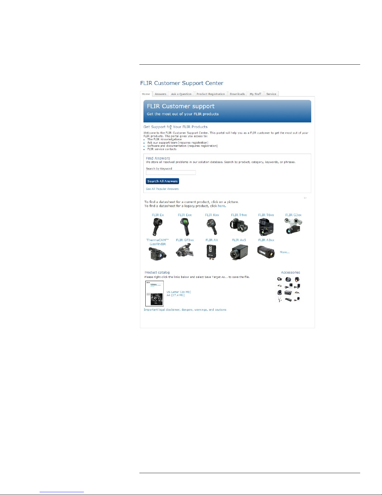
4.1 General
For customer help, visit:
http://support.flir.com
4.2 Submitting a question
To submit a question to the customer help team, you must be a registered user. It only
takes a few minutes to register online. If you only want to search the knowledgebase for
existing questions and answers, you do not need to be a registered user.
When you want to submit a question, make sure that you have the following information to
hand:
• The camera model
#T810170; r. AE/41948/41948; en-US
8
Page 17

4
Customer help
• The camera serial number
• The communication protocol, or method, between the camera and your device (for example, SD card reader, HDMI, Ethernet, USB, or FireWire)
• Device type (PC/Mac/iPhone/iPad/Android device, etc.)
• Version of any programs from FLIR Systems
• Full name, publication number, and revision number of the manual
4.3 Downloads
On the customer help site you can also download the following, when applicable for the
product:
• Firmware updates for your infrared camera.
• Program updates for your PC/Mac software.
• Freeware and evaluation versions of PC/Mac software.
• User documentation for current, obsolete, and historical products.
• Mechanical drawings (in *.dxf and *.pdf format).
• Cad data models (in *.stp format).
• Application stories.
• Technical datasheets.
• Product catalogs.
#T810170; r. AE/41948/41948; en-US
9
Page 18

5
Important information about FLIR
Kx3 series service
• Contact the service department before shipping the camera. Many problems can be resolved on the phone—if so, the camera does not need to be shipped.
• The camera must be thoroughly cleaned, decontaminated and disinfected before shipping to our service department. No hazardous residues are allowed on cameras. Such
residues include—but are not limited to—chemical fire-extinguishing compounds, radioactivity, biohazardous materials, and residues from chemical fires.
• FLIR Systems reserves the right to charge the full cost for the decontamination and disinfection of contaminated cameras that are shipped to our service department.
#T810170; r. AE/41948/41948; en-US
10
Page 19

6
Quick start guide
6.1 Quick start guide, FLIR K33
Follow this procedure:
1. Charge the battery for 4 hours before starting the camera for the first time, or until the
blue battery condition LED glows continuously.
2. Push the on/off button to turn on the camera.
3. Aim the camera toward the object of interest.
4. To freeze the image, pull and hold the trigger.
5. To return to the live image, release the trigger.
Note The function of the trigger is configured by a setting in FLIR Tools, see section
11.10.2 The User interface tab, page 27.
6.2 Quick start guide, FLIR K53
Follow this procedure:
1. Charge the battery for 4 hours before starting the camera for the first time, or until the
blue battery condition LED glows continuously.
2. Push the on/off button to turn on the camera.
3. Aim the camera toward the object of interest.
4. Pull the trigger to save an image.
5. Pull and hold the trigger to record a video clip.
6. Connect the camera to a computer, using the USB cable.
7. Do one of the following:
• Move the image to the computer using a drag-and-drop operation in Microsoft Windows Explorer.
Note Moving an image using a drag-and-drop operation does not delete the image in the camera.
• Move the image to the computer using FLIR Tools. In FLIR Tools you can analyze
the images and create PDF reports.
Note The function of the trigger is configured by a setting in FLIR Tools, see section
11.10.2 The User interface tab, page 27.
#T810170; r. AE/41948/41948; en-US
11
Page 20

7
List of accessories and services
Product name Part no.
Battery charger, incl. power supply with multi plugs
(Exx, Kxx)
Battery Li-ion 3.6 V, 4.4 Ah, 16 Wh
Carabiner strap T129915ACC
Cigarette lighter adapter kit, 12 VDC, 1.2 m/3.9 ft. T198509
In-truck charger
Lanyard strap T198416ACC
Li-Ion Battery pack 3.6 V 16 Wh T198310ACC
Neck strap
Retractable lanyard T127722ACC
Transport case Kxx
Tripod Adapter, Kxx T198457ACC
USB cable Std A <-> Mini-B
T198125
T199368ACC
T198322ACC
T127724ACC
T198441ACC
1910423
#T810170; r. AE/41948/41948; en-US
12
Page 21
8
System configuration overview
8.1 Figure
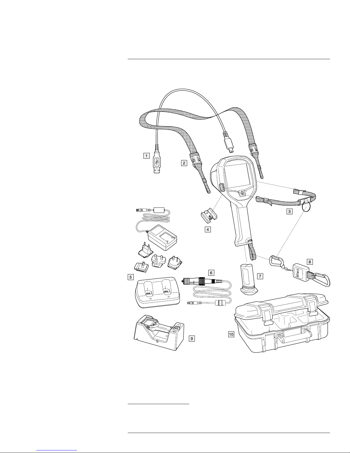
8.2 Explanation
1. FLIR P/N: 1910423, USB cable Std A <-> Mini-B
2. FLIR P/N: T127724ACC, Neck strap
1. The inclusion of this item is dependent on model.
#T810170; r. AE/41948/41948; en-US
1
13
Page 22

8
System configuration overview
3. FLIR P/N: T198416ACC, Strap lanyard
4. FLIR P/N: T198457ACC, Tripod Adapter, Kxx
2
2
5. FLIR P/N: T198125, Battery charger, incl. power supply with multi plugs
6. FLIR P/N: T198509, Cigarette lighter adapter kit, 12 VDC, 1.2 m/3.9 ft
7. FLIR P/N: T198310ACC, Li-Ion Battery pack 3.6 V 16 Wh
8. FLIR P/N: T127722ACC, Retractable lanyard
2
9. FLIR P/N: T198322ACC, In-truck charger
10. FLIR P/N: T198441ACC, Transport case Kxx
2. The inclusion of this item is dependent on model.
#T810170; r. AE/41948/41948; en-US
14
Page 23

9
System parts
9.1 Camera parts
9.1.1 Figure
9.1.2 Explanation
1. USB Mini-B connector: Connect to a computer to download images (FLIR K53 only)
and change settings using FLIR Tools.
2. Attachment point for the lanyard strap/neck strap (left and right sides).
3. Eccentric latch to secure the battery.
4. On/off button. This button has three functions:
• Push the on/off button to turn on the camera.
• Push and hold the on/off button for more than 3 seconds but less than 10 seconds
to put the camera into standby mode. The camera then automatically turns off after
6 hours.
• Push and hold the on/off button for more than 10 seconds to turn off the camera.
5. Pin hole for setting of the temperature unit (°C/°F).
6. Connectors for the in-truck charger.
7. Trigger.
8. Mount for the tripod adapter.
9. Attachment point for the retractable lanyard.
10. Battery.
#T810170; r. AE/41948/41948; en-US
15
Page 24

9
System parts
9.2 Lanyard strap and retractable lanyard
9.3 Handle strap and retractable lanyard
#T810170; r. AE/41948/41948; en-US
16
Page 25

9
System parts
9.4 Neck strap
#T810170; r. AE/41948/41948; en-US
17
Page 26

10
Screen elements
10.1 Figure
10.2 Explanation
1. Low-sensitivity mode indicator. The indicator is displayed when the camera identifies a
hot area and automatically switches to the low-sensitivity mode.
2. Overheating indicator. The indicator provides a visual warning to the user that the thermal imager is about to shut down due to internal overheating.
3. Reference bar.
4. Temperature bar.
5. Spotmeter temperature.
6. Battery condition indicator.
7. Spotmeter.
10.3 Battery condition indicator
Battery condition indicator Explanation
75% power.
50% power.
25% power.
Flashing indicator. At least 5 minutes of available
power remains.
#T810170; r. AE/41948/41948; en-US
18
Page 27

11
Operation
CAUTION
Do not use the FLIR K series camera without the correct training. If the persons that operate the camera
do not have the correct training, an incorrect analysis of the infrared images can occur. Thus, incorrect
decisions during the firefighting can be made.
The training must include:
• How a thermal camera operates and its limits
• How to interpret an image
• How to work safely with the camera.
11.1 Removing the battery
Follow this procedure:
1. Pull the eccentric latch.
2. Pull out the battery from the battery compartment.
11.1.1 Charging the battery
WARNING
Make sure that you install the socket-outlet near the equipment and that it is easy to get access to.
#T810170; r. AE/41948/41948; en-US
19
Page 28

11
Operation
11.1.1.1 General
Charge the battery for 4 hours before starting the camera for the first time, or until the blue
battery condition LED glows continuously.
11.1.1.2 Procedure
Follow this procedure:
1. Put the battery in the standalone battery charger.
2. Connect the power supply cable plug to the connector on the standalone battery
charger.
3. Connect the power supply mains-electricity plug to a mains socket.
4. Disconnect the power supply cable plug when the blue battery condition LED glows
continuously.
11.2 Turning on and turning off the camera
• Push the on/off button to turn on the camera.
• Push and hold the on/off button for more than 3 seconds but less than 10 seconds to
put the camera into standby mode. The camera then automatically turns off after 6
hours.
• Push and hold the on/off button for more than 10 seconds to turn off the camera.
11.3 Basic mode
The camera features one camera mode: Basic mode. This is a multipurpose mode for the
initial fire attack with life-saving operations and control of the fire. The camera automatically switches between the high-sensitivity range and the low-sensitivity range, to maintain
an optimal infrared image while at the same time maintaining a safe and consistent heat
colorization of the fire scene. This automatic switching of ranges occurs when objects with
a temperature above 150°C (302°F) enter the field of view of the camera.
• Automatic range.
• Colorization of heat: +150 to +650°C (+302 to +1202°F).
• High-sensitivity range: –20 to +150°C (–4 to +302°F).
• Low-sensitivity range: 0 to +650°C (+32 to +1202°F).
#T810170; r. AE/41948/41948; en-US
20
Page 29

11
Operation
11.3.1 Automatic temperature range selection
11.3.1.1 General
The automatic temperature range selection is based on a measured area defined by a rectangle covering (x1, y1) = (15% of the width, 15% of the height) to (x2, y2) = (85% of the
width, 85% of the height) of the LCD area. See the figure in section 11.3.1.2.
An automatic change from the high-sensitivity range to the low-sensitivity range occurs if
more than 2% of the pixels within the measured area constantly (for more than 1 second)
have a temperature above the maximum temperature of the high-sensitivity range.
An automatic change from low-sensitivity range to high-sensitivity range occurs if more
than 98% of the pixels within the measured area constantly have, for more than 1 second,
a temperature lower than 50°C (122°F) below the maximum temperature of the high-sensitivity range.
11.3.1.2 Figure
11.3.1.3 Explanation
1. LCD area.
2. Area activating the automatic range change.
11.4 Saving an image (FLIR K53)
11.4.1 General
You can save images to the camera’s archive.
Note The maximum number of images that can be saved in the archive is 200. When
the number of images exceeds 200, images are deleted on a first-in, first-out basis, i.e.,
the 201st image will delete the 1st image, the 202nd image will delete the 2nd image, and
so on.
#T810170; r. AE/41948/41948; en-US
21
Page 30

11
Operation
11.4.2 Figure
11.4.3 Procedure
Note The function of the trigger is configured by a setting in FLIR Tools, see section
11.10.2 The User interface tab, page 27.
Follow this procedure:
1. Aim the camera toward an object of interest.
2. To save an image, pull the trigger.
11.5 Recording a video clip (FLIR K53)
11.5.1 General
You can record video clips and save them to the camera’s archive.
11.5.2 Figure
11.5.3 Procedure
Note The function of the trigger is configured by a setting in FLIR Tools, see section
11.10.2 The User interface tab, page 27.
#T810170; r. AE/41948/41948; en-US
22
Page 31

11
Operation
Follow this procedure:
1. Aim the camera toward an object of interest.
2. Depending on the Trigger button setting in FLIR Tools, do one of the following to start
the recording:
• With the Rec. on/off setting, pull the trigger.
• With the Record video setting, pull and hold the trigger.
3. A blinking circle in the middle left part of the screen indicates that the camera is currently recording a video clip.
4. Depending on the Trigger button setting in FLIR Tools, do one of the following to stop
the recording:
• With the Rec. on/off setting, pull the trigger.
• With the Record video setting, release the trigger.
11.6 Continuous video recording (FLIR K53)
11.6.1 General
You can configure the camera to start a continuous video recording when you turn on the
camera. The recording cannot be stopped.
Note The continuous video recording functionality is configured by a setting in FLIR
Tools, see section 11.10.2 The User interface tab, page 27.
11.7 Freezing the image
11.7.1 General
You can freeze the image.
11.7.2 Figure
11.7.3 Procedure
Note The function of the trigger is configured by a setting in FLIR Tools, see section
11.10.2 The User interface tab, page 27.
#T810170; r. AE/41948/41948; en-US
23
Page 32

11
Operation
Follow this procedure:
1. Aim the camera toward an object of interest.
2. Do the following:
• To freeze the image, pull and hold the trigger.
• To return to the live image, release the trigger.
11.8 Changing the temperature unit
The camera displays temperatures in ℃ or ℉. You change the temperature unit by pushing a button behind the pin hole.
Note It is also possible to change the temperature unit using FLIR Tools. See section
11.10.2 The User interface tab, page 27.
Follow this procedure:
1. Turn on the camera.
2. Use a paper clip or a similar small item to push the button behind the pin hole.
11.9 Connecting the camera to a computer
11.9.1 General
You can connect the camera to a computer, using the USB cable.
Once connected, you can do the following:
• Change the camera settings using the FLIR Tools software. See section 11.10 Chang-
ing settings in FLIR Tools, page 26.
• Applicable to FLIR K53: Move the images and video clips from the camera’s archive to
the computer.
• Applicable to FLIR K53: Import the images into the FLIR Tools software.
#T810170; r. AE/41948/41948; en-US
24
Page 33

11
Operation
11.9.2 Procedure
Follow this procedure:
1. Fold up the rubber cover at the top of the camera.
2. Hold the metal ring firmly.
3. Rotate the ring about 90° counter-clockwise.
4. Pull out the plastic insert.
CAUTION
The plastic insert has an O-ring seal. Do not damage the O-ring seal.
5. Connect the USB cable to the USB Mini-B connector in the connector bay.
#T810170; r. AE/41948/41948; en-US
25
Page 34

11
Operation
6. Applicable to FLIR K53:
• Move the images to the computer using a drag-and-drop operation in Microsoft
Windows Explorer.
Note Moving an image using a drag-and-drop operation does not delete the image in the camera.
• Move the images to the computer using FLIR Tools.
11.10 Changing settings in FLIR Tools
11.10.1 The General settings tab
11.10.1.1 Figure
11.10.1.2 Explanation
Regional settings area: To synchronize the camera’s date and time settings with the computer, select the checkbox.
Firmware info area: To check whether a newer version of the camera firmware exists, click
Check for updates and follow the on-screen instructions.
Restore to factory default area: To restore all camera settings to the factory defaults, click
Restore.
#T810170; r. AE/41948/41948; en-US
26
Page 35

11
Operation
11.10.2 The User interface tab
11.10.2.1 Figure
11.10.2.2 Explanation
Camera mode area: The camera features one camera mode: Basic mode. For more information, see section 11.3 Basic mode, page 20.
Trigger button area: The camera has a trigger button. With the settings in the Trigger button area, you can select the function of the trigger button. You select what will happen
when you click (short press) the trigger button and what will happen when you hold (long
press) the trigger button.
• No action, No action: Select to disable any functionality of the trigger button. Nothing
will happen when you press the trigger.
• No action, Freeze image: Select to make the camera freeze the image when you press
and hold the trigger. The image will unfreeze when you release the trigger. Nothing will
happen when you press the trigger momentarily.
• No action, Record video (not applicable to the FLIR K33): Select to make the camera
start a recording when you press and hold the trigger. The recording will stop when you
release the trigger. Nothing will happen when you press the trigger momentarily.
• Save image, No action (not applicable to the FLIR K33): Select to make the camera
save an image when you press the trigger momentarily. Nothing will happen when you
press and hold the trigger.
• Save image, Freeze image (not applicable to the FLIR K33): Select to make the camera
save an image when you press the trigger momentarily and freeze the image when you
press and hold the trigger. The image will unfreeze when you release the trigger.
• Save image, Record video (not applicable to the FLIR K33): Select to make the camera
save an image when you press the trigger momentarily and start a recording when you
press and hold the trigger. The recording will stop when you release the trigger.
• Rec. on/off, No action (not applicable to the FLIR K33): Select to make the camera start
a recording when you press the trigger and stop the recording when you press the trigger again. Nothing will happen when you press and hold the trigger.
• Continuous rec. (trigger disabled) (not applicable to the FLIR K33): Select to make the
camera start a continuous video recording when you turn on the camera. The recording
cannot be stopped. Nothing will happen when you press the trigger.
#T810170; r. AE/41948/41948; en-US
27
Page 36

11
Operation
Gain mode area:
• Auto gain mode: Select to make the camera automatically switch between the high-
sensitivity range and the low-sensitivity range, depending on the scene temperature.
The temperature level at which the camera switches between the two modes is 150°C
(302°F).
• Low gain mode: Select to make the camera operate in the low-sensitivity range only.
This has the advantage that the camera does not perform a non-uniformity correction
(NUC) when an object with a temperature higher than 150°C (302°F) enters the scene.
However, the disadvantage is lower sensitivity and a higher level of signal noise.
Temperature unit area: To select a different temperature unit, click Celsius or Fahrenheit.
Thermal indication area:
• Digital readout only: Select to display the thermal information in the image as the tem-
perature of the spotmeter only. In modes with automatic heat colorization, the colorization of the image will remain but the static heat color reference icon will not be
displayed.
• Reference bar: In modes with automatic heat indication colorization, a vertical heat col-
or reference bar is displayed in the thermal indication area. This static icon shows how
heat colors are applied to the range of the camera mode. The colors yellow, orange,
and red correspond to a temperature-dependent change in hue as the temperature
increases.
• Temp bar: Select to display the thermal information in the image as a temperature bar,
similar to a thermometer. This displays a dynamic vertical temperature bar on the righthand side of the image. The top of the dynamic bar represents the temperature of the
measured spot. In modes with automatic heat colorization, the colorization of the image
will remain, with a static heat color reference bar displayed next to the temperature bar.
Add custom boot image area: To select an image of your choice to appear during start-up,
click Browse, and navigate to the image file. This is useful for, for example, identifying your
fire department’s cameras. By incorporating your fire department’s logo, and a unique
identity number in the image, you can keep track of your cameras. This image can also be
accessed from the camera menu.
#T810170; r. AE/41948/41948; en-US
28
Page 37

12
In-truck charger (optional
accessory)
12.1 Introduction
Thank you for choosing the FLIR Kx3 series in-truck charger from FLIR Systems.
The in-truck charger is intended to be mounted on a flat surface in the cab, in one of the
equipment lockers, or in another suitable compartment on the fire engine. The in-truck
charger has five ports for cable routing—one through the rear of the metal bracket and
one port on each side of the in-truck charger.
The in-truck charger can also be powered using a standard FLIR Systems power supply,
and has a battery charger located at the lower front of the unit.
#T810170; r. AE/41948/41948; en-US
29
Page 38

12
In-truck charger (optional accessory)
12.2 Parts and functions
1. Top cover.
2. LED indicator for the camera charger.
3. Hole for attaching the charger housing to the metal bracket.
4. Connectors in the cradle.
5. Connector to power the charger using a standard FLIR Systems power supply.
6. Hole for attaching the charger housing to the metal bracket.
7. LED indicator for the battery charger.
8. Battery slot.
9. Eccentric latch to secure the battery during charging.
10. Cable port (1 of 4).
Note There is also one port through the rear of the metal bracket.
11. Routing support.
12. 12–24 VDC cable plinth.
13. Recess for the cable.
14. Routing support.
12.3 Choosing a suitable position
Before mounting the in-truck charger, take a few minutes to think about a suitable position.
The mounting position should be protected from rain and road splash, and it should be
reasonably easy to install a permanent cable running from the fire engine’s 12–24 VDC
system to the in-truck charger.
Additional considerations may be important, e.g., getting access to panels and equipment
behind the in-truck charger.
#T810170; r. AE/41948/41948; en-US
30
Page 39

12
In-truck charger (optional accessory)
12.4 Recommended cable area and fuse
Cable area 1.5 mm2(No. 15 AWG)
Fuse 5 A
12.5 Mounting instructions
Follow this procedure:
1. Permanently install a cable running from the fire engine’s 12–24 VDC system to the selected mounting position of the in-truck charger. Do not connect this cable to the 12–
24 VDC system at this time. The routing must include a fuse installed close to the battery. See above for the fuse recommendation.
2. Remove the two screws that hold the metal bracket.
3. Remove the metal bracket.
4. Use the metal bracket as a template to mark where the mounting holes should be
drilled.
5. Drill the holes.
6. Mount the metal bracket using the rivets and/or screws that come with the in-truck
charger.
7. Connect the cable to the cable plinth on the rear of the in-truck charger.
Note Take note of the polarity when you connect the cable to the cable plinth.
8. Route the cable so that it exits through the cable port of your choice.
9. Mount the in-truck charger to the metal bracket using the two screws that you removed
in Step 2 above.
10. Permanently connect the cable to the fire engine’s 12–24 VDC system.
12.6 Charging the camera
Follow this procedure:
1. Pull up the top cover of the in-truck charger.
2. Push the camera into position.
3. Push down the top cover.
The charging of the camera has now started, and is finished when the blue light glows
continuously. Charging a fully depleted camera takes approximately 4 hours.
12.7 Charging a battery separately
FLIR Kx3 series batteries can be charged separately using the battery charger at the lower
front of the unit.
Follow this procedure:
1. Pull the eccentric latch on the bottom of the camera.
2. Pull out the battery from the camera.
3. Push the battery into the slot at the lower front of the charger.
4. Secure the battery using the eccentric latch on the charger.
The charging of the battery has now started, and is finished when the blue light glows
continuously. Charging a fully depleted battery takes approximately 4 hours.
#T810170; r. AE/41948/41948; en-US
31
Page 40

12
In-truck charger (optional accessory)
12.8 Cleaning
CAUTION
Disconnect the in-truck charger from the fire engine’s 12–24 VDC system before cleaning.
The in-truck charger can be cleaned using warm water or a weak detergent solution. Do
not use solvents or similar liquids.
12.9 Customer support
Should you experience any problems, do not hesitate to contact our Customer Support at
http://support.flir.com.
#T810170; r. AE/41948/41948; en-US
32
Page 41

13
Technical data
Table of contents
13.1 Online field-of-view calculator....................................................... ...... 33
13.2 Note about technical data ................................................................... 33
13.3 Note about authoritative versions.............................................. .......... 33
13.4 FLIR K33 .. ....... ....... ....... ................... ....... ....... ....... ................... ....... . 34
13.5 FLIR K53 .. ....... ....... ....... ................... ....... ....... ....... ................... ....... . 38
13.6 In-truck charger ................................................................................ 42
13.1 Online field-of-view calculator
Please visit http://support.flir.com and click the photo of the camera series for field-of-view
tables for all lens–camera combinations.
13.2 Note about technical data
FLIR Systems reserves the right to change specifications at any time without prior notice.
Please check http://support.flir.com for latest changes.
13.3 Note about authoritative versions
The authoritative version of this publication is English. In the event of divergences due to
translation errors, the English text has precedence.
Any late changes are first implemented in English.
#T810170; r. AE/41948/41948; en-US
33
Page 42

Technical data13
13.4 FLIR K33
P/N: 72203-0411
Rev.: 41168
General description
The FLIR K33 is a robust and reliable infrared camera designed to perform under extremely severe conditions. The FLIR K33 has an intuitive interface with a design that makes it easy to control even with a
gloved hand. The crisp and clear image helps you to navigate through smoke and to make quick and accurate decisions.
Benefits:
• Robust and reliable: The FLIR K33 is designed to meet tough operating conditions. It can withstand a
drop from 2 m (6.5 ft.) onto a concrete floor, is water resistant to IP67, and is fully operational up to
+85°C (+185°F), or +260°C (+500°F) for 5 min.
• Clear and crisp thermal images: The maintenance-free uncooled microbolometer sensor produces
clear and detail-rich images of 240 × 180 pixels which have been further improved with FSX, a digital
image processing enhancement technique. Thermal images are presented on a large, bright 4″ display, helping you to navigate and to make quick and accurate decisions.
• Easy-to-use—also in a gloved firefighter’s hand: An intuitive and simple user interface allows you to focus on the job. The FLIR K33 can be controlled by just one large button on top of the unit. Ideal for a
gloved firefighter’s hand.
Imaging and optical data
IR resolution 240 × 180 pixels
Thermal sensitivity/NETD < 40 mK @ +30°C (+86°F)
Field of view (FOV)
Depth of field 0.84 m to infinity (33 in. to infinity)
Focal length 9 mm (0.35 in.)
Spatial resolution (IFOV)
F-number 1.25
Image frequency 60 Hz
Focus Fixed
Detector data
Detector type Focal plane array (FPA), uncooled microbolometer
Spectral range
Pitch 25 µm
Image presentation
Display 4 in. LCD, 320 × 240 pixels, backlit
Auto range Yes, selectable on/off using FLIR Tools
Contrast optimization Digital image enhancement using FSX
Image presentation modes
Image modes TI Basic fire-fighting mode
51° × 38°
3.6 mrad
7.5–13 µm
#T810170; r. AE/41948/41948; en-US
34
Page 43

Technical data13
Measurement
Object temperature range
Accuracy ±4°C (±7.2°F) or ±4% of reading, for ambient tem-
Measurement analysis
Spotmeter
Isotherm Yes
Set-up
Set-up commands Local adaptation of units, date and time formats
Languages English
Video streaming
Non-radiometric IR video streaming Uncompressed colorized video using USB
• –20°C to +150°C (–4°F to +302°F)
• 0°C to +650°C (+32°F to +1202°F)
perature 10°C to 35°C (+50°F to 95°F)
1
USB
USB USB Mini-B
Compatibility
Compatible with FLIR software FLIR Tools
Data communication interfaces
Interfaces
Power system
Battery type Li Ion
Battery voltage 3.6 V
Battery capacity
Battery operating time
Charging system
Charging time 2 h to 85% capacity, charging status indicated by
Charging temperature 0°C to +45°C (+32°F to +113°F)
Power management Automatic shutdown and sleep mode
Start-up time from sleep mode
Start-up time < 17 s. (IR image, no GUI)
• Update from PC devices
• Data transfer to and from PC
4.4 Ah, at +20°C to +25°C (+68°F to +77°F)
Approx. 4 hours at +25°C (+77°F) ambient temperature and typical use
• Battery is charged inside the camera
• 2-bay charger
• Optional In-truck charger
LEDs
< 4 s.
Environmental data
Operating temperature range
Storage temperature range –40°C to +85°C (–40°F to +185°F)
#T810170; r. AE/41948/41948; en-US
• –20°C to +85°C (–4°F to +185°F)
• +150°C (+302°F): 15 min.
• +260°C (+500°F): 5 min.
35
Page 44

Technical data13
Environmental data
Humidity (operating and storage) IEC 60068-2-30/24 h 95% relative humidity +25°C
Relative humidity 95% relative humidity +25°C to +40°C (+77°F to
Directives Designed to meet NFPA 1801:2013 specification:
EMC
Magnetic fields EN 61 000-4-8, Test level 5 for continuous field (se-
Encapsulation
Shock 25 g (IEC 60068-2-27)
Vibration 2 g (IEC 60068-2-6)
Drop 2 m (6.6 ft.) on concrete floor (IEC 60068-2-31)
Safety (power supply) CE/EN/UL/CSA/PSE 60950-1
to +40°C (+77°F to +104°F) / 2 cycles
+104°F) non-condensing
• Vibration
• Impact acceleration resistance
• Corrosion
• Viewing surface abrasion
• Heat resistance
• Heat and flame
• Product label durability
• EN 61000-6-2:2005 (Immunity)
• EN 61000-6-3: 2011 (Emission)
• FCC 47 CFR Part 15 B (Emission)
vere industrial environment)
IP 67 (IEC 60529)
Physical data
Camera weight, incl. battery 1.1 ±0.05 kg (2.4 ±0.1 lb.)
Battery weight 0.152 kg (0.3 lb.)
Camera size (L × W × H) 120 × 125 × 280 mm (4.7 × 4.9 × 11 in.)
Tripod mounting UNC ¼"-20 (adapter needed)
Material
Shipping information
List of contents
Packaging, weight 5.7 kg (12.6 lb.)
Packaging, size 500 × 190 × 370 mm (19.7 × 7.5 × 14.6 in.)
EAN-13 7332558011515
UPC-12
Country of origin
• PPSU
• Silicon rubber
• Aluminium, cast
• Flame-resistant magnesium alloy
• Infrared camera
• Battery (2 ea.)
• Battery charger
• Hard transport case
• Lanyard strap
• Neck strap
• Power supply
• Printed documentation
• Retractable lanyard
• USB cable
845188012465
Estonia
#T810170; r. AE/41948/41948; en-US
36
Page 45

Technical data13
Supplies & accessories:
• 1910423; USB cable Std A <-> Mini-B
• T198509; Cigarette lighter adapter kit, 12 VDC, 1.2 m/3.9 ft.
• T198125; Battery charger, incl. power supply with multi plugs (Exx, Kxx)
• T198310ACC; Li-Ion Battery pack 3.6 V 16 Wh
• T127724ACC; Neck strap
• T127722ACC; Retractable lanyard
• T198416ACC; Lanyard strap
• T198457ACC; Tripod Adapter, Kxx
• T198441ACC; Transport case Kxx
• T198322ACC; In-truck charger
• T199368ACC; Battery Li-ion 3.6 V, 4.4 Ah, 16 Wh
• T129915ACC; Carabiner strap
#T810170; r. AE/41948/41948; en-US
37
Page 46

Technical data13
13.5 FLIR K53
P/N: 72203-0511
Rev.: 41168
General description
The FLIR K53 is a robust and reliable infrared camera designed to perform under extremely severe conditions. The FLIR K53 has an intuitive interface with a design that makes it easy to control even with a
gloved hand. The crisp and clear image helps you to navigate through smoke and to make quick and accurate decisions.
Benefits:
• Robust and reliable: The FLIR K53 is designed to meet tough operating conditions. It can withstand a
drop from 2 m (6.5 ft.) onto a concrete floor, is water resistant to IP67, and is fully operational up to
+85°C (+185°F), or +260°C (+500°F) for 5 min.
• Clear and crisp thermal images: The maintenance-free uncooled microbolometer sensor produces
clear and detail-rich images of 320 × 240 pixels which have been further improved with FSX, a digital
image processing enhancement technique. Thermal images are presented on a large, bright 4″ display, helping you to navigate and to make quick and accurate decisions.
• Easy-to-use—also in a gloved firefighter’s hand: An intuitive and simple user interface allows you to focus on the job. The FLIR K53 can be controlled by just one large button on top of the unit. Ideal for a
gloved firefighter’s hand.
• Recording
Imaging and optical data
IR resolution 320 × 240 pixels
Thermal sensitivity/NETD < 30 mK @ +30°C (+86°F)
Field of view (FOV)
Depth of field 0.84 m to infinity (33 in. to infinity)
Focal length 9 mm (0.35 in.)
Spatial resolution (IFOV)
F-number 1.25
Image frequency 60 Hz
Focus Fixed
Detector data
Detector type Focal plane array (FPA), uncooled microbolometer
Spectral range
Pitch 25 µm
Image presentation
Display 4 in. LCD, 320 × 240 pixels, backlit
Auto range Yes, selectable on/off using FLIR Tools
Contrast optimization Digital image enhancement using FSX
Image presentation modes
Image modes TI Basic fire-fighting mode
51° × 38°
2.8 mrad
7.5–13 µm
#T810170; r. AE/41948/41948; en-US
38
Page 47

Technical data13
Measurement
Object temperature range
Accuracy ±4°C (±7.2°F) or ±4% of reading, for ambient tem-
Measurement analysis
Spotmeter
Isotherm Yes
Set-up
Set-up commands Local adaptation of units, date and time formats
Languages English
Storage of images
Image storage
Storage media Internal flash memory
Image storage capacity 200 files in total
• –20°C to +150°C (–4°F to +302°F)
• 0°C to +650°C (+32°F to +1202°F)
perature 10°C to 35°C (+50°F to 95°F)
1
Standard JPEG
NOTE
The total number of files is co-dependent on the
number of saved video clips.
Image storage mode IR only
File formats Standard JPEG
Image annotations
Report generation Separate software (FLIR Tools)
Video recording in camera
Non-radiometric IR video recording MPEG-4 to internal flash memory
Storage capacity 200 files in total, with a maximum duration of 5 mi-
Video streaming
Non-radiometric IR video streaming
USB
USB USB Mini-B
Compatibility
Compatible with FLIR software FLIR Tools
nutes each.
NOTE
The total number of files is co-dependent on the
number of saved images.
Uncompressed colorized video using USB
Data communication interfaces
Interfaces
#T810170; r. AE/41948/41948; en-US
• Update from PC devices
• Data transfer to and from PC
39
Page 48

Technical data13
Power system
Battery type Li Ion
Battery voltage 3.6 V
Battery capacity 4.4 Ah, at +20°C to +25°C (+68°F to +77°F)
Battery operating time Approx. 4 hours at +25°C (+77°F) ambient temper-
Charging system
Charging time
Charging temperature 0°C to +45°C (+32°F to +113°F)
Power management Automatic shutdown and sleep mode
Start-up time from sleep mode
Start-up time < 17 s. (IR image, no GUI)
ature and typical use
• Battery is charged inside the camera
• 2-bay charger
• Optional In-truck charger
2 h to 85% capacity, charging status indicated by
LEDs
< 4 s.
Environmental data
Operating temperature range
Storage temperature range –40°C to +85°C (–40°F to +185°F)
Humidity (operating and storage) IEC 60068-2-30/24 h 95% relative humidity +25°C
Relative humidity 95% relative humidity +25°C to +40°C (+77°F to
Directives Designed to meet NFPA 1801:2013 specification:
EMC
Magnetic fields EN 61 000-4-8, Test level 5 for continuous field (se-
Encapsulation IP 67 (IEC 60529)
Shock 25 g (IEC 60068-2-27)
Vibration
Drop
Safety (power supply) CE/EN/UL/CSA/PSE 60950-1
• –20°C to +85°C (–4°F to +185°F)
• +150°C (+302°F): 15 min.
• +260°C (+500°F): 5 min.
to +40°C (+77°F to +104°F) / 2 cycles
+104°F) non-condensing
• Vibration
• Impact acceleration resistance
• Corrosion
• Viewing surface abrasion
• Heat resistance
• Heat and flame
• Product label durability
• EN 61000-6-2:2005 (Immunity)
• EN 61000-6-3: 2011 (Emission)
• FCC 47 CFR Part 15 B (Emission)
vere industrial environment)
2 g (IEC 60068-2-6)
2 m (6.6 ft.) on concrete floor (IEC 60068-2-31)
Physical data
Camera weight, incl. battery 1.1 ±0.05 kg (2.4 ±0.1 lb.)
Battery weight 0.152 kg (0.3 lb.)
Camera size (L × W × H) 120 × 125 × 280 mm (4.7 × 4.9 × 11 in.)
#T810170; r. AE/41948/41948; en-US
40
Page 49

Technical data13
Physical data
Tripod mounting
Material
Shipping information
List of contents
Packaging, weight 5.7 kg (12.6 lb.)
Packaging, size 500 × 190 × 370 mm (19.7 × 7.5 × 14.6 in.)
EAN-13 7332558011522
UPC-12
Country of origin Estonia
UNC ¼"-20 (adapter needed)
• PPSU
• Silicon rubber
• Aluminium, cast
• Flame-resistant magnesium alloy
• Infrared camera
• Battery (2 ea.)
• Battery charger
• Hard transport case
• Lanyard strap
• Neck strap
• Power supply
• Printed documentation
• Retractable lanyard
• USB cable
845188012472
Supplies & accessories:
• 1910423; USB cable Std A <-> Mini-B
• T198509; Cigarette lighter adapter kit, 12 VDC, 1.2 m/3.9 ft.
• T198125; Battery charger, incl. power supply with multi plugs (Exx, Kxx)
• T198310ACC; Li-Ion Battery pack 3.6 V 16 Wh
• T127724ACC; Neck strap
• T127722ACC; Retractable lanyard
• T198416ACC; Lanyard strap
• T198457ACC; Tripod Adapter, Kxx
• T198441ACC; Transport case Kxx
• T198322ACC; In-truck charger
• T199368ACC; Battery Li-ion 3.6 V, 4.4 Ah, 16 Wh
• T129915ACC; Carabiner strap
#T810170; r. AE/41948/41948; en-US
41
Page 50

Technical data13
13.6 In-truck charger
P/N: T198322
Rev.: 28825
Power system
Charging time
Charging temperature 0°C to +45°C (+32°F to +113°F)
External power, connector type Screw terminal or HRS_UK60-3PT
DC operation 12/ 24 V DCnominal (11.1 - 28.0 V DC)
Power
Environmental data
Operating temperature range –40°C to +85°C (–40°F to +185°F)
Storage temperature range –40°C to +85°C (–40°F to +185°F)
Relative humidity Operational for non-condensing humidity between
EMC
Encapsulation IP 20
Bump
Vibration
< 4 hours
Max 36 Watts or 3000 mA at 12 VDC (5 amps
fuse)
5% and 95%.
• EN61000-6-3 Emission
• EN61000-6-2 Immunity
• FCC47CFR part 15 class B
• NFPA requirements
• ISO 7637-2 Road vehicles - Electrical disturbances from conduction and coupling Part 2:
Electrical transient conduction along supply
lines only
Operational after exposed to: 5 pulses/ in each axis/ direction (30 total) of 30g 11ms half sine profile
Operational after exposed to: 4, 3g rms random
profile. 8 hours in each axis.
Physical data
Weight 1.050 kg
Size (L × W × H) 380 mm × 180 mm × 153 mm (15 in. × 7.1 in. × 6
Material PC / ABS
Color Grey / black
Shipping information
List of contents
Packaging, weight 3.2 kg (7.0 lb.)
Packaging, size 435 × 245 × 167 mm (17.1 × 9.6 × 6.6 in.)
EAN-13 7332558005446
#T810170; r. AE/41948/41948; en-US
in.)
• Charger
• Documentation
• Card board box
4743254001282 (Estonia plant)
42
Page 51

Technical data13
Shipping information
UPC-12
Country of origin
Compatible with the following products
• 72201-0106; FLIR K45
• 72201-0206; FLIR K55
• 72202-0303; FLIR K65
845188005368
Estonia
#T810170; r. AE/41948/41948; en-US
43
Page 52

14
Mechanical drawings
[See next page]
#T810170; r. AE/41948/41948; en-US
44
Page 53

[6.36]
161,50
[4.46]
113
[8.04]
204
[11.08]
281,50
[3.29]
83,5
[2.5]
63,5
[4.87]
123,7
Basic dimension drawing
Kx3
Där ej annat anges/Unless otherwise stated
Kanter brutna
Edges broken
Hålkälsradier
Ra µm
Fillet radii
Ytjämnhet/Roughness
Blad/Sheet
Rev
Ritn nr/Drawing No
ArtNo.
Skala/Scale
Size
Datum/Date
Kontr/Check
Konstr/Drawn
Material
Ytbehandling/Surface treatment
Gen tol
Benämning/Denomination
Denna handling får ej delges annan, kopieras i
sin helhet eller delar utan vårt medgivande .
Överträdelse härav beivras med stöd av gällande lag.
FLIR SYSTEMS AB
This document must not be communicated or
copied completely or in part, without our permission.
Any infringement will lead to legal proceedings.
FLIR SYSTEMS AB
A3
Utdrag ur/Excerpt from ISO 2768-m
±0,1
±0,2
±0,3
±0,5
±0,8
(400)-1000
(120)-400
(30)-120
(6)-30
0,5-6
ISO 2768-mK
1(2)
1:2
A. LUND
2016-03-23
2016-03-29
A. LUND
Ändrad av/Modified by
Ändrad/Modified
1 2 3 4 5 6 7 8 9 10
A
B
C
D
E
F
G
H
1 32 54
C
F
B
D
G
E
A
Page 54

1/4"-20
Tripod adapter
13,5°
[0.55]
14
[0.98]
25
Kx3
Basic dimension drawing
Där ej annat anges/Unless otherwise stated
Kanter brutna
Edges broken
Hålkälsradier
Ra µm
Fillet radii
Ytjämnhet/Roughness
Blad/Sheet
Rev
Ritn nr/Drawing No
ArtNo.
Skala/Scale
Size
Datum/Date
Kontr/Check
Konstr/Drawn
Material
Ytbehandling/Surface treatment
Gen tol
Benämning/Denomination
Denna handling får ej delges annan, kopieras i
sin helhet eller delar utan vårt medgivande .
Överträdelse härav beivras med stöd av gällande lag.
FLIR SYSTEMS AB
This document must not be communicated or
copied completely or in part, without our permission.
Any infringement will lead to legal proceedings.
FLIR SYSTEMS AB
A3
Utdrag ur/Excerpt from ISO 2768-m
±0,1
±0,2
±0,3
±0,5
±0,8
(400)-1000
(120)-400
(30)-120
(6)-30
0,5-6
ISO 2768-mK
2(2)
1:2
-
A. LUND
2016-03-23
2016-03-29
A. LUND
Ändrad av/Modified by
Ändrad/Modified
1 2 3 4 5 6 7 8 9 10
A
B
C
D
E
F
G
H
1 32 54
C
F
B
D
G
E
A
Page 55

14,96
±0,04
380
±1
7,08
±0,04
180
±1
6,02
±0,04
153
±1
Mounting hole
6x ø6,3
Mounting hole
10x ø5,0
A
Basic dimensions
1(1)
T127865
ISO 2768-mK
0,5-6
(6)-30
(30)-120
(120)-400
±0,5
±0,3
±0,2
±0,1
Utdrag ur/Excerpt from ISO 2768-m
Där ej annat anges/Unless otherwise stated
Kanter brutna
Edges broken
Hålkälsradier
Ra µm
Fillet radii
Ytjämnhet/Roughness
Blad/Sheet
Rev
Ritn nr/Drawing No
Art.No.
Size
Kontr/Check
Konstr/Drawn
Material
A4
Ytbehandling/Surface treatment
Gen tol
Benämning/Denomination
Denna handling får ej delges annan, kopieras i
sin helhet eller delar utan vårt medgivande .
Överträdelse härav beivras med stöd av gällande lag.
FLIR SYSTEMS AB
This document must not be communicated or
copied completely or in part, without our permission.
Any infringement will lead to legal proceedings.
FLIR SYSTEMS AB
In-truck charger
P. MARCUS
P. MARCUS
2013-04-08
MABR
Datum/Date
Ändrad av/Modified by
1:5
Ändrad/Modified
Skala/Scale
2013-04-08
±0,8
(400)-1000
-
Page 56

15
CE Declaration of conformity
[See next page]
#T810170; r. AE/41948/41948; en-US
48
Page 57

Page 58

16
Cleaning, decontamination and
disinfection
16.1 Cleaning
16.1.1 Camera housing, cables, and other items
16.1.1.1 Liquids
Use one of these liquids:
• Warm water
• A weak detergent solution
16.1.1.2 Equipment
A soft cloth
16.1.1.3 Procedure
Follow this procedure:
1. Soak the cloth in the liquid.
2. Twist the cloth to remove excess liquid.
3. Clean the part with the cloth.
CAUTION
Do not apply solvents or similar liquids to the camera, the cables, or other items. This can cause damage.
16.1.2 Infrared lens
16.1.2.1 Liquids
Use one of these liquids:
• A commercial lens cleaning liquid with more than 30% isopropyl alcohol.
• 96% ethyl alcohol (C
16.1.2.2 Equipment
Cotton wool
CAUTION
If you use a lens cleaning cloth it must be dry. Do not use a lens cleaning cloth with the liquids that are given in section 16.1.2.1 above. These liquids can cause material on the lens cleaning cloth to become
loose. This material can have an unwanted effect on the surface of the lens.
16.1.2.3 Procedure
Follow this procedure:
1. Soak the cotton wool in the liquid.
2. Twist the cotton wool to remove excess liquid.
3. Clean the lens one time only and discard the cotton wool.
2H5
OH).
WARNING
Make sure that you read all applicable MSDS (Material Safety Data Sheets) and warning labels on containers before you use a liquid: the liquids can be dangerous.
#T810170; r. AE/41948/41948; en-US
50
Page 59

16
Cleaning, decontamination and disinfection
CAUTION
• Be careful when you clean the infrared lens. The lens has a delicate anti-reflective coating.
• Do not clean the infrared lens too vigorously. This can damage the anti-reflective coating.
16.2 Decontamination and disinfection
• The camera must be thoroughly cleaned, decontaminated and disinfected before shipping to our service department. No hazardous residues are allowed on cameras. Such
residues include—but are not limited to—chemical fire-extinguishing compounds, radioactivity, biohazardous materials, and residues from chemical fires.
• FLIR Systems reserves the right to charge the full cost for the decontamination and disinfection of contaminated cameras that are shipped to our service department.
#T810170; r. AE/41948/41948; en-US
51
Page 60

17
Maintenance, inspection, and
service
The following maintenance and inspection procedures apply.
17.1 Maintenance
After each use:
1. Clean the camera according to section 16.1 Cleaning, page 50.
2. Charge the battery according to section 11.1.1 Charging the battery, page 19.
17.2 Inspection
After each use:
1. Verify the function and integrity of the latch that secures the battery.
CAUTION
Make sure that you do not use a torque value that is more than 80 Ncm on the Torx T20 screw. Damage to the camera can occur if you do not obey this.
2. Inspect the lens for scratches.
3. Inspect the screen for scratches.
4. Inspect the camera body for damage.
5. Verify the function of all buttons and triggers.
6. Inspect the attachment point for the lanyard strap/neck strap, and the attachment point
for the retractable lanyard.
17.3 Service
For contact details to our service departments, use the following link:
http://support.flir.com/service
#T810170; r. AE/41948/41948; en-US
52
Page 61

18
Storage conditions
The following storage conditions apply.
Storage temperature range –40°C to +85°C (–40°F to +185°F)
Storage humidity IEC 60068-2-30/24 h 95% relative humidity +25°C
to +40°C (+77°F to +104°F) / 2 cycles
#T810170; r. AE/41948/41948; en-US
53
Page 62

19
About FLIR Systems
FLIR Systems was established in 1978 to pioneer the development of high-performance
infrared imaging systems, and is the world leader in the design, manufacture, and marketing of thermal imaging systems for a wide variety of commercial, industrial, and government applications. Today, FLIR Systems embraces five major companies with outstanding
achievements in infrared technology since 1958—the Swedish AGEMA Infrared Systems
(formerly AGA Infrared Systems), the three United States companies Indigo Systems, FSI,
and Inframetrics, and the French company Cedip.
Since 2007, FLIR Systems has acquired several companies with world-leading expertise
in sensor technologies:
• Extech Instruments (2007)
• Ifara Tecnologías (2008)
• Salvador Imaging (2009)
• OmniTech Partners (2009)
• Directed Perception (2009)
• Raymarine (2010)
• ICx Technologies (2010)
• TackTick Marine Digital Instruments (2011)
• Aerius Photonics (2011)
• Lorex Technology (2012)
• Traficon (2012)
• MARSS (2013)
• DigitalOptics micro-optics business (2013)
• DVTEL (2015)
• Point Grey Research (2016)
• Prox Dynamics (2016)
Figure 19.1 Patent documents from the early 1960s
FLIR Systems has three manufacturing plants in the United States (Portland, OR, Boston,
MA, Santa Barbara, CA) and one in Sweden (Stockholm). Since 2007 there is also a
#T810170; r. AE/41948/41948; en-US
54
Page 63

19
About FLIR Systems
manufacturing plant in Tallinn, Estonia. Direct sales offices in Belgium, Brazil, China,
France, Germany, Great Britain, Hong Kong, Italy, Japan, Korea, Sweden, and the USA—
together with a worldwide network of agents and distributors—support our international
customer base.
FLIR Systems is at the forefront of innovation in the infrared camera industry. We anticipate market demand by constantly improving our existing cameras and developing new
ones. The company has set milestones in product design and development such as the introduction of the first battery-operated portable camera for industrial inspections, and the
first uncooled infrared camera, to mention just two innovations.
Figure 19.2 1969: Thermovision Model 661. The
camera weighed approximately 25 kg (55 lb.), the
oscilloscope 20 kg (44 lb.), and the tripod 15 kg
(33 lb.). The operator also needed a 220 VAC generator set, and a 10 L (2.6 US gallon) jar with liquid
nitrogen. To the left of the oscilloscope the Polaroid
attachment (6 kg/13 lb.) can be seen.
Figure 19.3 2015: FLIR One, an accessory to
iPhone and Android mobile phones. Weight: 90 g
(3.2 oz.).
FLIR Systems manufactures all vital mechanical and electronic components of the camera
systems itself. From detector design and manufacturing, to lenses and system electronics,
to final testing and calibration, all production steps are carried out and supervised by our
own engineers. The in-depth expertise of these infrared specialists ensures the accuracy
and reliability of all vital components that are assembled into your infrared camera.
19.1 More than just an infrared camera
At FLIR Systems we recognize that our job is to go beyond just producing the best infrared
camera systems. We are committed to enabling all users of our infrared camera systems
to work more productively by providing them with the most powerful camera–software
combination. Especially tailored software for predictive maintenance, R & D, and process
monitoring is developed in-house. Most software is available in a wide variety of
languages.
We support all our infrared cameras with a wide variety of accessories to adapt your equipment to the most demanding infrared applications.
#T810170; r. AE/41948/41948; en-US
55
Page 64

19
About FLIR Systems
19.2 Sharing our knowledge
Although our cameras are designed to be very user-friendly, there is a lot more to thermography than just knowing how to handle a camera. Therefore, FLIR Systems has founded
the Infrared Training Center (ITC), a separate business unit, that provides certified training
courses. Attending one of the ITC courses will give you a truly hands-on learning
experience.
The staff of the ITC are also there to provide you with any application support you may
need in putting infrared theory into practice.
19.3 Supporting our customers
FLIR Systems operates a worldwide service network to keep your camera running at all
times. If you discover a problem with your camera, local service centers have all the equipment and expertise to solve it within the shortest possible time. Therefore, there is no need
to send your camera to the other side of the world or to talk to someone who does not
speak your language.
#T810170; r. AE/41948/41948; en-US
56
Page 65

20
History of infrared technology
Before the year 1800, the existence of the infrared portion of the electromagnetic spectrum
wasn't even suspected. The original significance of the infrared spectrum, or simply ‘the infrared’ as it is often called, as a form of heat radiation is perhaps less obvious today than it
was at the time of its discovery by Herschel in 1800.
Figure 20.1 Sir William Herschel (1738–1822)
The discovery was made accidentally during the search for a new optical material. Sir William Herschel – Royal Astronomer to King George III of England, and already famous for
his discovery of the planet Uranus – was searching for an optical filter material to reduce
the brightness of the sun’s image in telescopes during solar observations. While testing
different samples of colored glass which gave similar reductions in brightness he was intrigued to find that some of the samples passed very little of the sun’s heat, while others
passed so much heat that he risked eye damage after only a few seconds’ observation.
Herschel was soon convinced of the necessity of setting up a systematic experiment, with
the objective of finding a single material that would give the desired reduction in brightness
as well as the maximum reduction in heat. He began the experiment by actually repeating
Newton’s prism experiment, but looking for the heating effect rather than the visual distribution of intensity in the spectrum. He first blackened the bulb of a sensitive mercury-inglass thermometer with ink, and with this as his radiation detector he proceeded to test
the heating effect of the various colors of the spectrum formed on the top of a table by
passing sunlight through a glass prism. Other thermometers, placed outside the sun’s
rays, served as controls.
As the blackened thermometer was moved slowly along the colors of the spectrum, the
temperature readings showed a steady increase from the violet end to the red end. This
was not entirely unexpected, since the Italian researcher, Landriani, in a similar experiment
in 1777 had observed much the same effect. It was Herschel, however, who was the first
to recognize that there must be a point where the heating effect reaches a maximum, and
that measurements confined to the visible portion of the spectrum failed to locate this
point.
Figure 20.2 Marsilio Landriani (1746–1815)
#T810170; r. AE/41948/41948; en-US
57
Page 66

20
History of infrared technology
Moving the thermometer into the dark region beyond the red end of the spectrum, Herschel confirmed that the heating continued to increase. The maximum point, when he
found it, lay well beyond the red end – in what is known today as the ‘infrared wavelengths’.
When Herschel revealed his discovery, he referred to this new portion of the electromagnetic spectrum as the ‘thermometrical spectrum’. The radiation itself he sometimes referred to as ‘dark heat’, or simply ‘the invisible rays’. Ironically, and contrary to popular
opinion, it wasn't Herschel who originated the term ‘infrared’. The word only began to appear in print around 75 years later, and it is still unclear who should receive credit as the
originator.
Herschel’s use of glass in the prism of his original experiment led to some early controversies with his contemporaries about the actual existence of the infrared wavelengths. Different investigators, in attempting to confirm his work, used various types of glass
indiscriminately, having different transparencies in the infrared. Through his later experiments, Herschel was aware of the limited transparency of glass to the newly-discovered
thermal radiation, and he was forced to conclude that optics for the infrared would probably be doomed to the use of reflective elements exclusively (i.e. plane and curved mirrors). Fortunately, this proved to be true only until 1830, when the Italian investigator,
Melloni, made his great discovery that naturally occurring rock salt (NaCl) – which was
available in large enough natural crystals to be made into lenses and prisms – is remarkably transparent to the infrared. The result was that rock salt became the principal infrared
optical material, and remained so for the next hundred years, until the art of synthetic crystal growing was mastered in the 1930’s.
Figure 20.3 Macedonio Melloni (1798–1854)
Thermometers, as radiation detectors, remained unchallenged until 1829, the year Nobili
invented the thermocouple. (Herschel’s own thermometer could be read to 0.2 °C (0.036 °
F), and later models were able to be read to 0.05 °C (0.09 °F)). Then a breakthrough occurred; Melloni connected a number of thermocouples in series to form the first thermopile.
The new device was at least 40 times as sensitive as the best thermometer of the day for
detecting heat radiation – capable of detecting the heat from a person standing three meters away.
The first so-called ‘heat-picture’ became possible in 1840, the result of work by Sir John
Herschel, son of the discoverer of the infrared and a famous astronomer in his own right.
Based upon the differential evaporation of a thin film of oil when exposed to a heat pattern
focused upon it, the thermal image could be seen by reflected light where the interference
effects of the oil film made the image visible to the eye. Sir John also managed to obtain a
primitive record of the thermal image on paper, which he called a ‘thermograph’.
#T810170; r. AE/41948/41948; en-US
58
Page 67

20
History of infrared technology
Figure 20.4 Samuel P. Langley (1834–1906)
The improvement of infrared-detector sensitivity progressed slowly. Another major breakthrough, made by Langley in 1880, was the invention of the bolometer. This consisted of a
thin blackened strip of platinum connected in one arm of a Wheatstone bridge circuit upon
which the infrared radiation was focused and to which a sensitive galvanometer responded. This instrument is said to have been able to detect the heat from a cow at a distance of 400 meters.
An English scientist, Sir James Dewar, first introduced the use of liquefied gases as cooling agents (such as liquid nitrogen with a temperature of -196 °C (-320.8 °F)) in low temperature research. In 1892 he invented a unique vacuum insulating container in which it is
possible to store liquefied gases for entire days. The common ‘thermos bottle’, used for
storing hot and cold drinks, is based upon his invention.
Between the years 1900 and 1920, the inventors of the world ‘discovered’ the infrared.
Many patents were issued for devices to detect personnel, artillery, aircraft, ships – and
even icebergs. The first operating systems, in the modern sense, began to be developed
during the 1914–18 war, when both sides had research programs devoted to the military
exploitation of the infrared. These programs included experimental systems for enemy intrusion/detection, remote temperature sensing, secure communications, and ‘flying torpedo’ guidance. An infrared search system tested during this period was able to detect an
approaching airplane at a distance of 1.5 km (0.94 miles), or a person more than 300 meters (984 ft.) away.
The most sensitive systems up to this time were all based upon variations of the bolometer
idea, but the period between the two wars saw the development of two revolutionary new
infrared detectors: the image converter and the photon detector. At first, the image converter received the greatest attention by the military, because it enabled an observer for
the first time in history to literally ‘see in the dark’. However, the sensitivity of the image
converter was limited to the near infrared wavelengths, and the most interesting military
targets (i.e. enemy soldiers) had to be illuminated by infrared search beams. Since this involved the risk of giving away the observer’s position to a similarly-equipped enemy observer, it is understandable that military interest in the image converter eventually faded.
The tactical military disadvantages of so-called 'active’ (i.e. search beam-equipped) thermal imaging systems provided impetus following the 1939–45 war for extensive secret
military infrared-research programs into the possibilities of developing ‘passive’ (no search
beam) systems around the extremely sensitive photon detector. During this period, military
secrecy regulations completely prevented disclosure of the status of infrared-imaging
technology. This secrecy only began to be lifted in the middle of the 1950’s, and from that
time adequate thermal-imaging devices finally began to be available to civilian science
and industry.
#T810170; r. AE/41948/41948; en-US
59
Page 68

A note on the technical production of this publication
This publication was produced using XML — the eXtensible Markup Language. For more information about
XML, please visit http://www.w3.org/XML/
A note on the typeface used in this publication
This publication was typeset using Linotype Helvetica™ World. Helvetica™ was designed by Max Miedinger
(1910–1980)
LOEF (List Of Effective Files)
T501215.xml; en-US; AE; 41948; 2017-04-06
T505471.xml; en-US; 9229; 2013-10-03
T505846.xml; en-US; 39792; 2017-01-30
T505013.xml; en-US; 39689; 2017-01-25
T505691.xml; en-US; 39865; 2017-01-31
T505516.xml; en-US; 39792; 2017-01-30
T505981.xml; en-US; 39793; 2017-01-30
T505980.xml; en-US; 39792; 2017-01-30
T505990.xml; en-US; 39792; 2017-01-30
T505007.xml; en-US; 39512; 2017-01-18
T505005.xml; en-US; 39512; 2017-01-18
#T810170; r. AE/41948/41948; en-US
60
Page 69

Page 70

Website
last page
http://www.flir.com
Customer support
http://support.flir.com
Copyright
© 2017, FLIR Systems, Inc. All rights reserved worldwide.
Disclaimer
Specifications subject to change without further notice. Models and accessories subject to regional market considerations. License procedures may apply. Products
described herein may be subject to US Export Regulations. Please refer to exportquestions@flir.com with any questions.
Publ. No.: T810170
Release: AE
Commit:
Head: 41948
Language: en-US
Modified: 2017-04-06
Formatted: 2017-04-06
41948
 Loading...