

Page 1
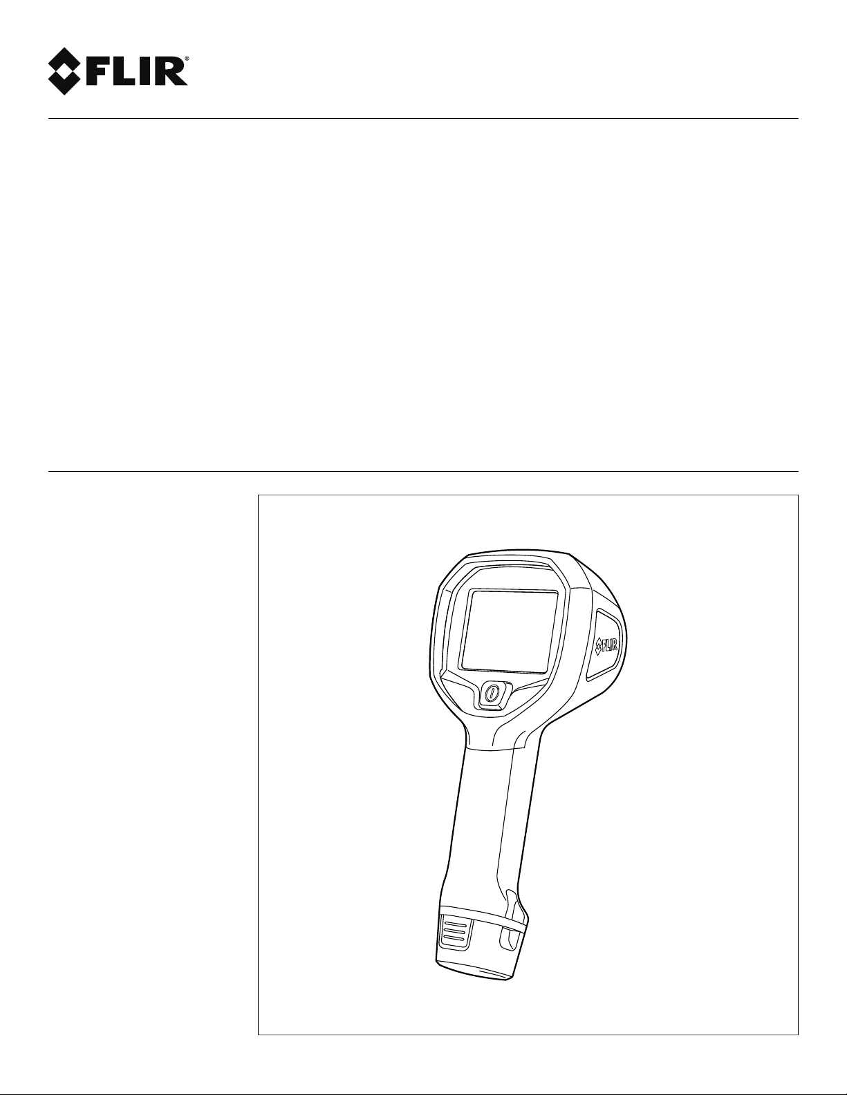
User’s manual
FLIR Kx series
Page 2

Page 3

Page 4

Important note
Before operating the device, you must read, understand, and follow all instructions, warnings, cautions, and legal disclaimers.
Důležitá poznámka
Před použitím zařízení si přečtěte veškeré pokyny, upozornění, varování a vyvázání se ze záruky, ujistěte se, že jim rozumíte, a řiďte se
jimi.
Vigtig meddelelse
Før du betjener enheden, skal du du læse, forstå og følge alle anvisninger, advarsler, sikkerhedsforanstaltninger og ansvarsfraskrivelser.
Wichtiger Hinweis
Bevor Sie das Gerät in Betrieb nehmen, lesen, verstehen und befolgen Sie unbedingt alle Anweisungen, Warnungen, Vorsichtshinweise
und Haftungsausschlüsse
Σημαντική σημείωση
Πριν από τη λειτουργία της συσκευής, πρέπει να διαβάσετε, να κατανοήσετε και να ακολουθήσετε όλες τις οδηγίες,
προειδοποιήσεις, προφυλάξεις και νομικές αποποιήσεις.
Nota importante
Antes de usar el dispositivo, debe leer, comprender y seguir toda la información sobre instrucciones, advertencias, precauciones y
renuncias de responsabilidad.
Tärkeä huomautus
Ennen laitteen käyttämistä on luettava ja ymmärrettävä kaikki ohjeet, vakavat varoitukset, varoitukset ja lakitiedotteet sekä noudatettava
niitä.
Remarque importante
Avant d'utiliser l'appareil, vous devez lire, comprendre et suivre l'ensemble des instructions, avertissements, mises en garde et clauses
légales de non-responsabilité.
Fontos megjegyzés
Az eszköz használata előtt figyelmesen olvassa el és tartsa be az összes utasítást, figyelmeztetést, óvintézkedést és jogi nyilatkozatot.
Nota importante
Prima di utilizzare il dispositivo, è importante leggere, capire e seguire tutte le istruzioni, avvertenze, precauzioni ed esclusioni di
responsabilità legali.
重要な注意
デバイスをご使用になる前に、あらゆる指示、警告、注意事項、および免責条項をお読み頂き、その内容を理解して従ってください。
중요한 참고 사항
장치를 작동하기 전에 반드시 다음의 사용 설명서와 경고, 주의사항, 법적 책임제한을 읽고 이해하며 따라야 합니다.
Viktig
Før du bruker enheten, må du lese, forstå og følge instruksjoner, advarsler og informasjon om ansvarsfraskrivelse.
Belangrijke opmerking
Zorg ervoor dat u, voordat u het apparaat gaat gebruiken, alle instructies, waarschuwingen en juridische informatie hebt doorgelezen en
begrepen, en dat u deze opvolgt en in acht neemt.
Ważna uwaga
Przed rozpoczęciem korzystania z urządzenia należy koniecznie zapoznać się z wszystkimi instrukcjami, ostrzeżeniami, przestrogami i
uwagami prawnymi. Należy zawsze postępować zgodnie z zaleceniami tam zawartymi.
Nota importante
Antes de utilizar o dispositivo, deverá proceder à leitura e compreensão de todos os avisos, precauções, instruções e isenções de
responsabilidade legal e assegurar-se do seu cumprimento.
Важное примечание
До того, как пользоваться устройством, вам необходимо прочитать и понять все предупреждения, предостережения и
юридические ограничения ответственности и следовать им.
Viktig information
Innan du använder enheten måste du läsa, förstå och följa alla anvisningar, varningar, försiktighetsåtgärder och ansvarsfriskrivningar.
Önemli not
Cihazı çalıştırmadan önce tüm talimatları, uyarıları, ikazları ve yasal açıklamaları okumalı, anlamalı ve bunlara uymalısınız.
重要注意事项
在操作设备之前,您必须阅读、理解并遵循所有说明、警告、注意事项和法律免责声明。
重要注意事項
操作裝置之前,您務必閱讀、了解並遵循所有說明、警告、注意事項與法律免責聲明。
Page 5

User’s manual
FLIR Kx series
#T559972; r. AG/39882/39882; en-US
v
Page 6

Page 7

Table of contents
1 Legal disclaimer ..................................................................................1
1.1 Legal disclaimer ............ .............. .............. .............. ... .............. .. 1
1.2 Usage statistics .............. ... ........... ... .............. .............. .............. . 1
1.3 Changes to registry .... ........... ... .............. ............................... ...... 1
1.4 U.S. Government Regulations.. .............. .............. .............. ............ 1
1.5 Copyright .... .............. .............. .............. .............. .............. ... .....1
1.6 Quality assurance . ... .............. .............. .............. .............. ...........1
1.7 Patents.......... .............. .............. ... ........... ... .............................. 1
1.8 EULA Terms ...................... .............. ... ........... ... .............. ...........1
2 Safety information ...............................................................................2
3 Notice to user .....................................................................................6
3.1 User-to-user forums ..... ... .............. .............. .............. .............. .... 6
3.2 Disposal of electronic waste ....... ... ................. .............. .............. ... 6
3.3 Training ...... ... ........... ... .............. .............. .............. ...................6
3.4 Documentation updates ............ .............. ............................... ...... 6
3.5 Important note about this manual...... .............. .............. ... .............. . 6
3.6 Note about authoritative versions.. .............. .............. .............. ........7
4 Customer help ....................................................................................8
4.1 General . .............. ............................... .............. ... .............. ....... 8
4.2 Submitting a question ................. .............. .............. .............. ... .... 8
4.3 Downloads . .............. .............. ... ........... ... ... .............. .............. ... 9
5 Important information about FLIR Kx series service .............................. 10
6 Introduction...................................................................................... 11
7 Quick start guide ............................................................................... 12
8 Camera parts .................................................................................... 13
8.1 View from the front ... .............. .............. .............. .............. ... ...... 13
8.1.1 Figure.. .............. .............. .............. .............. ... ............. 13
8.1.2 Explanation................. .............. ... .............. .............. ..... 13
8.2 View from the rear .............. .............. .............. ... .............. .......... 14
8.2.1 Figure.. .............. .............. .............. .............. ... ............. 14
8.2.2 Explanation................. .............. ... .............. .............. ..... 14
8.3 Lanyard strap........ ............................... ... ........... ... .............. ..... 15
9 Screen elements ............................................................................... 16
9.1 Figure ... .............. ............................................. .............. ... ..... 16
9.2 Explanation . .............. ... ........... ... .............. .............. ................. 16
10 Operation ......................................................................................... 17
10.1 Charging the battery........... .............. .............. .............. ... .......... 17
10.1.1 Charging the battery using the FLIR power supply ............. .... 17
10.1.2 Charging the battery using the FLIR stand-alone battery
10.1.3 Charging the battery using a USB cable ............ ... .............. . 18
10.2 Turning on and turning off the camera...................... .............. ........ 18
10.3 Accessing the connector bay.. ........... ... ................. .............. ........ 18
10.3.1 Procedure ...... ... .............. .............. .............. ................. 18
10.4 Changing temperature unit........ ... .............. .............. .............. ..... 19
10.4.1 General......... .............. .............. ............................... .... 19
10.4.2 Procedure ...... ... .............. .............. .............. ................. 19
10.5 Changing settings (in FLIR Tools) . .............. .............. .............. ...... 20
10.5.1 General......... .............. .............. ............................... .... 20
charger. ............ ... ........... ... .......................................... 17
#T559972; r. AG/39882/39882; en-US
vii
Page 8

Table of contents
10.5.2 The General settings tab ......... .............. .............. ............. 20
10.5.3 The User interface tab .. .............. .............. .............. ... ...... 21
10.5.4 Camera modes.. ... ... ........... ... .............. .............. ............ 21
10.6 Updating the camera ........... .............. .............. ... ........... ... ......... 26
10.6.1 General......... .............. .............. ............................... .... 26
11 Technical data................................................................................... 27
11.1 Online field-of-view calculator .......... .............. ... .............. ............. 27
11.2 Note about technical data ... .............. ... .............. ... .............. ........ 27
11.3 Note about authoritative versions.. .............. .............. .............. ...... 27
11.4 FLIR K2 ............ .............. .............. ................. ... ........... ... ........ 28
12 Mechanical drawings ......................................................................... 32
13 CE Declaration of conformity .............................................................. 37
14 Cleaning the camera .......................................................................... 39
14.1 Camera housing, cables, and other items.......... ... .............. ............ 39
14.1.1 Liquids............... ... ........... ... .............. .............. ............. 39
14.1.2 Equipment. .............. ............................... .............. ........ 39
14.1.3 Procedure ...... ... .............. .............. .............. ................. 39
14.2 Infrared lens .... .............. .............. ... ........... ... .............. ............. 39
14.2.1 Liquids............... ... ........... ... .............. .............. ............. 39
14.2.2 Equipment. .............. ............................... .............. ........ 39
14.2.3 Procedure ...... ... .............. .............. .............. ................. 39
15 About FLIR Systems .......................................................................... 40
15.1 More than just an infrared camera . .............. .............. .............. ..... 41
15.2 Sharing our knowledge .... .............. .............. .............. ... ........... .. 42
15.3 Supporting our customers ... .............. .......................................... 42
16 History of infrared technology............................................................. 43
#T559972; r. AG/39882/39882; en-US
viii
Page 9

1
Legal disclaimer
1.1 Legal disclaimer
All products manufactured by FLIR Systems are warranted against defective
materials and workmanship for a period of one (1) year from the delivery date
of the original purchase, provided such products have been under normal storage, use and service, and in accordance with FLIR Systems instruction.
Uncooled handheld infrared cameras manufactured by FLIR Systems are warranted against defective materials and workmanship for a period of two (2)
years from the delivery date of the original purchase, provided such products
have been under normal storage, use and ser vice, and in accordance with
FLIR Systems instruction, and provided that the camera has been registered
within 60 days of original purchase.
Detectors for uncooled handheld infrared cameras manufactured by FLIRSystems are warranted against defective materials and workmanship for a period
of ten (10) years from the delivery date of the original purchase, provided such
products have been under normal storage, use and serv ice, and in accordance
with FLIR Systems instruction, and provided that the camera has been registered within 60 days of original purchase.
Products which are not manufactured by FLIR Systems but included in systems delivered by FLIR Systems to the original purchaser, carry the warranty, if
any, of the particular supplier only. FLIR Systems has no responsibility whatsoever for such products.
The warranty extends only to the original purchaser and is not transferable. It
is not applicable to any product which has been subjected to misuse, neglect,
accident or abnormal conditions of operation. Expendable parts are excluded
from the warranty.
In the case of a defect in a product covered by this warranty the product must
not be further used in order to prevent additional damage. The purchaser shall
promptly report any defect to FLIR Systems or this warranty will not apply.
FLIR Systems will, at its option, repair or replace any such defective product
free of charge if, upon inspection, it proves to be defective in material or workmanship and provided that it is returned to FLIR Systems within the said oneyear period.
FLIR Systems has no other obligation or liability for defects than those set forth
above.
No other warranty is expressed or implied. FLIR Systems specifically disclaims
the implied warranties of merchantability and fitness for a particular purpose.
FLIR Systems shall not be liable forany direct, indirect, special, incidental or
consequential loss or damage, whether based oncontract, tort or any other legal theory.
This warranty shall be governed by Swedish law.
Any dispute, controversy or claim arisingout of or in connection with this warranty, shall be finally settled by arbitration in accordance with the Rulesof the
Arbitration Institute of the Stockholm Chamber of Commerce. The place of arbitration shall be Stockholm. The language to be used in the arbitral proceedings shall be English.
1.2 Usage statistics
FLIR Systems reserves the right to gather anonymous usage statistics to help
maintain and improve the quality of our software and services.
1.3 Changes to registry
The registry entry HKEY_LOCAL_MACHINE\SYSTEM\CurrentControlSet
\Control\Lsa\LmCompatibilityLevel will be automatically changed to level 2 if
the FLIR Camera Monitor service detects a FLIR camera connected to the
computer with a USB cable. The modification will only be executed if the camera device implements a remote network service that supports network logons.
1.4 U.S. Government Regulations
This product may be subject to U.S. Export Regulations. Please send any inquiries to exportquestions@flir.com.
1.5 Copyright
© 2016, FLIR Systems, Inc. All rights reserved worldwide. No parts of the software including source code may be reproduced, transmitted, transcribed or
translated into any language or computer languagein any form or by any
means, electronic, magnetic, optical, manual or otherwise, without theprior
written permission of FLIR Systems.
The documentation must not, in whole orpart, be copied, photocopied, reproduced, translated or transmitted toany electronic medium or machine readable form without prior consent, in writing, from FLIR Systems.
Names and marks appearing on the products herein are either registered
trademarks or trademarks of FLIR Systems and/or its subsidiaries. All other
trademarks, trade names or company names referenced herein areused for
identification only and are the property of their respective owners.
1.6 Quality assurance
The Quality Management System under which these products are developed
and manufactured has been certified in accordance with the ISO 9001
standard.
FLIR Systems is committed to a policyof continuous development; therefore
we reserve the right to make changes and improvements on any of theproducts without prior notice.
1.7 Patents
One or several of the following patents and/or design patents may apply to the
products and/or features. Additional pending patents and/or pending design
patents may also apply.
000279476-0001; 000439161; 000499579-0001; 000653423; 000726344;
000859020; 001106306-0001; 001707738; 001707746; 001707787;
001776519; 001954074; 002021543; 002058180; 002249953; 002531178;
0600574-8; 1144833; 1182246; 1182620; 1285345; 1299699; 1325808;
1336775; 1391114; 1402918; 1404291; 1411581; 1415075; 1421497;
1458284; 1678485; 1732314; 2106017; 2107799; 2381417; 3006596;
3006597; 466540; 483782; 484155; 4889913; 5177595; 60122153.2;
602004011681.5-08; 6707044; 68657; 7034300; 7110035; 7154093;
7157705; 7237946; 7312822; 7332716; 7336823; 7544944; 7667198;
7809258 B2; 7826736; 8,153,971; 8,823,803; 8,853,631; 8018649 B2;
8212210 B2; 8289372; 8354639 B2; 8384783; 8520970; 8565547; 8595689;
8599262; 8654239; 8680468; 8803093; D540838; D549758; D579475;
D584755; D599,392; D615,113; D664,580; D664,581; D665,004; D665,440;
D677298; D710,424 S; D718801; DI6702302-9; DI6903617-9; DI7002221-6;
DI7002891-5; DI7002892-3; DI7005799-0; DM/057692; DM/061609; EP
2115696 B1; EP2315433; SE 0700240-5; US 8340414 B2; ZL
201330267619.5; ZL01823221.3; ZL01823226.4; ZL02331553.9;
ZL02331554.7; ZL200480034894.0; ZL200530120994.2; ZL200610088759.5;
ZL200630130114.4; ZL200730151141.4; ZL200730339504.7;
ZL200820105768.8; ZL200830128581.2; ZL200880105236.4;
ZL200880105769.2; ZL200930190061.9; ZL201030176127.1;
ZL201030176130.3; ZL201030176157.2; ZL201030595931.3;
ZL201130442354.9; ZL201230471744.3; ZL201230620731.8.
1.8 EULA Terms
• Youhave acquired a device (“INFRARED CAMERA”) that includes software licensed by FLIR Systems AB from Microsoft Licensing, GP or its affiliates (“MS”). Those installed software products of MS origin, as well as
associated media, printed materials, and “online” orelectronic documentation (“SOFTWARE”) are protected by international intellectual property
laws and treaties. The SOFTWARE is licensed, not sold. All rights
reserved.
• IF YOU DO NOT AGREE TO THIS ENDUSER LICENSE AGREEMENT
(“EULA”), DO NOT USE THE DEVICE OR COPYTHE SOFTWARE. INSTEAD, PROMPTLYCONTACT FLIR Systems AB FOR INSTRUCTIONS
ON RETURN OF THE UNUSED DEVICE(S) FOR A REFUND. ANY USE
OF THE SOFTWARE, INCLUDING BUT NOT LIMITED TO USE ON
THE DEVICE, WILL CONSTITUTE YOUR AGREEMENT TO THIS EULA (OR RATIFICATION OF ANY PREVIOUS CONSENT).
• GRANT OF SOFTWARE LICENSE. This EULA grants you the following
license:
◦ Youmay use the SOFTWARE only on the DEVICE.
◦ NOT FAULT TOLERANT. THE SOFTWARE IS NOT FAULT TOLER-
ANT. FLIR Systems AB HAS INDEPENDENTLYDETERMINED
HOW TO USE THE SOFTWARE IN THE DEVICE, AND MS HAS
RELIED UPON FLIR Systems AB TO CONDUCT SUFFICIENT
TESTING TO DETERMINE THAT THE SOFTWARE IS SUITABLE
FOR SUCH USE.
◦ NO WARRANTIES FOR THE SOFTWARE. THE SOFTWARE is
provided “AS IS” and with all faults. THE ENTIRE RISK AS TO SATISFACTORY QUALITY, PERFORMANCE, ACCURACY, AND EFFORT (INCLUDING LACK OF NEGLIGENCE) IS WITH YOU.
ALSO, THERE IS NO WARRANTYAGAINST INTERFERENCE
WITH YOUR ENJOYMENT OF THE SOFTWARE OR AGAINST INFRINGEMENT. IF YOU HAVE RECEIVED ANY WARRANTIES RE-
GARDING THE DEVICE OR THE SOFTWARE, THOSE
WARRANTIES DO NOT ORIGINATE FROM, AND ARE NOT
BINDING ON, MS.
◦ No Liability for Certain Damages. EXCEPTAS PROHIBITED BY
LAW,MS SHALL HAVE NO LIABILITY FOR ANY INDIRECT, SPECIAL, CONSEQUENTIAL OR INCIDENTAL DAMAGES ARISING
FROM OR IN CONNECTION WITH THE USE OR PERFORMANCE OF THE SOFTWARE. THIS LIMITATION SHALL APPLY
EVEN IF ANY REMEDY FAILS OF ITS ESSENTIAL PURPOSE. IN
NO EVENT SHALL MS BE LIABLE FORANY AMOUNT INEXCESS OF U.S. TWO HUNDRED FIFTY DOLLARS (U.S.$250.00).
◦ Limitations on Reverse Engineering, Decompilation, and Dis-
assembly. Youmay not reverse engineer, decompile, or disassem-
ble the SOFTWARE, except and only to the extent that such activity
is expressly permitted by applicable law notwithstanding this
limitation.
◦ SOFTWARE TRANSFER ALLOWED BUT WITH RESTRICTIONS.
Youmay permanently transfer rights under this EULA only as part of
a permanent sale or transfer of the Device, and only if the recipient
agrees to this EULA. If the SOFTWARE is an upgrade, any transfer
must also include all prior versions of the SOFTWARE.
◦ EXPORT RESTRICTIONS. You acknowledge that SOFTWARE is
subject to U.S. export jurisdiction. You agree to comply with all applicable international and national laws that apply to the SOFTWARE,
including the U.S. Export Administration Regulations, as well as
end-user, end-use and destination restrictions issued by U.S. and
other governments. For additional information see http://www.microsoft.com/exporting/.
#T559972; r. AG/39882/39882; en-US
1
Page 10

2
Safety information
WARNING
Applicability: Cameras with one or more batteries.
Do not disassemble or do a modification to the battery. The battery contains safety and protection devices
which, if damage occurs, can cause the battery to become hot, or cause an explosion or an ignition.
WARNING
Applicability: Cameras with one or more batteries.
If there is a leak from the battery and you get the fluid in your eyes, do not rub your eyes. Flush well with
water and immediately get medical care. The battery fluid can cause injury to your eyes if you do not do
this.
WARNING
Applicability: Cameras with one or more batteries.
Do not continue to charge the battery if it does not become charged in the specified charging time. If you
continue to charge the battery, it can become hot and cause an explosion or ignition. Injury to persons
can occur.
WARNING
Applicability: Cameras with one or more batteries.
Only use the correct equipment to remove the electrical power from the battery. If you do not use the correct equipment, you can decrease the performance or the life cycle of the battery. If you do not use the
correct equipment, an incorrect flow of current to the battery can occur. This can cause the battery to become hot, or cause an explosion. Injury to persons can occur.
WARNING
Make sure that you read all applicable MSDS (Material Safety Data Sheets) and warning labels on containers before you use a liquid. The liquids can be dangerous. Injury to persons can occur.
CAUTION
Do not point the infrared camera (with or without the lens cover) at strong energy sources, for example,
devices that cause laser radiation, or the sun. This can have an unwanted effect on the accuracy of the
camera. It can also cause damage to the detector in the camera.
CAUTION
Applicability: Cameras with one or more batteries.
Do not attach the batteries directly to a car’s cigarette lighter socket, unless FLIR Systems supplies a specific adapter to connect the batteries to a cigarette lighter socket. Damage to the batteries can occur.
CAUTION
Applicability: Cameras with one or more batteries.
Do not connect the positive terminal and the negative terminal of the battery to each other with a metal
object (such as wire). Damage to the batteries can occur.
CAUTION
Applicability: Cameras with one or more batteries.
Do not get water or salt water on the battery, or permit the battery to become wet. Damage to the batteries
can occur.
#T559972; r. AG/39882/39882; en-US
2
Page 11

2
Safety information
CAUTION
Applicability: Cameras with one or more batteries.
Do not make holes in the battery with objects. Damage to the battery can occur.
CAUTION
Applicability: Cameras with one or more batteries.
Do not hit the battery with a hammer. Damage to the battery can occur.
CAUTION
Applicability: Cameras with one or more batteries.
Do not put your foot on the battery, hit it or cause shocks to it. Damage to the battery can occur.
CAUTION
Applicability: Cameras with one or more batteries.
Do not put the batteries in or near a fire, or into direct sunlight. When the battery becomes hot, the built-in
safety equipment becomes energized and can stop the battery charging procedure. If the battery becomes hot, damage can occur to the safety equipment and this can cause more heat, damage or ignition
of the battery.
CAUTION
Applicability: Cameras with one or more batteries.
Do not put the battery on a fire or increase the temperature of the battery with heat. Damage to the battery
and injury to persons can occur.
CAUTION
Applicability: Cameras with one or more batteries.
Do not put the battery on or near fires, stoves, or other high-temperature locations. Damage to the battery
and injury to persons can occur.
CAUTION
Applicability: Cameras with one or more batteries.
Do not solder directly onto the battery. Damage to the battery can occur.
CAUTION
Applicability: Cameras with one or more batteries.
Do not use the battery if, when you use, charge, or put the battery in storage, there is an unusual smell
from the battery, the battery feels hot, changes color, changes shape, or is in an unusual condition. Speak
with your sales office if one or more of these problems occurs. Damage to the battery and injury to persons can occur.
CAUTION
Applicability: Cameras with one or more batteries.
Only use a specified battery charger when you charge the battery. Damage to the battery can occur if you
do not do this.
#T559972; r. AG/39882/39882; en-US
3
Page 12

2
Safety information
CAUTION
Applicability: Cameras with one or more batteries.
Only use a specified battery for the camera. Damage to the camera and the battery can occur if you do
not do this.
CAUTION
Applicability: Cameras with one or more batteries.
The temperature range through which you can charge the battery is ±0°C to +45°C (+32°F to +113°F),
unless other information is specified in the user documentation or technical data. If you charge the battery
at temperatures out of this range, it can cause the battery to become hot or to break. It can also decrease
the performance or the life cycle of the battery.
CAUTION
Applicability: Cameras with one or more batteries.
The temperature range through which you can remove the electrical power from the battery is -15°C to
+50°C (+5°F to +122°F), unless other information is specified in the user documentation or technical data.
If you operate the battery out of this temperature range, it can decrease the performance or the life cycle
of the battery.
CAUTION
Applicability: Cameras with one or more batteries.
When the battery is worn, apply insulation to the terminals with adhesive tape or equivalent materials before you discard it. Damage to the battery and injury to persons can occur if you do not do this.
CAUTION
Applicability: Cameras with one or more batteries.
Remove any water or moisture on the battery before you install it. Damage to the battery can occur if you
do not do this.
CAUTION
Do not apply solvents or equivalent liquids to the camera, the cables, or other items. Damage to the battery and injury to persons can occur.
CAUTION
Be careful when you clean the infrared lens. The lens has an anti-reflective coating which is easily damaged. Damage to the infrared lens can occur.
CAUTION
Do not use too much force to clean the infrared lens. This can cause damage to the anti-reflective
coating.
Note The encapsulation rating is only applicable when all the openings on the camera
are sealed with their correct covers, hatches, or caps. This includes the compartments for
data storage, batteries, and connectors.
CAUTION
Do not change the standard fire-fighting procedures when you use a FLIR K series camera. The FLIR K
series camera is not a replacement technology.
#T559972; r. AG/39882/39882; en-US
4
Page 13

2
Safety information
CAUTION
Do not use the FLIR K series camera without the correct training. If the persons that operate the camera
do not have the correct training, an incorrect analysis of the infrared images can occur. Thus, incorrect
decisions during the firefighting can be made.
The training must include:
• How a thermal camera operates and its limits
• How to interpret an image
• How to work safely with the camera.
#T559972; r. AG/39882/39882; en-US
5
Page 14

3
Notice to user
3.1 User-to-user forums
Exchange ideas, problems, and infrared solutions with fellow thermographers around the
world in our user-to-user forums. To go to the forums, visit:
http://forum.infraredtraining.com/
3.2 Disposal of electronic waste
As with most electronic products, this equipment must be disposed of in an environmentally friendly way, and in accordance with existing regulations for electronic waste.
Please contact your FLIR Systems representative for more details.
3.3 Training
To read about infrared training, visit:
• http://www.infraredtraining.com
• http://www.irtraining.com
• http://www.irtraining.eu
3.4 Documentation updates
Our manuals are updated several times per year, and we also issue product-critical notifications of changes on a regular basis.
To access the latest manuals, translations of manuals, and notifications, go to the Download tab at:
http://support.flir.com
It only takes a few minutes to register online. In the download area you will also find the latest releases of manuals for our other products, as well as manuals for our historical and
obsolete products.
3.5 Important note about this manual
FLIR Systems issues generic manuals that cover several cameras within a model line.
This means that this manual may contain descriptions and explanations that do not apply
to your particular camera model.
#T559972; r. AG/39882/39882; en-US
6
Page 15

Notice to user3
3.6 Note about authoritative versions
The authoritative version of this publication is English. In the event of divergences due to
translation errors, the English text has precedence.
Any late changes are first implemented in English.
#T559972; r. AG/39882/39882; en-US
7
Page 16
4
Customer help
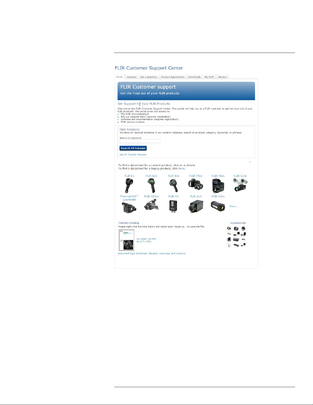
4.1 General
For customer help, visit:
http://support.flir.com
4.2 Submitting a question
To submit a question to the customer help team, you must be a registered user. It only
takes a few minutes to register online. If you only want to search the knowledgebase for
existing questions and answers, you do not need to be a registered user.
When you want to submit a question, make sure that you have the following information to
hand:
• The camera model
#T559972; r. AG/39882/39882; en-US
8
Page 17

4
Customer help
• The camera serial number
• The communication protocol, or method, between the camera and your device (for example, SD card reader, HDMI, Ethernet, USB, or FireWire)
• Device type (PC/Mac/iPhone/iPad/Android device, etc.)
• Version of any programs from FLIR Systems
• Full name, publication number, and revision number of the manual
4.3 Downloads
On the customer help site you can also download the following, when applicable for the
product:
• Firmware updates for your infrared camera.
• Program updates for your PC/Mac software.
• Freeware and evaluation versions of PC/Mac software.
• User documentation for current, obsolete, and historical products.
• Mechanical drawings (in *.dxf and *.pdf format).
• Cad data models (in *.stp format).
• Application stories.
• Technical datasheets.
• Product catalogs.
#T559972; r. AG/39882/39882; en-US
9
Page 18

5
Important information about FLIR Kx series service
• Contact the service department before shipping the camera. Many problems can be resolved on the phone—if so, the camera does not need to be shipped.
• The camera must be thoroughly cleaned, decontaminated and disinfected before shipping to our service department. No hazardous residues are allowed on cameras. Such
residues include—but are not limited to—chemical fire-extinguishing compounds, radioactivity, biohazardous materials, and residues from chemical fires.
• FLIR Systems reserves the right to charge the full cost for the decontamination and disinfection of contaminated cameras that are shipped to our service department.
#T559972; r. AG/39882/39882; en-US
10
Page 19

6
Introduction
Thank you for choosing a FLIR Kx series camera from FLIR Systems.
The FLIR Kx series is a robust and reliable infrared camera series designed to perform
under extremely severe conditions. The FLIR Kx series camera has an intuitive interface
with a design that makes it easy to control even with a gloved hand.
Main features:
• Robust and reliable. The FLIR Kx series is designed to meet tough operating conditions. It can withstand a drop from 2 m (6.5′) onto a concrete floor, is water resistant to
IP67, and is fully operational up to 55°C (135°F).
• Innovative. The FLIR Kx series utilizes our patented technology MSX, where a thermal
sensor is combined with a visual camera sensor to give detailed image information in
many user situations.
• Easy-to-use. The FLIR Kx series is easily used in a gloved professional hand. An intuitive and simple user interface allows you to focus on the job. The FLIR Kx series can be
controlled by just one large button on top of the unit.
#T559972; r. AG/39882/39882; en-US
11
Page 20

7
Quick start guide
Follow this procedure:
1. Charge the battery. You can do this in three different ways:
• Charge the battery using the FLIR stand-alone battery charger.
• Charge the battery using the FLIR power supply.
• Charge the battery using a USB cable connected to a computer.
Note Charging the camera using a USB cable connected to a computer takes
considerably longer than using the FLIR power supply or the FLIR stand-alone battery charger.
2. Push the on/off button to turn on the camera.
3. Aim the camera toward the object of interest.
#T559972; r. AG/39882/39882; en-US
12
Page 21

8
Camera parts
8.1 View from the front
8.1.1 Figure
8.1.2 Explanation
1. Digital camera lens.
2. Infrared lens.
3. Tripod mount.
4. Attachment point for lanyard strap.
#T559972; r. AG/39882/39882; en-US
13
Page 22

8
Camera parts
8.2 View from the rear
8.2.1 Figure
8.2.2 Explanation
1. Camera screen.
2. On/off button. This button has three functions:
• Push the on/off button to turn on the camera.
• Push and hold the on/off button for more than 3 seconds but less than 10 seconds
to put the camera into standby mode. The camera then automatically turns off after
6 hours.
• Push and hold the on/off button for more than 10 seconds to turn off the camera.
3. Battery.
#T559972; r. AG/39882/39882; en-US
14
Page 23

8
Camera parts
8.3 Lanyard strap
#T559972; r. AG/39882/39882; en-US
15
Page 24

9
Screen elements
9.1 Figure
9.2 Explanation
1. Low-sensitivity range indicator.
2. Overheating indicator. The indicator provides a visual warning to the user that the thermal imager is about to shut down due to internal overheating.
3. Temperature scale.
4. Digital readout of the temperature at the position of the spotmeter.
5. Battery status indicator.
6. Camera mode indicator (e.g. fire mode).
7. Spotmeter.
Note The icons are displayed in green or blue, depending on the selected camera mode.
• The green icon color indicates that the camera is in a mode where it automatically
switches between the high-sensitivity range and the low-sensitivity range, depending
on the temperature of objects in the field of view.
• The blue icon color indicates that the camera is in a mode where the temperature range
is locked to the high-sensitivity range.
#T559972; r. AG/39882/39882; en-US
16
Page 25

10
Operation
10.1 Charging the battery
10.1.1 Charging the battery using the FLIR power supply
Follow this procedure:
1. Connect the power supply to a wall outlet.
2. Connect the power supply cable to the USB connector on the camera. To access the
USB connector, see section 10.3 Accessing the connector bay, page 18.
Note The charging time for a fully depleted battery is 2 hours.
10.1.2 Charging the battery using the FLIR stand-alone battery charger.
Follow this procedure:
1. Connect the stand-alone battery charger to a wall outlet.
2. Remove the battery from the camera.
3. Put the battery into the stand-alone battery charger.
Note
• The charging time for a fully depleted battery is 2 hours.
• The battery is being charged when the blue LED is flashing.
• The battery is fully charged when the blue LED is continuous.
#T559972; r. AG/39882/39882; en-US
17
Page 26

10
Operation
10.1.3 Charging the battery using a USB cable
Follow this procedure:
1. Connect the camera to a computer using a USB cable. To access the USB connector,
see section 10.3 Accessing the connector bay, page 18.
Note
• To charge the camera, the computer must be turned on.
• Charging the camera using a USB cable connected to a computer takes considerably
longer than using the FLIR power supply or the FLIR stand-alone battery charger.
10.2 Turning on and turning off the camera
• Push the on/off button to turn on the camera.
• Push and hold the on/off button for more than 3 seconds but less than 10 seconds to
put the camera into standby mode. The camera then automatically turns off after 6
hours.
• Push and hold the on/off button for more than 10 seconds to turn off the camera.
10.3 Accessing the connector bay
10.3.1 Procedure
Follow this procedure:
1. Fold up the rubber cover at the top of the camera.
2. Hold the metal ring firmly.
#T559972; r. AG/39882/39882; en-US
18
Page 27

10
Operation
3. Turn the ring about 90° counter-clockwise.
4. Pull out the plastic insert.
CAUTION
The plastic insert has an O-ring seal. Do not damage the O-ring seal.
10.4 Changing temperature unit
10.4.1 General
The camera displays temperatures in ℃ or ℉. You change the temperature unit with a
switch, located in the connector bay.
10.4.2 Procedure
Follow this procedure:
1. To access the temperature unit switch, see section 10.3 Accessing the connector bay,
page 18.
2. Set the temperature unit switch to the desired position.
#T559972; r. AG/39882/39882; en-US
19
Page 28

10
Operation
10.5 Changing settings (in FLIR Tools)
10.5.1 General
By connecting the camera to FLIR Tools, you get access to a variety of settings in the
camera.
A download card for FLIR Tools is included in the transport case. Connect the camera to
the computer using the USB cable. To access the USB connector, see section 10.3 Ac-
cessing the connector bay, page 18.
10.5.2 The General settings tab
10.5.2.1 Figure
10.5.2.2 Explanation
Firmware info area: To check whether a newer version of the camera firmware exists, click
Check for updates, and follow the on-screen instructions.
Restore to factory default area: To restore all camera settings to the factory defaults, click
Restore.
#T559972; r. AG/39882/39882; en-US
20
Page 29

10
Operation
10.5.3 The User interface tab
10.5.3.1 Figure
10.5.3.2 Explanation
Camera modes area: To define which camera modes to enable in the camera, select the
camera mode. For more information on each camera mode, see section 10.5.4.2 Explana-
tion of the different camera modes, page 22.
Gain mode area:
• Auto gain mode: Select to make the camera automatically switch between the high-
sensitivity range and the low-sensitivity range, depending on the scene temperature.
The temperature level at which the camera switches between the two modes is +150°C
(+302°F).
• Low gain mode: Select to make the camera work in the low-sensitivity range only. This
has the advantage that the camera does not perform a non-uniformity correction when
an object with a temperature higher than +150°C (+302°F) enters the scene. However,
the disadvantage is lower sensitivity and a higher level of signal noise.
Add custom boot image area: To specify your own unique image to appear during start-up,
click Browse, and navigate to the image file. This is useful for, for example, identifying your
fire department’s cameras. By incorporating your fire department’s logo, and a unique
identity number in the image, you can keep track of your cameras.
10.5.4 Camera modes
10.5.4.1 General
The FLIR Kx series features seven different camera modes:
1. Basic mode.
2. Black and white firefighting mode.
#T559972; r. AG/39882/39882; en-US
21
Page 30

10
Operation
3. Fire mode.
4. Search and rescue mode.
5. Heat detection mode.
6. Cold detection mode.
7. Building analysis mode.
Each mode is optimized for a certain type of firefighting application. The modes also differ
in the following ways:
• Modes with green icons (1–3 in the list): The camera switches between the high-sensi-
tivity range (–20 to +150°C (–4 to +302°F)) and the low-sensitivity range (0 to +500°C
(+32 to +932°F)) automatically when an object with a temperature above 150°C (302°
F), covering more than 2% of the image, enters the field of view of the camera.
• Modes with blue icons (4–7 in the list): The temperature range is locked to the high-sen-
sitivity range (–20 to +150°C (–4 to +302°F)). This is useful if you need to maintain the
best possible image for objects with a temperature below 150°C (302°F), even if there
are objects with a temperature above 150°C (302°F) in the field of view of the camera.
10.5.4.2 Explanation of the different camera modes
10.5.4.2.1 Basic mode
Figure 10.1 Basic mode.
The Basic mode is the default mode of the camera. It is a multipurpose mode for the initial
fire attack with life rescuing operation and control of the fire. The camera automatically
switches between the high-sensitivity range and the low-sensitivity range, to maintain an
optimal infrared image while at the same time maintaining a safe and consistent heat colorization of the fire scene.
• Automatic range.
• Colorization of heat: +150 to +500°C (+302 to +932°F).
• High-sensitivity range: –20 to +150°C (–4 to +302°F).
• Low-sensitivity range: 0 to +500°C (+32 to +932°F).
#T559972; r. AG/39882/39882; en-US
22
Page 31

10
Operation
10.5.4.2.2 Black and white firefighting mode
Figure 10.2 Black and white firefighting mode.
The black and white firefighting mode is a standardized firefighting mode based on the Basic mode. It is a multipurpose mode for the initial fire intervention that includes life rescuing
operations and control of the fire. It is specifically designed for fire services that do not
want to use the heat colorization feature.
The camera automatically switches between the high-sensitivity range and the low-sensitivity range, to maintain an optimal infrared image.
• Automatic range.
• High-sensitivity range: –20 to +150°C (–4 to +302°F).
• Low-sensitivity range: 0 to +500°C (+32 to +932°F).
10.5.4.2.3 Fire mode
Figure 10.3 Fire mode.
The fire mode is similar to the Basic mode, but with a higher-temperature starting point for
the heat colorization. It is suitable for fire scenes with higher background temperatures,
where there are already a lot of open flames and a high background temperature. The
camera automatically switches between the high-sensitivity range and the low-sensitivity
range, to maintain an optimal infrared image while at the same time maintaining a safe
and consistent heat colorization.
• Automatic range.
#T559972; r. AG/39882/39882; en-US
23
Page 32

10
Operation
• Colorization of heat: +250 to +500°C (+ 482 to +932°F).
• High-sensitivity range: –20 to +150°C (–4 to +302°F).
• Low-sensitivity range: 0 to +500°C (+32 to +932°F).
10.5.4.2.4 Search and rescue mode
Figure 10.4 Search and rescue mode.
The search and rescue mode is optimized for maintaining high contrast in the infrared image while searching for people in landscapes, buildings, or traffic accident scenes.
• High-sensitivity range only.
• Colorization of heat: +100 to +150°C (+212 to +302°F).
• High-sensitivity range: –20 to +150°C (–4 to +302°F).
10.5.4.2.5 Heat detection mode
Figure 10.5 Heat detection mode.
The heat detection mode is optimized for searching hotspots during overhaul after the fire
is out—typically to ensure that there is no remaining hidden fire. This mode can also be
used to find thermal patterns (e.g., signs of people in car seats after accidents), to ensure
that everyone has been found. This mode can also be used to search for people in water
and open landscapes.
• High-sensitivity range only.
• Colorization of heat: the 20% highest temperatures in the scene.
#T559972; r. AG/39882/39882; en-US
24
Page 33

10
Operation
• High-sensitivity range: –20 to +150°C (–4 to +302°F).
10.5.4.2.6 Cold detection mode
Figure 10.6 Cold detection mode.
The cold detection mode is optimized for searching coldspots—typically to find drafts and
air flows.
• High-sensitivity range only.
• Colorization of cold: the 20% lowest temperatures in the scene.
• High-sensitivity range: –20 to +150°C (–4 to +302°F).
10.5.4.2.7 Building analysis mode
Figure 10.7 Building analysis mode.
The building analysis mode is suitable for the analysis of buildings and the detection of
building-related anomalies. The thermal image can provide information on structural, mechanical, plumbing, and electrical constructions as well as an indication of moisture, wetness, and air infiltration.
In this mode, the camera uses an iron color palette to display the different temperatures,
where black, blue, and purple are for the coldest areas, followed by red, orange, and yellow for the mid-range and going to white for the hottest parts. The temperature scale is automatically adjusted to the thermal content of the image.
#T559972; r. AG/39882/39882; en-US
25
Page 34

10
Operation
10.6 Updating the camera
10.6.1 General
To take advantage of the latest FLIR camera firmware, it is important that you keep your
camera updated. You update your camera using FLIR Tools, see section 10.5 Changing
settings (in FLIR Tools), page 20.
#T559972; r. AG/39882/39882; en-US
26
Page 35

11
Technical data
Table of contents
11.1 Online field-of-view calculator............................................................. 27
11.2 Note about technical data................................................................... 27
11.3 Note about authoritative versions........................................................ 27
11.4 FLIR K2 ............................................................................................ 28
11.1 Online field-of-view calculator
Please visit http://support.flir.com and click the photo of the camera series for field-of-view
tables for all lens–camera combinations.
11.2 Note about technical data
FLIR Systems reserves the right to change specifications at any time without prior notice.
Please check http://support.flir.com for latest changes.
11.3 Note about authoritative versions
The authoritative version of this publication is English. In the event of divergences due to
translation errors, the English text has precedence.
Any late changes are first implemented in English.
#T559972; r. AG/39882/39882; en-US
27
Page 36

Technical data11
11.4 FLIR K2
P/N: 73701-0101
Rev.: 39875
General description
The FLIR K2 is a robust and reliable infrared camera designed to perform under extremely severe conditions. The FLIR K2 has an intuitive interface with a design that makes it easy to control even with a gloved
hand.
Benefits:
• Robust and reliable: The FLIR K2 is designed to meet tough operating conditions. It can withstand a
drop from 2 m (6.5 ft.), is water resistant to IP67, and is fully operational up to 55°C (135°F), and operational up to +85°C (+185°F) for 15 minutes, +150°C (+302°F) for 10 minutes, and +260°C (+500°
F) for 3 minutes.
• Innovative: The FLIR K2 utilizes our patented technology MSX, where a thermal sensor is combined
with a visual camera sensor to give detailed image information in many user situations.
• Easy-to-use: Easily used in a gloved professional hand. An intuitive and simple user interface allows
you to focus on the job. The FLIR K2 can be controlled by just one large button on top of the unit.
Typical applications:
• Heat detection.
• Search and rescue.
• Final extinction.
• Back-up camera.
• Scanning camera.
• Fire attack.
Imaging and optical data
IR resolution 160 × 120 pixels
Thermal sensitivity/NETD < 100 mK @ +30°C (+86°F)
Field of view (FOV)
Depth of field 0.1 m (0.33 ft.), infinity
Focal length 1.9 mm (0.075 in.)
Spatial resolution (IFOV)
F-number 1.1
Image frequency 9 Hz
Focus Fixed
Detector data
Detector type Focal plane array, uncooled microbolometer
Spectral range
Pitch 12 μm
Visual camera
Built-in digital camera 640 × 480 pixels
Digital camera, FOV 73° × 61°, adapts to the IR lens
Sensitivity Minimum 10 lux
47° × 35°
6.22 mrad
7.5–13 µm
#T559972; r. AG/39882/39882; en-US
28
Page 37

Technical data11
Image presentation
Display 3 in. LCD, 320 × 240 pixels, backlit
Auto range Auto, non-selectable
Image presentation modes
Image modes
Multi Spectral Dynamic Imaging (MSX) Yes
• Basic fire-fighting mode (default)
• Black-and-white fire-fighting mode
• Fire mode
• Search-and-rescue mode
• Heat detection mode
• Cold detection mode
• Building analysis mode
NOTE
The image mode can only be changed using
FLIR Tools.
Measurement
Object temperature range
Accuracy
Measurement analysis
Spotmeter
Automatic hot detection Heat detection mode (the hottest 20% of the of
Isotherm Yes
USB
USB USB Micro-B
Compatibility
Compatible with FLIR software
Data communication interfaces
Interfaces Update from PC devices
Power system
Battery type Li ion
Battery voltage 3.6 V
Battery capacity
Battery operating time
Charging system
Charging time 2.5 h to 90% capacity, charging status indicated by
Charging temperature 0–45°C (32–113°F)
Power management Automatic shutdown and sleep mode
• –20°C to +150°C (–4°F to +302°F)
• 0°C to +500°C (+32°F to +932°F)
±4°C (±7.2°F) or ±4% for ambient temperatures of
10–35°C (50–95°F)
1
scene is colorized)
FLIR Tools
2.6 Ah at 20–25°C (68–77°F)
Approximately 4 hours at +25°C (+77°F) ambient
temperature and typical use
Battery is charged inside the camera or in a dedicated charger
LEDs
#T559972; r. AG/39882/39882; en-US
29
Page 38

Technical data11
Power system
Start-up time from sleep mode
Start-up time
Environmental data
Operating temperature range
Storage temperature range –40°C to +70°C (–40°F to +158°F)
Humidity (operating and storage) IEC 60068-2-30, 24 hours, 95% relative humidity,
Relative humidity 95% relative humidity, 25–40°C (77–104°F), non-
EMC
Magnetic fields EN 61 000-4-8, test level 5 for continuous field (se-
Encapsulation IP 67 (IEC 60529)
Corrosion ASTM B117, salt spray, 5% saline solution in 48
Shock 25 g (IEC 60068-2-27)
Vibration
Drop 2 m (6.6 ft.)
Safety (power supply) CE/EN/UL/CSA/PSE 60950-1
10 seconds
30 seconds
• –10°C to +55°C (+14°F to +131°F): infinity
• +85°C (+185°F): 15 minutes
• +150°C (+302°F): 10 minutes
• +260°C (+500°F): 3 minutes
25–40°C (77–104°F), 2 cycles
condensing
• EN 61000-6-2:2005 (immunity)
• EN 61000-6-3:2011 (emission)
• FCC 47 CFR Part 15 B (emission)
vere industrial environment)
hours and +35°C
2 g (IEC 60068-2-6)
Physical data
Camera weight, incl. battery 0.7 kg (1.54 lb.)
Battery weight 0.119 kg (0.26 lb.)
Camera size (L × W × H) 250 mm × 105 mm × 90 mm (9.8 in. × 4.1 in. × 3.5
Tripod mounting
Material
Shipping information
List of contents
Packaging, weight
in.)
UNC ¼″-20
• PPSU
• Silicon rubber
• Aluminium, cast
• Flame-resistant magnesium alloy
• Infrared camera
• Battery (×2)
• Battery charger
• Lanyard strap
• Power supply
• Printed documentation
• USB cable
• 1-pack: 2.06 kg (4.5 lb.)
• 5-pack: 11.2 kg (24.7 lb.)
#T559972; r. AG/39882/39882; en-US
30
Page 39

Technical data11
Shipping information
Packaging, size
EAN-13 4743254002050
UPC-12
Country of origin
• 1-pack: 323 × 325 × 110 mm (12.7 × 12.8 × 4.3
in.)
• 5-pack: 578 × 336 × 351 mm (22.93 × 13.10 ×
13.68 in.)
845188011345
Estonia
Supplies & accessories:
• T198532; Car charger
• T198533; USB cable Std A <-> Micro B
• T127722ACC; Retractable lanyard
• T199127; Li-Ion Battery pack 3.6 V 2.6 Ah
• T199128; Battery charger, incl. power supply with multi plugs
• T199423ACC; Battery Li-ion 3.6 V, 2.6 Ah, 9.4 Wh
• T199414; In-truck charger
• T199130; Lanyard strap
• T199357; Hard transport case
#T559972; r. AG/39882/39882; en-US
31
Page 40

12
Mechanical drawings
#T559972; r. AG/39882/39882; en-US
32
Page 41

Page 42

Page 43

Page 44

Page 45

13
CE Declaration of conformity
#T559972; r. AG/39882/39882; en-US
37
Page 46

Page 47

14
Cleaning the camera
14.1 Camera housing, cables, and other items
14.1.1 Liquids
Use one of these liquids:
• Warm water
• A weak detergent solution
14.1.2 Equipment
A soft cloth
14.1.3 Procedure
Follow this procedure:
1. Soak the cloth in the liquid.
2. Twist the cloth to remove excess liquid.
3. Clean the part with the cloth.
CAUTION
Do not apply solvents or similar liquids to the camera, the cables, or other items. This can cause damage.
14.2 Infrared lens
14.2.1 Liquids
Use one of these liquids:
• A commercial lens cleaning liquid with more than 30% isopropyl alcohol.
• 96% ethyl alcohol (C
14.2.2 Equipment
Cotton wool
14.2.3 Procedure
Follow this procedure:
1. Soak the cotton wool in the liquid.
2. Twist the cotton wool to remove excess liquid.
3. Clean the lens one time only and discard the cotton wool.
WARNING
Make sure that you read all applicable MSDS (Material Safety Data Sheets) and warning labels on containers before you use a liquid: the liquids can be dangerous.
2H5
OH).
CAUTION
• Be careful when you clean the infrared lens. The lens has a delicate anti-reflective coating.
• Do not clean the infrared lens too vigorously. This can damage the anti-reflective coating.
#T559972; r. AG/39882/39882; en-US
39
Page 48

15
About FLIR Systems
FLIR Systems was established in 1978 to pioneer the development of high-performance
infrared imaging systems, and is the world leader in the design, manufacture, and marketing of thermal imaging systems for a wide variety of commercial, industrial, and government applications. Today, FLIR Systems embraces five major companies with outstanding
achievements in infrared technology since 1958—the Swedish AGEMA Infrared Systems
(formerly AGA Infrared Systems), the three United States companies Indigo Systems, FSI,
and Inframetrics, and the French company Cedip.
Since 2007, FLIR Systems has acquired several companies with world-leading expertise
in sensor technologies:
• Extech Instruments (2007)
• Ifara Tecnologías (2008)
• Salvador Imaging (2009)
• OmniTech Partners (2009)
• Directed Perception (2009)
• Raymarine (2010)
• ICx Technologies (2010)
• TackTick Marine Digital Instruments (2011)
• Aerius Photonics (2011)
• Lorex Technology (2012)
• Traficon (2012)
• MARSS (2013)
• DigitalOptics micro-optics business (2013)
• DVTEL (2015)
• Point Grey Research (2016)
• Prox Dynamics (2016)
Figure 15.1 Patent documents from the early 1960s
FLIR Systems has three manufacturing plants in the United States (Portland, OR, Boston,
MA, Santa Barbara, CA) and one in Sweden (Stockholm). Since 2007 there is also a
#T559972; r. AG/39882/39882; en-US
40
Page 49

15
About FLIR Systems
manufacturing plant in Tallinn, Estonia. Direct sales offices in Belgium, Brazil, China,
France, Germany, Great Britain, Hong Kong, Italy, Japan, Korea, Sweden, and the USA—
together with a worldwide network of agents and distributors—support our international
customer base.
FLIR Systems is at the forefront of innovation in the infrared camera industry. We anticipate market demand by constantly improving our existing cameras and developing new
ones. The company has set milestones in product design and development such as the introduction of the first battery-operated portable camera for industrial inspections, and the
first uncooled infrared camera, to mention just two innovations.
Figure 15.2 1969: Thermovision Model 661. The
camera weighed approximately 25 kg (55 lb.), the
oscilloscope 20 kg (44 lb.), and the tripod 15 kg
(33 lb.). The operator also needed a 220 VAC generator set, and a 10 L (2.6 US gallon) jar with liquid
nitrogen. To the left of the oscilloscope the Polaroid
attachment (6 kg/13 lb.) can be seen.
Figure 15.3 2015: FLIR One, an accessory to
iPhone and Android mobile phones. Weight: 90 g
(3.2 oz.).
FLIR Systems manufactures all vital mechanical and electronic components of the camera
systems itself. From detector design and manufacturing, to lenses and system electronics,
to final testing and calibration, all production steps are carried out and supervised by our
own engineers. The in-depth expertise of these infrared specialists ensures the accuracy
and reliability of all vital components that are assembled into your infrared camera.
15.1 More than just an infrared camera
At FLIR Systems we recognize that our job is to go beyond just producing the best infrared
camera systems. We are committed to enabling all users of our infrared camera systems
to work more productively by providing them with the most powerful camera–software
combination. Especially tailored software for predictive maintenance, R & D, and process
monitoring is developed in-house. Most software is available in a wide variety of
languages.
We support all our infrared cameras with a wide variety of accessories to adapt your equipment to the most demanding infrared applications.
#T559972; r. AG/39882/39882; en-US
41
Page 50

15
About FLIR Systems
15.2 Sharing our knowledge
Although our cameras are designed to be very user-friendly, there is a lot more to thermography than just knowing how to handle a camera. Therefore, FLIR Systems has founded
the Infrared Training Center (ITC), a separate business unit, that provides certified training
courses. Attending one of the ITC courses will give you a truly hands-on learning
experience.
The staff of the ITC are also there to provide you with any application support you may
need in putting infrared theory into practice.
15.3 Supporting our customers
FLIR Systems operates a worldwide service network to keep your camera running at all
times. If you discover a problem with your camera, local service centers have all the equipment and expertise to solve it within the shortest possible time. Therefore, there is no need
to send your camera to the other side of the world or to talk to someone who does not
speak your language.
#T559972; r. AG/39882/39882; en-US
42
Page 51

16
History of infrared technology
Before the year 1800, the existence of the infrared portion of the electromagnetic spectrum
wasn't even suspected. The original significance of the infrared spectrum, or simply ‘the infrared’ as it is often called, as a form of heat radiation is perhaps less obvious today than it
was at the time of its discovery by Herschel in 1800.
Figure 16.1 Sir William Herschel (1738–1822)
The discovery was made accidentally during the search for a new optical material. Sir William Herschel – Royal Astronomer to King George III of England, and already famous for
his discovery of the planet Uranus – was searching for an optical filter material to reduce
the brightness of the sun’s image in telescopes during solar observations. While testing
different samples of colored glass which gave similar reductions in brightness he was intrigued to find that some of the samples passed very little of the sun’s heat, while others
passed so much heat that he risked eye damage after only a few seconds’ observation.
Herschel was soon convinced of the necessity of setting up a systematic experiment, with
the objective of finding a single material that would give the desired reduction in brightness
as well as the maximum reduction in heat. He began the experiment by actually repeating
Newton’s prism experiment, but looking for the heating effect rather than the visual distribution of intensity in the spectrum. He first blackened the bulb of a sensitive mercury-inglass thermometer with ink, and with this as his radiation detector he proceeded to test
the heating effect of the various colors of the spectrum formed on the top of a table by
passing sunlight through a glass prism. Other thermometers, placed outside the sun’s
rays, served as controls.
As the blackened thermometer was moved slowly along the colors of the spectrum, the
temperature readings showed a steady increase from the violet end to the red end. This
was not entirely unexpected, since the Italian researcher, Landriani, in a similar experiment
in 1777 had observed much the same effect. It was Herschel, however, who was the first
to recognize that there must be a point where the heating effect reaches a maximum, and
that measurements confined to the visible portion of the spectrum failed to locate this
point.
Figure 16.2 Marsilio Landriani (1746–1815)
#T559972; r. AG/39882/39882; en-US
43
Page 52

16
History of infrared technology
Moving the thermometer into the dark region beyond the red end of the spectrum, Herschel confirmed that the heating continued to increase. The maximum point, when he
found it, lay well beyond the red end – in what is known today as the ‘infrared wavelengths’.
When Herschel revealed his discovery, he referred to this new portion of the electromagnetic spectrum as the ‘thermometrical spectrum’. The radiation itself he sometimes referred to as ‘dark heat’, or simply ‘the invisible rays’. Ironically, and contrary to popular
opinion, it wasn't Herschel who originated the term ‘infrared’. The word only began to appear in print around 75 years later, and it is still unclear who should receive credit as the
originator.
Herschel’s use of glass in the prism of his original experiment led to some early controversies with his contemporaries about the actual existence of the infrared wavelengths. Different investigators, in attempting to confirm his work, used various types of glass
indiscriminately, having different transparencies in the infrared. Through his later experiments, Herschel was aware of the limited transparency of glass to the newly-discovered
thermal radiation, and he was forced to conclude that optics for the infrared would probably be doomed to the use of reflective elements exclusively (i.e. plane and curved mirrors). Fortunately, this proved to be true only until 1830, when the Italian investigator,
Melloni, made his great discovery that naturally occurring rock salt (NaCl) – which was
available in large enough natural crystals to be made into lenses and prisms – is remarkably transparent to the infrared. The result was that rock salt became the principal infrared
optical material, and remained so for the next hundred years, until the art of synthetic crystal growing was mastered in the 1930’s.
Figure 16.3 Macedonio Melloni (1798–1854)
Thermometers, as radiation detectors, remained unchallenged until 1829, the year Nobili
invented the thermocouple. (Herschel’s own thermometer could be read to 0.2 °C (0.036 °
F), and later models were able to be read to 0.05 °C (0.09 °F)). Then a breakthrough occurred; Melloni connected a number of thermocouples in series to form the first thermopile.
The new device was at least 40 times as sensitive as the best thermometer of the day for
detecting heat radiation – capable of detecting the heat from a person standing three meters away.
The first so-called ‘heat-picture’ became possible in 1840, the result of work by Sir John
Herschel, son of the discoverer of the infrared and a famous astronomer in his own right.
Based upon the differential evaporation of a thin film of oil when exposed to a heat pattern
focused upon it, the thermal image could be seen by reflected light where the interference
effects of the oil film made the image visible to the eye. Sir John also managed to obtain a
primitive record of the thermal image on paper, which he called a ‘thermograph’.
#T559972; r. AG/39882/39882; en-US
44
Page 53

16
History of infrared technology
Figure 16.4 Samuel P. Langley (1834–1906)
The improvement of infrared-detector sensitivity progressed slowly. Another major breakthrough, made by Langley in 1880, was the invention of the bolometer. This consisted of a
thin blackened strip of platinum connected in one arm of a Wheatstone bridge circuit upon
which the infrared radiation was focused and to which a sensitive galvanometer responded. This instrument is said to have been able to detect the heat from a cow at a distance of 400 meters.
An English scientist, Sir James Dewar, first introduced the use of liquefied gases as cooling agents (such as liquid nitrogen with a temperature of -196 °C (-320.8 °F)) in low temperature research. In 1892 he invented a unique vacuum insulating container in which it is
possible to store liquefied gases for entire days. The common ‘thermos bottle’, used for
storing hot and cold drinks, is based upon his invention.
Between the years 1900 and 1920, the inventors of the world ‘discovered’ the infrared.
Many patents were issued for devices to detect personnel, artillery, aircraft, ships – and
even icebergs. The first operating systems, in the modern sense, began to be developed
during the 1914–18 war, when both sides had research programs devoted to the military
exploitation of the infrared. These programs included experimental systems for enemy intrusion/detection, remote temperature sensing, secure communications, and ‘flying torpedo’ guidance. An infrared search system tested during this period was able to detect an
approaching airplane at a distance of 1.5 km (0.94 miles), or a person more than 300 meters (984 ft.) away.
The most sensitive systems up to this time were all based upon variations of the bolometer
idea, but the period between the two wars saw the development of two revolutionary new
infrared detectors: the image converter and the photon detector. At first, the image converter received the greatest attention by the military, because it enabled an observer for
the first time in history to literally ‘see in the dark’. However, the sensitivity of the image
converter was limited to the near infrared wavelengths, and the most interesting military
targets (i.e. enemy soldiers) had to be illuminated by infrared search beams. Since this involved the risk of giving away the observer’s position to a similarly-equipped enemy observer, it is understandable that military interest in the image converter eventually faded.
The tactical military disadvantages of so-called 'active’ (i.e. search beam-equipped) thermal imaging systems provided impetus following the 1939–45 war for extensive secret
military infrared-research programs into the possibilities of developing ‘passive’ (no search
beam) systems around the extremely sensitive photon detector. During this period, military
secrecy regulations completely prevented disclosure of the status of infrared-imaging
technology. This secrecy only began to be lifted in the middle of the 1950’s, and from that
time adequate thermal-imaging devices finally began to be available to civilian science
and industry.
#T559972; r. AG/39882/39882; en-US
45
Page 54

A note on the technical production of this publication
This publication was produced using XML — the eXtensible Markup Language. For more information about
XML, please visit http://www.w3.org/XML/
A note on the typeface used in this publication
This publication was typeset using Linotype Helvetica™ World. Helvetica™ was designed by Max Miedinger
(1910–1980)
LOEF (List Of Effective Files)
T501132.xml; en-US; AG; 39882; 2017-01-31
T505471.xml; en-US; 9229; 2013-10-03
T505845.xml; en-US; 39865; 2017-01-31
T505846.xml; en-US; 39792; 2017-01-30
T505013.xml; en-US; 39689; 2017-01-25
T505691.xml; en-US; 39865; 2017-01-31
T505847.xml; en-US; 39865; 2017-01-31
T505848.xml; en-US; 39865; 2017-01-31
T505850.xml; en-US; 39865; 2017-01-31
T505851.xml; en-US; 39865; 2017-01-31
T505852.xml; en-US; 39865; 2017-01-31
T505854.xml; en-US; 39880; 2017-01-31
T505470.xml; en-US; 39513; 2017-01-18
T505007.xml; en-US; 39512; 2017-01-18
T505005.xml; en-US; 39512; 2017-01-18
#T559972; r. AG/39882/39882; en-US
46
Page 55

Page 56

Website
last page
http://www.flir.com
Customer support
http://support.flir.com
Copyright
© 2017, FLIR Systems, Inc. All rights reserved worldwide.
Disclaimer
Specifications subject to change without further notice. Models and accessories subject to regional market considerations. License procedures may apply. Products
described herein may be subject to US Export Regulations. Please refer to exportquestions@flir.com with any questions.
Publ. No.: T559972
Release: AG
Commit:
Head: 39882
Language: en-US
Modified: 2017-01-31
Formatted: 2017-01-31
39882
 Loading...