

Page 1
User’s manual
FLIR bXX series
FLIR iXX series
T559059Publ. No.
a460Revision
English (EN)Language
July 1, 2010Issue date
Page 2

Page 3

User’s manual
Publ. No. T559059 Rev. a460 – ENGLISH (EN) – July 1, 2010
Page 4

Legal disclaimer
All products manufactured by FLIR Systemsarewarranted against defectivematerialsandworkmanship for aperiodof one(1)year from the
delivery date of the original purchase, provided such products have been under normal storage, use and service, and in accordance with
FLIR Systems instruction.
Products which are not manufactured by FLIR Systems but included in systems delivered by FLIR Systems to the original purchaser, carry
the warranty, if any, of the particular supplier only. FLIR Systems has no responsibility whatsoever for such products.
The warranty extends only to the original purchaser and is not transferable. It is not applicable to any product which has been subjected to
misuse, neglect, accident or abnormal conditions of operation. Expendable parts are excluded from the warranty.
In the case of adefect inaproduct coveredbythis warrantytheproduct must notbe furtherusedin order toprevent additional damage.The
purchaser shall promptly report any defect to FLIR Systems or this warranty will not apply.
FLIR Systems will, at its option, repair or replace any such defective product free of charge if, upon inspection, it proves to be defective in
material or workmanship and provided that it is returned to FLIR Systems within the said one-year period.
FLIR Systems has no other obligation or liability for defects than those set forth above.
No other warranty is expressed or implied. FLIR Systems specifically disclaims the implied warranties of merchantability and fitness for a
particular purpose.
FLIR Systems shall not be liable for any direct, indirect, special, incidentalor consequential loss or damage, whether basedon contract, tort
or any other legal theory.
This warranty shall be governed by Swedish law.
Any dispute, controversy or claim arising out of or in connection with this warranty, shall be finally settled by arbitration in accordance with
the Rules of the Arbitration Institute of the Stockholm Chamber of Commerce. The place of arbitration shall be Stockholm. The language to
be used in the arbitral proceedings shall be English.
Copyright
© 2010, FLIRSystems. All rights reservedworldwide. No parts ofthesoftware including source codemaybe reproduced, transmitted, transcribed
or translated into any language or computer language in any form or by any means, electronic, magnetic, optical, manual or otherwise,
without the prior written permission of FLIR Systems.
This documentation must not, in whole or part, be copied, photocopied, reproduced, translated or transmitted to any electronic medium or
machine readable form without prior consent, in writing, from FLIR Systems.
Names and marks appearing on the products herein are eitherregistered trademarksor trademarksof FLIR Systems and/or its subsidiaries.
All othertrademarks,trade names or companynames referenced herein areusedfor identification only andarethe property of theirrespective
owners.
Quality assurance
The Quality Management System under which these products are developed and manufactured has been certified in accordance with the
ISO 9001 standard.
FLIR Systems is committed to a policy of continuous development; therefore we reserve the right to make changes and improvements on
any of the products described in this manual without prior notice.
Patents
One or several of the following patents or design patents apply to the products and/or features described in this manual:
0002258-2; 000279476-0001; 000439161; 000499579-0001; 000653423; 000726344; 000859020; 000889290; 001106306-0001; 0101577-5;
0102150-0; 0200629-4; 0300911-5; 0302837-0; 1144833; 1182246; 1182620; 1188086; 1263438; 1285345; 1287138; 1299699; 1325808;
1336775; 1365299; 1678485; 1732314; 200530018812.0; 200830143636.7; 2106017; 235308; 3006596; 3006597; 466540; 483782; 484155;
518836; 60004227.8;60122153.2;602004011681.5-08; 6707044; 68657; 7034300;7110035;7154093; 7157705; 7237946; 7312822;7332716;
7336823; 7544944; 75530; D540838; D549758; D579475; D584755; D599,392; DI6702302-9; DI6703574-4; DM/057692; DM/061609;
ZL00809178.1; ZL01823221.3; ZL01823226.4; ZL02331553.9; ZL02331554.7; ZL200530120994.2; ZL200630130114.4; ZL200730151141.4;
ZL200730339504.7; ZL200830128581.2
EULA Terms
You have acquired a device (“INFRARED CAMERA”) that includes software licensed by FLIR Systems AB from Microsoft Licensing, GP
■
or its affiliates (“MS”). Those installed software products of MS origin, as well as associated media, printed materials, and “online” or
electronic documentation(“SOFTWARE”)are protected by internationalintellectualproperty laws and treaties.TheSOFTWARE is licensed,
not sold. All rights reserved.
IF YOU DO NOTAGREE TO THISENDUSER LICENSE AGREEMENT(“EULA”), DONOT USE THEDEVICEOR COPY THE SOFTWARE.
■
INSTEAD, PROMPTLY CONTACT FLIR Systems AB FOR INSTRUCTIONS ON RETURN OF THE UNUSED DEVICE(S) FOR A REFUND.
ANY USE OF THE SOFTWARE, INCLUDING BUT NOT LIMITED TO USE ON THE DEVICE, WILL CONSTITUTE YOUR AGREEMENT
TO THIS EULA (OR RATIFICATION OF ANY PREVIOUS CONSENT).
GRANT OF SOFTWARE LICENSE. This EULA grants you the following license:
■
You may use the SOFTWARE only on the DEVICE.
■
iv Publ. No. T559059 Rev. a460 – ENGLISH (EN) – July 1, 2010
Page 5

NOT FAULT TOLERANT. THE SOFTWARE IS NOT FAULT TOLERANT. FLIR Systems AB HAS INDEPENDENTLY DETERMINED
■
HOW TOUSE THE SOFTWAREIN THE DEVICE,AND MS HASRELIED UPON FLIRSystems AB TOCONDUCT SUFFICIENT TESTING
TO DETERMINE THAT THE SOFTWARE IS SUITABLE FOR SUCH USE.
NO WARRANTIES FOR THE SOFTWARE. THE SOFTWARE is provided “AS IS” and with all faults. THE ENTIRE RISK AS TO SAT-
■
ISFACTORY QUALITY, PERFORMANCE, ACCURACY, AND EFFORT (INCLUDING LACK OF NEGLIGENCE) IS WITH YOU. ALSO,
THERE ISNO WARRANTY AGAINSTINTERFERENCE WITH YOURENJOYMENT OF THESOFTWAREOR AGAINST INFRINGEMENT.
IF YOU HAVE RECEIVED ANY WARRANTIES REGARDING THE DEVICE OR THE SOFTWARE, THOSE WARRANTIES DO NOT
ORIGINATE FROM, AND ARE NOT BINDING ON, MS.
No Liability for Certain Damages. EXCEPT AS PROHIBITED BY LAW, MS SHALL HAVE NO LIABILITY FOR ANY INDIRECT,
■
SPECIAL, CONSEQUENTIAL OR INCIDENTAL DAMAGES ARISING FROM OR IN CONNECTION WITH THE USE OR PERFORMANCE OF THE SOFTWARE. THIS LIMITATION SHALL APPLY EVEN IF ANY REMEDY FAILS OF ITS ESSENTIAL PURPOSE.
IN NO EVENT SHALL MS BE LIABLE FOR ANY AMOUNT IN EXCESS OF U.S. TWO HUNDRED FIFTY DOLLARS (U.S.$250.00).
Limitations on Reverse Engineering, Decompilation, and Disassembly. Youmay not reverse engineer, decompile,or disassemble
■
the SOFTWARE, exceptand only to the extentthat such activity isexpresslypermitted by applicable lawnotwithstandingthis limitation.
SOFTWARE TRANSFER ALLOWED BUT WITH RESTRICTIONS. Youmaypermanentlytransferrights under this EULA only aspart
■
of a permanent sale or transfer of the Device, and only if the recipient agrees to this EULA. If the SOFTWARE is an upgrade, any
transfer must also include all prior versions of the SOFTWARE.
EXPORT RESTRICTIONS. You acknowledge that SOFTWARE is subject to U.S. export jurisdiction. You agree to comply with all
■
applicable international andnationallawsthatapplytotheSOFTWARE, includingthe U.S. Export Administration Regulations,aswell
as end-user, end-use and destination restrictions issued by U.S. and other governments. For additional information see
http://www.microsoft.com/exporting/.
Publ. No. T559059 Rev. a460 – ENGLISH (EN) – July 1, 2010
Page 6

vi Publ. No. T559059 Rev. a460 – ENGLISH (EN) – July 1, 2010
Page 7

Table of contents
11 Warnings & Cautions .....................................................................................................................
32 Notice to user ..................................................................................................................................
43 Customer help ................................................................................................................................
54 Documentation updates .................................................................................................................
65 Important note about this manual .................................................................................................
76 Quick Start Guide ...........................................................................................................................
87 Parts lists .........................................................................................................................................
87.1 Contents of the transport case .............................................................................................
97.2 List of accessories ................................................................................................................
108 Camera parts and indicators .........................................................................................................
108.1 Camera parts ........................................................................................................................
128.2 Keypad and LCD ..................................................................................................................
138.3 Power indicator .....................................................................................................................
148.4 Battery condition indicator ...................................................................................................
158.5 Laser pointer .........................................................................................................................
179 Screen elements .............................................................................................................................
1910 Connectors and storage media ....................................................................................................
1910.1 Power connector ..................................................................................................................
2010.2 USB connectors ....................................................................................................................
2110.3 Inserting and removing MicroSD™ Memory Cards .............................................................
2211 Pairing Bluetooth® devices ...........................................................................................................
2312 Fetching data from external Extech® meters ..............................................................................
2512.1 Typical moisture measurement and documentation procedure ..........................................
2613 Choosing camera modes and adjusting images ........................................................................
2613.1 Choosing the camera mode .................................................................................................
2713.2 Adjusting the camera focus ..................................................................................................
2813.3 Auto-adjusting an image ......................................................................................................
2913.4 Adjusting an image manually ...............................................................................................
3013.4.1 Increasing or decreasing the maximum temperature level ..................................
13.4.3 Changing both the maximum and minimum temperature levels at the same
time .......................................................................................................................
Publ. No. T559059 Rev. a460 – ENGLISH (EN) – July 1, 2010 vii
3113.4.2 Increasing or decreasing the minimum temperature level ..................................
32
3314 Working with measurements .........................................................................................................
3314.1 Measuring a temperature using a spotmeter .......................................................................
3414.2 Measuring a temperature using an area ..............................................................................
3515 Working with alarms .......................................................................................................................
3515.1 Setting a color alarm ............................................................................................................
3615.2 Setting a dewpoint alarm ......................................................................................................
Page 8

18.3.1 Using the combined power supply and battery charger to charge the battery
when it is inside the camera .................................................................................
18.3.2 Using the combined power supply and battery charger to charge the battery
when it is outside the camera ...............................................................................
3715.3 Setting an insulation alarm ...................................................................................................
3816 Working with files ...........................................................................................................................
3816.1 Saving an image ...................................................................................................................
4016.2 Opening an image ................................................................................................................
4116.3 Deleting an image .................................................................................................................
4216.4 Deleting all images ...............................................................................................................
4316.5 Adding a voice annotation to an image ...............................................................................
4416.6 Playing back a voice annotation ..........................................................................................
4516.7 Deleting a voice annotation ..................................................................................................
4616.8 Moving images to a PC ........................................................................................................
4816.9 Copying an image to an external USB drive ........................................................................
4916.10 Copying all images to an external USB drive ......................................................................
5017 Changing camera settings .............................................................................................................
5017.1 Changing the colors .............................................................................................................
5117.2 Changing the emissivity .......................................................................................................
5317.3 Changing the reflected apparent temperature ....................................................................
5517.4 Changing the external optics correction ..............................................................................
5617.5 Changing other camera settings ..........................................................................................
5718 Power system ..................................................................................................................................
5718.1 Installing the battery .............................................................................................................
5818.2 Removing the battery ...........................................................................................................
5918.3 Charging the battery .............................................................................................................
60
61
6218.3.3 Using the two-bay battery charger to charge the battery ....................................
6318.4 Turning on the camera .........................................................................................................
6418.5 Turning off the camera ..........................................................................................................
6519 Cleaning the camera ......................................................................................................................
6519.1 Camera housing, cables, and other items ...........................................................................
6619.2 Infrared lens ..........................................................................................................................
6720 Technical data .................................................................................................................................
6821 Pin configurations ..........................................................................................................................
6922 Dimensions ......................................................................................................................................
6922.1 Camera .................................................................................................................................
7322.2 Battery ...................................................................................................................................
7422.3 Two-bay battery charger .......................................................................................................
7522.4 Two-bay battery charger with battery ...................................................................................
7623 Application examples .....................................................................................................................
7623.1 Moisture & water damage ....................................................................................................
7723.2 Faulty contact in socket ........................................................................................................
7823.3 Oxidized socket ....................................................................................................................
7923.4 Insulation deficiencies ..........................................................................................................
8023.5 Draft ......................................................................................................................................
8124 Introduction to building thermography ........................................................................................
viii Publ. No. T559059 Rev. a460 – ENGLISH (EN) – July 1, 2010
Page 9

24.2.1.2 Guidelines for moisture detection, mold detection & detection of
water damages ..................................................................................
24.3.8 Excerpt from Technical Note ‘Assessing thermal bridging and insulation
continuity’ (UK example) ......................................................................................
8124.1 Important note ......................................................................................................................
8124.2 Typical field investigations ....................................................................................................
8124.2.1 Guidelines .............................................................................................................
8124.2.1.1 General guidelines ............................................................................
82
8224.2.1.3 Guidelines for detection of air infiltration & insulation deficiencies ...
8324.2.2 About moisture detection .....................................................................................
8324.2.3 Moisture detection (1): Low-slope commercial roofs ..........................................
8324.2.3.1 General information ...........................................................................
8424.2.3.2 Safety precautions ............................................................................
8524.2.3.3 Commented building structures .......................................................
8624.2.3.4 Commented infrared images ............................................................
8824.2.4 Moisture detection (2): Commercial & residential façades ..................................
8824.2.4.1 General information ...........................................................................
8824.2.4.2 Commented building structures .......................................................
9024.2.4.3 Commented infrared images ............................................................
9024.2.5 Moisture detection (3): Decks & balconies ..........................................................
9024.2.5.1 General information ...........................................................................
9124.2.5.2 Commented building structures .......................................................
9324.2.5.3 Commented infrared images ............................................................
9324.2.6 Moisture detection (4): Plumbing breaks & leaks ................................................
9324.2.6.1 General information ...........................................................................
9424.2.6.2 Commented infrared images ............................................................
9624.2.7 Air infiltration .........................................................................................................
9624.2.7.1 General information ...........................................................................
9624.2.7.2 Commented building structures .......................................................
9824.2.7.3 Commented infrared images ............................................................
9924.2.8 Insulation deficiencies ..........................................................................................
9924.2.8.1 General information ...........................................................................
9924.2.8.2 Commented building structures .......................................................
10124.2.8.3 Commented infrared images ............................................................
10324.3 Theory of building science ...................................................................................................
10324.3.1 General information ..............................................................................................
10424.3.2 The effects of testing and checking .....................................................................
10524.3.3 Sources of disruption in thermography ................................................................
10724.3.4 Surface temperature and air leaks .......................................................................
10724.3.4.1 Pressure conditions in a building .....................................................
11324.3.5 Measuring conditions & measuring season .........................................................
11324.3.6 Interpretation of infrared images ..........................................................................
11524.3.7 Humidity & dew point ...........................................................................................
11524.3.7.1 Relative & absolute humidity ............................................................
11624.3.7.2 Definition of dew point ......................................................................
116
11624.3.8.1 Credits ...............................................................................................
11724.3.8.2 Introduction .......................................................................................
11724.3.8.3 Background information ...................................................................
11824.3.8.4 Quantitative appraisal of thermal anomalies ....................................
12124.3.8.5 Conditions and equipment ...............................................................
12224.3.8.6 Survey and analysis ..........................................................................
12324.3.8.7 Reporting ...........................................................................................
12524.4 Disclaimer .............................................................................................................................
Publ. No. T559059 Rev. a460 – ENGLISH (EN) – July 1, 2010 ix
Page 10

12524.4.1 Copyright notice ...................................................................................................
12524.4.2 Training & certification ..........................................................................................
12524.4.3 National or regional building codes .....................................................................
12625 Introduction to thermographic inspections of electrical installations ......................................
12625.1 Important note ......................................................................................................................
12625.2 General information ..............................................................................................................
12625.2.1 Introduction ...........................................................................................................
12725.2.2 General equipment data .......................................................................................
12825.2.3 Inspection .............................................................................................................
12825.2.4 Classification & reporting ......................................................................................
12925.2.5 Priority ...................................................................................................................
12925.2.6 Repair ....................................................................................................................
13025.2.7 Control ..................................................................................................................
13125.3 Measurement technique for thermographic inspection of electrical installations ...............
13125.3.1 How to correctly set the equipment .....................................................................
13125.3.2 Temperature measurement ...................................................................................
13325.3.3 Comparative measurement ..................................................................................
13425.3.4 Normal operating temperature .............................................................................
13525.3.5 Classification of faults ...........................................................................................
13725.4 Reporting ..............................................................................................................................
13925.5 Different types of hot spots in electrical installations ...........................................................
13925.5.1 Reflections ............................................................................................................
13925.5.2 Solar heating .........................................................................................................
14025.5.3 Inductive heating ...................................................................................................
14025.5.4 Load variations ......................................................................................................
14125.5.5 Varying cooling conditions ...................................................................................
14225.5.6 Resistance variations ............................................................................................
14225.5.7 Overheating in one part as a result of a fault in another ......................................
14425.6 Disturbance factors at thermographic inspection of electrical installations ........................
14425.6.1 Wind ......................................................................................................................
14425.6.2 Rain and snow ......................................................................................................
14525.6.3 Distance to object .................................................................................................
14625.6.4 Object size ............................................................................................................
14825.7 Practical advice for the thermographer ................................................................................
14825.7.1 From cold to hot ...................................................................................................
14825.7.2 Rain showers ........................................................................................................
14825.7.3 Emissivity ..............................................................................................................
14925.7.4 Reflected apparent temperature ...........................................................................
14925.7.5 Object too far away ...............................................................................................
15026 About FLIR Systems .......................................................................................................................
15126.1 More than just an infrared camera .......................................................................................
15126.2 Sharing our knowledge ........................................................................................................
15126.3 Supporting our customers ...................................................................................................
15226.4 A few images from our facilities ...........................................................................................
15427 Glossary ...........................................................................................................................................
15828 Thermographic measurement techniques ...................................................................................
15828.1 Introduction ..........................................................................................................................
15828.2 Emissivity ..............................................................................................................................
15928.2.1 Finding the emissivity of a sample .......................................................................
15928.2.1.1 Step 1: Determining reflected apparent temperature .......................
x Publ. No. T559059 Rev. a460 – ENGLISH (EN) – July 1, 2010
Page 11

16128.2.1.2 Step 2: Determining the emissivity ...................................................
16228.3 Reflected apparent temperature ..........................................................................................
16228.4 Distance ................................................................................................................................
16228.5 Relative humidity ..................................................................................................................
16228.6 Other parameters ..................................................................................................................
16329 History of infrared technology ......................................................................................................
16730 Theory of thermography ................................................................................................................
16730.1 Introduction ...........................................................................................................................
16730.2 The electromagnetic spectrum ............................................................................................
16830.3 Blackbody radiation ..............................................................................................................
16930.3.1 Planck’s law ..........................................................................................................
17030.3.2 Wien’s displacement law ......................................................................................
17230.3.3 Stefan-Boltzmann's law .........................................................................................
17330.3.4 Non-blackbody emitters .......................................................................................
17530.4 Infrared semi-transparent materials .....................................................................................
17731 The measurement formula .............................................................................................................
18332 Emissivity tables .............................................................................................................................
18332.1 References ............................................................................................................................
18332.2 Important note about the emissivity tables ..........................................................................
18432.3 Tables ....................................................................................................................................
Publ. No. T559059 Rev. a460 – ENGLISH (EN) – July 1, 2010 xi
Page 12

xii Publ. No. T559059 Rev. a460 – ENGLISH (EN) – July 1, 2010
Page 13

1 Warnings & Cautions
This equipment generates, uses, and can radiate radio frequency energy and if
WARNING
■
not installed and used in accordance with the instruction manual, may cause interference to radio communications. It has been tested and found to comply with
the limits for a Class A computing device pursuant to Subpart J of Part 15 of FCC
Rules, which are designedto providereasonable protection againstsuch interference when operated in a commercial environment. Operation of this equipment
in a residential area is likely to cause interference in which case the user at his
own expense will be required to take whatever measures may be required to
correct the interference.
(Applies only to cameras with laser pointer:) Do not look directly into the laser
■
beam. The laser beam can cause eye irritation.
Applies only to cameras with battery:
■
Do not disassemble or do a modification to the battery. The battery contains
■
safety and protection devices which, if they become damaged, can cause the
battery to become hot, or cause an explosion or an ignition.
If there is a leak from the battery and the fluid gets into your eyes, do not rub
■
your eyes.Flush well withwater and immediatelyget medical care. Thebattery
fluid can cause injury to your eyes if you do not do this.
Do not continue to charge the battery if it does not become charged in the
■
specified charging time. If you continue to charge the battery, it can become
hot and cause an explosion or ignition.
Only use the correct equipment to discharge the battery. If you do not use the
■
correct equipment, you can decrease the performance or the life cycle of the
battery. If you do not use the correct equipment, an incorrect flow of current
to the battery can occur. This can cause the battery to become hot, or cause
an explosion and injury to persons.
Make sure that you read all applicable MSDS (Material Safety Data Sheets) and
■
warning labelson containersbeforeyou usea liquid: theliquids can bedangerous.
Do not point theinfrared camera (withor without the lens cover)at intensive energy
CAUTION
■
sources, for example devices that emit laser radiation, or the sun. This can have
an unwanted effect on the accuracy of the camera. It can also cause damage to
the detector in the camera.
Do not use the camera in a temperature higher than +50°C (+122°F), unless
■
specified otherwise in the user documentation. High temperatures can cause
damage to the camera.
(Applies only to cameras with laser pointer:) Protect the laser pointer with the
■
protective cap when you do not operate the laser pointer.
Applies only to cameras with battery:
■
Do not attach the batteries directly to a car’s cigarette lighter socket, unless a
■
specific adapter for connecting the batteries to a cigarette lighter socket is
provided by FLIR Systems.
Do not connect the positive terminal and the negative terminal of the battery
■
to each other with a metal object (such as wire).
Do not get water or salt water on the battery, or permit the battery to get wet.
■
Publ. No. T559059 Rev. a460 – ENGLISH (EN) – July 1, 2010 1
Page 14

1 – Warnings & Cautions
■
■
■
■
■
Do not make holes in the battery with objects. Do not hit the battery with a
■
hammer. Do not step on the battery, or apply strong impacts or shocks to it.
Do not put thebatteries inor near a fire, orinto direct sunlight. When thebattery
■
becomes hot, the built-in safety equipment becomes energized and can stop
the battery charging process. If the battery becomes hot, damage can occur
to the safety equipment and this can cause more heat, damage or ignition of
the battery.
Do not put the battery on a fire or increase the temperature of the battery with
■
heat.
Do not put the battery on or near fires, stoves, or other high-temperature loca-
■
tions.
Do not solder directly onto the battery.
■
Do not use the battery if, when you use, charge, or store the battery, there is
■
an unusual smell fromthe battery,the battery feelshot, changes color, changes
shape, or is in an unusual condition. Contact your sales office if one or more
of these problems occurs.
Only use a specified battery charger when you charge the battery.
■
The temperature range through which you can charge the battery is ±0°C to
■
+45°C (+32°F to +113°F), unless specified otherwise in the user documentation. If you charge the battery at temperatures out of this range, it can cause
the battery to become hot or to break. It can also decrease the performance
or the life cycle of the battery.
The temperature range through which you can dischargethe battery is −15°C
■
to +50°C (+5°F to +122°F), unless specified otherwise in the user documentation. Use of the battery out of this temperature range can decrease the performance or the life cycle of the battery.
When the battery is worn, apply insulation to the terminals with adhesive tape
■
or similar materials before you discard it.
Remove any water or moisture on the battery before you install it.
■
Do not apply solvents or similar liquids to the camera, the cables, or other items.
This can cause damage.
Be careful when you cleanthe infraredlens. The lens has a delicate anti-reflective
coating.
Do not clean the infrared lens too vigorously. This can damage the anti-reflective
coating.
In furnace and other high-temperature applications,you mustmount aheatshield
on the camera. Using the camera in furnace and other high-temperature applications without a heatshield can cause damage to the camera.
(Applies only to cameras with an automatic shutter that can be disabled.) Do not
disable the automatic shutter in the camera for a prolonged time period (typically
max. 30 minutes). Disabling the shutter for a longer time period may harm, or irreparably damage, the detector.
2 Publ. No. T559059 Rev. a460 – ENGLISH (EN) – July 1, 2010
Page 15

2 Notice to user
Typographical
conventions
User-to-user
forums
Calibration
Disposal of
electronic waste
This manual uses the following typographical conventions:
Semibold is used for menu names, menu commands and labels, and buttons in
■
dialog boxes.
Italic is used for important information.
■
Monospace is used for code samples.
■
UPPER CASE is used for names on keys and buttons.
■
Exchange ideas,problems, and infraredsolutions with fellowthermographers around
the world in our user-to-user forums. To go to the forums, visit:
http://www.infraredtraining.com/community/boards/
(This notice only applies to cameras with measurement capabilities.)
We recommend that you send in the camera for calibration once a year. Contact
your local sales office for instructions on where to send the camera.
10742803;a1
As with most electronic products, this equipment must be disposed of in an environmentally friendlyway, and in accordancewith existingregulationsfor electronicwaste.
Please contact your FLIR Systems representative for more details.
Publ. No. T559059 Rev. a460 – ENGLISH (EN) – July 1, 2010 3
Page 16

3 Customer help
General
Submitting a
question
Downloads
For customer help, visit:
http://support.flir.com
To submit a question to the customer help team, you must be a registered user. It
only takes a fewminutes to registeronline. If you only wantto search the knowledgebase for existing questions and answers, you do not need to be a registered user.
When you want to submit a question, makesure thatyou have the following information to hand:
The camera model
■
The camera serial number
■
The communication protocol, or method, between the camera and your PC (for
■
example, HDMI, Ethernet, USB™, or FireWire™)
Operating system on your PC
■
Microsoft®Office version
■
Full name, publication number, and revision number of the manual
■
On the customer help site you can also download the following:
Firmware updates for your infrared camera
■
Program updates for your PC software
■
User documentation
■
Application stories
■
Technical publications
■
4 Publ. No. T559059 Rev. a460 – ENGLISH (EN) – July 1, 2010
Page 17

4 Documentation updates
General
Our manuals are updated several times per year, and we also issue product-critical
notifications of changes on a regular basis.
To access the latest manuals and notifications, go to the Download tab at:
http://support.flir.com
It only takes a few minutes to register online. In the download area you will also find
the latest releases of manuals for our other products, as well as manuals for our
historical and obsolete products.
Publ. No. T559059 Rev. a460 – ENGLISH (EN) – July 1, 2010 5
Page 18

5 Important note about this manual
General
NOTE
FLIR Systems issues generic manuals that cover several cameras within a model
line.
This means that this manual may contain descriptions and explanations that do not
apply to your particular camera model.
FLIR Systemsreserves therightto discontinuemodels,software, parts oraccessories,
and other items, or to change specifications and/or functionality at any time without
prior notice.
6 Publ. No. T559059 Rev. a460 – ENGLISH (EN) – July 1, 2010
Page 19

6 Quick Start Guide
Procedure
Follow this procedure to start immediately:
Charge the battery for four hours before you start the camera for the first
1
time.
You can charge the battery in the stand-alone battery charger, or by
■
connecting the power supply cable directly to the battery.
When the green light of the battery condition indicator is continuous,
■
the battery is fully charged.
(For moreinformation, see section18.3 – Chargingthe batteryon page 59.)
Insert the battery into the battery compartment.
2
(For more information,see section 18.1 –Installing the batteryonpage 57.)
Insert a memory card into the memory card slot.
3
(For moreinformation, see section10.3 – Insertingand removing MicroSD™
Memory Cards on page 21.)
Push the on/off button to turn on the camera.
4
(For more information, see section 8.1 – Camera parts on page 10.)
Remove the lens cap.5
Aim the camera toward your target of interest.6
Focus the camera by rotating the focus ring.
7
(For more information, see section 13.2 – Adjusting the camera focus on
page 27.)
Pull the trigger to save the image.
8
(For more information, see section 16.1 – Saving an image on page 38.)
To move the image to a computer, do one of the following:
9
Remove the memory card and insert it into a card reader connected to
■
a computer. An adapter is included with your camera.
Connect a computer to the camera using a USB Mini-B cable.
■
(For more information, see section 16.8 – Moving images to a PC on
page 46.)
In Windows®Explorer, move the image from the card or camera, using a
10
drag-and-drop operation.
Publ. No. T559059 Rev. a460 – ENGLISH (EN) – July 1, 2010 7
Page 20

7 Parts lists
7.1 Contents of the transport case
Battery
Contents
NOTE
■
Bluetooth®headset
■
Bluetooth®USB micro adapter
■
Calibration certificate
■
FLIR QuickReport™ PC software CD-ROM
■
Infrared camera with lens
■
Memory card with adapter
■
Power supply (+ mains cable for Japanese market)
■
Printed Getting Started Guide
■
USB cable
■
User documentation CD-ROM
■
Warranty extension card or Registration card
■
FLIR Systems reserves the rightto discontinue models, parts or accessories, and
■
other items, or to change specifications at any time without prior notice.
The inclusion of some items is dependent on camera model.
■
8 Publ. No. T559059 Rev. a460 – ENGLISH (EN) – July 1, 2010
Page 21

7.2 List of accessories
7 – Parts lists
General
Accessories
NOTE
This section contains a list of accessories that you can purchase for your camera.
1122000 Camera pouch for E Series, InfraCAM/BCAM, FLIR i/bXX
■
1196398 Battery
■
1196497 Cigarette lighter adapter kit, 12 VDC, 1.2 m/3.9 ft.
■
1910399EU Power supply, incl. EU plug
■
T197209 FLIR Reporter Ver. 8.3 Professional (Sec. device)
■
T197210 FLIR Reporter Ver. 8.3 Professional
■
T197211 FLIR Reporter Ver. 8.3 Standard (Sec. device)
■
T197212 FLIR Reporter Ver. 8.3 Standard
■
T197247 Hard transport case for i/b40-60
■
T197613 FLIR BuildIR
■
T197650 2-bay battery charger, incl. power supply with multi plugs
■
T197667 Battery package
■
T197716 FLIR Reporter Ver. 8.5 Standard
■
T197717 FLIR Reporter Ver. 8.5 Professional
■
T910737 Memory card micro-SD with adapters
■
T910750 Power supply, incl. multi plugs
■
FLIR Systems reserves the right to discontinue models, parts or accessories, and
other items, or to change specifications at any time without prior notice.
Publ. No. T559059 Rev. a460 – ENGLISH (EN) – July 1, 2010 9
Page 22
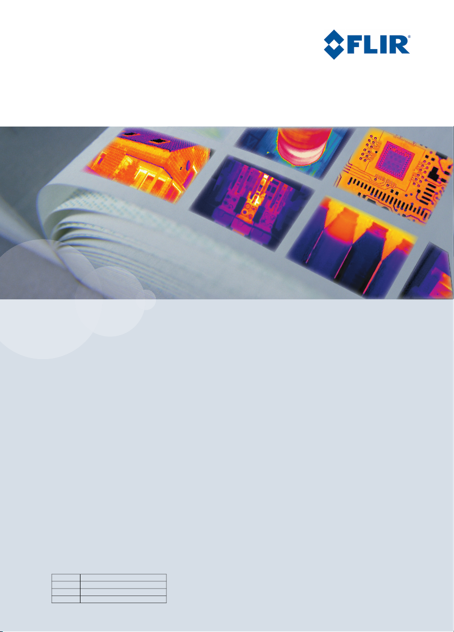
8 Camera parts and indicators
8.1 Camera parts
Figure
Explanation
10782603;a2
This table explains the figure above:
Focus ring on the infrared lens.1
Digital camera lamp.2
Digital camera.3
Digital camera lamp.4
Lens cap.5
USB-A connector (to connecta USB memorystick, a Bluetooth®USB micro
6
adapter, or another USB device, to the camera).
microSD™ Memory Card slot.7
USB Mini-B connector (to connect the camera to a PC).8
10 Publ. No. T559059 Rev. a460 – ENGLISH (EN) – July 1, 2010
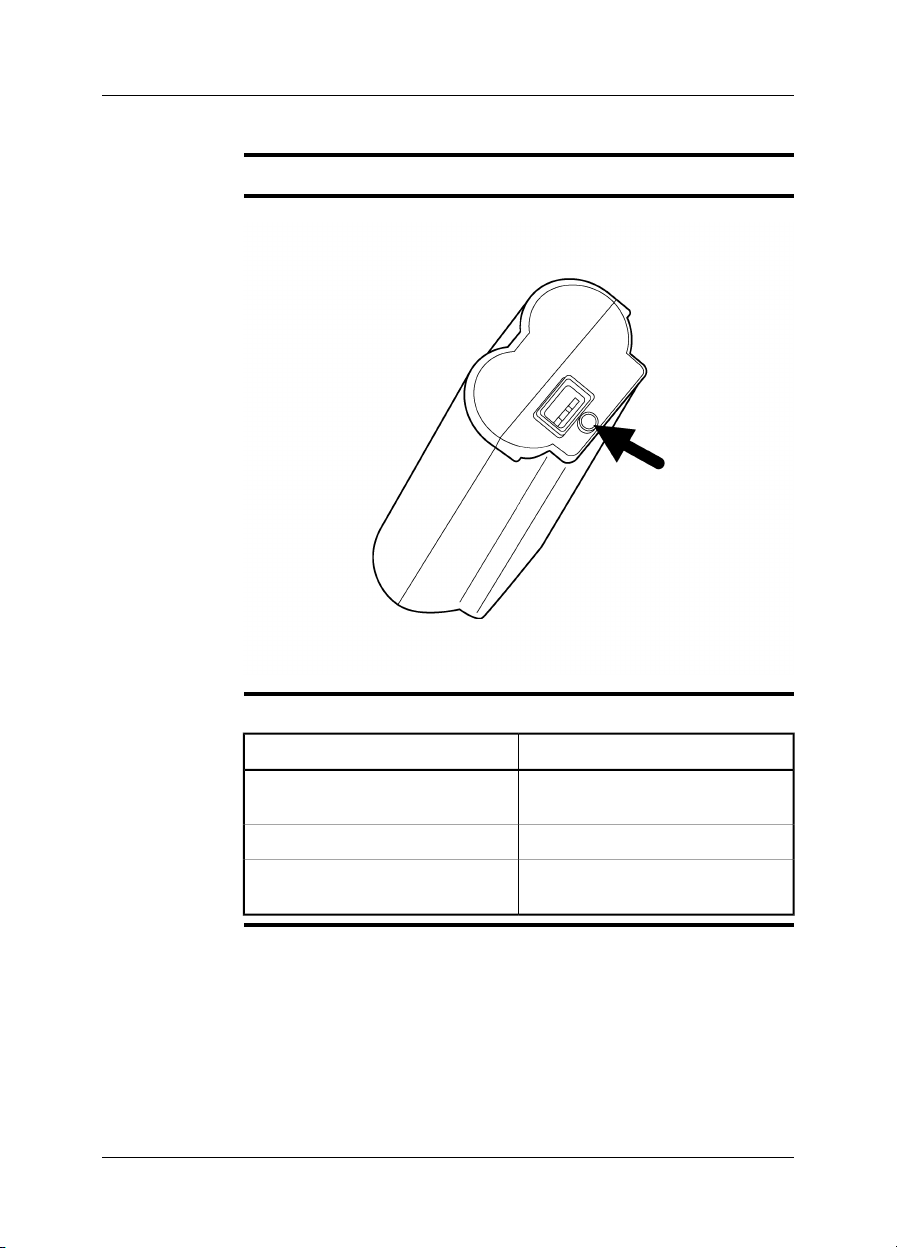
Page 23

8 – Camera parts and indicators
Laser pointer.9
Trigger to save images.10
Cover for the battery compartment, including release button.11
NOTE
The laser pointer may not be enabled in all camera models.
Publ. No. T559059 Rev. a460 – ENGLISH (EN) – July 1, 2010 11
Page 24
8 – Camera parts and indicators
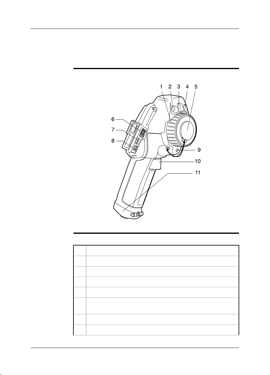
8.2 Keypad and LCD
Figure
Explanation
10782703;a2
This table explains the figure above:
Protective rubber frame for the LCD.1
LCD.2
Navigation pad.3
Left selection button. This button is context-sensitive.4
Camera/archive button. This button is used to switch between the camera
5
mode and the archive mode.
Button to activate the laser pointer.6
Power indicator.7
Right selection button. This button is context-sensitive.8
On/off button.9
NOTE
The laser pointer may not be enabled in all camera models.
12 Publ. No. T559059 Rev. a460 – ENGLISH (EN) – July 1, 2010
Page 25
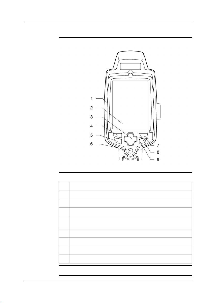
8.3 Power indicator
8 – Camera parts and indicators
General
Figure
Explanation
The camera has two power modes. An indicator shows these modes.
10782203;a2
This table explains the indicator:
ExplanationSignal type
The camera is on.The green light is continuous.
The camera is off.The green light is off.
NOTE
If the green light flashes ten times per second the camera has a hardware problem.
Contact your local salesoffice for instructionson where tosend the camerafor service.
Publ. No. T559059 Rev. a460 – ENGLISH (EN) – July 1, 2010 13
Page 26
8 – Camera parts and indicators
8.4 Battery condition indicator
General
Figure
Explanation
The battery has a battery condition indicator.
10715703;a3
This table explains the battery condition indicator:
ExplanationType of signal
The battery is being charged.The green light flashes two times per
second.
The battery is fully charged.The green light is continuous.
The green light is off.
The camerais usingthebattery (instead
of the power supply).
14 Publ. No. T559059 Rev. a460 – ENGLISH (EN) – July 1, 2010
Page 27
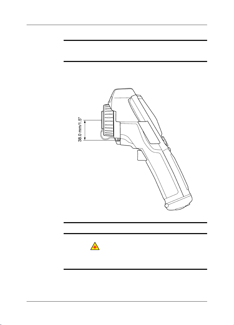
8.5 Laser pointer
8 – Camera parts and indicators
General
Figure
The camera has a laser pointer. When the laser pointer is on, you can see a laser
dot approximately 38 mm (1.5 in.) below the target. In some camera models, the
position of the laser dot is indicated on the screen.
This figure showsthe difference in position between the laser pointer and the optical
center of the infrared lens:
10781703;a1
WARNING
NOTE
Do not look directly into the laser beam: it can cause eye irritation.
The laser pointer may not be enabled in all camera models.
■
The symbol is displayed on the screen when the laser pointer is on.
■
The distance between the laser beam and the image center changes because of
■
the target distance. Look at the screen to make sure that it displays the correct
target.
Publ. No. T559059 Rev. a460 – ENGLISH (EN) – July 1, 2010 15
Page 28

8 – Camera parts and indicators
Laser warning
label
Laser rules and
regulations
A laser warning label with the following information is attached to the camera:
10743603;a2
Wavelength: 635 nm. Max. output power: 1 mW.
This product complies with 21 CFR 1040.10 and 1040.11 except for deviations pur-
suant to Laser Notice No. 50, dated June 24, 2007.
16 Publ. No. T559059 Rev. a460 – ENGLISH (EN) – July 1, 2010
Page 29
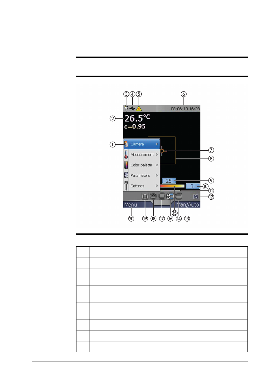
9 Screen elements
General
Figure
Explanation
You use screen elements – tools, menus, and selections in dialog boxes – to control
the camera program. This section describes the typical set of screen elements.
10782803;a1
This table explains the figure above:
Menu system.1
Measurement resultstable, including informationabout the emissivityvalue.2
Power indicator. When the camera is powered using a battery, a battery
3
level indicator is displayed.
USB indicator. This indicator is displayed when the camera is connected
4
to a computer using a USB cable.
Laser pointer indicator. This indicator is displayed when the laser pointer
5
is activated.
Date and time.6
Measurement spot.7
Measurement area.8
Publ. No. T559059 Rev. a460 – ENGLISH (EN) – July 1, 2010 17
Page 30

9 – Screen elements
Limit value for an isotherm in the temperature scale.9
Limit value for the temperature scale.10
Temperature span indicator.11
Indicator for automatic or manual mode (A/M).12
Current function for the right selection button.13
Tool to change the maximum temperature.14
Temperature scale.15
Tool to change the maximumand minimum temperaturesat the sametime.16
Tool to change the minimum temperature.17
Tool to set an isotherm.18
Tool to resize the Picture-in-Picture area.19
Current function for the left selection button.20
NOTE
Some of these screen elements are mutually exclusive.
18 Publ. No. T559059 Rev. a460 – ENGLISH (EN) – July 1, 2010
Page 31

10 Connectors and storage media
10.1 Power connector
General
Figure
SEE ALSO
You connect a power cable to the camera
to charge the battery
■
to use the power supply to operate the camera.
■
10601403;a2
For information on the pin configuration, see section 21 – Pin configurations on
page 68.
Publ. No. T559059 Rev. a460 – ENGLISH (EN) – July 1, 2010 19
Page 32

10 – Connectors and storage media
10.2 USB connectors
General
Supported
Extech®meters
Figure
You use the USB connectors in either of the following situations:
To move images from the camera memory to a computer. In this case, use the
■
small connector (USB Mini-B).
To connect an USB memory stick to the camera. In this case, use the large con-
■
nector (USB-A).
To connect a Bluetooth®USB micro adapter to the camera, in order to capture
■
measurement results from an external Extech®meter. In this case, use the large
connector (USB-A).
Extech®Moisture Meter MO297
■
Extech®Clamp Meter EX845
■
10782503;a2
Explanation
This table gives an explanation to the figure above:
One of the following:
1
Memory stick.
■
Bluetooth®USB micro adapter.
■
USB cable with an USB Mini-B connector (to connect the camera to a PC).2
20 Publ. No. T559059 Rev. a460 – ENGLISH (EN) – July 1, 2010
Page 33

10 – Connectors and storage media
10.3 Inserting and removing MicroSD™ Memory Cards
Figure
Procedure
10782303;a4
Follow this procedure to insert and remove a MicroSD™ Memory Card:
Open the rubber cover that protects the card slot.1
Push the MicroSD™ Memory Card firmly into the card slot, until a click is
2
heard.
To remove the MicroSD™ Memory Card, push the card again.3
Publ. No. T559059 Rev. a460 – ENGLISH (EN) – July 1, 2010 21
Page 34

11 Pairing Bluetooth®devices
General
Procedure
Before youcan usea Bluetooth®device withthe camera,youneed topair the devices.
Follow this procedure:
Insert a Bluetooth®USB micro adapter intothe large USBconnector (USB-
1
A).
Turn on the camera.2
To display the main menu, push Menu.3
To select Settings, push the navigation pad up/down.4
To enable the menu, push Select.5
To select Bluetooth, push the navigation pad up/down.6
To enable the menu, push Select.7
To select Add device, push the navigation pad up/down.8
To enable the menu, push Select.
9
At this stage youneed to referto the userdocumentation for yourBluetooth
device. During the pairing sequence you may need to refresh the dialog
box by clicking Refresh.
®
22 Publ. No. T559059 Rev. a460 – ENGLISH (EN) – July 1, 2010
Page 35

12 Fetching data from external
Extech®meters
General
Figure
Supported
Extech®meters
You can fetch data froman external Extech®meter andmerge this data intothe result
table in the infrared image.
T638370;a1
Extech®Moisture Meter MO297
■
Extech®Clamp Meter EX845
■
Technical support
for Extech®meters
NOTE
Procedure
Publ. No. T559059 Rev. a460 – ENGLISH (EN) – July 1, 2010 23
support@extech.com
This support contact is for Extech®meters only. For technical support for infrared
cameras, go to http://flir.custhelp.com.
This procedureassumes that you have pairedthe Bluetooth®devices. Forinstruc-
■
tions on how to do that, see section 11 – Pairing Bluetooth® devices on page 22
For more information about products from Extech Instruments, go to
■
http://www.extech.com/instruments/
Follow this procedure:
Turn on the camera.1
Turn on the Extech®meter.2
Page 36

12 – Fetching data from external Extech® meters
On the meter, enable Bluetooth®mode. Refer to the user documentation
3
for the meter for information on how to do this.
On the meter, choose the quantity that you want to use (voltage, current,
4
resistance, etc.). Refer to the user documentation forthe meter for information on how to do this.
Results from the meterwill now automaticallybe displayed inthe resulttable
in the top left corner of the infrared camera screen.
To save the image with the currently displayed result from the meter, pull
5
the trigger.
(Optional step)
6
To add an additional value from the meter, do the following
1 Recall the infrared image from the archive.
2 On the meter, choose the quantitythat you want to use (voltage, current,
resistance, etc.).
3 Using the meter, take a new measurement.
4 On the infrared camera, pull the trigger to add the new measurement
value to the image.
5 Confirm that you want to save the changed image.
24 Publ. No. T559059 Rev. a460 – ENGLISH (EN) – July 1, 2010
Page 37

12 – Fetching data from external Extech® meters
12.1 Typical moisture measurement and documentation procedure
General
Procedure
The following procedure can form the basis for other procedures using Extech
meters and infrared cameras.
Follow this procedure:
Use the infrared camera to identify any potential damp areas behind walls
1
and ceilings.
Use the moisture meter to measure the moisture levels at various suspect
2
locations that may have been found.
When a spot of particular interest is located, store the moisture reading in
3
the moisture meter’s memory and identify the measurement spot with a
handprint or other thermal identifying marker.
Recall the reading from the meter memory. The moisture meter will now
4
continuously transmit this reading to the infrared camera.
Use the camera to take a thermal image of the area with the identifying
5
marker. The stored data from the moisture meter will also be saved on the
image.
®
Publ. No. T559059 Rev. a460 – ENGLISH (EN) – July 1, 2010 25
Page 38

13 Choosing camera modes and
adjusting images
13.1 Choosing the camera mode
General
Procedure
You can use the camera in three different camera modes:
As an infrared camera. In this mode, the camera works as an ordinary infrared
■
camera and can display and save only infrared images.
As a digital camera. In this mode, the camera works as a digital camera, not that
■
dissimilar from a consumer digital camera.
Using the Picture-in-Picture feature. In this mode, a center portion of the digital
■
image is displayed in infrared.
You can change the camera mode at any time.
Follow this procedure to change the camera mode:
To display the main menu, push Menu.1
To select Camera, push the navigation pad up/down.2
To enable the menu, push Select.3
Select one of the following, using the navigation pad:
4
Infrared
■
Digital camera
■
Picture-in-Picture
■
Push Select.5
26 Publ. No. T559059 Rev. a460 – ENGLISH (EN) – July 1, 2010
Page 39

13 – Choosing camera modes and adjusting images
13.2 Adjusting the camera focus
Figure
10782103;a1
Procedure
Follow this procedure to adjust the camera focus:
Hold the camera tightly in your hand.1
Hold the focus ring with the other hand.2
Do one of the following:
3
Turn the focus ring counter-clockwise for far focus.
■
Turn the focus ring clockwise for near focus.
■
Publ. No. T559059 Rev. a460 – ENGLISH (EN) – July 1, 2010 27
Page 40

13 – Choosing camera modes and adjusting images
13.3 Auto-adjusting an image
General
Procedure
NOTE
For the best image brightness and contrast, auto-adjust the camera before you
measure a temperature and save an image.
If the letter M is displayed in the bottom right corner of the screen, push Man./Auto
once to auto-adjust the image.
If the letter A is displayed in the bottom right corner of the screen, the camera is already auto-adjusted for the best image brightness and contrast.
28 Publ. No. T559059 Rev. a460 – ENGLISH (EN) – July 1, 2010
Page 41

13 – Choosing camera modes and adjusting images
13.4 Adjusting an image manually
General
Figure
SEE ALSO
If you want to analyze an object with a wide range of temperatures, you can use the
colors of the scale on different parts of the object.
In the left image below, a correct analysis of the circled cable is difficult to make if
you only auto-adjust the image. You can analyze this cable in more detail if you increase or decrease
the maximum temperature level
■
the minimum temperature level
■
the maximum and minimum temperature levels at the same time.
■
This figure shows two infrared images of cable connection points.
The left image is auto-adjusted. In the right image, the maximum and minimum
temperature levels have been changed totemperature levels near the object of interest. In the temperature scale to the right of each image you can see how the temperature levels were changed.
10577503;a2
For procedures on how to adjust the image manually, see these sections:
Section 13.4.1 – Increasing or decreasing the maximum temperature level on
■
page 30
Section 13.4.2 – Increasing or decreasing the minimum temperature level on
■
page 31
Section 13.4.3 – Changing both the maximum and minimum temperature levels
■
at the same time on page 32
Publ. No. T559059 Rev. a460 – ENGLISH (EN) – July 1, 2010 29
Page 42

13 – Choosing camera modes and adjusting images
13.4.1 Increasing or decreasing the maximum temperature level
Procedure
Follow this procedure to increase or decrease the maximum temperature level:
Do one of the following:
1
If the letter A is displayed in the bottom right corner of the screen, push
■
Man./Auto once.
If the letter M is displayed in the bottom right corner of the screen, go
■
to Step 2 below.
2
To select , push the navigation pad left/right.
To change the value, push the navigation pad up/down.3
30 Publ. No. T559059 Rev. a460 – ENGLISH (EN) – July 1, 2010
Page 43

13 – Choosing camera modes and adjusting images
13.4.2 Increasing or decreasing the minimum temperature level
Procedure
Follow this procedure to increase or decrease the minimum temperature level:
Do one of the following:
1
If the letter A is displayed in the bottom right corner of the screen, push
■
Man./Auto once.
If the letter M is displayed in the bottom right corner of the screen, go
■
to Step 2 below.
2
To select , push the navigation pad left/right.
To change the value, push the navigation pad up/down.3
Publ. No. T559059 Rev. a460 – ENGLISH (EN) – July 1, 2010 31
Page 44

13 – Choosing camera modes and adjusting images
13.4.3 Changing both the maximum and minimum temperature levels at the same time
Procedure
Follow this procedure to change both the maximum and minimum temperature at
the same time:
Do one of the following:
1
If the letter A is displayed in the bottom right corner of the screen, push
■
Man./Auto once.
If the letter M is displayed in the bottom right corner of the screen, go
■
to Step 2 below.
2
To select , push the navigation pad left/right.
To change the value, push the navigation pad up/down.3
32 Publ. No. T559059 Rev. a460 – ENGLISH (EN) – July 1, 2010
Page 45

14 Working with measurements
14.1 Measuring a temperature using a spotmeter
General
Procedure
NOTE
You can measurethe temperature usinga fixed spotmeterin the middleof the screen.
Follow this procedure to measure the temperature using a fixed spotmeter:
To display the main menu, push Menu.1
To select Measurement, push the navigation pad up/down.2
To enable the menu, push Select.3
To select Temperature, push the navigation pad up/down.4
To save the changes and close the menu, push Select.5
Point the camera at the object you want to measure. The temperature is
6
displayed in the top left corner of the screen.
To display the temperature correctly, the circle in the middle of the spotmeter must
be completely filled by the object.
Publ. No. T559059 Rev. a460 – ENGLISH (EN) – July 1, 2010 33
Page 46

14 – Working with measurements
14.2 Measuring a temperature using an area
General
Procedure
You can measure the minimum or maximum temperature using a fixed area in the
middle of the screen.
Follow this procedure to measure the minimum or maximum temperature using a
fixed area:
To display the main menu, push Menu.1
To select Measurement, push the navigation pad up/down.2
To enable the menu, push Select.3
Do one of the following:
4
To create anarea for which the minimum temperature is indicated in the
■
top left corner of the screen, push the navigation pad up/down to select
Area min. and push Select.
To create an area for which the maximum temperature is indicated in
■
the top left corner of the screen, push the navigation pad up/down to
select Area max. and push Select.
Point the camera at the object you want to measure.5
34 Publ. No. T559059 Rev. a460 – ENGLISH (EN) – July 1, 2010
Page 47

15 Working with alarms
15.1 Setting a color alarm
General
Procedure
NOTE
A color alarm assigns a special color to all temperatures above or below a set temperature level.
Follow this procedure to set a color alarm:
To display the main menu, push Menu.1
To select Measurement, push the navigation pad up/down.2
To enable the menu, push Select.3
Do one of the following:
4
To set a color alarm below a set temperature level, push the navigation
■
pad up/down to select Below.
To set a color alarm above a set temperature level, push the navigation
■
pad up/down to select Above.
Push Select.5
Push the navigation pad up/down to change the temperature level.6
You can seta color alarm when thetemperature level lies outside thecurrent temperature range. This means that the image will be completely covered by the alarm
color, or that the alarm color is not visible.
If this happens by mistake, do one of the following:
Change the temperature level for the color alarm again.
■
Change the temperature scale range (see section 13.4 – Adjusting an image
■
manually on page 29).
Publ. No. T559059 Rev. a460 – ENGLISH (EN) – July 1, 2010 35
Page 48

15 – Working with alarms
15.2 Setting a dewpoint alarm
General
Procedure
SEE ALSO
The dewpoint can be regarded as the temperature at which the humidity in a certain
volume of air willcondense asliquid water. At this point, the relativehumidity is 100%.
When you have set a number of environmental parameters, the Dewpoint alarm can
detect these areas that have a risk of condensation and warn you that there may be
a deficiency in the building structure.
Follow this procedure to set a dewpoint alarm:
To display the main menu, push Menu.1
To select Measurement, push the navigation pad up/down.2
To enable the menu, push Select.3
Push the navigation pad up/down to select Dewpoint.4
To enable the menu, push Select.5
Use the navigation pad and the left and right selection buttons to set the
6
relative humidity and the atmospheric temperature.
When you change these parameters and push Select, the dewpoint is
changed accordingly.
To save your changes and close the menu, push Close.7
Point thecamera at the area ofinterest. A greencolor indicates critical areas.8
For information about the theory behind dewpoint alarms, see section 24.3.7 – Humidity & dew point on page 115.
36 Publ. No. T559059 Rev. a460 – ENGLISH (EN) – July 1, 2010
Page 49

15.3 Setting an insulation alarm
15 – Working with alarms
General
Procedure
The Insulation alarm can detect areas where there may be an insulation deficiency
in the building. It will trigger when the insulation level falls below a preset value of
the energy leakage through a wall.
Different building codes recommend different values for the insulation level, but typical values are 0.6–0.8 for new buildings. Refer to your national building code for
recommendations.
Follow this procedure to set an insulation alarm:
To display the main menu, push Menu.1
To select Measurement, push the navigation pad up/down.2
To enable the menu, push Select.3
Push the navigation pad up/down to select Insulation.4
To enable the menu, push Select.5
Use the navigation pad and the left and right selection buttons to set the
6
following parameters:
Outdoor temp.
■
Indoor temp.
■
Insul. level (%)
■
When you change these parameters and push Select, the insulation temperature (Insul. temp.) is changed automatically.
To save your changes and close the menu, push Close.7
Point thecamera at the area ofinterest. A greencolor indicates critical areas.8
SEE ALSO
For informationabout the theorybehind insulation alarms,see section 24.3.8– Excerpt
from Technical Note ‘Assessing thermal bridging and insulation continuity’ (UK example) on page 116.
Publ. No. T559059 Rev. a460 – ENGLISH (EN) – July 1, 2010 37
Page 50

16 Working with files
16.1 Saving an image
General
Formatting
memory cards
Naming
convention
You can save one image or more images to the MicroSD™ Memory Card.
For best performance, memory cards should be formatted to the FAT (FAT16) file
system. Using FAT32-formatted memory cards may result in inferior performance.
To format a memory card to FAT (FAT16), follow this procedure:
Insert the memory card into a card reader that is connected to your com-
1
puter.
In Windows®Explorer, select My Computer and right-click the memory
2
card.
Select Format.3
Under File system, select FAT.4
Click Start.5
The naming convention for images is IR_xxxx.jpg, where xxxx is a unique counter.
When you selectRestore default the camera resets the counter and assigns the first
highest free file name for the new file.
38 Publ. No. T559059 Rev. a460 – ENGLISH (EN) – July 1, 2010
Page 51

16 – Working with files
Figure
10782403;a1
Procedure
NOTE
Pull and release the trigger to save one image to the MicroSD™ Memory Card.
When you save an image to the camera memory, the measured value is also
■
saved.
You can save 1000+ images to the MicroSD™ Memory Card.
■
The image file format is compatible with FLIR Reporter 8.3 and later
■
Publ. No. T559059 Rev. a460 – ENGLISH (EN) – July 1, 2010 39
Page 52

16 – Working with files
16.2 Opening an image
General
Procedure
When you save an image, it is stored on the MicroSD™ Memory Card.
To display the image again, you can open the image from the MicroSD™ Memory
Card.
Follow this procedure to open an image:
To open the image archive, push the camera/archive button.1
Do one of the following:
2
To find the image you want to open, push the navigation pad left/right.
■
To display thumbnails of all images, push the navigation pad up, and
■
follow this procedure:
1 To select the image you want to open, push the navigation pad
up/down or left/right.
2 To open the image, push Open.
To go back to the live infrared image, push the camera/archive button.3
40 Publ. No. T559059 Rev. a460 – ENGLISH (EN) – July 1, 2010
Page 53

16.3 Deleting an image
16 – Working with files
General
Procedure
You can delete an image from the MicroSD™ Memory Card.
Follow this procedure to delete an image:
To open the image archive, push the camera/archive button.1
Do one of the following:
2
To delete the currently displayed image, push Options, then select
■
Delete and confirm that you want to delete the image.
To delete another image, go to Step 3 below.
■
To display thumbnails of all images, push the navigation pad up.3
To select the image you want to delete, push the navigation pad up/down
4
or left/right.
Push Options.5
Push Delete.6
Confirm by pushing Delete.7
Publ. No. T559059 Rev. a460 – ENGLISH (EN) – July 1, 2010 41
Page 54

16 – Working with files
16.4 Deleting all images
General
Procedure
You can delete all images from the MicroSD™ Memory Card.
Follow this procedure to delete all images:
To open the image archive, push the camera/archive button.1
To display thumbnails of all images, push the navigation pad up.2
Push Options.3
Push Delete all images.4
Confirm by pushing Delete all images.5
42 Publ. No. T559059 Rev. a460 – ENGLISH (EN) – July 1, 2010
Page 55

16.5 Adding a voice annotation to an image
16 – Working with files
General
NOTE
Procedure
A voice annotation is an audio recording that is saved in an infrared image.
The voice annotation is recorded using a Bluetooth®microphone headset. The
recording can be played back in the camera, and in image analysis and reporting
software from FLIR Systems.
The reason for using annotations is to make reporting and post-processing more
efficient by providing essential information about the image.
This procedureassumes that youhave paired theBluetooth®devices. Forinstructions
on how to do that, see section 11 – Pairing Bluetooth® devices on page 22
Follow this procedure:
To open the image archive, push the camera/archive button.1
Do one of the following:
2
To find the image to which you want to add a voice annotation, push
■
the navigation pad left/right.
To display thumbnails of all images, push the navigation pad up, and
■
follow this procedure:
1 To select the imageto which youwant to adda voice annotation,push
the navigation pad up/down or left/right.
2 To open the image, push Open.
Push Options.3
To select Voice annotation, push the navigation pad up/down, then push
4
Select.
To select Add device, push the navigation pad up/down, then push Select.5
Do the following:
6
To start a recording, push Record.
■
To stop a recording, push Stop.
■
To go back to the live infrared image, push Close and confirm that you
7
want to save the voice annotation.
Publ. No. T559059 Rev. a460 – ENGLISH (EN) – July 1, 2010 43
Page 56

16 – Working with files
16.6 Playing back a voice annotation
General
NOTE
Procedure
You can play back a voice annotation that you have added to an image.
The camera does nothave a loudspeaker. To play back a voice annotation,you must
use the headset.
Follow this procedure:
To open the image archive, push the camera/archive button.1
Do one of the following:
2
To find the image for which you want to play back the voice annotation,
■
push the navigation pad left/right.
To display thumbnails of all images, push the navigation pad up, and
■
follow this procedure:
1 To select the image for which you want toplay back the voice annota-
tion, push the navigation pad up/down or left/right.
2 To open the image, push Open.
Push Options.3
To select Voice annotation, push the navigation pad up/down, then push
4
Select.
To select Play, push the navigation pad up/down, then push Select.5
Do the following:
6
To start playing back the voice annotation, push Play.
■
To stop playing back the voice annotation, push Pause.
■
To go back to the live infrared image, push Close.7
44 Publ. No. T559059 Rev. a460 – ENGLISH (EN) – July 1, 2010
Page 57

16.7 Deleting a voice annotation
16 – Working with files
General
Procedure
You can delete a voice annotation that you have added to an image.
Follow this procedure:
To open the image archive, push the camera/archive button.1
Do one of the following:
2
To find the image for which you want to delete the voice annotation,
■
push the navigation pad left/right.
To display thumbnails of all images, push the navigation pad up, and
■
follow this procedure:
1 To select the image for which you want to deletethe voiceannotation,
push the navigation pad up/down or left/right.
2 To open the image, push Open.
Push Options.3
To select Voice annotation, push the navigation pad up/down, then push
4
Select.
To select Clear, push the navigation pad up/down, then push Select.5
Confirm that you want to delete the voice annotation.6
To go back to the live infrared image, push Close.7
Publ. No. T559059 Rev. a460 – ENGLISH (EN) – July 1, 2010 45
Page 58

16 – Working with files
16.8 Moving images to a PC
General
Overview of
methods
Equipment
Method 1
You can move one or more images from the camera to a computer.
You can use eitherof three methods to move images from thecamera to acomputer:
Method 1: Move images when the camera is operating as a USB disk. With this
■
method you do not need to install FLIR QuickReport on your computer.
Method 2: Move images when the camera is connected to a PC using FLIR
■
QuickReport. FLIRQuickReport contains featuresfor image handlingand creation
of PDF reports.
Method 3: Move imagesfrom thecamera to the PC using the MicroSD™ Memory
■
Card.
To move the images from the camera, you need this equipment:
A computer with an IBM-PC operating system
■
The FLIR QuickReport software installed on the computer (Method 2 only)
■
A USB cable
■
Follow this procedure to move images when the camera is operating as a USB disk:
To display the main menu, push Menu.1
To select Settings, push the navigation pad up/down.2
To enable the Settings menu, push Select.3
To select USB cable, push the navigation pad up/down.4
To select Standard, push the navigation pad up/down.5
Click OK.6
Connect thecamera and useWindows®Explorer todrag-and-drop images
7
from the camera to the computer.
When you select Standard, a help screen is displayed on the camera. Read the
NOTE
■
help text carefully.
If the USB mode is set to Standard, the camera power goes off if Auto power off
■
is enabled.
46 Publ. No. T559059 Rev. a460 – ENGLISH (EN) – July 1, 2010
Page 59

16 – Working with files
Method 2
NOTE
Follow this procedure to move images to a PC with FLIR QuickReport:
To display the main menu, push Menu.1
To select Settings, push the navigation pad up/down.2
To enable the Settings menu, push Select.3
To select USB cable, push the navigation pad up/down.4
To select Network disk, push the navigation pad up/down.5
Click OK.6
Connect thecamera to the computer followingthe FLIR QuickReportUser’s
7
manual.
See the FLIR QuickReport User’s manual for more instructions.8
When you select Network disk, a help screen is displayed on the camera. Read the
help text carefully.
Publ. No. T559059 Rev. a460 – ENGLISH (EN) – July 1, 2010 47
Page 60

16 – Working with files
16.9 Copying an image to an external USB drive
General
Procedure
You can copy an image from the MicroSD™ Memory Card to an external USB drive.
Follow this procedure:
To open the image archive, push the camera/archive button.1
To display thumbnails of all images, push the navigation pad up.2
Use the navigation pad to select the image that you want to copy.3
Push Options.4
Select Copy to USB.5
48 Publ. No. T559059 Rev. a460 – ENGLISH (EN) – July 1, 2010
Page 61

16 – Working with files
16.10 Copying all images to an external USB drive
General
Procedure
You can copy all images from the MicroSD™ MemoryCard to an external USB drive.
Follow this procedure:
To open the image archive, push the camera/archive button.1
Push Options.2
Select Copy all to USB.3
Publ. No. T559059 Rev. a460 – ENGLISH (EN) – July 1, 2010 49
Page 62

17 Changing camera settings
17.1 Changing the colors
General
Procedure
You can change the colors that the camera uses to display different temperatures.
A different set of colors can make it easier to analyze an image.
Follow this procedure to change the color:
To display the main menu, push Menu.1
To select Color palette, push the navigation pad up/down.2
To enable the menu, push Select.3
To select a different color, push the navigation pad up/down.4
To close the menu, push Select.5
50 Publ. No. T559059 Rev. a460 – ENGLISH (EN) – July 1, 2010
Page 63

17.2 Changing the emissivity
17 – Changing camera settings
General
Example values
Procedure
Emissivity isa property that specifies how much radiation anobject emits, compared
with the radiation of a theoretical reference object at the same temperature (called
a ‘blackbody’). The radiation from an object is the sum of what it emits and what it
reflects.
Except for shiny metals, a value of 0.96 is acceptable for most applications.
Asphalt 0.96
0.75Brick
0.97Concrete
0.98Leather
0.90Paint
0.95Rubber
0.80Rust
0.91Stucco
0.96Tape
0.96Water
0.85Wood
Follow this procedure to change the emissivity:
To display the main menu, push Menu.1
To select Parameters, push the navigation pad up/down.2
To enable the menu, push Select.3
To select Emissivity, push the navigation pad up/down.4
To enable the Emissivity menu, push Select.5
Publ. No. T559059 Rev. a460 – ENGLISH (EN) – July 1, 2010 51
Page 64

17 – Changing camera settings
6
Do one of the following:
Do the following:
■
1 Use the joystick to select Emissivity.
2 Push Select.
3 Use the joystick to change the value.
4 Push Select to confirm.
Do the following:
■
1 Use the joystick to select Material.
2 Push Select.
3 Use the joystick to select a material.
4 Push Select to confirm.
NOTE
If you set theemissivity to a value lowerthan 0.5, awarning isdisplayed on thescreen.
This is to remind you that the value is unusually low.
52 Publ. No. T559059 Rev. a460 – ENGLISH (EN) – July 1, 2010
Page 65

17 – Changing camera settings
17.3 Changing the reflected apparent temperature
General
Typical examples
Procedure
For very accurate measurements, you must set the reflected apparent temperature.
The reflected apparent temperature compensates for the radiation from the surroundings reflected by the object into the camera.
If the emissivity islow and the object temperaturediffers significantly fromthe reflected
apparent temperature, it is especially important to set the reflected apparent temperature correctly.
It is, for example, important to set thereflected apparenttemperature in the following
situations:
When you use the camera to inspect a hot item under a cold winter sky.
■
When you use the camera to inspect an item in a room where there are hot fur-
■
naces or electrical cabinets at the other end of the room.
Follow this procedure to change the reflected apparent temperature:
Do one of the following:
1
If you already know the reflected apparent temperature, go to Step 7
■
below.
If you do not know the reflected apparent temperature, go to Step 2
■
below.
Crumple up a large piece of aluminum foil.2
Uncrumple the aluminum foil and attach it to a piece of cardboard of the
3
same size.
Put the piece of cardboardin front ofthe object youwant to measure.Make
4
sure that the side with the aluminum foil points toward the camera.
Set the emissivity to 1.0 (See section 17.2 – Changing the emissivity on
5
page 51.).
Measure the apparent temperature of the aluminum foil and write it down.
6
You will need this value when you set Reflected temp. in Step 12 below.
To display the main menu, push Menu.7
To select Parameters, push the navigation pad up/down.8
To enable the menu, push Select.9
To select Reflected temp., push the navigation pad up/down.10
To enable the Reflected temp. box, push Select.11
To select a different value, push the navigation pad up/down.12
To close the menu, push Select.13
Publ. No. T559059 Rev. a460 – ENGLISH (EN) – July 1, 2010 53
Page 66

17 – Changing camera settings
SEE ALSO
For more information abouthow tomeasure reflectedapparent tempetature, see the
ISO standard DIS 18434-1 and the ASTM standard ASTM E1862-97.
54 Publ. No. T559059 Rev. a460 – ENGLISH (EN) – July 1, 2010
Page 67

17 – Changing camera settings
17.4 Changing the external optics correction
General
Procedure
For very accurate measurements, you must set the following:
External optics temperature, i.e., the temperature of any protective windows etc.
■
that are set up between the camera and the object of interest. If no protective
window or protective shield is used, this value is irrelevant.
External optics transmission, i.e., the optical transmission of any protective win-
■
dows, etc. that are set up between the camera and the object of interest.
Follow this procedure:
To display the main menu, push Menu.1
To select Parameters, push the navigation pad up/down.2
To enable the menu, push Select.3
To select External optics correction, push the navigation pad up/down.4
To enable the External optics correction menu, push Select.5
Do one of the following:
6
Do the following:
■
1 Use the joystick to select Ext. Opt. Temperature.
2 Push Select.
3 Use the joystick to change the value.
4 Push Select to confirm.
Do the following:
■
1 Use the joystick to select Ext. Opt. Transmission.
2 Push Select.
3 Use the joystick to change the value.
4 Push Select to confirm.
Publ. No. T559059 Rev. a460 – ENGLISH (EN) – July 1, 2010 55
Page 68

17 – Changing camera settings
17.5 Changing other camera settings
General
Applicability
Procedure
Camera settings affect images and how the camera operates.
The procedure below is applicable to these settings:
Digital camera lamp (to enable or disable the lamp used for the digital camera,
■
and in the Picture-in-Picture mode)
Regional (to change the language, units and time format)
■
Time/date (to set the time and date)
■
Auto power off (to set thetime period afterwhich the camerapower automatically
■
switches off)
Display intensity (to set the intensity of the display)
■
Temperature range (to change the object temperature range that the camera
■
uses)
USB cable (to set the USB mode)
■
Firmware (to upgrade the camera firmware with a new version that is on a Mi-
■
croSD™ Memory Card.
Restore default (to restore the factory default values)
■
Follow this procedure to change the camera settings above:
To display the main menu, push Menu.1
To select Settings, push the navigation pad up/down.2
To enable the Settings menu, push Select.3
To select the settingyou want tochange, push the navigation pad up/down.4
Use the navigation pad and the context-sensitive buttons to change the
5
setting.
NOTE
If the USB mode is set to Standard, the camera power goes off if Auto power off is
enabled and the camera is left connected to a PC and not used.
56 Publ. No. T559059 Rev. a460 – ENGLISH (EN) – July 1, 2010
Page 69

18 Power system
18.1 Installing the battery
NOTE
Procedure
Use a clean, drycloth to removeany water ormoisture on the battery beforeyou install
it.
Follow this procedure to install the battery:
To openthe battery compartmentcover, pushdown the lockingmechanism.
1
10600803;a1
Push the battery into the battery compartment.
2
10601603;a1
Push the battery compartment cover into position.
3
10601103;a1
Publ. No. T559059 Rev. a460 – ENGLISH (EN) – July 1, 2010 57
Page 70

18 – Power system
18.2 Removing the battery
Procedure
Follow this procedure to remove the battery:
To openthe battery compartmentcover, pushdown the lockingmechanism.
1
10600803;a1
Pull out the battery from the battery compartment.
2
10601003;a1
Push the battery compartment cover into position.
3
10601103;a1
58 Publ. No. T559059 Rev. a460 – ENGLISH (EN) – July 1, 2010
Page 71

18.3 Charging the battery
18 – Power system
NOTE
General
SEE ALSO
You must charge the battery for four hours before you use the camera for the first
time.
You must charge the battery when the message Battery voltage is low is displayed
on the screen.
Carry out one of the following procedures to charge the battery:
Use the combined power supply and battery charger to charge the battery when
■
it is inside the camera.
Use the combined power supply and battery charger to charge the battery when
■
it is outside the camera.
Use the two-bay battery charger to charge the battery. (The two-bay battery
■
charger is an item that is not included in the standard package.)
For information on how to charge the battery, see the following sections:
Section 18.3.1 – Usingthe combined powersupply and battery charger tocharge
■
the battery when it is inside the camera on page 60
Section 18.3.2 – Usingthe combined powersupply and battery charger tocharge
■
the battery when it is outside the camera on page 61
Section 18.3.3 – Using the two-bay battery charger to charge the battery on
■
page 62
Publ. No. T559059 Rev. a460 – ENGLISH (EN) – July 1, 2010 59
Page 72

18 – Power system
18.3.1 Using the combined power supply and battery charger to charge the battery when it is inside the camera
NOTE
Procedure
NOTE
SEE ALSO
For brevity, the ‘combined power supplyand battery charger’is called ‘power supply’
below.
Follow this procedure to use the power supply to charge the batterywhen it is inside
the camera:
To openthe battery compartmentcover, pushdown the lockingmechanism.1
Push the battery into the battery compartment.2
Push the battery compartment cover into position.3
On the battery compartment cover, open the rubber cover to access the
4
connector on the battery.
Connect the power supply cable plug to the connector on the battery.5
Connect the power supply mains-electricity plug to a mains socket.6
Disconnect thepower supply cable plug whenthe green lightof the battery
7
condition indicator is continuous.
The battery has a batterycondition indicator. When the green light is continuous, the
battery is fully charged.
For information about the battery condition indicator, see section 8.4 – Battery
■
condition indicator on page 14.
For information about how to install and remove the battery, see section 18.1 –
■
Installing the battery on page 57 and section 18.2 – Removing the battery on
page 58.
60 Publ. No. T559059 Rev. a460 – ENGLISH (EN) – July 1, 2010
Page 73

18 – Power system
18.3.2 Using the combined power supply and battery charger to charge the battery when it is outside the camera
NOTE
Procedure
NOTE
SEE ALSO
For brevity, the ‘combined power supplyand battery charger’is called ‘power supply’
below.
Follow thisprocedure to usethe powersupply to chargethe battery when it isoutside
the camera:
Put the battery on a flat surface.1
Connect the power supply cable plug to the connector on the battery.2
Connect the power supply mains-electricity plug to a mains socket.3
Disconnect thepower supply cable plug whenthe green lightof the battery
4
condition indicator is continuous.
The battery has a batterycondition indicator. When the green light is continuous, the
battery is fully charged.
For information about the battery condition indicator, see section 8.4 – Battery condition indicator on page 14.
Publ. No. T559059 Rev. a460 – ENGLISH (EN) – July 1, 2010 61
Page 74

18 – Power system
18.3.3 Using the two-bay battery charger to charge the battery
General
Procedure
NOTE
SEE ALSO
The two-bay battery charger gives you the option to charge two batteries at once.
Follow this procedure to use the two-bay battery charger to charge the battery:
Put the battery in the two-bay battery charger.1
Connect the power supply cable plug to the connector on the two-bay
2
battery charger.
Connect the power supply mains-electricity plug to a mains socket.3
Disconnect thepower supply cable plug whenthe green lightof the battery
4
condition indicator is continuous.
The two-bay battery charger is not included in the standard package.
■
The battery has a battery condition indicator. When the green light is continuous,
■
the battery is fully charged.
For information about the battery condition indicator, see section 8.4 – Battery
■
condition indicator on page 14.
For images and dimensions of the 2-bay battery charger, see section 22.3 – Two-
■
bay battery charger on page 74 and section 22.4 – Two-bay battery charger with
battery on page 75.
62 Publ. No. T559059 Rev. a460 – ENGLISH (EN) – July 1, 2010
Page 75

18.4 Turning on the camera
18 – Power system
Procedure
Push the on/off button to turn on the camera.
Publ. No. T559059 Rev. a460 – ENGLISH (EN) – July 1, 2010 63
Page 76

18 – Power system
18.5 Turning off the camera
Procedure
NOTE
Push and hold the on/off button for more than 0.5 seconds to turn off the camera.
If you do not use the camera, the power switches off after a time period that you can
set in the menu system. (See section 17.5 – Changing other camera settings on
page 56.).
64 Publ. No. T559059 Rev. a460 – ENGLISH (EN) – July 1, 2010
Page 77

19 Cleaning the camera
19.1 Camera housing, cables, and other items
Liquids
Equipment
Procedure
CAUTION
Use one of these liquids:
Warm water
■
A weak detergent solution
■
A soft cloth
Follow this procedure:
Soak the cloth in the liquid.1
Twist the cloth to remove excess liquid.2
Clean the part with the cloth.3
Do not apply solvents or similar liquids to the camera, the cables, or other items.
This can cause damage.
Publ. No. T559059 Rev. a460 – ENGLISH (EN) – July 1, 2010 65
Page 78

19 – Cleaning the camera
19.2 Infrared lens
Liquids
Equipment
Procedure
WARNING
CAUTION
Use one of these liquids:
96% isopropyl alcohol.
■
A commercial lens cleaning liquid with more than 30% isopropyl alcohol.
■
Cotton wool
Follow this procedure:
Soak the cotton wool in the liquid.1
Twist the cotton wool to remove excess liquid.2
Clean the lens one time only and discard the cotton wool.3
Make sure that you read all applicable MSDS (Material Safety Data Sheets) and
warning labels on containers before you use a liquid: the liquids can be dangerous.
Be careful when you cleanthe infraredlens. The lens has a delicate anti-reflective
■
coating.
Do not clean the infrared lens too vigorously. This can damage the anti-reflective
■
coating.
66 Publ. No. T559059 Rev. a460 – ENGLISH (EN) – July 1, 2010
Page 79

20 Technical data
For technical data, refer to the datasheets on the user documentation CD-ROM that
comes with the camera.
Publ. No. T559059 Rev. a460 – ENGLISH (EN) – July 1, 2010 67
Page 80

21 Pin configurations
Power connector
10601903;a1
Signal namePin
+12 V1
GND2
GND3
68 Publ. No. T559059 Rev. a460 – ENGLISH (EN) – July 1, 2010
Page 81

22 Dimensions
22.1 Camera
Figure
10781603;a1
Publ. No. T559059 Rev. a460 – ENGLISH (EN) – July 1, 2010 69
Page 82

22 – Dimensions
Figure
10781803;a2
70 Publ. No. T559059 Rev. a460 – ENGLISH (EN) – July 1, 2010
Page 83

22 – Dimensions
Figure
10781903;a1
Publ. No. T559059 Rev. a460 – ENGLISH (EN) – July 1, 2010 71
Page 84

22 – Dimensions
Figure
10782003;a2
72 Publ. No. T559059 Rev. a460 – ENGLISH (EN) – July 1, 2010
Page 85

22.2 Battery
22 – Dimensions
Figure
NOTE
10602103;a2
Use a clean, drycloth to removeany water ormoisture on the battery beforeyou install
it.
Publ. No. T559059 Rev. a460 – ENGLISH (EN) – July 1, 2010 73
Page 86

22 – Dimensions
22.3 Two-bay battery charger
Figure
10602203;a3
Use a clean, dry cloth to remove any water or moisture on the battery before you
NOTE
■
put it in the battery charger.
The two-bay battery charger is not included in the standard package.
■
74 Publ. No. T559059 Rev. a460 – ENGLISH (EN) – July 1, 2010
Page 87

22.4 Two-bay battery charger with battery
22 – Dimensions
Figure
NOTE
10602303;a3
Use a clean, dry cloth to remove any water or moisture on the battery before you
■
put it in the battery charger.
The two-bay battery charger is not included in the standard package.
■
Publ. No. T559059 Rev. a460 – ENGLISH (EN) – July 1, 2010 75
Page 88

23 Application examples
23.1 Moisture & water damage
General
NOTE
Figure
It is often possible to detect moisture and water damage in a house by using an infrared camera. This ispartly becausethe damaged area has adifferent heat conduction property and partly because it has a differentthermal capacity to storeheat than
the surrounding material.
Many factors can come into play as to how moisture or water damage will appear in
an infrared image.
For example,heating and coolingof these parts takes placeat different ratesdepending on the material and the time of day. For this reason, it is important that other
methods are used as well to check for moisture or water damage.
The imagebelow shows extensive waterdamage on anexternalwall where thewater
has penetrated the outer facing because of an incorrectly installed window ledge.
10739503;a1
76 Publ. No. T559059 Rev. a460 – ENGLISH (EN) – July 1, 2010
Page 89

23.2 Faulty contact in socket
23 – Application examples
General
NOTE
Figure
Depending on the type of connection a socket has, an improperly connected wire
can result in local temperature increase. This temperature increase is caused by the
reduced contact area between the connection point of the incoming wire and the
socket , and can result in an electrical fire.
A socket’s construction may differ dramatically from one manufacturer to another.
For this reason, different faults in a socket can lead to the same typical appearance
in an infrared image.
Local temperature increase can also result from improper contact between wire and
socket, or from difference in load.
The image below shows aconnection ofa cable to a socket where improper contact
in the connection has resulted in local temperature increase.
10739603;a1
Publ. No. T559059 Rev. a460 – ENGLISH (EN) – July 1, 2010 77
Page 90

23 – Application examples
23.3 Oxidized socket
General
NOTE
Figure
Depending on the typeof socket andthe environment in which thesocket is installed,
oxides may occur on the socket's contact surfaces. These oxides can lead to locally
increased resistance when the socket is loaded, which can be seen in an infrared
image as local temperature increase.
A socket’s construction may differ dramatically from one manufacturer to another.
For this reason, different faults in a socket can lead to the same typical appearance
in an infrared image.
Local temperature increase can also result from improper contact between a wire
and socket, or from difference in load.
The image below shows a series of fuses where one fuse has a raised temperature
on the contact surfaces against the fuse holder. Because of the fuse holder’s blank
metal, the temperature increase is not visible there, while it is visible on the fuse’s
ceramic material.
10739703;a1
78 Publ. No. T559059 Rev. a460 – ENGLISH (EN) – July 1, 2010
Page 91

23.4 Insulation deficiencies
23 – Application examples
General
NOTE
Figure
Insulation deficiencies may result from insulation losing volume over the course of
time and thereby not entirely filling the cavity in a frame wall.
An infraredcamera allowsyou to seethese insulation deficienciesbecause they either
have a different heat conduction property than sections with correctly installed insulation, and/or show the area where air is penetrating the frame of the building.
When you are inspecting a building, the temperature difference between the inside
and outside should be at least 10°C (18°F). Studs, water pipes, concrete columns,
and similar components may resemble an insulation deficiency in an infrared image.
Minor differences may also occur naturally.
In the image below, insulation in the roof framing is lacking.. Due to the absence of
insulation, air has forcedits way into the roof structure, whichthus takes on a different
characteristic appearance in the infrared image.
10739803;a1
Publ. No. T559059 Rev. a460 – ENGLISH (EN) – July 1, 2010 79
Page 92

23 – Application examples
23.5 Draft
General
NOTE
Figure
Draft can be found under baseboards, around door and window casings, and above
ceiling trim. This type of draft is often possible to see with an infrared camera, as a
cooler airstream cools down the surrounding surface.
When youare investigating draftin a house,there should besub-atmosphericpressure
in the house. Close all doors, windows, and ventilation ducts, and allow the kitchen
fan to run for a while before you take the infrared images.
An infrared image of draft often shows a typical stream pattern. You can see this
stream pattern clearly in the picture below.
Also keep in mind that drafts can be concealed by heat from floor heating circuits.
The image below shows a ceiling hatch where faulty installation has resulted in a
strong draft.
10739903;a1
80 Publ. No. T559059 Rev. a460 – ENGLISH (EN) – July 1, 2010
Page 93

24 Introduction to building
thermography
24.1 Important note
All camera functions and features that are described in this section may not be supported by your particular camera configuration.
24.2 Typical field investigations
24.2.1 Guidelines
As will be noted in subsequent sections there are a number of general guidelines the
user should take heed of when carrying out building thermography inspection. This
section gives a summary of these guidelines.
24.2.1.1 General guidelines
■ The emissivity of the majority of building materials fall between 0.85 and 0.95.
Setting the emissivity value in the camera to 0.90 can be regarded as a good
starting point.
■ An infrared inspection alone should never be used as a decision point for further
actions. Always verify suspicions and findings using other methods, such as construction drawings, moisture meters, humidity & temperature datalogging, tracer
gas testing etc.
■ Change level and spanto thermally tune the infrared image and reveal more details.
The figurebelow shows the difference between a thermally untuned and a thermally
tuned infrared image.
10552103;a2
Figure 24.1 LEFT: A thermally untuned infrared image; RIGHT: A thermally tuned infrared image, after
having changed level and span.
Publ. No. T559059 Rev. a460 – ENGLISH (EN) – July 1, 2010 81
Page 94

24 – Introduction to building thermography
24.2.1.2 Guidelines for moisture detection, mold detection & detection of water damages
■ Building defects related to moisture and water damages may only show up when
heat has been applied to the surface, e.g. from the sun.
■ The presence of water changes the thermal conductivity and the thermal mass of
the building material. It may also change the surfacetemperature of building material due to evaporative cooling. Thermal conductivity is a material’s abilityto conduct
heat, while thermal mass is its ability to store heat.
■ Infrared inspection does not directly detect the presence of mold, rather it may be
used to find moisture where mold may develop or has already developed. Mold
requires temperatures between +4°C to +38°C (+40°F to +100°F), nutrients and
moisture to grow. Humidity levels above 50% can provide sufficient moisture to
enable mold to grow.
10556003;a1
Figure 24.2 Microscopic view of mold spore
24.2.1.3 Guidelines for detection of air infiltration & insulation deficiencies
■ For very accurate camera measurements, take measurements of the temperature
and enter this value in the camera.
■ It is recommended that there is a difference in pressure between the outside and
the inside of the building structure. This facilitates theanalysis of the infrared images
and reveals deficiencies that would not be visible otherwise. Although a negative
pressure of between 10 and 50 Pa is recommended, carrying out the inspection
at a lower negative pressure may be acceptable. To do this, close all windows,
doors and ventilation ducts and then run the kitchen exhaust fan for some time to
reach a negative pressure of 5–10 Pa (applies to residential houses only).
82 Publ. No. T559059 Rev. a460 – ENGLISH (EN) – July 1, 2010
Page 95

24 – Introduction to building thermography
■ A difference in temperaturebetween theinside andthe outsideof 10–15°C (18–27°F)
is recommended.Inspections can be carried out at a lower temperature difference,
but will make the analysis of the infrared images somewhat more difficult.
■ Avoid direct sunlight on a part of a building structure—e.g. a façade—that is to be
inspected from the inside. The sunlight will heat the façade which will equalize the
temperature differenceson theinside and mask deficiencies in the building structure.
Spring seasons with low nighttime temperatures (±0°C (+32°F)) and high daytime
temperatures (+14°C (+57°F)) are especially risky.
24.2.2 About moisture detection
Moisture in a building structure can originate from several different sources, e.g.:
■ External leaks, such as floods, leaking fire hydrants etc.
■ Internal leaks, such as freshwater piping, waste water piping etc.
■ Condensation, which is humidity in the air falling out as liquid water due to conden-
sation on cold surfaces.
■ Building moisture, which is any moisture in the building material prior to erecting
the building structure.
■ Water remaining from firefighting.
As a non-destructive detection method, using an infrared camera has a number of
advantages over other methods, and a few disadvantages:
DisadvantageAdvantage
The method is quick.
■
The methodis a non-intrusivemeansof investi-
■
gation.
The method does not require relocation of the
■
occupants.
The method features an illustrative visual pre-
■
sentation of findings.
The method confirms failure points and mois-
■
ture migration paths.
The method only detects surface temperature
■
differentials and can not see through walls.
The methodcan not detectsubsurfacedamage,
■
i.e. mold or structural damage.
24.2.3 Moisture detection (1): Low-slope commercial roofs
24.2.3.1 General information
Low-slope commercial roofing is one of the most common roof types for industrial
building, such as warehouses, industrial plants, machinery shops etc. Its major advantages over a pitched roof is the lower cost in material and building. However, due
to its design where snow and ice will not fall off by itself—as is the case for the majority of pitched roofs—it must be strongly built to support the accumulated weight of
both roof structure and any snow, ice and rain.
Publ. No. T559059 Rev. a460 – ENGLISH (EN) – July 1, 2010 83
Page 96

24 – Introduction to building thermography
Although a basic understanding of the construction of low-slope commercial roofs is
desirable whencarrying outa roof thermography inspection, expert knowledge is not
necessary. There is a large number of different design principles for low-slope commercial roofs—bothwhen itcomes tomaterial anddesign—and itwould beimpossible
for the infrared inspection person to know them all. If additional information about a
certain roof is needed, the architect or contractor of the building can usually supply
the relevant information.
Common causesof rooffailure areoutlined in the table below (from SPIE Thermosense
Proceedings Vol. 371 (1982), p. 177).
%Cause
47.6Poor workmanship
2.6Roof traffic
16.7Poor design
7.8Trapped moisture
8.0Materials
8.4Age & weathering
Potential leak locations include the following:
■ Flashing
■ Drains
■ Penetrations
■ Seams
■ Blisters
24.2.3.2 Safety precautions
■ Recommend a minimum of two people on a roof, preferably three or more.
■ Inspect the underside of the roof for structural integrity prior to walking on it.
■ Avoid stepping on blisters that are common on built up bitumen and gravel roofs.
■ Have a cell phone or radio available in case of emergency.
■ Inform local police and plant security prior to doing nighttime roof survey.
84 Publ. No. T559059 Rev. a460 – ENGLISH (EN) – July 1, 2010
Page 97

24 – Introduction to building thermography
24.2.3.3 Commented building structures
This section includes a few typical examples of moisture problems on low-slope
commercial roofs.
CommentStructural drawing
10553603;a2
Inadequate sealing of roof membrane around
conduit and ventilation ducts leading to local
leakage around the conduit or duct.
10553703;a2
Roof membrane inadequately sealed around roof
access hatch.
Publ. No. T559059 Rev. a460 – ENGLISH (EN) – July 1, 2010 85
Page 98

24 – Introduction to building thermography
10553803;a2
CommentStructural drawing
Drainage channels located too high and with too
low an inclination. Some water will remain in the
drainage channelafter rain, whichmay lead tolocal
leakage around the channel.
10553903;a2
Inadequate sealing between roof membrane and
roof outlet leading tolocal leakage aroundthe roof
outlet.
24.2.3.4 Commented infrared images
How do you find wet insulation below the surface of the roof? When the surface itself
is dry, including any gravel or ballast, a sunny day will warm the entire roof. Early in
the evening, if the sky is clear, the roof will begin to cool down by radiation. Because
of its higher thermal capacity the wet insulation will stay warmer longer than the dry
and will be visible in the infrared camera (see photos below). The technique is particularly effective on roofs having absorbent insulation—such as wood fiber, fiberglass,
and perlite—where thermal patterns correlate almost perfectly with moisture.
86 Publ. No. T559059 Rev. a460 – ENGLISH (EN) – July 1, 2010
Page 99

24 – Introduction to building thermography
Infrared inspections of roofs with nonabsorbent insulations, common in many singleply systems, are more difficult to diagnose because patterns are more diffuse.
This section includes a few typical infrared images of moisture problems on low-slope
commercial roofs:
CommentInfrared image
10554003;a1
Moisture detection on a roof, recorded during the
evening.
Since the building material affected by moisture
has ahigher thermal mass,itstemperature decreases slower than surrounding areas.
10554103;a1
10554203;a1
Water-damaged roofing components and insulation identified from infrared scan from the underside of the built-up roof on a structural concrete
tee deck.
Affected areas are cooler than the surrounding
sound areas, due to conductive and/or thermal
capacitive effect.
Daytime survey of built-up low-slope commercial
roof.
Affected areas are coolerthan the surroundingdry
areas, dueto conductiveand/orthermal capacitive
effect.
Publ. No. T559059 Rev. a460 – ENGLISH (EN) – July 1, 2010 87
Page 100

24 – Introduction to building thermography
24.2.4 Moisture detection (2): Commercial & residential façades
24.2.4.1 General information
Thermography has proven to be invaluable in the assessment of moisture infiltration
into commercial and residential façades. Being able to provide a physical illustration
of the moisture migration paths is more conclusive than extrapolating moisture meter
probe locations and more cost-effective than large intrusive test cuts.
24.2.4.2 Commented building structures
This section includes a few typical examples of moisture problems on commercial
and residential façades.
CommentStructural drawing
10554303;a2
Pelting rain penetrates the façade due to badly
executed bed joints. Moisture builds up in the
masonry above the window.
10554403;a2
Pelting rain hits the window at an angle. Most of
the rain runs off the window edge flashing but
some finds its way into the masonry where the
plaster meets the underside of the flashing.
88 Publ. No. T559059 Rev. a460 – ENGLISH (EN) – July 1, 2010
 Loading...