

Page 1
INSTALLATION MANUAL
Large Format Infrared Inspection Windows
Models IRW-xPC/xPS™
Page 2
IRW-xPC/xPS-en-GB_AA
INSTALLATION MANUAL - IRW-xPC/xPS - EN
Introduction
Thank you for selecting the FLIR IR window. This manual applies to models
IRW-6PC (6”), IRW-12PC (12”), and IRW-24PC (24”) aluminum windows and
IRW-6PS (6”), IRW-12PS (12”), and IRW-24PS (24”) stainless steel windows.
Preparation
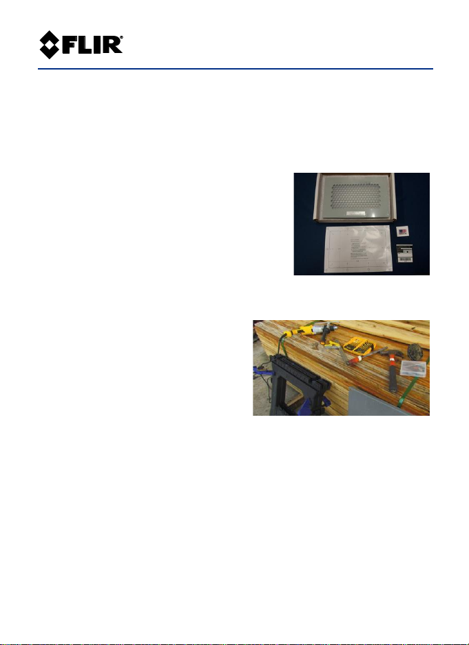
Check that the package contains the IR
window, fitting template, IR window label, and
fitting hardware. See Fig-1.
The required tools and personal protection
equipment (PPE) are listed below; you will
need these materials to perform a successful
installation. Install the window on a vertical, flat surface; cut the
installation holes using an angle grinder or a nibbler tool.
Required Tools
• Metal cutting tool such as nibbler or
angle grinder (see Fig-2)
• Drill and 8mm (5/16
”
) drill bit
• Center punch
• De-burring tool or another file tool
• Socket or wrench (7/16”)
• Metal treatment product with anti-corrosion properties (paint, sealer)
Personal Protection Equipment (PPE)
Work gloves and safety glasses are required. Please comply with all site PPE
requirements.
Transmission Rate
Determine the transmission rate of the IR window you are installing. Notate
the transmission rate on the supplied IR window label.
Fig-1
Fig-2
Page 3

IRW-xPC/xPS-en-GB_AA
Field of View
The Field of View table, below, shows the horizontal and vertical views (in
inches) for a variety of target distances for all models in this series. The
table is based on an IR camera with a standard 24o lens (2” lens diameter)
and 30o (max.) viewing angle (horizontal and vertical).
Field of View Reference Table (inches)
IR Target Distance
IRW-6PC_PS
IRW-12PC_PS
IRW-24PC_PS
8 inches
H = 18.0
V = 14.7
H = 35.1
V = 18.6
H = 70.8
V = 20.4
12 inches
H = 28.2
V = 18.3
H = 39.9
V = 22.2
H = 75.6
V = 24.0
18 inches
H = 35.2
V = 23.55
H = 46.9
V = 27.45
H = 82.6
V = 26.25
24 inches
H = 41.7
V = 28.8
H = 89.1
V = 32.7
H = 89.1
V = 34.5
Fitting the template
Affix the supplied cutting template to the
appropriate area of the panel (Fig-3).
Hole punching
With the center punch, mark all fixing holes
labelled ‘A’ on the cutting template (Fig-4).
Drilling holes
Drill the center-punched holes using an 8mm (5/16”)
drill bit. If using a nibbler, drill a pilot hole along the
line labelled ‘B’.
Cut-out sizing
Refer to the table below to determine the size of the cut-out.
Fig-3
Fig-4
Page 4

IRW-xPC/xPS-en-GB_AA
Cut-out Hole Sizing Reference Table
Model
Cut-out (mm)
Cut-out (in.)
Number of fixing holes
IRW-6PC_6PS
177 x 119
6.96 x 4.7
Eight (8)
IRW-12PC_12PS
262 x 164
10.3 x 6.44
Ten (10)
IRW-24PC_24PS
568 x 176
22.36 x 6.92
Fourteen (14)
Making the cut-out
Make the cut-out using a nibbler, grinder, or similar
tool. Fig-5 shows an angle grinder fitted with a metal
cutting disc. After cutting a hole, smooth the rough
edges with a de-burring tool or file, and peel away
the remaining portion of the cutting template. To
protect against long-term corrosion, treat bare
metal surfaces with an anti-corrosion coating (paint,
sealer, etc.).
Installing the IR window
After cutting the hole, install the window:
• Place the unit, complete with seals, on the front of the panel
• Fit the hardware, ensuring that a nut is affixed on each stud
• With the 7/16” wrench, tighten the hardware to these specifications: 40
inch/lbs. or 4.52Nm
Attaching the label
Correctly label the IR window. We supply each IR window with a label; this
allows the camera operator to note the number of targets, target
emissivity, and transmission rates of the viewing pane for a variety of IR
cameras.
There may be multiple targets viewed through the IR viewing window; the
label can reflect these. The most common method of locating the required
targets is using the clock-face method, i.e. breakers at 4 o’clock position,
etc. Place all such data on the label. This label also uses a pre-printed bar
code system to allow for unique identification of each IR window.
Fig-5
Page 5

IRW-xPC/xPS-en-GB_AA
Limited Lifetime Warranty
This product is protected by the FLIR Limited Lifetime Warranty. Visit
www.flir.com/testwarranty to read the full warranty and to register your product.
Specifications
Part No.
IRW-6PC
IRW-12PC
IRW-24PC
IRW-6PS
IRW-12PS
IRW-24PS
Overall Height*
21.8cm
20.6cm
21.8cm
21.8cm
20.6cm
21.8cm
8.6 in.
8.1 in.
8.6 in.
8.6 in.
8.1 in.
8.6 in.
Overall Width*
16cm
30.5cm
61cm
16cm
30.5cm
61cm
6.3 in.
12.0 in.
24.0 in.
6.3 in.
12.0 in.
24.0 in.
Optic Specifications
Overall
aperture Ht.
15.0cm
12.7cm
15.0cm
21.8cm
20.6cm
21.8cm
5.9 in.
5.0 in.
5.9 in.
5.9 in.
5.0 in.
5.9 in.
Overall
aperture Width
9.1cm
23.6cm
53.0cm
9.1cm
23.6cm
53.0cm
3.6 in.
9.3 in.
20.9 in.
3.6 in.
9.3 in.
20.9 in.
Temp. range
-40~325oC (-40~617oF) for optics
Materials and Ratings
IP/NEMA
IP65 / NEMA 4x
IP67 / NEMA 6
Operating
temperature
-40~200oC (-40~392oF) max.
-40~273oC (-40~523oF) max.
Body material
Aluminum
Powder Coated Stainless Steel
Grill material
Aluminum IP22 / IP2x Standard
Stainless Steel IP22 / IP2x Standard
Optic material
UL 746, visual, UV/IR transmissive polymer -40~325oC (-40~617oF)
Gasket
UL 94 TVA TPE -40~273oC (-40~523oF)
Hardware
316 Stainless Steel
Auto ground
Yes
Voltage range
Any
Agency
Approvals
Certified by UL (USA) & cUL (Canada) to the following standards: 50V, 50E, 756C: Impact
and Flammability, 1558: Impact and Load Resistance, 508A: ANSI 508A CSA C22.2 No.
14-13 IP65 / NEMA 4x Lloyds of London Type Approval American Bureau of Shipping
(ABS) DNV (Det Norske Veritas) P261.1E Maritime, Vessel and Offshore Applications
IEEE C37 20.2.a.3.6: Impact and Load BSI Quality ISO 9001 Certified
*These dimensions are not installation dimensions. Do not cut prior to receiving FLIR window and
installation template. For additional specifications, visit www.flir.com.
Page 6

IRW-xPC/xPS-en-GB_AA
Corporate Headquarters
FLIR Systems, Inc.
2770 SW Parkway Avenue
Wilsonville, OR 97070 USA
Customer Support
Repair, Calibration and Technical Support https://support.flir.com
Publication Identification No.: IRW-xPC_xPS
Release version: AA
Release Date: January 2019
Language: en-GB
Copyright © 2019 FLIR Systems, Inc.
All rights reserved including the right of reproduction in whole or in part in any form.
www.flir.com
 Loading...