

Page 1

Operating Instructions Guide
intelliRock® III
Page 2

Advisories
Copyright
© 2018, FLIR Systems, Inc. All rights reserved worldwide. No parts of the software including source code may
be reproduced, transmitted, transcribed or translated into any language or computer language in any form or
by any means, electronic, magnetic, optical, manual or otherwise, without the prior written permission of FLIR
Systems.
The documentation must not, in whole or part, be copied, photocopied, reproduced, translated or transmitted to
any electronic medium or machine-readable form without prior consent, in writing, from FLIR Systems. Names
and marks appearing on the products herein are either registered trademarks or trademarks of FLIR Systems
and/or its subsidiaries. All other trademarks, trade names or company names referenced herein are used for
identification only and are the property of their respective owners.
Quality Assurance
FLIR Systems is committed to a policy of continuous development; therefore, we reserve the right to make
changes and improvements on any of the products without prior notice.
Documentation
To access the latest manuals and notifications, go to the Download tab at: https://support.flir.com. It only takes
a few minutes to register online. In the download area you will also find the latest releases of manuals for our
other products, as well as manuals for our historical and obsolete products.
Disposal of Electronic Waste
As with most electronic products, this equipment must be disposed of in an environmentally friendly
way, and in accordance with existing regulations for electronic waste. Please contact your FLIR Systems representative for more details.
Publication Identication No.: iR3-en-1
Release Version: AA
Release Date: October 2018
Language: en-JR_MS
Page 3

intelliRock technical support: Visit www.flir.com/support or call (866) 276-8369, 9am - 5pm, EST
Table of Contents
Table of Contents 3
intelliRock® III Solution Overview 5
What’s new in intelliRock III 8
intelliRock Applications 8
Maturity 8
Temperature Profiling 9
intelliRock Reader Overview 9
IntelliRock Logger Overview 10
Decoding Logger Part Numbers 11
Logger Types 14
Reviewing Logger Data 12
Cloud Software Overview 12
Wireless Remote Overview 12
intelliRock III Quick Reference 14
intelliRock Reader Setup 14
Starting an intelliRock Logger 14
Reviewing Logger Data 14
Downloading Logger Data to the Reader 15
Transferring Data from a Reader to the intelliRock
Cloud 15
Using the Thermal Camera 15
Using the intelliRock III Reader 16
intelliRock III Reader Setup 16
Setting the Time and Date 17
Choosing Language Support 18
Establishing Bluetooth Connectivity 18
Reader Battery Life 19
Starting and Using Loggers 20
Starting an intelliRock Logger 20
Resetting a Logger 24
Reviewing Logger Data 24
Downloading Logger Data to the Reader 26
Entering Logger Data Notes 27
Viewing Graphs of Logger Data 28
Using the Thermal Camera 30
intelliRock III PC Software 33
Installing the intelliRock PC software 33
Connecting the intelliRock III Reader to the PC
34
Connecting via Micro USB 34
Connecting via Bluetooth 35
Click on bold section to jump to that page.
Transferring Logger Data to the PC 35
Transferring Calibrations to the Reader 36
Configuring 900 MHz Radio Connectivity for Remote Boxes 37
Using the intelliRock III Cloud Software 41
Logging in to The intelliRock Cloud 41
Administering and Managing Users 42
Creating or Managing Projects in the Cloud 43
Reviewing Project Data 45
Synchronizing Graph Data Based on Logger
Start Time 46
Setting Alerts 47
Viewing and Editing Alerts 48
Sharing Report Data 50
Calibrations 50
Viewing and Managing Existing Calibrations
51
Entering New Calibrations 52
Managing Cloud Settings and Remote Boxes
52
Viewing Thermal Images 54
Accessing the intelliRock Cloud from a Smartphone 55
Using the intelliRock Wireless Remote 57
Connecting Loggers to the Wireless Remote Box
58
Changing the Wireless Remote Box Name 58
Locating the Wireless Remote Box on the Site
59
Activating the Wireless Remote Box 60
Setting the Automatic Data Transfer Interval
60
Using 900 MHz Radio Connectivity for Remote
Boxes 60
Manually “Pushing” Data to the Cloud 61
Wireless Remote Box Battery Life 61
Placing Loggers in a Structure 62
Troubleshooting and Support 63
Warranty 64
Appendix 65
3
Page 4

intelliRock® III– Operating Instructions Guide
4
Page 5

intelliRock technical support: Visit www.flir.com/support or call (866) 276-8369, 9am - 5pm, EST
intelliRock® III Solution Overview
The intelliRock® III is the leading solution for concrete maturity and temperature profiling. The
system was first launched in 2000 and is now in its third generation of release. The intelliRock
III system is easier to use and has expanded capabilities compared to previous intelliRock generations. The system takes the guesswork out of concrete decision-making, allowing users to
report and review concrete data from anywhere using the intelliRock cloud software.
This guide provides operating instructions for the intelliRock III system, which consists of these
major components:
1. The intelliRock Reader: a handheld device for starting/stopping loggers, viewing numeric and graphical concrete data in the field, and transferring collected logger data to the
intelliRock PC software.
Figure 1.1: The intelliRock III Reader
5
Page 6

intelliRock® III– Operating Instructions Guide
2. Loggers: self-contained sensors that house a precision temperature measurement
system, microprocessor, memory, and a battery. Loggers are placed in concrete structures as they are poured and once a logger is started, it collects data about concrete
temperature or maturity for up to 180 days. There are two types of intelliRock III loggers:
temperature only, or maturity and temperature.
Figure 1.2: An intelliRock III Maturity Logger.
3. The intelliRock Cloud Software: a cloud-based repository of concrete temperature and
strength data, accessible from anywhere via mobile devices. The intelliRock Cloud allows users to securely store, display and share data from individual loggers, as well as
mix data and calibration curves. Using the cloud, users can generate graphic reports at
various levels of detail to aid concrete decision-making.
Figure 1.3: The intelliRock III Cloud Software home screen.
4. The intelliRock 8-Channel Wireless Remote: this optional accessory is a rugged, remote
connectivity device that supports connection of up to eight loggers. It transmits logger
data through either a 4G LTE cellular connection to the intelliRock cloud software, or via
a 900 MHz radio to a PC running the intelliRock PC software, where it is then uploaded
to the cloud. 900 MHz radio connectivity requires the optional base station.
6
Page 7

intelliRock technical support: Visit www.flir.com/support or call (866) 276-8369, 9am - 5pm, EST
Note: European users will have 3G wireless connectivity, with 4G planned in the future.
900 MHz connectivity is not available in the European market.
Figure 1.4: The intelliRock III Wireless Remote.
5. The intelliRock PC Uploader software: Microsoft Windows software used for transferring
logger data from the hand-held reader to a PC, and then from the PC to the intelliRock
Cloud Software. The PC software is also used to configure 900 MHz radio connectivity
to the intelliRock wireless remote device.
Figure 1.5: intelliRock PC Software home screen
7
Page 8

intelliRock® III– Operating Instructions Guide
What’s new in intelliRock III
Users that are familiar with previous generations of intelliRock will find many new features and
functions in intelliRock III:
• Logger standardization. The system uses two types of loggers. Maturity loggers that
support either the Nurse-Saul or Arrhenius methods, and temperature-only loggers.
Both types will log data at one-minute intervals for up to 180 days. Available logger cable
lengths are 4, 8, 15, 30, 50, or 100 feet.
• PSI data. When maturity loggers are in use and a mix’s calibration curve has been uploaded to the reader, the intelliRock III system will now display strength in either PSI or
MPa in addition to the temperature and maturity.
• Cloud software. The new intelliRock cloud software serves as the central repository for
concrete data collected from loggers for all jobs. Instead of transferring data from intelliRock readers through a PC and creating a .CSV file, the data now goes into the cloud
which provides enhanced reporting and visualization capabilities.
• Enhanced graphs. Graphs on the reader have improved view options, range selection
that allow you to view temperature and strength data overlayed. Slider controls in the
cloud software ensure that differentials are accurate when comparing data from multiple loggers, and max/min indicators.
• Full keyboard. The intelliRock III reader now features a full, alphabetic keyboard that
speeds up data entry.
• Reader display. The system now features a color screen with better resolution than the
intelliRock II system.
• Bluetooth support. A Bluetooth connection is now supported for transferring data between the reader and a PC.
• Remote cellular connectivity. The intelliRock wireless remote now supports automatic
transfer of logger data to the cloud via 4G LTE cellular connectivity in the U.S. or 3G in
some international locations. The wireless remote can optionally support 900 MHz radio
connectivity.
• PC Uploader Software. In addition to facilitating data transfer from the reader to the
PC, the Uploader now allows calibration curve data to be downloaded into the reader for
instant strength conversions.
• Micro-USB charging port. The reader now includes a micro-USB port that serves as the
PC interface and charges the battery.
• Thermal camera. A thermal camera is built-in to the intelliRock reader to enable capturing of thermal images of concrete structures to visually detect temperature differences.
intelliRock Applications
The intelliRock III system has two applications in concrete construction: estimation of in-place
concrete strength using the maturity method, or in-place concrete temperature profiling.
Maturity
The intelliRock III system estimates in-place concrete strength using the maturity method as
defined by the ASTM C1074 standard. The standard describes two methods for calculating
concrete maturity:
8
Page 9

intelliRock technical support: Visit www.flir.com/support or call (866) 276-8369, 9am - 5pm, EST
• The Nurse-Saul method which assumes that concrete strength development is a linear
function of hydration temperature.
• The Arrhenius method, which assumes that an exponential relationship exists between
compressive strength and hydration temperature.
The intelliRock III system supports both maturity methods. The project engineer should make
the decision about which method to use.
Temperature Profiling
Documenting the temperature profiles and gradients of in-place concrete is another application of the intelliRock III system. The thermal data captured by intelliRock temperature loggers
is uninterruptible and unalterable, providing proof of the thermal integrity of a placement. Concrete temperature profiling with intelliRock is ideal for cold-weather pours, mass pours, curing
tanks, and moist rooms.
intelliRock Reader Overview
Figure 1.6 identifies key aspects of the intelliRock III reader.
Figure 1.6: Key aspects of the intelliRock III reader.
9
Page 10

intelliRock® III– Operating Instructions Guide
The reader connects to a PC for logger data transfer and battery recharging using the microUSB port on the bottom of the reader, shown in Figure 1.7.
Figure 1.7: The micro-USB port location on the bottom of the intelliRock reader.
To connect a logger to the intelliRock III reader, use the terminals located on the top of the
reader, as shown in Figure 1.8.
Figure 1.8: The terminals for connecting a logger to the intelliRock reader.
Refer to the “Starting and Using Loggers” section of this guide for instructions on connecting,
starting and using intelliRock loggers.
IntelliRock Logger Overview
The intelliRock III system uses maturity and temperature loggers as shown in Figure 1.9.
Figure 1.9: An intelliRock III logger.
Available cable lengths for both types of loggers are 4, 8, 15, 30, 50, or 100 feet.
10
Page 11
intelliRock technical support: Visit www.flir.com/support or call (866) 276-8369, 9am - 5pm, EST
Under the direction of the project engineer, loggers are secured in place within a structure
before it is poured. They are arranged so that the resin-encased sensor is within the concrete
placement and the logger wires are exposed, outside of the placement where they are accessible for connecting to the intelliRock III reader or wireless remote. A subsequent section of this
guide provides best practices for securing loggers within a structure.
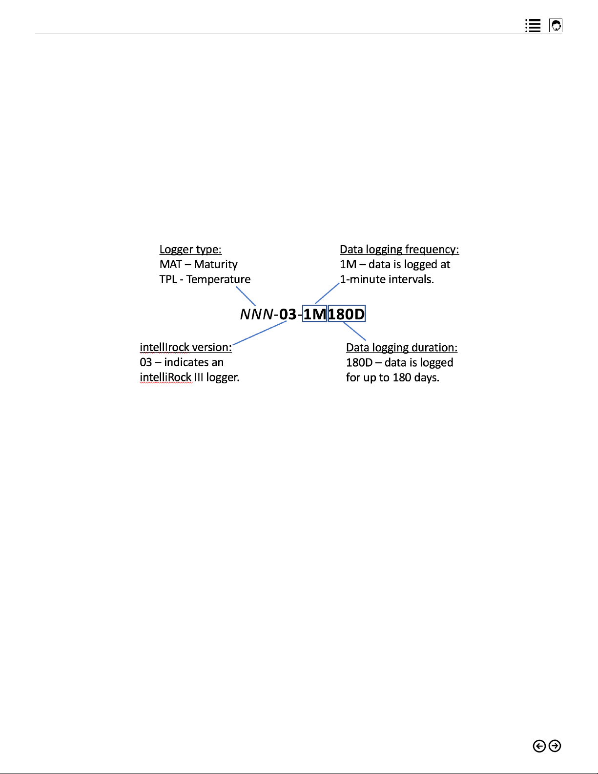
Decoding Logger Part Numbers
The logger part number distinguishes one type of logger from another. While loggers for the
intelliRock III system are now standardized to log at one-minute intervals for up to 180 days, the
part number format for loggers remains consistent from previous generation intelliRock systems. Figure 1.10 shows how to interpret logger part numbers.
Figure 1.10: Interpreting intelliRock logger part number formats.
Logger Types
The part number prefix for maturity loggers is MAT. Two maturity methods are supported by
the intelliRock III system: the Nurse-Saul and Arrhenius method. Always consult with the project engineer to determine which method to use. The method is selectable using the reader
during logger startup, which a later section of this guide will cover.
The part number prefix for temperature loggers is TPL. Temperature loggers will record data
and display readings in °C or °F as specified during logger setup.
Both types of loggers provide assurance of data integrity. After 60 minutes, intelliRock loggers
will record data in uninterruptible mode, and in a format that is unalterable.
11
Page 12

intelliRock® III– Operating Instructions Guide
Reviewing Logger Data
Use the intelliRock III reader to review individual logger data in the field. An easier way to review
logger data is through the intelliRock cloud software. Logger data is uploaded to the cloud by
either:
• Transferring logger data from the reader to the PC software, where it will automatically
upload to the intelliRock cloud software.
• Alternatively, if loggers are connected to the optional intelliRock wireless remote using
cellular connectivity, logger data will automatically upload to the cloud.
The sections of this guide, “Using the intelliRock III Reader”, “Using the intelliRock Cloud Software”, and “Using the intelliRock Wireless Remote” provide further detail on transferring and
reviewing logger data.
Cloud Software Overview
New for the intelliRock III solution, the cloud software serves as the central storage repository
for all logger data, as well as the providing tools for reviewing data and generating reports. Past
intelliRock generations transferred logger data to a PC, where data was provided for review and
in a .CSV file, requiring spreadsheet software to do data analysis. Now logger data is transferred and securely stored in the intelliRock cloud. With intelliRock concrete data now stored in
the cloud, it is accessible from anywhere using a smartphone or through any internet connected computing device with a browser.
In addition to storing all logger data, the intelliRock cloud software provides these functions for
intelliRock III system users:
• Projects: set up, manage, and review projects on which intelliRock III is logging data.
• Calibrations: upload mix calibration data for projects where you will use maturity.
• Users: administer user access to the intelliRock cloud software.
• Settings: set default temperature scale, upload company or project logos, and manage
remote boxes.
• Thermal: view thermal images captured by the intelliRock III thermal camera.
Reference the “Using the intelliRock Cloud Software” section of this guide for complete details
on using the intelliRock cloud.
Wireless Remote Overview
The intelliRock wireless system allows you to connect up to eight of either type of intelliRock
III loggers to the wireless remote box. The wireless remote enables data transfer directly from
placements to the cloud. The wireless remote eliminates the need to visit the placement with
an intelliRock III reader to collect logger data.
Wireless remote connectivity using 900 MHz radio is also supported. As with earlier intelliRock
generations, 900 MHz radio connectivity requires the use of an optional, PC-connected base
12
Page 13

intelliRock technical support: Visit www.flir.com/support or call (866) 276-8369, 9am - 5pm, EST
station. When 900 MHz connectivity is in use, logger data is first transferred to the PC software, and from there goes to the intelliRock cloud.
Reference the “Using the intelliRock Wireless Remote” section of this guide for complete details on using the intelliRock wireless remote.
13
Page 14

intelliRock® III– Operating Instructions Guide
intelliRock III Quick Reference
This quick reference section overviews the key operational aspects of the intelliRock III system.
For full details, refer to the related section of this guide.
intelliRock Reader Setup
1. Power on the intelliRock reader
2. Select the “Setup” (F5) menu option
3. Use the function keys to access and complete reader setup options:
• F1: set display for either PSI or MPa
• F2: set the time and date
• F3: toggle the clock display between 12 and 24-hour mode
• F4: set temperature scales
• F5: access secondary menus
Starting an intelliRock Logger
1. Connect the logger to the intelliRock reader by attaching the logger wires to the terminals on the reader.
2. Power the reader on, or if it is already on, wait for it to establish connection with the logger. For a new logger, the “Run Status” will display “Not Running”.
3. Select the “Logger” (F1) menu option, then the “Start” (F1) menu option.
4. Use the function keys to step through the logger setup screens, making the desired entries for Job Name, Datum, Maturity Method, and Logger Location.
5. After completing logger setup, select the “Save” (F1) menu option to start the logger. The
logger display screen will indicate a “Run Status” of “Running” during the first 60 minutes after logger startup, or “Running Locked” after 60 minutes has elapsed.
Reviewing Logger Data
1. Power the reader on.
2. Connect the logger you wish to review to the reader.
3. After a few seconds, the logger data display screen will appear. If the “psi” display is
zero, it typically means that no calibration mix has yet been associated with the logger.
Consult with the project engineer to know which calibration mix to select to view psi data
for any logger.
4. To associate a calibration mix with the logger, from the logger data display screen select
the “Mix” (F2) menu option. Note: calibration mix curves are uploaded to the reader via
the intelliRock Uploader software.
5. To view a graph of the logger data, select the “Logger” (F1) menu option.
6. The message “Data ready to be read” will appear on the screen. From this screen, select
the “Read” (F4) menu option.
7. A progress bar will appear on the screen, followed by a message, “Logger download
complete” indicating a successful data transfer to the reader.
8. Select the “Graph” (F4) menu option to see a graph of the logger’s data.
14
Page 15

intelliRock technical support: Visit www.flir.com/support or call (866) 276-8369, 9am - 5pm, EST
Downloading Logger Data to the Reader
1. Power the reader on.
2. Connect the logger whose data you wish to transfer to the reader.
3. When the logger data display screen appears, select the “Logger” (F1) menu option.
4. The message “Data ready to be read” will appear on the screen. From this screen, select
the “Read” (F4) menu option.
5. A progress bar will appear on the screen, followed by a message, “Logger download
complete” indicating a successful data transfer to the reader.
6. Disconnect the logger and repeat the process for all loggers whose data you wish to
transfer.
Transferring Data from a Reader to the intelliRock Cloud
1. After downloading logger data to the reader, connect the reader to the PC that is running the intelliRock PC software. Ensure that the reader is powered on.
• If using micro-USB (faster), connect the micro-USB end of the cable to the port on the
bottom of the reader. Connect the USB end of the cable to an available USB port on the
PC.
• If connecting via Bluetooth (slower; Windows 10 only), make sure that the reader is
paired with the PC.
2. In the PC software, click the “Reader” pull down list and select the reader:
• For micro-USB connected readers, the COM port to which the reader is connected will
appear in this list.
• For Bluetooth connected readers, the reader serial number will appear in this list
• If Bluetooth is active and the reader is connected via micro-USB, both the serial number
and COM port will appear in the list.
3. After establishing communication between the reader and the PC, click the “Read and
Upload Logger Data” button. The information window will display the status of the logger
data transfer.
4. After logger data transfer completes, the data will automatically upload to the intelliRock
cloud software if the PC is connected to the internet.
Using the Thermal Camera
1. Turn the reader on and press the FLIR logo button on the keyboard to activate the thermal camera.
2. After the FLIR logo splash screen displays, a live thermal image will appear on screen.
3. Aim the camera at whatever you wish to take a thermal image of, and press the camera
icon button to record the image.
4. Thermal images will upload to the PC and then to the cloud when data transfer is initiated.
15
Page 16
intelliRock® III– Operating Instructions Guide
Using the intelliRock III Reader
To use the intelliRock III reader, press and hold the power button for about three seconds. The
reader should power on and display the splash screen shown in Figure 3.1.
Figure 3.1: The intelliRock III reader splash screen.
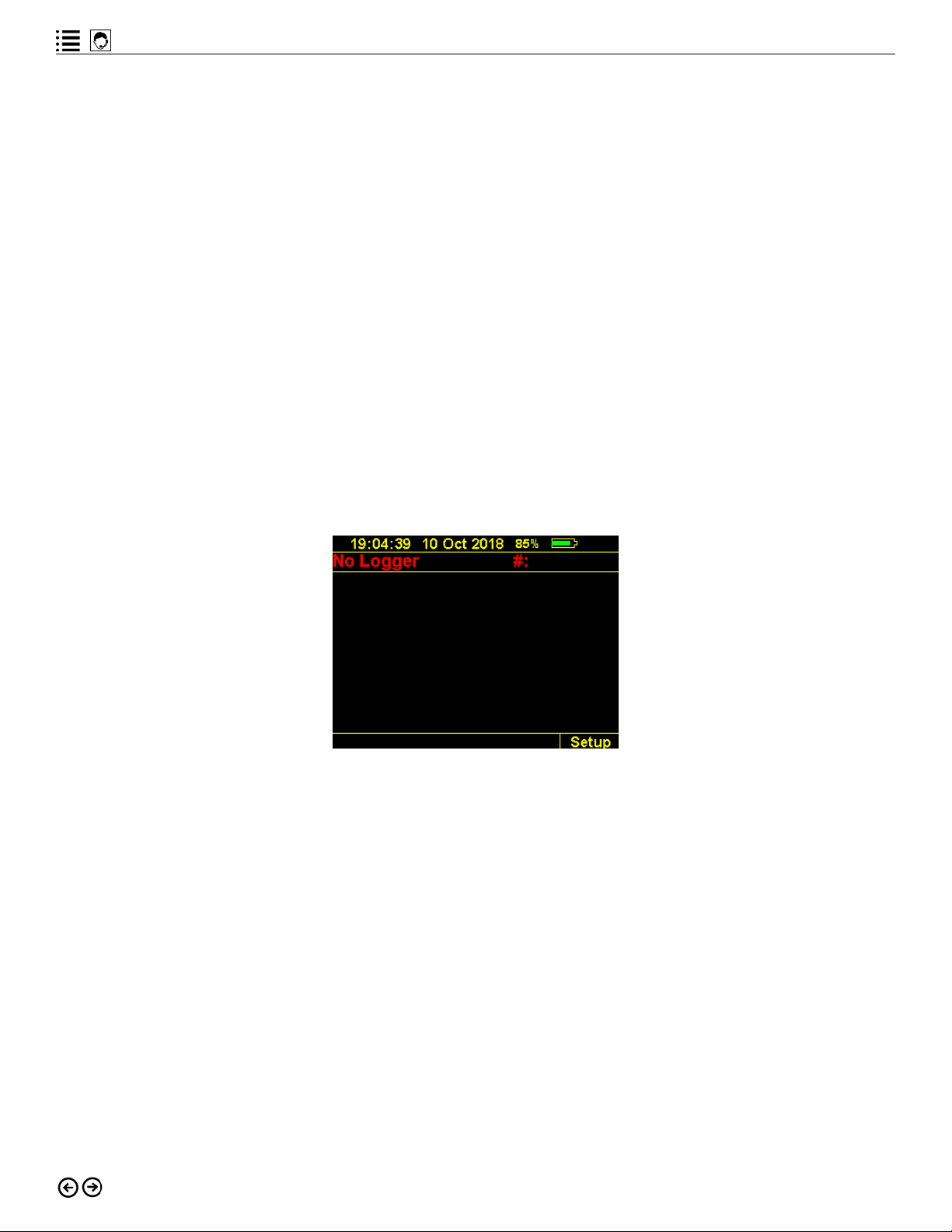
After powering up, the reader will display a screen similar to the one shown in Figure 3.2.
Figure 3.2: Initial display after reader power-up.
The reader display is organized into distinct display areas:
• The top line of the reader screen will display the time, date and battery status.
• The second line of the screen shows the status of any connected logger and its serial number. If no logger is connected to the reader, the display will read “No Logger” as
shown in Figure 3.2.
• The center and largest part of the screen is the main display area. In Figure 3.2, the display area is blank.
• The bottom line of the screen displays the menu options, selectable using the function
keys on the keyboard. In Figure 3.2, the only available menu option is “Setup.”
intelliRock III Reader Setup
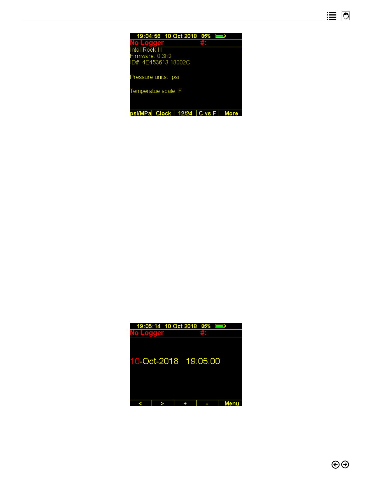
The first time the reader is powered on, you will need to select the Setup (F5) menu option to
enter default settings. The screen shown in Figure 3.3 will appear.
16
Page 17
intelliRock technical support: Visit www.flir.com/support or call (866) 276-8369, 9am - 5pm, EST
Figure 3.3: intelliRock III setup screen.
The setup screen displays the model number, firmware number and ID number of the reader.
The function keys allow setting or changing the settings shown on the bottom line of the display:
• F1: toggle between pressure unit settings, either PSI or MPa
• F2: set the time and date
• F3: toggle the clock display between 12 and 24-hour mode
• F4: toggle between temperature scales
• F5: selecting the “More” menu option will advance to a screen that displays a directory
of logger data files stored on the reader.
These intelliRock reader settings are persistent and are retained through turning the reader off
and on.
Setting the Time and Date
To set the time and date on the intelliRock III reader:
1. Power the unit on and enter the Setup menu as shown in Figure 3.3
2. Press F2 to set the time and date, as shown in Figure 3.4.
Figure 3.4: Setting time and date on the intelliRock III reader.
3. The information highlighted in red is in “edit” mode.
4. Press F3 to increase or F4 to decrease the field that is highlighted in red.
17
Page 18
intelliRock® III– Operating Instructions Guide
5. Move between fields on the screen by pressing F1 (left) or F2 (right).
6. After changing the settings, press the “Menu” (F5) option to return to the home screen.
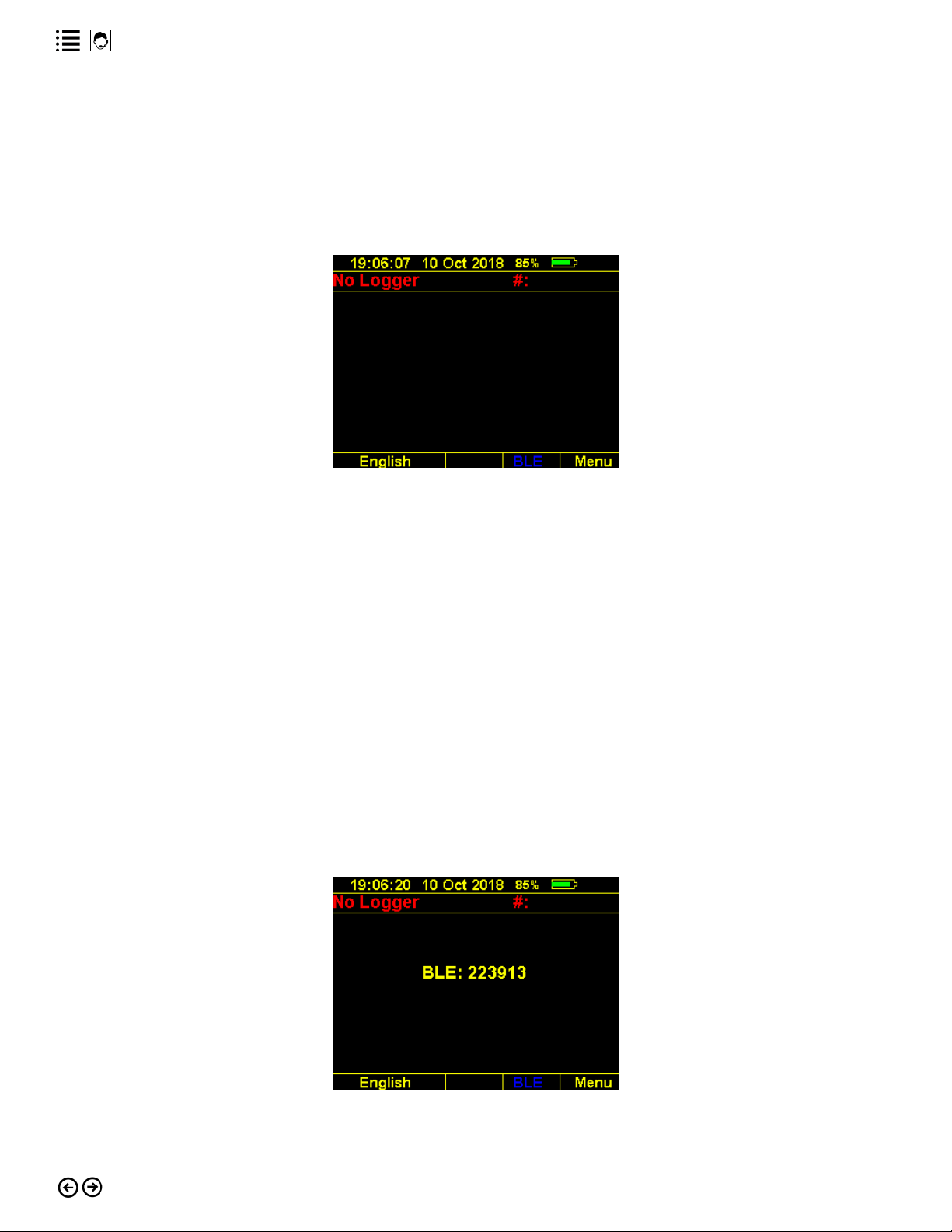
Choosing Language Support
After specifying the time, date, pressure units and temperature scale, the setup menu will allow
the user to toggle between supported languages, as shown in Figure 3.5.
Figure 3.5: Reader home screen after setup.
Use the F1 and F2 to toggle between English and Spanish, the languages currently supported
by the reader.
Establishing Bluetooth Connectivity
The intelliRock III reader supports Bluetooth connectivity to a PC to transfer logger data
from the reader to the PC software, or to transfer mix calibration curves to the reader. To
establish Bluetooth connectivity:
1. Ensure that Bluetooth is enabled on the PC and that the intelliRock PC software is running on that PC (a later section of this guide provides details on using the intelliRock PC
software).
2. From the reader home screen as shown in Figure 3.5, select the Bluetooth menu option
(F4). The screen will display a Bluetooth pairing code as shown in Figure 3.6.
Figure 3.6: A Bluetooth pairing code.
18
Page 19

intelliRock technical support: Visit www.flir.com/support or call (866) 276-8369, 9am - 5pm, EST
3. The reader will generate a new pairing code each time F4 is pressed. Should the initial
pairing attempt fail, press F4 as often as necessary to generate new pairing codes.
Once the reader is successfully paired with a PC using Bluetooth, under normal operations, the
pairing is persistent. However, should the Bluetooth connection fail, simply follow the procedure described in this section to re-establish it.
Select the “Menu” (F5) option to return to the home screen.
Reader Battery Life
Under normal conditions, a fully-charged reader should have enough power for one to two
months of usage. The thermal camera feature, however, consumes substantially more power
and will drain the battery noticeably faster.
The next section of this guide will describe how to use the intelliRock reader to start loggers
and then review the data they collect.
19
Page 20
intelliRock® III– Operating Instructions Guide
Starting and Using Loggers
Starting an intelliRock Logger
To setup and start a logger, connect the wires from the logger you wish to start to the terminals
shown in Figure 1.8 at the top of the intelliRock reader. It does not matter which color wire goes
to which color terminal. Figure 4.1 shows the reader connected to a logger.
Figure 4.1: The intelliRock III reader connected to a logger.
When the logger is successfully connected to the reader, the screen may briefly display the
message “Testing” then “Good Link” before displaying the logger setup screen shown in Figure
4.2.
Figure 4.2: intelliRock startup screen for a new logger.
20
Page 21
intelliRock technical support: Visit www.flir.com/support or call (866) 276-8369, 9am - 5pm, EST
If the logger status on the screen does not indicate “Logger Connected” within a few seconds
of connecting the logger to the reader, disconnect the wires and reconnect them until a good
connection is made.
To setup and start the connected logger, select the “Logger” (F1) menu option, which will cause
the logger start screen as shown in Figure 4.3 to appear.
Figure 4.3: Logger start screen.
To start the connected logger, select the “Start” (F1) menu option, which will open the first of
the logger setup screens, shown in Figure 4.4.
Figure 4.4: Logger setup screen.
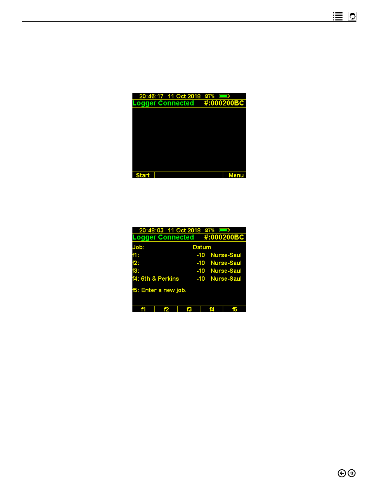
From the first logger setup screen shown in Figure 4.4, first select or specify the name of the
job associated with the logger you are starting. Keys F1 through F4 will display the last four
job names used, if any were specified. For each job name that already stored in the intelliRock
reader, the datum temperature and method for each job is also shown.
Select any of the existing jobs by pressing the associated function key. Or, press F5 to specify
a new job name, datum temperature, and method. These parameters should always be determined by the project engineer.
21
Page 22

intelliRock® III– Operating Instructions Guide
Figure 4.5 shows the logger setup screen for specifying a new job.
Figure 4.5: Setting a logger up for a new job.
The letters displayed in blue text in the center of the screen indicate which data-entry mode
the reader keyboard is in: text or numeric. Toggle between these modes the pressing the “Shift”
key. Using the reader keyboard:
1. Enter the desired job name.
2. Change the datum temperature if necessary by pressing F2 to increase it or F3 to decrease it. Regarding the datum temperature:
• The project engineer should provide the datum temperature.
• When the Nurse-Saul method is selected, datum temperature options are: 0 °C,
• -10 °C, or -20 °C.
• When the Arrhenius method is selected, datum temperature options are presented in
one °C increments.
3. Use the F4 key to select the method: Nurse-Saul, Arrhenius, or temperature.
Note: unlike previous generations of the intelliRock system, which used different loggers
to support either the Nurse-Saul or Arrhenius maturity methods, both methods are
now supported by an intelliRock III maturity logger. Choose the method using the
setup process described above.
When logger setup is complete, press F1 to save the logger configuration, or F5 to abort setup
without saving. Pressing F1 to save the logger configuration will display the screen shown in
Figure 4.6.
Figure 4.6: Saving logger setup information.
22
Page 23

intelliRock technical support: Visit www.flir.com/support or call (866) 276-8369, 9am - 5pm, EST
Important: do not unplug the logger while it is updating, as shown in Figure 4.6.
When the logger has been updated with job information, the reader screen will prompt the user
for logger location information, as shown in Figure 4.7.
Figure 4.7: Entering logger location information.
Use the reader keyboard and follow the same process used to enter the job name to enter the
logger location information. Press F1 to save the logger location, or F5 abort setup without
saving the logger location. After pressing F1 to save the logger location, the screen may temporarily display “Good Link”, “Testing”, or “Updating”.
When logger setup is complete, the screen shown in Figure 4.8 will appear.
Figure 4.8: Logger setup complete screen.
The display shown in Figure 4.8 indicates a Run Status of “Running” indicating that the logger
has started to log data. It also indicates that no calibration mix has yet been uploaded. The job
and location information are displayed, as well as the logger start time and runtime.
After the logger has been running for 60 minutes, the status will change to “Running Locked”
to indicate that the connected logger can no longer be stopped or restarted.
The logger is now running and it is safe to disconnect it from the intelliRock reader. Repeat the
process described in this section to setup and start each logger.
23
Page 24

intelliRock® III– Operating Instructions Guide
Note: for maturity applications, it is not necessary to upload the calibration curve for the job to
each logger at logger startup. Quite often, the calibration curve is created using the same mix
being poured in the placement. Once a calibration curve for a mix is ready, follow the instructions found in a later section of this guide to use that calibration curve with loggers on a specific job. If a calibration curve is available for use with a logger, press F2 to associate it with the
currently connected logger.
Resetting a Logger
The first 60 minutes after starting a logger is an interval during which a user can reset the logger. After this interval is past, the logger becomes locked and can no longer be restarted.
To reset a logger during this period, from the screen shown in Figure 4.8, select the “Logger”
(F1) menu option. The screen shown in Figure 4.9 will appear.
Figure 4.9: Restarting a logger.
From the screen in Figure 4.9, press the “Shift” key and the “Reset” (F1) key simultaneously. The
screen will temporarily display “Updating” before returning to the first logger setup screen.
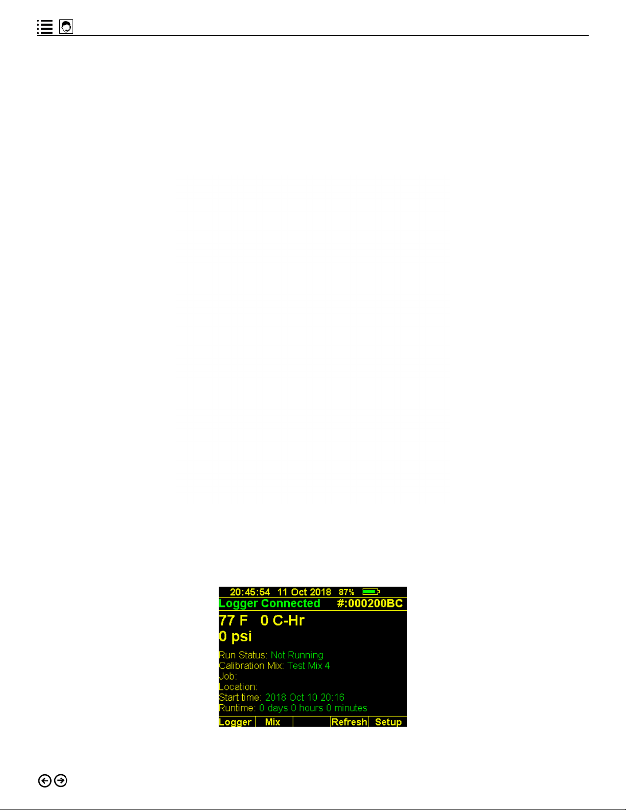
Reviewing Logger Data
To review a logger’s data using the intelliRock reader, connect the logger wires to the reader.
When a logger is successfully connected to the reader, the screen will temporarily display the
“Good Link” message and the serial number of the connected logger as shown in Figure 4.10.
Figure 4.10: The reader screen showing a successful logger connection.
24
Page 25

intelliRock technical support: Visit www.flir.com/support or call (866) 276-8369, 9am - 5pm, EST
If the “Good Link” message is not displayed, disconnect the logger from the reader and reconnect it until a good link is established.
Once a good link is established, it will take a few seconds for the reader to display data from
the logger, and the reader screen will show a green “Logger Connected” message and the display the data shown in Figure 4.11.
Figure 4.11: The logger data display.
Here is how to interpret the data on the screen shown in Figure 4.11:
• The logger data shown in Figure 4.11 displays a current temperature of 77 °F, has accumulated 6878 °C-Hr of maturity, and a PSI of 3546. If the PSI is zero, it means that no
calibration curve has been associated with this logger (Calibration Mix shows “None”).
• The logger job and location name, as entered during the setup process, are shown.
• The logger is currently running with the start time and date shown, with the total runtime.
To learn the PSI of the concrete around where the connected logger was placed, associate a
calibration curve for that concrete mix with the logger:
• The project engineer should provide the calibration curve for the mix in which the logger
is placed.
• A new reader, upon startup, will not have any calibration mixes in the reader, resulting in
a blank “Calibration Mix” field.
• Calibration curves are initially entered into the intelliRock system through the intelliRock
cloud software. Refer to the “intelliRock III Cloud Software” section of this guide for details on using the cloud software.
• Once calibration curves are stored in the intelliRock cloud software, they become available for downloading to the reader.
• During logger startup, the reader will apply the last calibration mix it was told to use for
logger startup.
• Once selected, the calibration mix selection is persistent through power cycling.
25
Page 26

intelliRock® III– Operating Instructions Guide
To select and associate a calibration curve on the reader with a logger that is connected to the
reader, press the F2 to select “Mix” from the screen shown in figure 4.9. Press F2 repeatedly to
cycle through all available calibration curves on the reader. After pausing when the desired calibration curve is selected, the reader screen will update the PSI field, as shown in Figure 4.12.
Figure 4.12: Logger data screen showing PSI data for a selected calibration mix.
Other functions available from the logger data screen shown in Figure 4.12 are:
• Logger (F1): transfer logger data to the reader. Instructions on doing this are covered in
the next section.
• Mix (F2): as described, associate a calibration curve with the connected logger to get a
PSI reading.
• Refresh (F4): refresh the display with the most current logger data.
• Setup (F5): access the logger setup menu, as described in the previous section of this
guide.
Even though the summary data is shown for review on the screen depicted in Figure 4.12, the
data has not been transferred to the intelliRock III reader. Refer to the next section for instructions on transferring and viewing detailed logger data.
Downloading Logger Data to the Reader
After reviewing a logger’s data, the user may wish to transfer that data to the intelliRock III
reader. To do so, from the screen shown in Figure 4.12, press the F1 key for “Logger” which will
start the data transfer. The “Data ready to be read” message shown in Figure 4.13 will appear
on the screen.
Figure 4.13: Data from the connected logger is ready for review and transfer to the reader.
26
Page 27

intelliRock technical support: Visit www.flir.com/support or call (866) 276-8369, 9am - 5pm, EST
The text above the F1 key is a logger status message that will indicate either “Locked” or “Reset”:
• “Locked” means that the logger can no longer be stopped and restarted.
• “Reset” will only appear within the first hour of logger activation and indicates that the
user can stop and restart the logger.
Select the “Read” (F4) menu option to have the reader transfer the data from the logger to the
reader. Press F5 to return to the previous screen.
After pressing the F4 key to read the logger data, a progress bar will briefly appear on the
screen, followed by the confirmation message shown in Figure 4.14.
Figure 4.14: Confirmation message that logger data was transferred to the reader.
This message confirms that the logger data is stored on the reader. When convenient, use the
intelliRock PC software to transfer the data from the reader to the intelliRock cloud software to
enable sharing of data and report generation. Refer to the “intelliRock PC Software” section of
this guide for instructions on getting logger data into the cloud.
The options available to the user from the “Logger download complete” screen are:
• Notes (F3): enter notations related to logger data.
• Graph (F4): view a graph of the logger data.
• Menu (F5): return to the main menu
Entering Logger Data Notes
Loggers can store text notes about conditions and events. For example, a user may wish to
indicate that post-tensioning will occur based on a reading, or that conditions are right to do
the next pour, or to remove forms. To enter notes, press the F3 key. If there are no notes stored
on the logger, the reader will display the message, “No notes are present on this logger.” To add
a note to the logger, select the New (F4) menu option, which will open the notes entry screen
shown in Figure 4.15.
27
Page 28

intelliRock® III– Operating Instructions Guide
Figure 4.15: Entering a note about logger data.
User-entered notes are time and date-stamped. To exit without recording notation text, press
F5 to abort the process.
Viewing Graphs of Logger Data
From the logger download screen shown in Figure 4.14, press the F4 key to view a graph of
logger data. Depending on the amount of data stored on the logger, it may take a few seconds
for the reader to generate the graph. The graph will appear on the reader screen as shown in
Figure 4.16.
Figure 4.16: Graph of data stored on a logger.
All data stored on the logger is shown in the graph. Controls available when viewing the graph
are:
• Scroll left (F1)
• Zoom out (F2)
• Zoom in (F3)
• Scroll right (F4)
• Exit the graph (F5)
The informational shown in blue text just above the graph displays the scrolling increment as a
unit of time where hr stands for hours, M stands for minutes, and d stands for days. The information line also reports the range in units of time that is currently visible on the screen, as
well as the maximum and minimum temperatures for the part of the graph that is visible on the
screen.
28
Page 29

intelliRock technical support: Visit www.flir.com/support or call (866) 276-8369, 9am - 5pm, EST
While viewing and scrolling through the graph, pressing the Shift and Minus (F2) keys simultaneously resets the graph to the initial, default view.
The colors of the lines on the graph help in interpreting the logger data:
• Yellow: the logger temperature line
• Red: strength estimate line. If no calibration mix is associated with the logger, this line
will not display.
• Blue: maturity line
• Green: index line positioned at the center of the reader display. As the user scrolls left or
right, the information displayed just above the menu options shows the readings associated with the green line’s position in the graph.
After viewing the graph, pressing the Menu (F5) key will return the user to the logger data
screen shown in Figure 4.12.
More graphing, reporting and sharing options are available through the intelliRock cloud software.
29
Page 30

intelliRock® III– Operating Instructions Guide
Using the Thermal Camera
New in the intelliRock III system is a lepton, 160 X 120 resolution thermal imaging camera. This
thermal imaging capability enables users to take thermal photos of concrete structures to
visually detect temperature differences. For example, a thermal image can provide evidence of
good coverage in situations where thermal blankets are in use for the thermal protection of the
concrete pour.
To use the thermal camera, press the FLIR logo button. The reader screen will display the FLIR
logo during camera activation as shown in Figure 4.17.
Figure 4.17: Thermal camera startup screen.
It will take the camera a few seconds to normalize the image and calibrate itself after startup.
The camera lens is located on the back of the intelliRock reader, and once the camera is active,
it will display a live, thermal image on the screen of whatever the lens sees.
Pressing the “alt” key on the reader keyboard will cause the camera to cycle through all its
available color palettes as shown in Figure 4.18.
Figure 4.18: Example of the same thermal image using two different color palettes.
After selecting the desired color palette, press the camera icon button to take a thermal image.
Thermal images are initially stored on the intelliRock reader, along with the palette information.
Once thermal images are uploaded to the intelliRock cloud, users have the option of changing
the color palette if desired.
30
Page 31

intelliRock technical support: Visit www.flir.com/support or call (866) 276-8369, 9am - 5pm, EST
After the camera has been running for about a minute, it will display temperature readings,
using the previously selected temperature scale, in three of the corners of the screen as shown
in Figure 4.19.
Figure 4.19: Thermal image screen showing temperature data.
This temperature data is interpreted in the following way:
• The top-left reading displays the temperature of the surface directly below the crosshairs.
• The top-right reading displays the maximum temperature of the surface in the image.
• The bottom-right reading displays the minimum temperature of the surface in the image.
After taking a thermal image, the reader screen will provide the user with the option of entering
a text description to accompany the image. Use the keyboard to enter any desired notation and
then press the F5 key to save the image and notation.
To exit the thermal camera function and return to the main reader menu, press the FLIR logo
button.
Thermal images are stored on the reader, but are viewable only from the intelliRock cloud software. However, to confirm that thermal image files are stored on the reader, use the following
procedure:
1. From the main reader menu shown in Figure 3.2, select “Setup” by pressing the F5 key
2. Select “More” by pressing the F5 key until the “Dir.” appears as a menu option
3. Press the F1 key to access the directory of files on the reader.
31
Page 32

intelliRock® III– Operating Instructions Guide
A screen similar to the one shown in Figure 4.20 will display.
Figure 4.20: Directory of files on the reader.
Files with a suffix of TML are thermal image files. To view them, connect the reader to the intelliRock PC software to transfer the images to the intelliRock cloud software.
32
Page 33

intelliRock technical support: Visit www.flir.com/support or call (866) 276-8369, 9am - 5pm, EST
intelliRock III PC Software
The PC software’s primary function is as a data transfer utility between the reader and the
cloud. It also supports configuration of 900 MHz radio connectivity to intelliRock wireless
remote boxes. For details and instructions on configuring radio support for wireless remote
boxes, reference the “Using the intelliRock III Wireless Remote” section of this guide.
Installing the intelliRock PC software
The intelliRock PC software runs under the Microsoft Windows operating system on an internet-connected PC. Supported versions of Windows are:
• Recommended: Windows 10, version 1709 or higher. This version of Windows 10 is
sometimes referred to as the October 2017 Fall Creator’s Update.
• Also supported. The software will run under Windows 7 with Service Pack 1. However,
Bluetooth connectivity to the intelliRock III reader is not supported under Windows 7.
Make sure you have administrative rights to install software on the PC you will use.
After downloading the intelliRock PC software, double click on the installation file and follow
the instructions to install the software. After installing and running the software for the first
time, the user will receive a login prompt. Enter the User ID and Password information provided
with the system. After logging in, the PC will display the screen shown in Figure 5.1.
Figure 5.1: The intelliRock III PC software home screen.
The intelliRock login credentials, once entered, should persist through opening and closing the
software, eliminating the need to login each time the software is use. To login with different
credentials, so as to access a different intelliRock cloud software account, simply click on the
human head icon located in the upper left corner of the software interface.
33
Page 34

intelliRock® III– Operating Instructions Guide
Once the PC software is open, it will automatically attempt to connect to the intelliRock cloud
software. To enable this connectivity, ensure that the PC is connected to the internet. A warning
message will display if the PC is not connected to the internet.
Connecting the intelliRock III Reader to the PC
With the PC software open, and the reader powered on, connect the intelliRock III reader to the
PC. There are two options for connecting the reader to the PC to transfer data:
1. Bluetooth.
2. Cable. Use the micro-USB port located on the bottom of the reader (see Figure 1.7) to
connect the reader to a USB port on the PC that is running the intelliRock PC software.
As you select an option to connect the reader to the PC, keep in mind that data transfer will
occur much faster when the reader is connected to the PC via the micro-USB cable.
Connecting via Micro USB
Using the micro USB is the fastest way to transfer data from the reader to the PC software. To
do so:
1. Power on the intelliRock III reader.
2. Connect the intelliRock III reader to the PC. The micro USB port is located on the bottom
of the reader (Figure 1.7). Connect the other end of the cable to an available USB port on
the PC that is running the intelliRock PC software.
3. After connecting the reader to the PC, click on the Logger pull-down list, found in the
upper-left area of the PC software window, as shown in Figure 5.2.
Figure 5.2: The reader pull-down list on the PC software home screen.
The reader that is connected via the micro USB cable should appear in the list as a COMN
connected device, where “N” is the port number Windows assigned to the connection. In Figure
5.2, it appears as “COM3”.
The numbers that may also appear in this list represent the serial number of any readers the
software has detected via Bluetooth. As the example in Figure 5.2 shows, the software has
detected an intelliRock III reader through both, supported connection methods.
NOTE: When using the PC software with Windows 10, no driver installation is required.
34
Page 35

intelliRock technical support: Visit www.flir.com/support or call (866) 276-8369, 9am - 5pm, EST
Connecting via Bluetooth
Bluetooth connectivity is only supported when the intelliRock PC software is running on a Windows 10 PC.
To connect a reader via Bluetooth:
1. Make sure Bluetooth connectivity is activated on the PC that is running the intelliRock
PC software.
2. Power on the intelliRock III reader you wish to connect to the PC software.
3. Pair the reader with the PC by starting the PC software and clicking on the Bluetooth
icon in the upper right corner of the screen, which causes a popup window to appear.
The window will display the serial numbers of all readers the PC’s Bluetooth connectivity detects. Enter the pairing code from the reader, as shown in Figure 3.6 into the “BLE
Options” popup as shown in Figure 5.3.
Figure 5.3: Pairing the reader to the PC using Bluetooth.
To connect the reader to the PC software, click on the down arrow shown in Figure 5.2 to pull
down the list of readers the software has detected by either connectivity method. The serial
number(s) of readers detected via Bluetooth will appear in this list. If no readers appear, re-pair
the reader to the PC.
Transferring Logger Data to the PC
After successfully connecting the reader to the PC, click the “Read and Upload Logger Data”
button to commence the transfer of logger data stored on the reader to the PC. The status of
the transfer will appear in the information area located in the right half of the PC software window, as shown in Figure 5.4.
35
Page 36

intelliRock® III– Operating Instructions Guide
Figure 5.4: Transferring logger data from the reader to the PC.
This process will transfer all logger data and thermal image files in the reader’s directory
(Figure 4.18) to the PC. A message will display in the information area to confirm when the data
transfer is complete.
After data is transferred from the reader to the PC software, the software will automatically
then transfer logger and thermal image data to the cloud. Users need not worry about duplicating data, as the intelliRock cloud software distinguishes between new data and duplicate data,
accepting just the data that isn’t already on the cloud.
Transferring Calibrations to the Reader
If the PC that is running the PC software is connected to the internet, and the user is logged in
to the PC software, any calibration mix curves that are stored in the intelliRock cloud software
will appear in the “Calibrations” list. To learn how to upload calibration mix curves to the intelliRock cloud software, refer to the “Using the intelliRock Cloud Software” section of this guide.
To transfer any listed calibration mix curve to the reader, simply check the box by the mix you
wish to transfer, as shown in Figure 5.5.
36
Page 37

intelliRock technical support: Visit www.flir.com/support or call (866) 276-8369, 9am - 5pm, EST
Figure 5.5: Using the PC software to transfer a calibration mix from the cloud to a reader.
After selecting calibration mix curves to transfer, click the “Download Selected Calibrations to
Reader” button found just below the list of calibrations. The status of the transfer will appear in
the information area located in the right half of the PC software window.
Configuring 900 MHz Radio Connectivity for Remote Boxes
Wireless remote boxes, whose function is described in a later section of this guide, are set up
for 900 MHz radio connectivity using the intelliRock PC software.
Wireless remote boxes are available with two options for transferring data from connected
loggers to the intelliRock cloud software:
• Cellular connectivity
• Cellular and 900 MHz radio connectivity
Wireless remote boxes come configured from the factory for one of the two options listed
above. If the use of a wireless remote box will occur in an area with poor or no cellular reception, make sure to purchase wireless remote boxes with configured for 900 MHz radio connectivity.
To set up radio connectivity, first connect an intelliRock wireless remote base station, like the
one shown in Figure 5.6, to the PC that is running the intelliRock PC software.
37
Page 38

intelliRock® III– Operating Instructions Guide
Figure 5.6: The intelliRock wireless remote, 900 MHz base station.
Use the cable provided with the base station and connect it to an available USB port on the PC.
The intelliRock PC software supports connecting no more than one base station.
After connecting the base station to the PC, click to pull down the “Radio Serial Port” list as
shown in Figure 5.7.
Figure 5.7: Radio Serial Port pull-down list showing the base station connected as COM5.
The “Radio Serial Port” pull-down list should show the port to which the wireless remote base
station is connected. Click on that port to select it from the list. Then pull down the “Baud Rate”
list and select “9600” as shown in Figure 5.8.
38
Page 39

intelliRock technical support: Visit www.flir.com/support or call (866) 276-8369, 9am - 5pm, EST
Figure 5.8: Selecting the baud rate for 900 MHz radio connectivity.
After setting the baud rate, click on the “Listen for Remote Boxes” button, which will temporarily gray-out as shown in Figure 5.9 while the base station is detecting wireless remote boxes.
Figure 5.9: Listening for wireless remote boxes.
The base station should detect all wireless remote boxes that are on the same 900 MHz channel and are powered on, and within range, of the base station. A single base station can connect to up to 12 wireless remote boxes simultaneously.
For more information about using intelliRock wireless remote boxes, refer to that section of
this guide.
39
Page 40

intelliRock® III– Operating Instructions Guide
40
Page 41

intelliRock technical support: Visit www.flir.com/support or call (866) 276-8369, 9am - 5pm, EST
Using the intelliRock III Cloud Software
The intelliRock cloud software is new with the intelliRock III system, and it serves as the central
repository for project data, reporting, and data sharing. Data gets to the intelliRock cloud automatically as a result of:
1. Transferring logger data to the intelliRock III reader.
2. Connecting the reader to the intelliRock PC software to transfer stored logger data and
images to the PC.
3. Through wireless remote boxes.
After logger and thermal image data is transferred to the intelliRock PC software, it automatically is uploaded to the intelliRock cloud when the PC is connected to the internet.
Logging in to the intelliRock Cloud
To access the intelliRock cloud, visit the intelliRock website: https://www.intellirock3.com/.
Enter the login credentials provided to you with the purchase of your intelliRock III system into
the screen shown in Figure 6.1.
Figure 6.1: intelliRock cloud login screen.
After logging into the cloud, the home screen, shown in Figure 6.2, will display.
41
Page 42

intelliRock® III– Operating Instructions Guide
Figure 6.2: The intelliRock cloud home screen.
From the home screen, all the functions of the cloud software are accessible. The horizontal
row of buttons across the top of the home screen navigate the user to these cloud software
functions:
1. Projects: Manage existing projects or add new projects.
2. Calibrations: View the calibration mix curves that are stored in the cloud, or upload new
calibrations.
3. Users: Add and administer users.
4. Settings: Set the preferred temperature scale, upload a logo, or manage wireless remote
boxes.
5. Thermal: View and edit thermal image metadata.
From any screen in the cloud software, clicking the “Home” link in the upper right corner will
navigate the user back to the home screen shown in Figure 6.2.
Administering and Managing Users
To add or administer intelliRock cloud users, click on the “Users” button from the cloud home
screen shown in Figure 6.2. The user administration screen shown in Figure 6.3 will appear.
Figure 6.3: The intelliRock cloud user administration screen.
42
Page 43

intelliRock technical support: Visit www.flir.com/support or call (866) 276-8369, 9am - 5pm, EST
A list of all users will appear on this screen. To add a new intelliRock cloud user, click on the
“Add a New User” link found in the upper left corner of the screen.
For existing users, click on either the user name or the blue square containing the pencil icon
to the right of the user’s email address to change:
• User name
• Password
• Associated email address
• User admin level
• User status
Valid admin levels available for users include:
• View only: enables data viewing only.
• User: enables data viewing and adding project, calibration mixes, etc.
• Admin: enables full administrative rights for system and user management.
Admins can set user status to “Active” or “Disabled” to limit access to the intelliRock cloud
without deleting the user.
Creating or Managing Projects in the Cloud
From the home screen in the cloud software, click the “Projects” button to navigate to existing
projects, or to add a new project. The screen shown in Figure 6.4 will appear.
Figure 6.4: The projects home screen.
All existing projects already defined in the intelliRock cloud will appear in the list that appears
in the left column of the screen. The information about projects is organized by project name,
pours associated with that project, and user-entered logger location information entered
during the logger startup process described in Figures 4.4 through 4.6. The way project information is organized on this screen is summarized in Figure 6.5.
43
Page 44

intelliRock® III– Operating Instructions Guide
Figure 6.5: How project information is organized on the projects home screen.
To create or manage a project, click the “Manage Projects” button in the upper left corner of
the screen, which will take you to the screen shown in Figure 6.6.
Figure 6.6: Managing or creating projects in the cloud software.
Add a new project by clicking on the “Add New Project” button, or select an existing project to
manage from the “Choose a Project to Edit” pull-down list, which will navigate you to the screen
shown in Figure 6.7.
Figure 6.7: Editing an existing project in the cloud.
Clicking the “Edit” button by the project or pour name allows the user to edit those names.
Clicking the “Edit” button by the logger name allows the user to edit the name or assign it to
a different pour. Clicking on the red “X” to the right of any project, pour, or logger location will
44
Page 45

intelliRock technical support: Visit www.flir.com/support or call (866) 276-8369, 9am - 5pm, EST
delete it from the cloud, but not from the logger.
From the project editing screen, you can also add a new pour to the project, or to choose a default calibration mix curve to use.
Reviewing Project Data
From the intelliRock cloud home screen, click the “Projects” button to review data. The projects
home screen, as shown in Figure 6.4, will appear. For any project, view the associated data by
checking the box next to any of the logger locations presented in the list. Figure 6.8 shows the
project home screen with one logger location checkbox selected.
Figure 6.8: Reviewing temperature data for a single logger location.
The temperature graph will initially display when one or more logger locations are selected, as
indicated by the blue, highlighted tab just above the graph. To see a different view of the data,
click on a different tab to view a strength graph, the logger data, or any thermal images.
To view the strength graph for one or more logger locations, first select the “Strength Graph”
tab, and then select a calibration mix from the “Choose Calibration” pull-down list located just
below the tabs. Consult with the project engineer to determine which calibration is the proper
one to use. If no calibration mix curves are available, refer to the “Entering New Calibrations”
section of this guide for instructions on uploading calibration mix curves. After choosing a calibration, a graph similar to the one shown in Figure 6.9 will appear.
45
Page 46

intelliRock® III– Operating Instructions Guide
Figure 6.9: A strength graph for a selected calibration mix curve.
Synchronizing Graph Data Based on Logger Start Time
Because loggers are often placed and started at different times on a project, and concrete
often covers sensors at different times, users often want to compare logger data that occurred
at different points in time. The sliding scale feature shown in Figure 6.10 allows you to move
the graph lines of loggers and thus change the temperature comparison that is made. This
feature allows the user to compare more appropriate temperatures and line up data based on
the time concrete covered those loggers.
Figure 6.10: Synchronizing logger data graph display lines based on time.
46
Page 47

intelliRock technical support: Visit www.flir.com/support or call (866) 276-8369, 9am - 5pm, EST
To synchronize the lines on the graph, use the slider controls found immediately below the
X-axis of the graph. The box at the right end of each slider bar shows the amount of offset, in
the same units as the X-axis.
Setting Alerts
Users can set alerts for various events. From the projects home screen, alerts are set using the
“Set a New Alert” pull-down list located just to the right of the “MANAGE PROJECTS” button.
Pulling down the list of alerts shows which alert options are available, as seen in Figure 6.11.
Figure 6.11: Setting an alert.
47
Page 48

intelliRock® III– Operating Instructions Guide
To set an alert, check the box by the logger or loggers for which you want to set an alert. Then
select the type of alert you wish to set from the pull-down list shown in Figure 6.10. For example, selecting a “Strength” alert will cause the strength alert pop-up window to appear, as
shown in Figure 6.12.
Figure 6.12: Strength alert settings pop-up window.
Provide the necessary inputs and make the desired selections in the alert pop-up window and
click the “Set New Alert” button to save the alert.
Viewing and Editing Alerts
Projects for which alerts have been set will display the alert symbol: a triangle with an exclamation point in the center. To view and edit any existing alert, simply click on this symbol. The
symbol for the alert that displays will turn green, and the alert will appear in a green, horizontal
bar just above the graph as shown in Figure 6.13.
48
Page 49

intelliRock technical support: Visit www.flir.com/support or call (866) 276-8369, 9am - 5pm, EST
Figure 6.13: Viewing or editing an alert.
The alert text shown in the green bar is a link, that when clicked, will cause the alert pop-up
window similar to the one shown in Figure 6.12 to appear. From this pop-up window, the user
can set a new alert, update this alert, or delete the alert.
49
Page 50

intelliRock® III– Operating Instructions Guide
Sharing Report Data
From the project home screen (Figure 6.4), reports and graphs are easy to share. Users can
print graphs and data, save them as Excel spreadsheets or PDF files, or share reports via
email. To use any of these options, use the icons located just above and to the right of the
graph, as shown in Figure 6.14.
Figure 6.14: Options for sharing report data.
Click the icon associated with the desired action to print, create report files, or email report
data:
• The printer icon will generate a screen print. Use the landscape orientation to get the
best output.
• The Excel icon will download an Excel spreadsheet containing data from the selected
logger(s).
• The PDF icon will create and download a Concrete Data Report for the selected project
that includes a summary of the selected logger(s) and the graph the user was viewing
when the icon was clicked.
• The email icon will open a pop-up window that allows the user to send a report to any
cloud user.
Calibrations
To manage existing calibrations or to enter new ones, click the “Calibrations” button from the
cloud home screen (Figure 6.2). The calibrations screen will display all calibration mix curves
that are stored in the cloud, similar to what Figure 6.15 shows.
Figure 6.15: Calibrations home screen.
50
Page 51

intelliRock technical support: Visit www.flir.com/support or call (866) 276-8369, 9am - 5pm, EST
Viewing and Managing Existing Calibrations
Click on any calibration shown on the calibration home screen to see the calibration data,
strength calculations, or the calibration graph. Figure 6.16 shows the calibration data screen.
Figure 6.16: Calibration detail screen.
Clicking the “Update Info” link below the column of information to the left of the table allows the
user to update this data.
The default view is for the calibration data. Click the “Strength Calculations” or “Calibration
Graph” to see a different view of the calibration.
For the “Calibration Data” and “Strength Calculations” views, “Edit” and “Delete” functions are
available for each row of data in the calibration table. To add a new row of data to the table, use
the entry fields at the bottom of the table and click “Add” when complete.
An “Export Data to Excel” link below the table allows the user to export the calibration data.
Click the “View All Calibrations” link in the upper right corner of the screen to return to the calibrations home screen.
51
Page 52

intelliRock® III– Operating Instructions Guide
Entering New Calibrations
From the calibration home screen (Figure 6.15), click the “NEW CALIBRATION” button to enter a
new calibration. The screen shown in Figure 6.17 will appear.
Figure 6.17: Entering a new calibration.
A calibration is mix-specific and is developed in the lab through a series of progressive
strength tests on the mixture being calibrated. For this reason, only the project engineer should
provide the calibration mix data for entry into the intelliRock cloud. For a complete explanation
of the calibration process, refer to the appendix of this guide. After obtaining the inputs for
a new calibration as shown in Figure 6.17 from the project engineer, enter them and click the
“Submit Calibration” button
Refer to Figure 5.5 for instructions to transfer calibrations stored in the intelliRock cloud to a
reader.
Managing Cloud Settings and Remote Boxes
From the cloud home screen (Figure 6.2), click the “Settings” button to set basic parameters
for using the cloud software, and to manage intelliRock wireless remote boxes. Figure 6.18
shows the settings home screen.
52
Page 53

intelliRock technical support: Visit www.flir.com/support or call (866) 276-8369, 9am - 5pm, EST
Figure 6.18: Cloud settings home screen.
Change settings as desired. Click the “MANAGE REMOTE BOXES” button to access the list of
intelliRock wireless remote boxes that are setup in the cloud. Figure 6.19 shows how this list will
appear.
Figure 6.19: List of wireless remote boxes visible in the cloud.
53
Page 54

intelliRock® III– Operating Instructions Guide
Each row of the table shown on the screen in Figure 6.19 summarizes the status of the wireless
remote boxes visible to the cloud, including its:
• IMEI number
• Battery level
• Time stamp of last communication
• Elapsed time since last communication
• Communication interval
• Status
The blue button containing the pencil icon found at the end of each wireless remote box summary row allows the user to edit the name of the remote box.
The name of each remote box is a link, and when clicked on, navigates the user to a screen
showing the details for that box, as seen in Figure 6.20.
Figure 6.20: Detailed information for a wireless remote box.
Make any desired changes to wireless remote box name and click “Update Remote Box” when
finished.
Viewing Thermal Images
Thermal images taken with the intelliRock III reader are automatically transferred to the cloud
when the reader is connected to a PC that is running the intelliRock PC software and is connected to the internet.
To view thermal images stored in the cloud, click the “Thermal” button on the cloud home
screen (Figure 6.2). The project list will appear on the screen, as shown in Figure 6.21.
54
Page 55

intelliRock technical support: Visit www.flir.com/support or call (866) 276-8369, 9am - 5pm, EST
Figure 6.21: Viewing thermal images in the cloud.
Click on the project name to see all thermal images associated with a project. Or, click on the
“View Unassigned Thermals” button at the top of the project list column to see unassigned
thermal images.
Each image has an “Edit Thermal N” link below the image, where “N” refers to the image number. Clicking this link opens the edit image pop-up window, shown in Figure 6.22.
Figure 6.22: Editing thermal image assignment data.
Change assignment information for the thermal image as desired and then click the “Update
Thermal” button.
Accessing the intelliRock Cloud from a Smartphone
To gain access to the intelliRock cloud from a smartphone, simply open a browser on the
phone and navigate to the intelliRock cloud software URL: https://www.intellirock3.com/
55
Page 56

intelliRock® III– Operating Instructions Guide
Figure 6.23 shows the intelliRock cloud software login page on a smartphone screen.
Figure 6.23: Accessing the cloud from a smartphone.
The cloud software web interface will adjust to fit the size of the screen size of smartphones or
tablet computers used to access it.
56
Page 57

intelliRock technical support: Visit www.flir.com/support or call (866) 276-8369, 9am - 5pm, EST
Using the intelliRock Wireless Remote
The intelliRock wireless remote box is an optional accessory that enables remote collection of
thermal or strength data from up to eight loggers. It is ideal for use in when logger placements
are distant, remote, or difficult to reach by a user with an intelliRock reader.
The wireless remote is a rugged, weatherproof box that at preset intervals will automatically transmit data from connected loggers to the intelliRock cloud software through an LTE 4G
cellular connection. For areas with poor or no cellular reception, 900 MHz radio connectivity
is also supported and requires the use of the base station accessory shown in Figure 5.6. For
European users, 3G wireless connectivity is available, with 4G planned in the future. However,
900 MHz connectivity is not offered in the European market, but 2.4 GHz is planned.
Figure 7.1: The intelliRock wireless remote box.
Remote boxes will not come from the manufacturer fully charged, so the first thing users
should do is charge the box. Use the cable and charger provided to plug the box into an electrical outlet for charging. The lights on the charger will indicate the charging status as shown in
Figure 7.2.
Figure 7.2: Wireless remote charger with a green light indicating that the box is fully charged.
57
Page 58

intelliRock® III– Operating Instructions Guide
Connecting Loggers to the Wireless Remote Box
To use the intelliRock wireless remote box, first start any loggers you wish to connect to it using the procedure described in the “Starting an intelliRock Logger” section of this guide.
After starting the loggers, connect them to the terminals by threading the logger cables
through the openings on either side of the remote box. It does not matter whether the wireless
remote box is powered on or off when connecting loggers to it. Figure 7.3 shows a side view
of the wireless remote. The gray, foam insert where logger cables pass through is removeable
from the wireless box to facilitate easier cable threading.
Figure 7.3: Side view of the wireless remote box, where logger cables pass through.
Connect each logger cable to one pair of the red and black terminals located inside the wireless remote box. Each pair of connectors is numbered, one through eight. Ensure that the
exposed wire of the logger cable make contact with only one terminal and that both wires of a
logger are connected to a single pair of terminals, not terminals from two different pairs. Secure the connection to the terminal by tightening the connector.
Changing the Wireless Remote Box Name
The Wireless remote boxes will come configured from the manufacturer for use with the purchaser’s intelliRock cloud software account. Each box has a unique IMEI number, a designation
from the cellular communications industry. For new boxes from the manufacturer, the box
name in the cloud will match the IMEI number assigned to that box. The IMEI number is also
the box’s serial number. Figure 7.4 shows the location of the sticker with the serial number. In
the cloud software, users can change the Initial box names to any, desired name.
58
Page 59

intelliRock technical support: Visit www.flir.com/support or call (866) 276-8369, 9am - 5pm, EST
Figure 7.4: Locating the wireless remote box serial number.
To configure the box name to something that is friendlier than the serial number:
1. Power on the wireless remote box.
2. Login to your intelliRock cloud software account.
3. From the cloud home screen (Figure 6.2) click the “Settings” button.
4. From the “Settings” home screen, click the “MANAGE REMOTE BOXES” button.
5. All wireless remote boxes that are associated with the user account, powered on, and
have LTE 4G connectivity should appear in a list shown in Figure 6.17.
6. Click the blue, pencil icon to the right of any listed box to edit its name (Figure 6.18).
Locating the Wireless Remote Box on the Site
When locating the intelliRock wireless remote boxes on a job site, keep in mind that the orientation of the box may affect cellular connectivity. The same principles that apply to having a good
cellular phone connection apply to the wireless remote box. For this reason, do not set the box
on large, metal objects or inside of metal containers.
59
Page 60

intelliRock® III– Operating Instructions Guide
For 900 MHz radio connectivity, communication from the wireless remote box is approximately
line-of-sight. While line-of-sight can cover a long distance, place wireless remote boxes on a
job site maintaining line-of-sight with the base station. Wireless remote boxes that use 900
MHz will act as relays to one another, so line-of-sight to another remote box will also facilitate
good, radio communication.
When closed and latched, the wireless remote box is rainproof. Therefore, there is no need to
place the box in a protective enclosure. Do not, however, place the box in a location where it
could become submerged in water.
Activating the Wireless Remote Box
Wireless remote boxes will come preconfigured from the manufacturer with the purchaser’s
account set up for the box. When the box is powered on, it will automatically establish connectivity to the purchaser’s intelliRock cloud software account using 4G LTE communications.
After connecting loggers that have already been started to the wireless remote box, it will begin
transmitting logger data directly to the cloud at 60-minute intervals.
Setting the Automatic Data Transfer Interval
Wireless remote boxes are configured from the manufacturer to automatically “push” or transfer data to the cloud once an hour. To change this interval:
1. Login to the intelliRock cloud software
2. Click the “Settings” button from the cloud software home screen
3. Click the “MANAGE REMOTE BOXES” button from the “Settings” screen
4. Locate the wireless remote box whose interval you wish to change. Click the up or down
arrow to change the interval.
The new interval will go into effect the next time the box was scheduled to transfer data under
the previous interval.
Using 900 MHz Radio Connectivity for Remote Boxes
Customers can purchase wireless remote boxes in one of two configurations for communicating data:
1. 4G LTE cellular connectivity
2. 4G LTE cellular and 900 MHz radio connectivity
If the use of a wireless remote box will occur in an area with poor or no cellular reception, make
sure to purchase wireless remote boxes configured for 900 MHz radio connectivity.
Wireless remote boxes that use 4G LTE connectivity will automatically transfer data from connected loggers to the cloud.
Boxes that use 900 MHz connectivity will transfer logger data to a base station (Figure 5.6)
60
Page 61

intelliRock technical support: Visit www.flir.com/support or call (866) 276-8369, 9am - 5pm, EST
connected to the PC that is running the intelliRock PC software. A base station can support up
to 12 wireless remote boxes. When using 900 MHz, the wireless remote box transfers data to
the base station, where it is then transferred to the cloud from the PC to which the base station
is connected.
Use the intelliRock PC software to configure 900 MHz radio connectivity for wireless remote
boxes. Refer to “Configuring 900 MHz Radio Connectivity for Remote Boxes” found in the “intelliRock III PC Software” section of this guide.
Manually “Pushing” Data to the Cloud
To manually initiate a “push” of data to the cloud, press the red “Synchronize” button on the
box.
Wireless Remote Box Battery Life
The battery on a fully charged wireless remote box, under normal usage conditions, should
power the box for about 28 days.
61
Page 62

intelliRock® III– Operating Instructions Guide
Placing Loggers in a Structure
When placing loggers in a structure prior to a pour, always consult with the project engineer
about exactly where to place them. In general, best practices for placing loggers include:
• Attach loggers to rebar when possible.
• When attaching loggers to rebar, attach them to the underside of the rebar.
• Do not use wire to attach loggers to rebar or other parts of a structure. Instead, use
plastic zip-ties.
• Place the zip-tie around the logger cable, near the logger, but do not put the zip-tie
around the logger itself.
• Place loggers two to four inches deep from the surface of a placement. Review ASTM
recommendations for details on logger depth.
There is no specification for the number of loggers to use per structure. A good rule of thumb
is to use one logger per 100 to 150 cubic yards of concrete, for flat structures.
Other considerations for determining logger placement and the number of loggers to place
include:
• The type of structure you will pour
• If you will post-tension the structure
• If the structure is exposed to direct sun or shade
In summary, always consult with the engineer-of-record about where to place loggers, and how
many to place.
62
Page 63

intelliRock technical support: Visit www.flir.com/support or call (866) 276-8369, 9am - 5pm, EST
Troubleshooting and Support
To reach intelliRock technical support, call: (866) 276-4435.
The support line is staffed from 9 am to 5 pm, Eastern U.S. time.
The best and most current source of troubleshooting information is found online at:
https://www.flir.com/support-center/Instruments/concrete-curing/
Some of the issues that customers experience using the intelliRock system are summarized
here:
• Reader issues:
• Should the reader not function properly, a hard-reset will often restore proper
functionality. To do a hard reset, simultaneously press and release the: F1, F5, U and
Y keys. The reader will “reboot” and after a minute or two, the intelliRock logo will
appear on the screen as the reader restarts.
• PC software:
• Installation: errors that occur when attempting to install the PC software are often
the result of the user having insufficient rights or permission to install software on
the PC. Contact your company’s PC administrator for help installing the software.
• o Windows version: the intelliRock PC software is supported under Microsoft Windows 10 and Windows 7 running Service Pack 1. While it may work under other
versions of Windows, it is unsupported.
• o USB drivers: Under Windows 10, the correct USB drivers to support connecting
the intelliRock reader should already exist. Under Windows 7, you may need to install the necessary drivers. Make sure that you have the necessary rights or permission to install USB drivers on the PC.
• Loggers:
• Connection to the reader: if the reader is unable to establish a good connection to a
logger, disconnect the logger and reconnect it.
• Resetting a logger: once a logger is running, the user has a 60-minute window after
startup to stop/reset the logger. If the logger status shows “Running Locked,” this
interval has passed and the logger can no longer be reset.
• If the logger is within the reset window, refer to Figure 4.9. To reset the logger, press
the “Shift” key and then select the “Reset” (F1) option.
• Wireless remote boxes:
• Connectivity to the intelliRock Cloud via 4G LTE: if wireless remote boxes do not appear in the cloud software, ensure that the wireless remote box is powered on. Next,
ensure that the box is in a location where there is reliable, 4G LTE cellular service.
Press the “Synchronize” button on the wireless remote box to initiate a manual data
“push” to the intelliRock cloud.
• Connectivity to the PC via 900 MHz radio: make sure the wireless base station is
plugged in to the PC that is running the intelliRock PC software, and that the base
station is turned on. Follow the procedure described in the “Configuring 900 MHz
63
Page 64

intelliRock® III– Operating Instructions Guide
Radio Connectivity for Remote Boxes” section of this guide to establish 900 MHz
radio connectivity with a wireless remote box.
• Logger connectivity: if loggers are connected to the wireless box but no data is
transferred, ensure that the loggers have already been started. If not, disconnect
the logger from the wireless remote and use the reader to start the logger. Reconnect the logger to the wireless remote box. Make sure the box is powered on and
connected via 4G LTE or 900 MHz radio. Press the red “Synchronize” button on the
wireless remote to force a manual data push.
• Cloud software:
• Cloud software access: if the cloud software website is inaccessible, verify that
the URL is correct. If it is, but the cloud software remains inaccessible, contact the
intelliRock technical support team to see if there is a system outage.
• Login/Password: if you need to reset a password, or have forgotten the cloud login
User ID or password, contact the intelliRock technical support team.
If you require further assistance, please contact the intelliRock technical support team at:
(866) 276-4435 between the hours of 9 am and 5 pm, Eastern U.S. time.
Warranty
This product is protected by FLIR’s 1-Year Limited Warranty. Visit www.flir.com/testwarranty to
read the 1-Year Limited Warranty document.
64
Page 65

intelliRock technical support: Visit www.flir.com/support or call (866) 276-8369, 9am - 5pm, EST
Appendix
65
Page 66

intelliRock® III– Operating Instructions Guide
HOW TO DEVELOP A CALIBRATION CURVE
Reference ASTM C 1074 8.1-8.7
A suggested method for developing maturity calibration curve is to cast a minimum of 17 cylinders from a
specified trial batch prior to placing on site concrete. These 17 cylinders will be cast and cured in
accordance with standard procedures for curing specimen cylinders. Two of these 17 cylinders will have
intelliRock maturity loggers placed in them and activated.
IMPORTANT NOTE: All 17 test cylinders must be cured TOGETHER and in the same way:
Embed the intelliRock maturity logger directly in the center of the cylinder. Cure the cylinders per
specifications.
IMPORTANT NOTE: Be sure to activate the intelliRock maturity loggers when cylinders are cast!
To activate loggers follow the procedure below:
1. Attach the leads from the embedded intelliRock maturity logger to the reader.
2. Select F2: Start Logging
3. Select F2: (NONE) or follow the menu instructions to enter the Job Name
4. Select F2: (NONE) or follow the menu instructions to enter a Location Name
5. Press the ‘ENTER’ key to accept the Datum temperature of 0.
6. The logger will return to the main menu. An ‘R’ will display in the upper right hand corner
indicating that the logger is running.
7. You can now disconnect the logger.
66
Page 67

intelliRock technical support: Visit www.flir.com/support or call (866) 276-8369, 9am - 5pm, EST
The 15 cylinders without intelliRock maturity loggers will be broken compressively in groups of three at
five different intervals, or as the project engineer directs.
BREAK THREE CYLINDERS
Each time a set of three cylinders is broken,
two cylinders containing intelliRock maturity loggers. This is done by connecting the logger wires to the
reader and the selecting F1: Current Reading options. Record the resulting strength and maturity
readings.
immediately
take the Current Reading from each of the
TAKE MATURITY READINGS
Using the intelliRock Strength Maturity Spreadsheet input the PSI information from each compressive
break and the corresponding maturity readings taken from the two intelliRock loggers. The spreadsheet
will take that information and plot the first point of the calibration curve.
IMPORTANT NOTE: Download the Strength Maturity Spreadsheet at www.engius.com
Use the intelliRock cloud software to upload calibration data.
.
BreakData
MaturityData
67
Page 68

intelliRock® III– Operating Instructions Guide
Repeat this process at specified intervals to complete the calibration curve. It is up the engineer to
decide when these five break points will occur.
Some examples:
Standard 6 sack mix: 1, 3, 7, 14, 28 days (ASTM C 1074-98 recommended intervals)
High early: 12 hour, 1, 2, 4, 7 days
High early (faster): 4, 6, 8, 12, 24 hours (patching applications)
Slow setting: 7, 14, 28, 42, 56 days
Generally, the maturity data that is of most interest comes from early in the maturity cycle. The expected
strength development of the placed concrete and the strength regions of interest influence the
determination of cylinder break intervals. If extra data points are necessary, additional cylinders can be
cast at the beginning
of the process to create those additional breaks and data points.
When completed the calibration curve represents corresponding strength numbers for each maturity
reading. For example, if it is determined that 4300 degree CH corresponds to 3000 PSI, then during the
curing process the engineer is looking for maturity of 4300 degree CH in order to proceed with
construction activities, e.g. opening to construction, sawing, post-tensioning, stripping of forms
and reshoring or other activities.
68
Page 69

intelliRock technical support: Visit www.flir.com/support or call (866) 276-8369, 9am - 5pm, EST
Corporate Headquarters
FLIR Systems, Inc.
2770 SW Parkway Avenue
Wilsonville, OR 97070 USA
Customer Support
Repair, Calibration, and Technical Support:: https://support.flir.com
69
 Loading...