

Page 1
User’s manual – Benutzerhandbuch – Manual del usuario – Manuel de l’utilisateur – Manuale dell’utente – Manual do utilizador – Felhas-
ználói kézikönyv – Käyttäjän opas –
Betjeningsvejledning – Brukerveiledning – Instrukcja obsługi – Bruksanvisning – Kullanım
Kılavuzu – Uživatelská příručka –
Gebruikershandleiding
User’s manual
InfraCAM
InfraCAM SD
1558299Publ. No.
a200Revision
English (EN)Language
February 12, 2007Issue date
Page 2

Page 3

Warnings & Cautions
1
Notice to user
Important note about this manual
Contents of the transport case
Camera parts
Screen elements
Connecting the cables
Operating the camera
Cleaning the camera
Technical data
2
3
4
5
6
7
8
9
10
Dimensional drawings
Introduction to building thermography
Introduction to thermographic inspections of
electrical installations
About FLIR Systems
History of infrared technology
11
12
13
14
15
Page 4

Page 5

Index
16
Page 6

Page 7

User’s manual
Publ. No. 1558299 Rev. a200 – ENGLISH (EN) – February 12, 2007
Page 8

Legal disclaimer
All products manufactured by FLIR Systems are warranted against defective materials and workmanship for a period of one (1) year from the
delivery date of the original purchase, provided such products have been under normal storage, use and service, and in accordance with
FLIR Systems instruction.
All products not manufactured by FLIR Systems included in systems delivered by FLIR Systems to the original purchaser carry the warranty,
if any, of the particular supplier only and FLIR Systems has no responsibility whatsoever for such products.
The warranty extends only to the original purchaser and is not transferable. It is not applicable to any product which has been subjected to
misuse, neglect, accident or abnormal conditions of operation. Expendable parts are excluded from the warranty.
In the case of a defect in a product covered by this warranty the product must not be further used in order to prevent additional damage. The
purchaser shall promptly report any defect to FLIR Systems or this warranty will not apply.
FLIR Systems will, at its option, repair or replace any such defective product free of charge if, upon inspection, it proves to be defective in
material or workmanship and provided that it is returned to FLIR Systems within the said one-year period.
FLIR Systems has no other obligation or liability for defects than those set forth above.
No other warranty is expressed or implied. FLIR Systems specifically disclaims the implied warranties of merchantability and fitness for a
particular purpose.
FLIR Systems shall not be liable for any direct, indirect, special, incidental or consequential loss or damage, whether based on contract, tort
or any other legal theory.
Copyright
© FLIR Systems,2007. All rights reservedworldwide. No parts of thesoftware including source code maybe reproduced, transmitted, transcribed
or translated into any language or computer language in any form or by any means, electronic, magnetic, optical, manual or otherwise,
without the prior written permission of FLIR Systems.
This manual must not, in whole or part, be copied, photocopied, reproduced, translated or transmitted to any electronic medium or machine
readable form without prior consent, in writing, from FLIR Systems.
Names and marks appearing on the products herein are either registered trademarks or trademarks of FLIR Systems and/or its subsidiaries.
All other trademarks,trade names or companynames referenced herein areusedfor identification only andarethe property of theirrespective
owners.
Quality assurance
The Quality Management System under which these products are developed and manufactured has been certified in accordance with the
ISO 9001 standard.
FLIR Systems is committed to a policy of continuous development; therefore we reserve the right to make changes and improvements on
any of the products described in this manual without prior notice.
Patents
This product is protected by patents, design patents, patents pending, or design patents pending.
One or several of the following patents, design patents, patents pending, or design patents pending apply to the products and/or features
described in this manual:
Reg. No.StatusDesignation
00809178.1ApplicationChina
01823221.3ApplicationChina
01823226.4ApplicationChina
235308Design PatentChina
ZL02331553.9Design PatentChina
ZL02331554.7Design PatentChina
200530018812.0PendingChina
1188086PatentEPC
01930377.5ApplicationEPO
01934715.2ApplicationEPO
27282912ApplicationEPO
000279476-0001Design PatentEU
1188086PatentFrance
viii Publ. No. 1558299 Rev. a200 – ENGLISH (EN) – February 12, 2007
Page 9

Reg. No.StatusDesignation
60004227.8PatentGermany
106017Design PatentGreat Britain
3006596Design PatentGreat Britain
3006597Design PatentGreat Britain
1188086PatentGreat Britain
DM/057692Design PatentInternational
DM/061609Design PatentInternational
2000-620406ApplicationJapan
2002-588123ApplicationJapan
2002-588070ApplicationJapan
1144833Design PatentJapan
1182246Design PatentJapan
1182620Design PatentJapan
2005-020460PendingJapan
PCT/SE01/00983ApplicationPCT
PCT/SE01/00984ApplicationPCT
PCT/SE02/00857ApplicationPCT
PCT/SE03/00307ApplicationPCT
PCT/SE/00/00739ApplicationPCT
0302837-0ApplicationSweden
68657Design PatentSweden
75530Design PatentSweden
518836PatentSweden
522971PatentSweden
524024PatentSweden
09/576266ApplicationU.S.
10/476,760ApplicationU.S.
466540Design PatentU.S.
483782Design PatentU.S.
484155Design PatentU.S.
5,386,117PatentU.S.
5,637,871PatentU.S.
5,756,999PatentU.S.
6,028,309PatentU.S.
6,707,044PatentU.S.
6,812,465PatentU.S.
7,034,300PatentU.S.
Publ. No. 1558299 Rev. a200 – ENGLISH (EN) – February 12, 2007
Page 10

Reg. No.StatusDesignation
29/233,400PendingU.S.
EULA Terms
You have acquired a device (“INFRARED CAMERA”) that includes software licensed by FLIR Systems AB from Microsoft Licensing, GP
■
or its affiliates (“MS”). Those installed software products of MS origin, as well as associated media, printed materials, and “online” or
electronic documentation (“SOFTWARE”)are protected by international intellectualproperty laws and treaties. TheSOFTWARE is licensed,
not sold. All rights reserved.
IF YOU DO NOT AGREE TO THIS END USER LICENSE AGREEMENT (“EULA”), DO NOT USE THE DEVICE OR COPY THE SOFTWARE.
■
INSTEAD, PROMPTLY CONTACT FLIR Systems AB FOR INSTRUCTIONS ON RETURN OF THE UNUSED DEVICE(S) FOR A REFUND.
ANY USE OF THE SOFTWARE, INCLUDING BUT NOT LIMITED TO USE ON THE DEVICE, WILL CONSTITUTE YOUR AGREEMENT
TO THIS EULA (OR RATIFICATION OF ANY PREVIOUS CONSENT).
GRANT OF SOFTWARE LICENSE. This EULA grants you the following license:
■
You may use the SOFTWARE only on the DEVICE.
■
NOT FAULT TOLERANT. THE SOFTWARE IS NOT FAULT TOLERANT. FLIR Systems AB HAS INDEPENDENTLY DETERMINED
■
HOW TO USE THE SOFTWARE IN THE DEVICE, AND FLIR Systems AB HAS RELIED UPON FLIR Systems AB TO CONDUCT SUFFICIENT TESTING TO DETERMINE THAT THE SOFTWARE IS SUITABLE FOR SUCH USE.
NO WARRANTIES FOR THE SOFTWARE. THE SOFTWARE is provided “AS IS” and with all faults. THE ENTIRE RISK AS TO SAT-
■
ISFACTORY QUALITY, PERFORMANCE, ACCURACY, AND EFFORT (INCLUDING LACK OF NEGLIGENCE) IS WITH YOU. ALSO,
THERE ISNO WARRANTY AGAINSTINTERFERENCE WITH YOURENJOYMENT OF THESOF TWAREOR AGAINST INFRINGEMENT.
IF YOU HAVE RECEIVED ANY WARRANTIES REGARDING THE DEVICE OR THE SOFTWARE, THOSE WARRANTIES DO NOT
ORIGINATE FROM, AND ARE NOT BINDING ON, FLIR Systems AB.
No Liability for Certain Damages. EXCEPT AS PROHIBITED BY LAW, FLIR Systems AB SHALL HAVE NO LIABILITY FOR ANY
■
INDIRECT, SPECIAL, CONSEQUENTIAL OR INCIDENTAL DAMAGES ARISING FROM OR IN CONNECTION WITH THE USE
OR PERFORMANCE OF THE SOF TWARE. THIS LIMITATION SHALL APPLY EVEN IF ANY REMEDY FAILS OF ITS ESSENTIAL
PURPOSE. IN NO EVENT SHALL FLIR Systems AB BE LIABLE FOR ANY AMOUNT IN EXCESS OF U.S. TWO HUNDRED FIFTY
DOLLARS (U.S.$250.00).
Limitations on Reverse Engineering, Decompilation, and Disassembly. You maynot reverse engineer,decompile, or disassemble
■
the SOFTWARE, exceptand only to the extentthat such activity is expresslypermitted by applicable law notwithstandingthis limitation.
SOFTWARE TRANSFER ALLOWED BUT WITH RESTRICTIONS. You may permanently transferrights under this EULA only as part
■
of a permanent sale or transfer of the Device, and only if the recipient agrees to this EULA. If the SOF TWARE is an upgrade, any
transfer must also include all prior versions of the SOFTWARE.
EXPORT RESTRICTIONS. You acknowledge that SOFTWARE is subject to U.S. export jurisdiction. You agree to comply with all
■
applicable international and national laws that apply to the SOFTWARE, includingthe U.S. Export Administration Regulations, as well
as end-user, end-use and destination restrictions issued by U.S. and other governments. For additional information see
http://www.microsoft.com/exporting/.
x Publ. No. 1558299 Rev. a200 – ENGLISH (EN) – February 12, 2007
Page 11

Table of contents
8.3.1 Using the combined power supply & battery charger to charge the battery when
it is inside the camera ...........................................................................................
8.3.2 Using the combined power supply & battery charger to charge the battery when
it is outside the camera .........................................................................................
8.10.3 Changing both the maximum and minimum temperature level at the same
time .......................................................................................................................
11 Warnings & Cautions .....................................................................................................................
42 Notice to user ..................................................................................................................................
73 Important note about this manual .................................................................................................
94 Contents of the transport case .....................................................................................................
115 Camera parts ...................................................................................................................................
115.1 Front view .............................................................................................................................
135.2 Side view ...............................................................................................................................
145.3 Keypad ..................................................................................................................................
155.4 Controls & functions .............................................................................................................
165.5 Power indicator .....................................................................................................................
175.6 Battery condition indicator ...................................................................................................
185.7 Laser pointer .........................................................................................................................
206 Screen elements .............................................................................................................................
237 Connecting the cables ...................................................................................................................
237.1 Power cable ..........................................................................................................................
247.2 USB cable .............................................................................................................................
258 Operating the camera ....................................................................................................................
258.1 Installing the battery .............................................................................................................
268.2 Removing the battery ...........................................................................................................
278.3 Charging the battery .............................................................................................................
28
29
308.3.3 Using the stand-alone battery charger to charge the battery ..............................
318.4 Starting the camera ..............................................................................................................
318.5 Stopping the camera ............................................................................................................
328.6 Adjusting camera focus ........................................................................................................
338.7 Operating the laser pointer ...................................................................................................
348.8 Saving an image ...................................................................................................................
368.9 Auto-adjusting an image ......................................................................................................
378.10 Adjusting an image manually ...............................................................................................
388.10.1 Increasing or decreasing the maximum temperature level ..................................
398.10.2 Increasing or decreasing the minimum temperature level ..................................
40
418.11 Measuring a temperature using a spot meter ......................................................................
428.12 Measuring a temperature using an area ..............................................................................
438.13 Changing the colors .............................................................................................................
448.14 Changing emissivity .............................................................................................................
468.15 Changing the reflected apparent temperature ....................................................................
488.16 Opening an image ................................................................................................................
498.17 Deleting an image .................................................................................................................
508.18 Deleting all images ...............................................................................................................
Publ. No. 1558299 Rev. a200 – ENGLISH (EN) – February 12, 2007 xi
Page 12

12.2.1.2 Guidelines for moisture detection, mold detection & detection of
water damages ..................................................................................
518.19 Changing camera settings ...................................................................................................
528.20 Moving images to a PC ........................................................................................................
548.21 Viewing streaming MPEG4 live video from the camera .......................................................
559 Cleaning the camera ......................................................................................................................
559.1 Camera housing, cables & other items ................................................................................
569.2 Infrared lens ..........................................................................................................................
5710 Technical data .................................................................................................................................
6311 Dimensional drawings ...................................................................................................................
6311.1 Camera .................................................................................................................................
6711.2 Battery ...................................................................................................................................
6811.3 Stand-alone battery charger .................................................................................................
6911.4 Stand-alone battery charger with battery .............................................................................
7112 Introduction to building thermography ........................................................................................
7112.1 Important note ......................................................................................................................
7112.2 Typical field investigations ....................................................................................................
7112.2.1 Guidelines .............................................................................................................
7112.2.1.1 General guidelines ............................................................................
72
7212.2.1.3 Guidelines for detection of air infiltration & insulation deficiencies ...
7312.2.2 About moisture detection .....................................................................................
7312.2.3 Moisture detection (1): Low-slope commercial roofs ..........................................
7312.2.3.1 General information ...........................................................................
7412.2.3.2 Safety precautions ............................................................................
7512.2.3.3 Commented building structures .......................................................
7612.2.3.4 Commented infrared images ............................................................
7812.2.4 Moisture detection (2): Commercial & residential façades ..................................
7812.2.4.1 General information ...........................................................................
7812.2.4.2 Commented building structures .......................................................
8012.2.4.3 Commented infrared images ............................................................
8012.2.5 Moisture detection (3): Decks & balconies ..........................................................
8012.2.5.1 General information ...........................................................................
8112.2.5.2 Commented building structures .......................................................
8312.2.5.3 Commented infrared images ............................................................
8312.2.6 Moisture detection (4): Plumbing breaks & leaks ................................................
8312.2.6.1 General information ...........................................................................
8412.2.6.2 Commented infrared images ............................................................
8612.2.7 Air infiltration .........................................................................................................
8612.2.7.1 General information ...........................................................................
8612.2.7.2 Commented building structures .......................................................
8812.2.7.3 Commented infrared images ............................................................
8912.2.8 Insulation deficiencies ..........................................................................................
8912.2.8.1 General information ...........................................................................
8912.2.8.2 Commented building structures .......................................................
9112.2.8.3 Commented infrared images ............................................................
9312.3 Theory of building science ...................................................................................................
9312.3.1 General information ..............................................................................................
9412.3.2 The effects of testing and checking .....................................................................
9512.3.3 Sources of disruption in thermography ................................................................
9712.3.4 Surface temperature and air leaks .......................................................................
xii Publ. No. 1558299 Rev. a200 – ENGLISH (EN) – February 12, 2007
Page 13

9712.3.4.1 Pressure conditions in a building .....................................................
10312.3.5 Measuring conditions & measuring season .........................................................
10312.3.6 Interpretation of infrared images ..........................................................................
10512.3.7 Humidity & dew point ...........................................................................................
10512.3.7.1 Relative & absolute humidity ............................................................
10612.3.7.2 Definition of dew point ......................................................................
10612.3.8 Assessing thermal bridging and insulation continuity .........................................
10612.3.8.1 Credits ...............................................................................................
10712.3.8.2 Introduction .......................................................................................
10712.3.8.3 Background information ...................................................................
10812.3.8.4 Quantitative appraisal of thermal anomalies ....................................
11212.3.8.5 Conditions and equipment ...............................................................
11312.3.8.6 Survey and analysis ..........................................................................
11412.3.8.7 Reporting ...........................................................................................
11612.4 Disclaimer .............................................................................................................................
11612.4.1 Copyright notice ...................................................................................................
11612.4.2 Training & certification ..........................................................................................
11612.4.3 National or regional building codes .....................................................................
11713 Introduction to thermographic inspections of electrical installations ......................................
11713.1 Important note ......................................................................................................................
11713.2 General information ..............................................................................................................
11713.2.1 Introduction ...........................................................................................................
11813.2.2 General equipment data .......................................................................................
11913.2.3 Inspection .............................................................................................................
11913.2.4 Classification & reporting ......................................................................................
12013.2.5 Priority ...................................................................................................................
12013.2.6 Repair ....................................................................................................................
12113.2.7 Control ..................................................................................................................
12213.3 Measurement technique for thermographic inspection of electrical installations ...............
12213.3.1 How to correctly set the equipment .....................................................................
12213.3.2 Temperature measurement ...................................................................................
12413.3.3 Comparative measurement ..................................................................................
12513.3.4 Normal operating temperature .............................................................................
12613.3.5 Classification of faults ...........................................................................................
12813.4 Reporting ..............................................................................................................................
13013.5 Different types of hot spots in electrical installations ...........................................................
13013.5.1 Reflections ............................................................................................................
13013.5.2 Solar heating .........................................................................................................
13113.5.3 Inductive heating ...................................................................................................
13113.5.4 Load variations ......................................................................................................
13213.5.5 Varying cooling conditions ...................................................................................
13313.5.6 Resistance variations ............................................................................................
13313.5.7 Overheating in one part as a result of a fault in another ......................................
13513.6 Disturbance factors at thermographic inspection of electrical installations ........................
13513.6.1 Wind ......................................................................................................................
13513.6.2 Rain and snow ......................................................................................................
13613.6.3 Distance to object .................................................................................................
13713.6.4 Object size ............................................................................................................
13913.7 Practical advice for the thermographer ................................................................................
13913.7.1 From cold to hot ...................................................................................................
13913.7.2 Rain showers ........................................................................................................
13913.7.3 Emissivity ..............................................................................................................
Publ. No. 1558299 Rev. a200 – ENGLISH (EN) – February 12, 2007 xiii
Page 14

14013.7.4 Reflected apparent temperature ...........................................................................
14013.7.5 Object too far away ...............................................................................................
14114 About FLIR Systems .......................................................................................................................
14214.1 More than just an infrared camera .......................................................................................
14214.2 Sharing our knowledge ........................................................................................................
14214.3 Supporting our customers ...................................................................................................
14314.4 A few images from our facilities ...........................................................................................
14515 History of infrared technology ......................................................................................................
149Index ................................................................................................................................................
xiv Publ. No. 1558299 Rev. a200 – ENGLISH (EN) – February 12, 2007
Page 15

1 Warnings & Cautions
This equipment generates, uses, and can radiate radio frequency energy and if
WARNING
■
not installed and used in accordance with the instruction manual, may cause interference to radio communications. It has been tested and found to comply with
the limits for a Class A computing device pursuant to Subpart J of Part 15 of FCC
Rules, which are designed to provide reasonable protection against such interference when operated in a commercial environment. Operation of this equipment
in a residential area is likely to cause interference in which case the user at his
own expense will be required to take whatever measures may be required to
correct the interference.
(Applies only to cameras with laser pointer:) Do not look directly into the laser
■
beam. The laser beam can cause eye irritation.
Do not disassemble or do a modification to the battery. The battery contains
■
safety and protection devices which, if they become damaged, can cause the
battery to become hot, or cause an explosion or an ignition.
If there is a leak from the battery and the fluid gets into your eyes, do not rub your
■
eyes. Flush well with water and immediately get medical care. The battery fluid
can cause injury to your eyes if you do not do this.
Do not continue to charge the battery if it does not become charged in the specified
■
charging time. If you continue to charge the battery, it can become hot and cause
an explosion or ignition.
Only use the correct equipment to discharge the battery. If you do not use the
■
correct equipment, you can decrease the performance or the life cycle of the
battery. If you do not use the correct equipment, an incorrect flow of current to
the battery can occur. This can cause the battery to become hot, or cause an explosion and injury to persons.
Make sure that you read all applicable MSDS (Material Safety Data Sheets) and
■
warning labels on containers before you use a liquid. The liquids can be dangerous.
1
Do not point the infrared camera (with or without the lens cover) at intensive energy
CAUTION
■
sources, for example devices that emit laser radiation, or the sun for a long period
of time. This can have an unwanted effect on the accuracy of the camera. It can
also cause damage to the detector in the camera.
Do not use the camera in a temperature higher than +50°C (+122°F), unless
■
specified otherwise in the technical data section. High temperatures can cause
damage to the camera.
(Applies only to cameras with laser pointer:) Protect the laser pointer with the
■
protective cap when you do not operate the laser pointer.
Do not attach the batteries directly to a car’s cigarette lighter socket.
■
Do not connect the positive terminal and the negative terminal of the battery to
■
each other with a metal object (such as wire).
Do not get water or salt water on the battery, or permit the battery to get wet.
■
Do not make holes in the battery with objects.Do not hit the battery with a hammer.
■
Do not step on the battery, or apply strong impacts or shocks to it.
Do not put the batteries in or near a fire, or into direct sunlight. When the battery
■
becomes hot, the built-in safety equipment becomes energized and can stop the
battery charging process. If the battery becomes hot, damage can occur to the
safety equipment and this can cause more heat, damage or ignition of the battery.
Publ. No. 1558299 Rev. a200 – ENGLISH (EN) – February 12, 2007 1
Page 16

1 – Warnings & Cautions
1
Do not put the battery on a fire or increase the temperature of the battery with
■
heat.
Do not put the battery on or near fires, stoves, or other high-temperature locations.
■
Do not solder directly onto the battery.
■
Do not use the battery if, when you use, charge, or store the battery, there is an
■
unusual smell from the battery, the battery feels hot, changes color, changes
shape, or is in an unusual condition. Contact your sales office if one or more of
these problems occurs.
Only use a specified battery charger when you charge the battery.
■
The temperature range through which you can charge the battery is ±0°C to
■
+45°C (+32°F to +113°F). If you charge the battery at temperatures out of this
range, it can cause the battery to become hot or to break. It can also decrease
the performance or the life cycle of the battery.
The temperature range through which you can discharge the battery is −15°C to
■
+50°C (+5°F to +122°F). Use of the battery out of this temperature range can
decrease the performance or the life cycle of the battery.
When the battery is worn, apply insulation to the terminals with adhesive tape or
■
similar materials before you discard it.
Do not use thinner or an equivalent liquid on the camera, the cables and other
■
items. This can cause damage.
Be careful when you clean the infrared lens. The lens has an anti-reflective coating.
■
Do not clean the infrared lens too much. Thiscan cause damage tothe anti-reflec-
■
tive coating.
2 Publ. No. 1558299 Rev. a200 – ENGLISH (EN) – February 12, 2007
Page 17

INTENTIONALLY LEFT BLANK
1 – Warnings & Cautions
1
Publ. No. 1558299 Rev. a200 – ENGLISH (EN) – February 12, 2007 3
Page 18

2 Notice to user
2
Typographical
conventions
This manual uses the following typographical conventions:
Semibold is used for menu names, menu commands and labels and buttons in
■
dialog boxes.
Italic is used for important information.
■
Monospace is used for code samples.
■
UPPERCASE is used for names on keys and buttons.
■
Comments &
questions
Technical support
Software updates
Make a report of errors you find, as well as your suggestions for new revisions. Send
an e-mail to:
documentation@flir.se
To get technical support, visit this site:
http://flir.custhelp.com
To submit a question to the technical support team you must be a registered user.
It only takes a few minutes to register online. If you only want to search the knowledgebase for existing questions and answers, you do not need to be a registered
user.
When you want to submit a question, make sure that you have the following information on hand:
The camera model name
■
The camera serial number
■
The communication protocol, or method, between the camera and your PC (for
■
example, Ethernet, USB, or FireWire)
Operating system on your PC
■
Microsoft® Office version
■
Full name, publication number and revision number of the manual
■
FLIR Systems regularly issues software upgrades and service releases on the support
pages of the company website:
http://www.flirthermography.com
To find the latest upgrades and service releases, make sure you select USA in the
Select country box in the top right corner of the page.
Calibration
(This notice only applies to cameras with measurement capabilities:)
We recommend that you send in the camera for calibration one time per year. Contact
your local sales office for instructions where to send the camera.
Accuracy
(This notice only applies to cameras with measurement capabilities:)
For very accurate results, we recommend that you wait 5 minutes after you have
started the camera before you measure a temperature.
4 Publ. No. 1558299 Rev. a200 – ENGLISH (EN) – February 12, 2007
Page 19

2 – Notice to user
Disposal of
electronic waste
Training
10742803;a1
2
As with most electronic products, this equipment must be disposed of in an environmentally friendly way, and in accordance with existing regulations for electronic waste.
Please contact your FLIR Systems representative for more details.
To read about infrared training, visit this site:
http://www.infraredtraining.com
Publ. No. 1558299 Rev. a200 – ENGLISH (EN) – February 12, 2007 5
Page 20

2 – Notice to user
2
INTENTIONALLY LEFT BLANK
6 Publ. No. 1558299 Rev. a200 – ENGLISH (EN) – February 12, 2007
Page 21

3 Important note about this manual
General
NOTE
FLIR Systems issues generic manuals that cover several cameras within a model
line.
This means that this manual contains descriptions and explanations that may not
apply to your particular camera model.
FLIR Systems reserves the right to discontinue models, parts or accessories, and
other items, or change specifications at any time without prior notice.
3
Publ. No. 1558299 Rev. a200 – ENGLISH (EN) – February 12, 2007 7
Page 22

3 – Important note about this manual
3
INTENTIONALLY LEFT BLANK
8 Publ. No. 1558299 Rev. a200 – ENGLISH (EN) – February 12, 2007
Page 23

4 Contents of the transport case
Contents
NOTE
Part numberItem
1196398Battery
1910399Combined power supply & battery
charger
Configuration-dependentInfraCAM/InfraCAM SD infrared camera
1558299InfraCAM/InfraCAM SD user’s manual
Configuration-dependentPower cable
1558364Quick Reference Guide
1910472SD Card
1196474Stand-alone battery charger (extra op-
tion)
–ThermaCAM™ QuickReport CD-ROM
–ThermaCAM™ QuickReport user’s
manual
1910423USB cable
Contact your local sales office if any item is damaged or missing. You can find
■
the addresses and telephone numbers of local sales offices on the back cover of
this manual.
The contents of the transport case is subject to customer configuration.
■
FLIR Systems reserves the right to discontinue models, parts or accessories, and
■
other items, or change specifications at any time without prior notice.
The stand-alone battery charger is an item that is not included in the standard
■
package.
4
Publ. No. 1558299 Rev. a200 – ENGLISH (EN) – February 12, 2007 9
Page 24

4 – Contents of the transport case
4
INTENTIONALLY LEFT BLANK
10 Publ. No. 1558299 Rev. a200 – ENGLISH (EN) – February 12, 2007
Page 25
5 Camera parts
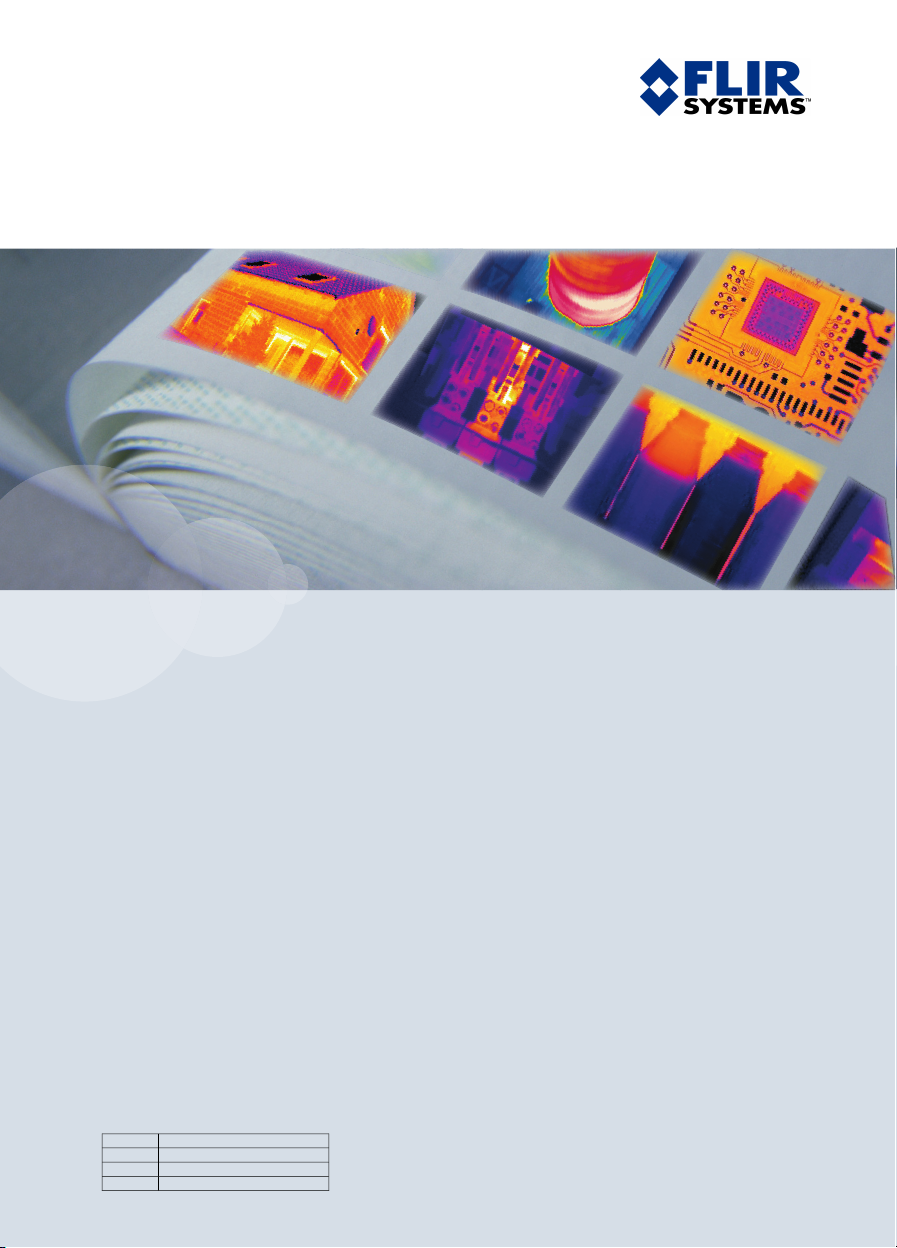
5.1 Front view
Figure
10601703;a2
5
Explanation
Publ. No. 1558299 Rev. a200 – ENGLISH (EN) – February 12, 2007 11
This table gives an explanation to the figure above:
Laser pointer with lens cap1
Focus ring2
Infrared lens3
Lens cap for infrared lens. To prevent losing the lens cap, you can attach
4
it to the tripod mount.
Page 26

5 – Camera parts
(Applies only to models with SD Memory Card:)
5
Slot for SD Memory Card
USB mini-B connector6
NOTE
The laser pointer may not be enabled in all markets.
5
12 Publ. No. 1558299 Rev. a200 – ENGLISH (EN) – February 12, 2007
Page 27
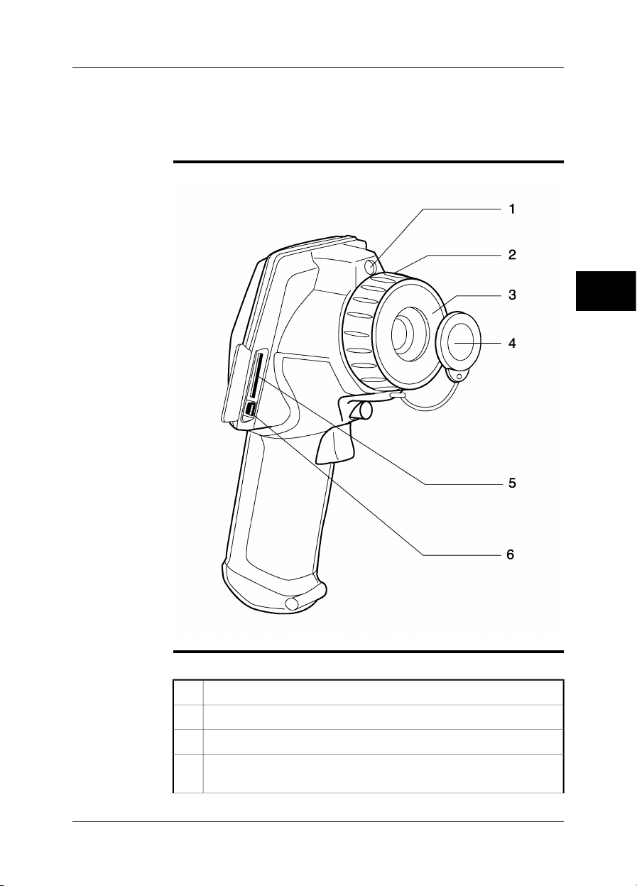
5.2 Side view
5 – Camera parts
Figure
Explanation
10601803;a2
5
This table gives an explanation to the figure above:
Tripod mount 1/4"-201
Top trigger to operate the laser pointer2
Bottom trigger to save an image3
Battery compartment lid4
Rubber lid for power connector5
Locking mechanism for battery compartment lid6
Camera serial number behind rubber lid7
The laser pointer may not be enabled in all markets.
NOTE
■
When you attach the camera to a tripod, use a tripod ball head where the top part
■
does not prevent the operation of the laser trigger.
Publ. No. 1558299 Rev. a200 – ENGLISH (EN) – February 12, 2007 13
Page 28
5 – Camera parts
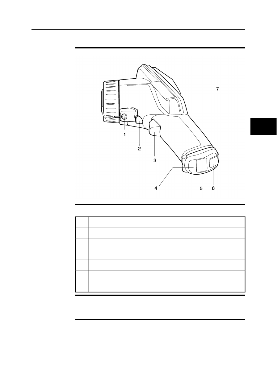
5.3 Keypad
5
Figure
Explanation
10602903;a2
This table gives an explanation to the figure above:
Text that indicates the current function of the left selection button.1
Navigation pad2
Left selection button. This button is context-sensitive.3
Camera/archive button. This button is used to go between camera mode
4
and archive mode.
Text that indicates the current function of the right selection button.5
Right selection button. This button is context-sensitive.6
Power button7
14 Publ. No. 1558299 Rev. a200 – ENGLISH (EN) – February 12, 2007
Page 29

5.4 Controls & functions
5 – Camera parts
General
Explanation
The camera has the following controls:
Four push-buttons
■
One navigation pad
■
Two triggers
■
This table gives an explanation to the figures on page 13 and 14:
FunctionsButton or trigger
Left selection button
The left selection button has the following contextsensitive functions:
Menu
■
Select
■
Options
■
Cancel
■
Delete
■
Push to go between camera mode and archive mode.Camera/archive button
Right selection button
The right selection button has the following contextsensitive functions:
Man/Auto
■
Close
■
Open
■
Overview
■
OK
■
Delete
■
Restore
■
Power button
Push the power button to start the camera.
■
Push and hold the power button for more than 0.5
■
seconds to stop the camera.
Navigation pad
Push up/down or left/right to navigate on menus
■
and in dialog boxes.
Push up/down to change a value.
■
Push left/right to select a menu command in a
■
menu.
Top trigger
Bottom trigger
Pull the top trigger to start the laser pointer.
■
Release the top trigger to stop the laser pointer.
■
Pull and release the bottomtrigger to save oneimage
to the camera memory, or SD Memory Card (depending on camera model).
5
NOTE
Publ. No. 1558299 Rev. a200 – ENGLISH (EN) – February 12, 2007 15
The laser pointer may not be enabled in all markets.
Page 30
5 – Camera parts
5.5 Power indicator
5
General
Figure
Explanation
The camera has two power modes. An indicator shows these modes.
10715803;a3
This table gives an explanation about the indicator:
ExplanationSignal type
The camera is on.The green light is continuous.
The camera is off.The green light is off.
NOTE
If the green light flashes 10 times per second the camera has a hardware problem.
Contact your local sales office for instructions where to send the camera for service.
16 Publ. No. 1558299 Rev. a200 – ENGLISH (EN) – February 12, 2007
Page 31

5.6 Battery condition indicator
5 – Camera parts
General
Figure
Explanation
The battery has a battery condition indicator.
10715703;a3
5
This table gives an explanation about the battery condition indicator:
ExplanationType of signal
The green light flashes two times per
second.
The green light is off.
Publ. No. 1558299 Rev. a200 – ENGLISH (EN) – February 12, 2007 17
The power supply or the stand-alone
battery charger charges the battery.
The battery is fully charged.The green light is continuous.
The camera uses the battery (instead
of the power supply).
Page 32

5 – Camera parts
5.7 Laser pointer
General
Figure
The camera has a laser pointer. When the laser pointer is on, you can see a laser
dot approximately 37 mm (1.5 in.) above the target.
This figure shows the difference in position between the laser pointer and the optical
center of the infrared lens:
10602503;a2
5
WARNING
CAUTION
NOTE
Do not look directly into the laser beam. The laser beam can cause eye irritation.
Protect the laser pointer with the protective cap when you do not operate the laser
pointer.
The laser pointer may not be enabled in all markets.
■
The symbol is displayed on the screen when the laser pointer is on.
■
The distance between the laser beam and the image center changes because of
■
the target distance. Look at the screen to make sure that it displays the correct
target.
18 Publ. No. 1558299 Rev. a200 – ENGLISH (EN) – February 12, 2007
Page 33

5 – Camera parts
Laser warning
label
Laser rules and
regulations
This laser warning label is attached to the camera:
10376403;a2
Wavelength: 635 nm. Max. output power: 1 mW.
This product complies with 21 CFR 1040.10 and 1040.11 except for deviations pursuant to Laser Notice No. 50, dated July 26th, 2001.
5
Publ. No. 1558299 Rev. a200 – ENGLISH (EN) – February 12, 2007 19
Page 34

6 Screen elements
General
Figure
You use screen elements—tools, menus and selections in dialog boxes—to control
the camera program. This section describes the typical set of screen objects.
10715503;a5
6
Explanation
This table gives an explanation to the figure above:
Current function of the left selection button of the keypad1
Laser symbol2
Main menu3
20 Publ. No. 1558299 Rev. a200 – ENGLISH (EN) – February 12, 2007
Page 35

6 – Screen elements
Measured temperature
4
If the symbol > or < precedes the temperature value, the value is above
or below the camera’s temperature range.
The remaining number of images that you can save in the camera
5
■
memory (applies only to models without SD Memory Card)
Free memory on the SD Memory Card in per cent (applies only to
■
models with SD Memory Card)
Indicator that shows battery status and that the camera uses the battery. If
6
the camera uses the power supply, a different indicator is displayed.
Indicator that shows that a USB cable is connected between the camera
7
and a PC
Date and time8
Submenu9
Maximum temperature in the temperature range. In this figure, the minimum
10
temperature is hidden under the main menu.
Indicator that shows if the camera is in auto-adjust mode (A) or manual
11
adjust mode (M)
Current function of the right selection button of the keypad12
Temperature scale13
Tool to change the maximum temperature14
6
Tool to change the maximum and minimum temperature at the same time15
Tool to change the minimum temperature16
Indicator that shows the relative width of the measured temperature span
17
compared to the temperature scale values
Publ. No. 1558299 Rev. a200 – ENGLISH (EN) – February 12, 2007 21
Page 36

6 – Screen elements
6
INTENTIONALLY LEFT BLANK
22 Publ. No. 1558299 Rev. a200 – ENGLISH (EN) – February 12, 2007
Page 37

7 Connecting the cables
7.1 Power cable
General
Figure
SEE ALSO
You connect a power cable to the camera
when you charge the battery;
■
when you use the power supply to operate the camera.
■
10601403;a2
For information about pin configuration, see section 10 – Power connector on
page 60.
7
Publ. No. 1558299 Rev. a200 – ENGLISH (EN) – February 12, 2007 23
Page 38

7 – Connecting the cables
7.2 USB cable
General
Figure
You connect a USB cable to the camera when you move images from the camera
memory to a computer.
10601303;a3
7
SEE ALSO
The camera can stream MPEG4 live video through the USB cable. For more information, see section 8.21 – Viewing streaming MPEG4 live video from the camera on
page 54.
24 Publ. No. 1558299 Rev. a200 – ENGLISH (EN) – February 12, 2007
Page 39

8 Operating the camera
8.1 Installing the battery
NOTE
Procedure
Use a clean and dry cloth to remove any water or moisture on the battery before you
install it.
Follow this procedure to install the battery:
To open the battery compartment lid, push down the locking mechanism.
1
10600803;a1
Push the battery into the battery compartment.
2
10601603;a1
Push the battery compartment lid into position.
3
10601103;a1
8
Publ. No. 1558299 Rev. a200 – ENGLISH (EN) – February 12, 2007 25
Page 40

8 – Operating the camera
8.2 Removing the battery
8
Procedure
Follow this procedure to remove the battery:
To open the battery compartment lid, push down the locking mechanism.
1
10600803;a1
Pull out the battery from the battery compartment.
2
10601003;a1
Push the battery compartment lid into position.
3
10601103;a1
26 Publ. No. 1558299 Rev. a200 – ENGLISH (EN) – February 12, 2007
Page 41

8.3 Charging the battery
8 – Operating the camera
NOTE
General
SEE ALSO
You must charge the battery for four hours before you start the camera the first time.
You must charge the battery when the message Battery voltage is low! is displayed
on the screen.
Do one of these procedures to charge the battery:
Use the combined power supply & battery charger to charge the battery when it
■
is inside the camera.
Use the combined power supply & battery charger to charge the battery when it
■
is outside the camera.
Use the stand-alone battery charger to charge the battery (The stand-alone battery
■
charger is an item that is not included in the standard package.).
For information how to charge the battery, see the following sections:
Section 8.3.1 – Using the combined power supply & battery charger to charge
■
the battery when it is inside the camera on page 28
Section 8.3.2 – Using the combined power supply & battery charger to charge
■
the battery when it is outside the camera on page 29
Section 8.3.3 – Using the stand-alone battery charger to charge the battery on
■
page 30
8
Publ. No. 1558299 Rev. a200 – ENGLISH (EN) – February 12, 2007 27
Page 42

8 – Operating the camera
8.3.1 Using the combined power supply & battery charger to charge the battery when it is inside the camera
8
NOTE
Procedure
NOTE
SEE ALSO
For the clarity of the procedure, the ‘combined power supply & battery charger’ is
called ‘power supply’ below.
Follow this procedure to use the power supply to charge the battery when it is inside
the camera:
To open the battery compartment lid, push down the locking mechanism.1
Push the battery into the battery compartment.2
Push the battery compartment lid into position.3
On the battery compartment lid, open the rubber lid to find the connector
4
on the battery.
Connect the power supply cable plug to the connector on the battery.5
Connect the power supply wall plug to a wall outlet box.6
Disconnect the power supply cable plug when the green light of the battery
7
condition indicator is continuous.
The battery has a battery condition indicator. When the green light is continuous, the
battery is fully charged.
For information about the battery condition indicator, see section 5.6 – Battery
■
condition indicator on page 17.
For information about how to install and remove the battery, see section 8.1 – In-
■
stalling the battery on page 25 and section 8.2 – Removing the battery on page 26.
28 Publ. No. 1558299 Rev. a200 – ENGLISH (EN) – February 12, 2007
Page 43

8 – Operating the camera
8.3.2 Using the combined power supply & battery charger to charge the battery when it is outside the camera
NOTE
Procedure
NOTE
SEE ALSO
For the clarity of the procedure, the ‘combined power supply & battery charger’ is
called ‘power supply’ below.
Follow this procedure to use the powersupply to charge the battery when it is outside
the camera:
Put the battery on a flat surface.1
Connect the power supply cable plug to the connector on the battery.2
Connect the power supply wall plug to a wall outlet box.3
Disconnect the power supply cable plug when the green light of the battery
4
condition indicator is continuous.
The battery has a battery condition indicator. When the green light is continuous, the
battery is fully charged.
For information about the battery condition indicator, see section 5.6 – Battery condition indicator on page 17.
8
Publ. No. 1558299 Rev. a200 – ENGLISH (EN) – February 12, 2007 29
Page 44

8 – Operating the camera
8.3.3 Using the stand-alone battery charger to charge the battery
8
Procedure
NOTE
SEE ALSO
Follow this procedure to use the stand-alone battery charger to charge the battery:
Put the battery in the stand-alone battery charger.1
Connect the power supply cable plug to the connector on the stand-alone
2
battery charger.
Connect the power supply wall plug to a wall outlet box.3
Disconnect the power supply cable plug when the green light of the battery
4
condition indicator is continuous.
The stand-alone battery charger is an item that is not included in the standard
■
package.
The battery has a battery condition indicator. When the green light is continuous,
■
the battery is fully charged.
For information about the battery condition indicator, see section 5.6 – Battery condition indicator on page 17.
30 Publ. No. 1558299 Rev. a200 – ENGLISH (EN) – February 12, 2007
Page 45

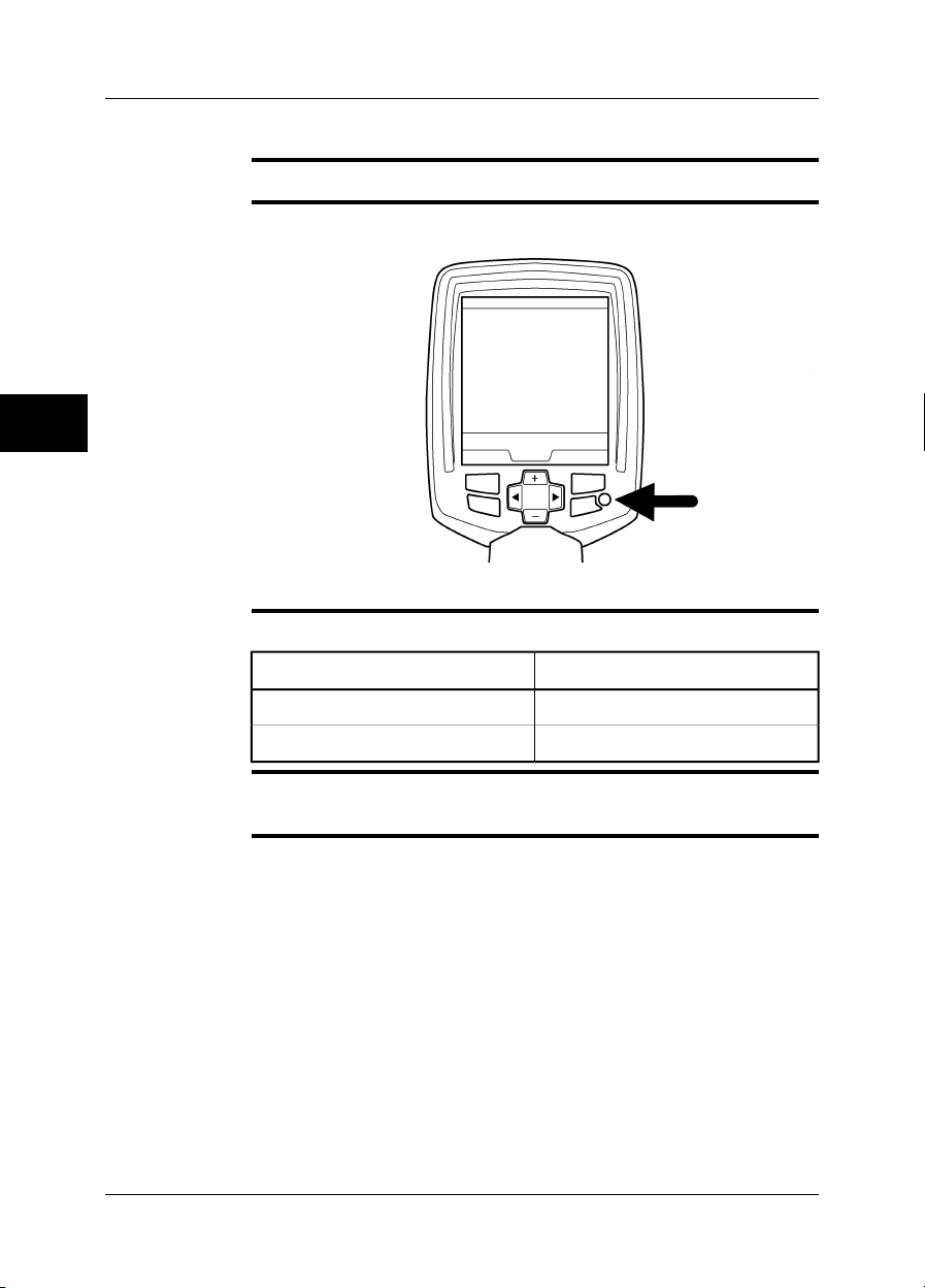
8.4 Starting the camera
8 – Operating the camera
Procedure
Push the power button to start the camera.
8.5 Stopping the camera
Procedure
NOTE
Push and hold the power button for more than 0.5 seconds to stop the camera.
If you do not use the camera, the power goes off after a time period that you can set
in the menu system (See section 8.19 – Changing camera settings on page 51.).
8
Publ. No. 1558299 Rev. a200 – ENGLISH (EN) – February 12, 2007 31
Page 46

8 – Operating the camera
8.6 Adjusting camera focus
Figure
10602803;a1
8
Procedure
Follow this procedure to adjust camera focus:
Hold the camera tightly in your hand.1
Hold the focus ring with the other hand.2
Do one of the following:
3
Turn the focus ring counter-clockwise for far focus.
■
Turn the focus ring clock-wise for near focus.
■
32 Publ. No. 1558299 Rev. a200 – ENGLISH (EN) – February 12, 2007
Page 47

8.7 Operating the laser pointer
8 – Operating the camera
Figure
Procedure
10601203;a3
8
Follow this procedure to operate the laser pointer:
Pull the top trigger to start the laser pointer.1
Release the top trigger to stop the laser pointer.2
NOTE
Publ. No. 1558299 Rev. a200 – ENGLISH (EN) – February 12, 2007 33
The laser pointer may not be enabled in all markets.
Page 48

8 – Operating the camera
8.8 Saving an image
8
General
Naming
convention
Figure
Depending on your camera model, you can save one image or many images to the
camera memory, or on the SD Memory Card.
The naming convention for images is IR_xxxx.jpg, where xxxx is a unique counter.
When you select Restore default the camera resets the counter and assigns the first
highest free file name for the new file.
10601503;a1
Procedure
Pull and release the bottom trigger to save one image to the camera memory, or SD
Memory Card (depending on camera model).
34 Publ. No. 1558299 Rev. a200 – ENGLISH (EN) – February 12, 2007
Page 49

NOTE
8 – Operating the camera
When you save an image to the cameramemory, you save the measured value too.
■
You can save 50 images to the camera memory (applies only to models without
■
SD Memory Card).
You can save 1,000 images to the SD Memory Card (applies only to models with
■
SD Memory Card). More than 1,000 images can be saved on larger SD Memory
Cards, but this will decrease the performance of the camera.
The image file format is compatible with ThermaCAM™ Reporter 8.0 and later
■
(applies only to models with SD Memory Card).
8
Publ. No. 1558299 Rev. a200 – ENGLISH (EN) – February 12, 2007 35
Page 50

8 – Operating the camera
8.9 Auto-adjusting an image
8
General
Procedure
NOTE
For best image brightness and contrast, auto-adjust the camera before you measure
a temperature and save an image.
If the letter M is displayed in the bottom right corner of the screen, push Man/Auto
one time to auto-adjust the image.
If the letter A is displayed in the bottom right corner of the screen, the camera is already auto-adjusted for best image brightness and contrast.
36 Publ. No. 1558299 Rev. a200 – ENGLISH (EN) – February 12, 2007
Page 51

8.10 Adjusting an image manually
8 – Operating the camera
General
Figure
SEE ALSO
If you want to analyze an object with many different temperatures, you can use the
colors of the scale on different parts of the object.
In the left image below a correct analysis of the left cable is difficult to make if you
only auto-adjust the image.You can analyze the left cable more in detailif you increase
or decrease
the maximum temperature level;
■
the minimum temperature level;
■
the maximum and minimum temperature level at the same time.
■
This figure shows two infrared images of cable connection points.
In the image to the left, the image is auto-adjusted. In the right image the maximum
and minimum temperature levels have been changed to temperature levels near the
object. In the temperature scale to the right of each image you can see how the
temperature levels were changed.
10577503;a1
For procedures about how to adjust the image manually, see these sections:
Section 8.10.1 – Increasing or decreasing the maximum temperature level on
■
page 38
Section 8.10.2 – Increasing or decreasing the minimum temperature level on
■
page 39
Section 8.10.3 – Changing both the maximum and minimum temperature level at
■
the same time on page 40
8
Publ. No. 1558299 Rev. a200 – ENGLISH (EN) – February 12, 2007 37
Page 52

8 – Operating the camera
8.10.1 Increasing or decreasing the maximum temperature level
8
Procedure
Follow this procedure to increase or decrease the maximum temperature level:
Do one of the following:
1
If the letter A is displayed in the bottom right corner of the screen, push
■
Man/Auto one time.
If the letter M is displayed in the bottom right corner of the screen, go
■
to the next step below.
2
To select , push the navigation pad left/right.
To change the value, push the navigation pad up/down.3
38 Publ. No. 1558299 Rev. a200 – ENGLISH (EN) – February 12, 2007
Page 53

8 – Operating the camera
8.10.2 Increasing or decreasing the minimum temperature level
Procedure
Follow this procedure to increase or decrease the minimum temperature level:
Do one of the following:
1
If the letter A is displayed in the bottom right corner of the screen, push
■
Man/Auto one time.
If the letter M is displayed in the bottom right corner of the screen, go
■
to the next step below.
2
To select , push the navigation pad left/right.
To change the value, push the navigation pad up/down.3
8
Publ. No. 1558299 Rev. a200 – ENGLISH (EN) – February 12, 2007 39
Page 54

8 – Operating the camera
8.10.3 Changing both the maximum and minimum temperature level at the same time
8
Procedure
Follow this procedure to change both the maximum and minimum temperature at
the same time:
Do one of the following:
1
If the letter A is displayed in the bottom right corner of the screen, push
■
Man/Auto one time.
If the letter M is displayed in the bottom right corner of the screen, go
■
to the next step below.
2
To select , push the navigation pad left/right.
To change the value, push the navigation pad up/down.3
40 Publ. No. 1558299 Rev. a200 – ENGLISH (EN) – February 12, 2007
Page 55

8 – Operating the camera
8.11 Measuring a temperature using a spot meter
General
Procedure
NOTE
You can measure the temperature using a fixed spot meter in the middle of the screen.
Follow this procedure to measure the temperature using a fixed spot meter:
To display the main menu, push Menu.1
2
To select , push the navigation pad up/down.
To enable the menu, push Select.3
To select Temperature, push the navigation pad up/down.4
To save the changes and close the menu, push Close.5
Point the camera at the object you want to measure. The temperature is
6
displayed in the top left corner of the screen.
To display the temperature correctly, the circle in the middle of the spot meter must
be completely filled by the object.
8
Publ. No. 1558299 Rev. a200 – ENGLISH (EN) – February 12, 2007 41
Page 56

8 – Operating the camera
8.12 Measuring a temperature using an area
8
NOTE
General
Procedure
This feature may no be enabled in all camera models.
You can measure the minimum or maximum temperature using a fixed area in the
middle of the screen.
Follow this procedure to measure the minimum or maximum temperature using a
fixed area:
To display the main menu, push Menu.1
2
To select , push the navigation pad up/down.
To enable the menu, push Select.3
Do one of the following:
4
To create an area for which the minimum temperature is indicated in the
■
top left corner of the screen, push the navigation pad up/down to select
Cold and push Select.
To create an area for which the maximum temperature is indicated in
■
the top left corner of the screen, push the navigation pad up/down to
select Hot and push Select.
Point the camera at the object you want to measure.5
42 Publ. No. 1558299 Rev. a200 – ENGLISH (EN) – February 12, 2007
Page 57

8.13 Changing the colors
8 – Operating the camera
General
Procedure
You can change the colors that the camera uses to display different temperatures.
A different set of colors can make it easier to make an analysis of the image.
Follow this procedure to change the color:
To display the main menu, push Menu.1
2
To select , push the navigation pad up/down.
To enable the menu, push Select.3
To select a different color, push the navigation pad up/down.4
To close the menu, push Select.5
8
Publ. No. 1558299 Rev. a200 – ENGLISH (EN) – February 12, 2007 43
Page 58

8 – Operating the camera
8.14 Changing emissivity
General
Example values
Procedure
8
Emissivity is a value that specifies how much radiation an object emits, compared
to the radiation of a theoretical reference object of the same temperature (called a
‘blackbody’).
Except for shiny metals, a value of 0.96 is acceptable for most applications.
Asphalt paving 0.97
0.93Brick, masonry, paint, plastic
0.78Copper, heavily oxidized
0.95Rubber, concrete
0.91Stucco
0.96Tape, electrical black
0.85Wood
Follow this procedure to change emissivity:
To display the main menu, push Menu.1
2
To select , push the navigation pad up/down.
To enable the menu, push Select.3
To select Emissivity, push the navigation pad up/down.4
To enable the Emissivity menu, push Select.5
Do one of the following:
6
Select an emissivity value in the menu.
■
Select Set value to set an arbitrary emissivity value.
■
To close the menu, push Select.7
NOTE
If you set the emissivity to a value lower than 0.5 a warning is displayed on the screen.
This is to remind you that the value is unusually low.
44 Publ. No. 1558299 Rev. a200 – ENGLISH (EN) – February 12, 2007
Page 59

8 – Operating the camera
INTENTIONALLY LEFT BLANK
Publ. No. 1558299 Rev. a200 – ENGLISH (EN) – February 12, 2007 45
8
Page 60

8 – Operating the camera
8.15 Changing the reflected apparent temperature
General
Typical examples
Procedure
8
For very accurate measurements, you must set the reflected apparent temperature.
The reflected apparent temperature compensates for the radiation from the surroundings reflected by the object into the camera.
If emissivity is low and the object temperature differs very much from the reflected
apparent temperature, it is even more important to setthe reflected apparent temperature correctly.
It is, for example, important to set the reflected apparent temperature in the following
situations:
When you use the camera to inspect a hot item under a cold winter sky.
■
When you use the camera to inspect an item in a room where there are hot fur-
■
naces or electrical cabinets at the other end of the room.
Follow this procedure to change the reflected apparent temperature:
Do one of the following:
1
If you already know the reflected apparent temperature, go to step 7
■
below.
If you do not know the reflected apparent temperature, go to step 2 be-
■
low.
Crumble up a large piece of aluminum foil.2
Uncrumble the aluminum foil and attach it to a piece of cardboard of the
3
same size.
Put the piece of cardboard in front of the object you want to measure. Make
4
sure that the side with aluminum foil points to the camera.
Set the emissivity to 1.0 (See section 8.14 – Changing emissivity on
5
page 44.).
Measure the apparent temperature of the aluminium foil and write it down.
6
You will need this value when you set Reflected temp. in step 12 below.
To display the main menu, push Menu.7
8
To select , push the navigation pad up/down.
To enable the menu, push Select.9
To select Reflected temp., push the navigation pad up/down.10
To enable the Reflected temp. box, push Select.11
To select a different value, push the navigation pad up/down.12
To close the menu, push OK.13
46 Publ. No. 1558299 Rev. a200 – ENGLISH (EN) – February 12, 2007
Page 61

8 – Operating the camera
NOTE
SEE ALSO
Do not point the infrared camera (with or without the lens cover) at intensive energy
sources, for example devices that emit laser radiation, or the sun for a long period
of time. This can have an unwanted effect on the accuracy of the camera. It can also
cause damage to the detector in the camera.
For more information about how to measure reflected apparent tempetature, see the
ISO standard DIS 18434-1 and the ASTM standard ASTM E1862-97.
8
Publ. No. 1558299 Rev. a200 – ENGLISH (EN) – February 12, 2007 47
Page 62

8 – Operating the camera
8.16 Opening an image
8
General
Procedure
When you save an image, you store the image in the camera memory, or on the SD
Memory Card, depending on your camera model.
To display the image again, you can open the image from the camera memory, or
SD Memory Card.
Follow this procedure to open an image:
To open the image archive, push the camera/archive button.1
Do one of the following:
2
To find the image you want to open, push the navigation pad left/right.
■
To display thumbnails of all images, push Overview, and follow this
■
procedure:
1 To select the image you want to open, push the navigation pad
up/down or left/right.
2 To open the image, push Open.
To go back to live IR image, push the camera/archive button.3
48 Publ. No. 1558299 Rev. a200 – ENGLISH (EN) – February 12, 2007
Page 63

8.17 Deleting an image
8 – Operating the camera
General
Procedure
You can delete an image from the camera memory.
Follow this procedure to delete an image:
To open the image archive, push the camera/archive button.1
Do one of the following:
2
To delete this image, push Delete.
■
To delete another image, go to Step 3 below.
■
To display thumbnails of all images, push Overview.3
To select the image you want to delete, push the navigation pad up/down
4
or left/right.
Push Options.5
Push Delete.6
Confirm Delete.7
8
Publ. No. 1558299 Rev. a200 – ENGLISH (EN) – February 12, 2007 49
Page 64

8 – Operating the camera
8.18 Deleting all images
8
General
Procedure
You can delete all images from the camera memory.
Follow this procedure to delete all images:
To open the image archive, push the camera/archive button.1
To display thumbnails of all images, push Overview.2
Push Options.3
Push Delete all images.4
Confirm Delete all images.5
50 Publ. No. 1558299 Rev. a200 – ENGLISH (EN) – February 12, 2007
Page 65

8.19 Changing camera settings
8 – Operating the camera
General
Applicability
Procedure
Camera settings have an effect on images and how the camera operates.
The procedure below is applicable to these settings:
Auto off (to set time period after which the camera power goes off)
■
Display intensity (to set intensity of the display)
■
Language (to change language)
■
Unit (to change units)
■
Time format (to change time format)
■
Set time (to set time)
■
Time stamp (to set time-stamping of images)
■
Restore default (to restore factory default values)
■
USB cable (to set USB mode)
■
Follow this procedure to change the camera settings above:
To display the main menu, push Menu.1
2
To select , push the navigation pad up/down.
To enable the Settings menu, push Select.3
To select the setting you want to change, push the navigationpad up/down.4
Use the navigation pad and the following buttons to change the setting:
5
Select
■
Close
■
OK
■
Cancel
■
8
Publ. No. 1558299 Rev. a200 – ENGLISH (EN) – February 12, 2007 51
Page 66

8 – Operating the camera
8.20 Moving images to a PC
8
General
Overview of
methods
Equipment
Method 1
You can move one or many images from the camera to a computer.
You can use two different methods when you move images from the camera to a
computer:
Method 1: Move images when the camera works as a USB disk. With this method
■
you don’t need to install ThermaCAM™ QuickReport on your computer.
Method 2: Move images when the camera is connected to a PC with ThermaCAM™
■
QuickReport. ThermaCAM™ QuickReport contains features for image handling
and creation of PDF reports.
Method 3: Use the SD Memory Card to move images (applies only to models
■
with SD Memory Card).
To move the images from the camera, you need this equipment:
A computer with an IBM-PC, Mac or Linux operating system
■
The program ThermaCAM™ QuickReport (Method 2 only)
■
A USB cable
■
Follow this procedure to move images when the camera works as a USB disk:
To display the main menu, push Menu.1
2
To select , push the navigation pad up/down.
To enable the Settings menu, push Select.3
To select USB cable, push the navigation pad up/down.4
To select Standard, push the navigation pad up/down.5
Click OK.6
Connect the camera and use Windows® Explorer to drag-and-drop images
7
from the camera to the computer.
NOTE
When you select Standard a help text is displayed in the camera. Read the help text
carefully.
52 Publ. No. 1558299 Rev. a200 – ENGLISH (EN) – February 12, 2007
Page 67

8 – Operating the camera
Method 2
NOTE
SEE ALSO
Follow this procedure to move images to a PC with ThermaCAM™ QuickReport:
To display the main menu, push Menu.1
2
To select , push the navigation pad up/down.
To enable the Settings menu, push Select.3
To select USB cable, push the navigation pad up/down.4
To select Network disk. push the navigation pad up/down.5
Click OK.6
Connect the camera to the computeraccording to ThermaCAM™ QuickRe-
7
port User’s manual, Publ. No. –.
See ThermaCAM™ QuickReport User’s manual,Publ. No. –for more instruc-
8
tions.
When you select Network disk a help text is displayed in the camera. Read the help
text carefully.
For information about how to install and use ThermaCAM™ QuickReport, see ThermaCAM™ QuickReport User’s manual, Publ. No. –. FLIR Systems ships this manual
with your camera.
8
Publ. No. 1558299 Rev. a200 – ENGLISH (EN) – February 12, 2007 53
Page 68

8 – Operating the camera
8.21 Viewing streaming MPEG4 live video from the camera
8
General
Procedure
NOTE
The camera can stream MPEG4 live video through the USB cable.
Follow this procedure to view streaming MPEG4 live video from the camera:
Go to http://www.apple.com/quicktime/download/win.html and download
1
the latest version of Apple® QuickTime.
Install the program according to the instructions.2
In the camera, make sure that you select Network disk (USB cable →
3
Network disk).
Connect your camera to your computer.4
Start Apple® QuickTime Player.5
On the File menu, click Open URL.6
In the text box, type rtsp://192.168.0.2.7
Click OK.8
If rtsp://192.168.0.2 does not work in step 7 above, try rtsp://192.168.1.2.
54 Publ. No. 1558299 Rev. a200 – ENGLISH (EN) – February 12, 2007
Page 69

9 Cleaning the camera
9.1 Camera housing, cables & other items
Liquids
Equipment
Procedure
CAUTION
Use one of these liquids:
Warm water
■
A weak detergent solution
■
A soft cloth
Follow this procedure to clean the camera housing, cables & other items:
Soak the cloth in the liquid.1
Twist the cloth to remove the unwanted liquid.2
Clean the part with the cloth.3
Do not use thinner or an equivalent liquid on the camera, the cables and other items.
This can cause damage.
9
Publ. No. 1558299 Rev. a200 – ENGLISH (EN) – February 12, 2007 55
Page 70

9 – Cleaning the camera
9.2 Infrared lens
9
Liquids
Equipment
Procedure
WARNING
CAUTION
Use one of these liquids:
96% ethanol (C2H5OH)
■
A commercial lens cleaning liquid with more than 30% ethanol
■
Cotton wool
Follow this procedure to use a liquid to clean the infrared lens:
Soak the cotton wool in the liquid.1
Twist the cotton wool to remove the unwanted liquid.2
Clean the lens one time only and discard the cotton wool.3
Make sure that you read all applicable MSDS (Material Safety Data Sheets) and
warning labels on containers before you use a liquid. The liquids can be dangerous.
Be careful when you clean the infrared lens. The lens has an anti-reflective coating.
■
Do not clean the infrared lens too much. Thiscan cause damage tothe anti-reflec-
■
tive coating.
56 Publ. No. 1558299 Rev. a200 – ENGLISH (EN) – February 12, 2007
Page 71

10 Technical data
Disclaimer
Imaging
performance
Image
presentation
Object
temperature
ranges
Laser pointer
FLIR Systems reserves the right to discontinue models, parts or accessories, and
other items, or change specifications at any time without prior notice.
Spectral range 7.5–13 μm
Detector type
Thermal sensitivity
Screen 89 mm (3.5 in.) color LCD, 18-bit colors
Object temperature
ranges
Classification Class 2
Type
Focal Plane Array (FPA), uncooled microbolometer
120 × 120 pixels
9 HzImage frequency
± 2.0°C (± 3.6°F) or ± 2% of readingAccuracy
InfraCAM: 0.20℃ (0.36℉)
■
InfraCAM SD: 0.12℃ (0.22℉)
■
Detector image interpolated to 240 × 240 pixelsInterpolation
−10 to +350°C (+14 to +662°F)
Semiconductor AlGaInP diode laser, 1 mW, 635 nm
(red)
10
Publ. No. 1558299 Rev. a200 – ENGLISH (EN) – February 12, 2007 57
Page 72

10 – Technical data
Power system
Battery type Rechargeable Li/Ion battery
2200 mAh, at +20°C to +25°C (+68°F to +77°F)Battery capacity
Battery operating time
Battery charging
Auto off
Approximately 7 hours at +25°C (+77°F) ambient
temperature and typical use
Use the combined power supply & battery charger
■
to charge the battery when it is inside the camera.
Use the combined power supply & battery charger
■
to charge the battery when it is outside the camera.
Use the stand-alone battery charger to charge the
■
battery (The stand-alone battery charger is an item
that is not included in the standard package.).
AC adapter, 90–260 VAC, 50/60 Hz, 12 VDC outAC operation
11–16 VDCVoltage
The camera power goes off after a time period that
the user can set.
10
58 Publ. No. 1558299 Rev. a200 – ENGLISH (EN) – February 12, 2007
Page 73

10 – Technical data
Environmental
data
Physical data
Operating temperature
range
range
Humidity (operating &
storage)
EMC
Total weight 0.55 kg (1.21 lb.), including battery
Size (L × W × H)
Housing material
−15°C to +50°C (+5°F to +122°F)
−40°C to +70°C (−40°F to +158°F)Storage temperature
IEC 68-2-30/24 h 95% relative humidity +25°C to
+40°C (+77°F to +104°F)
EN 61000-6-2:2001 (Immunity)
EN 61000-6-3:2001 (Emission)
FCC 47 CFR Part 15 Class B (Emission)
IP 54 (IEC 60529)Encapsulation
25 g (IEC 60068-2-29)Bump
2 g (IEC 60068-2-6)Vibration
0.12 kg (0.26 lb.)Weight of battery
103.0 × 81.2 × 243.0 mm
(4.1 × 3.2 × 9.6 in.)
Standard, 1/4"-20Tripod mount
Polycarbonate + Acrylonitrile butadiene styrene (PCABS)
TPE Thermoplastic Elastomer PlasticsGrip material
Communication
Publ. No. 1558299 Rev. a200 – ENGLISH (EN) – February 12, 2007 59
USB Image transfer to PC
USB 1.1 Full Speed (12 Mbps)
10
Page 74

10 – Technical data
Power connector
10601903;a1
10
Signal namePin
+12V1
GND2
GND3
60 Publ. No. 1558299 Rev. a200 – ENGLISH (EN) – February 12, 2007
Page 75

10 – Technical data
Field of view &
distance
10602703;a2
Figure 10.1 Relationship between field of view and distance. 1: Distance to target;
2: VFOV = vertical field of view; 3: HFOV = horizontal field of view, 4: IFOV = instan-
taneous field of view (size of one detector element).
This table gives an explanation of field of view at certain distances to targets. D =
distance to target.
10603003;a2
Publ. No. 1558299 Rev. a200 – ENGLISH (EN) – February 12, 2007 61
10
Page 76

10 – Technical data
Optical data
25° × 25°Field of view
10.28 mm (0.40 in.)Focal length
0.125 m (0.409 in.)Close focus limit
1.5F-number
10
62 Publ. No. 1558299 Rev. a200 – ENGLISH (EN) – February 12, 2007
Page 77

11 Dimensional drawings
11.1 Camera
Figure
10602403;a2
Publ. No. 1558299 Rev. a200 – ENGLISH (EN) – February 12, 2007 63
11
Page 78

11 – Dimensional drawings
Figure
10602603;a3
11
64 Publ. No. 1558299 Rev. a200 – ENGLISH (EN) – February 12, 2007
Page 79

11 – Dimensional drawings
Figure
10726103;a1
Publ. No. 1558299 Rev. a200 – ENGLISH (EN) – February 12, 2007 65
11
Page 80

11 – Dimensional drawings
Figure
10726203;a1
NOTE
The tripod mount thread is 1/4"-20.
11
66 Publ. No. 1558299 Rev. a200 – ENGLISH (EN) – February 12, 2007
Page 81

11.2 Battery
11 – Dimensional drawings
Figure
NOTE
10602103;a2
Use a clean and dry cloth to remove any water or moisture on the battery before you
install it.
Publ. No. 1558299 Rev. a200 – ENGLISH (EN) – February 12, 2007 67
11
Page 82

11 – Dimensional drawings
11.3 Stand-alone battery charger
Figure
10602203;a3
The stand-alone battery charger is an item that is not included in the standard
NOTE
11
■
package.
Use a clean and dry cloth to remove any water or moisture on the battery before
■
you put it in the battery charger.
68 Publ. No. 1558299 Rev. a200 – ENGLISH (EN) – February 12, 2007
Page 83

11 – Dimensional drawings
11.4 Stand-alone battery charger with battery
Figure
NOTE
10602303;a3
The stand-alone battery charger is an item that is not included in the standard
■
package.
Use a clean and dry cloth to remove any water or moisture on the battery before
■
you put it in the battery charger.
Publ. No. 1558299 Rev. a200 – ENGLISH (EN) – February 12, 2007 69
11
Page 84

11 – Dimensional drawings
INTENTIONALLY LEFT BLANK
11
70 Publ. No. 1558299 Rev. a200 – ENGLISH (EN) – February 12, 2007
Page 85

12 Introduction to building
thermography
12.1 Important note
All camera functions and features that are described in this section may not be supported by your particular camera configuration.
12.2 Typical field investigations
12.2.1 Guidelines
As will be noted in subsequent sections there are a number of general guidelines the
user should take heed of when carrying out building thermography inspection. This
section gives a summary of these guidelines.
12.2.1.1 General guidelines
■ The emissivity of the majority of building materials fall between 0.85 and 0.95.
Setting the emissivity value in the camera to 0.90 can be regarded as a good
starting point.
■ An infrared inspection alone should never be used as a decision point for further
actions. Always verify suspicions and findings using other methods, such as construction drawings, moisture meters, humidity & temperature datalogging, tracer
gas testing etc.
■ Change level and span to thermally tune the infrared image and reveal more details.
The figure below shows the difference between a thermally untuned and a thermally
tuned infrared image.
10552103;a2
Figure 12.1 LEFT: A thermally untuned infrared image; RIGHT: A thermally tuned infrared image, after
having changed level and span.
Publ. No. 1558299 Rev. a200 – ENGLISH (EN) – February 12, 2007 71
12
Page 86

12 – Introduction to building thermography
12.2.1.2 Guidelines for moisture detection, mold detection & detection of water damages
■ Building defects related to moisture and water damages may only show up when
heat has been applied to the surface, e.g. from the sun.
■ The presence of water changes the thermal conductivity and the thermal mass of
the building material. It may also change the surface temperature of building material due to evaporative cooling. Thermal conductivity is a material’s ability to conduct
heat, while thermal mass is its ability to store heat.
■ Infrared inspection does not directly detect the presence of mold, rather it may be
used to find moisture where mold may develop or has already developed. Mold
requires temperatures between +4°C to +38°C (+40°F to +100°F), nutrients and
moisture to grow. Humidity levels above 50% can provide sufficient moisture to
enable mold to grow.
10556003;a1
Figure 12.2 Microscopic view of mold spore
12.2.1.3 Guidelines for detection of air infiltration & insulation deficiencies
■ For very accurate camera measurements, take measurements of the temperature
12
and enter this value in the camera.
■ It is recommended that there is a difference in pressure between the outside and
the inside of the building structure. This facilitates the analysis of the infrared images
and reveals deficiencies that would not be visible otherwise. Although a negative
pressure of between 10 and 50 Pa is recommended, carrying out the inspection
at a lower negative pressure may be acceptable. To do this, close all windows,
doors and ventilation ducts and then run the kitchen exhaust fan for some time to
reach a negative pressure of 5–10 Pa (applies to residential houses only).
72 Publ. No. 1558299 Rev. a200 – ENGLISH (EN) – February 12, 2007
Page 87

12 – Introduction to building thermography
■ A difference in temperature between the inside and the outside of 10–15°C (18–27°F)
is recommended. Inspections can be carried out at a lower temperature difference,
but will make the analysis of the infrared images somewhat more difficult.
■ Avoid direct sunlight on a part of a building structure—e.g. a façade—that is to be
inspected from the inside. The sunlight will heat the façade which will equalize the
temperature differences on the inside and mask deficiencies in the building structure.
Spring seasons with low nighttime temperatures (±0°C (+32°F)) and high daytime
temperatures (+14°C (+57°F)) are especially risky.
12.2.2 About moisture detection
Moisture in a building structure can originate from several different sources, e.g.:
■ External leaks, such as floods, leaking fire hydrants etc.
■ Internal leaks, such as freshwater piping, waste water piping etc.
■ Condensation, which is humidity in the air falling out as liquid water due to conden-
sation on cold surfaces.
■ Building moisture, which is any moisture in the building material prior to erecting
the building structure.
■ Water remaining from firefighting.
As a non-destructive detection method, using an infrared camera has a number of
advantages over other methods, and a few disadvantages:
DisadvantageAdvantage
The method is quick.
■
The method is a non-intrusivemeans of investi-
■
gation.
The method does not require relocation of the
■
occupants.
The method features an illustrative visual pre-
■
sentation of findings.
The method confirms failure points and mois-
■
ture migration paths.
The method only detects surface temperature
■
differentials and can not see through walls.
The method can not detectsubsurface damage,
■
i.e. mold or structural damage.
12.2.3 Moisture detection (1): Low-slope commercial roofs
12.2.3.1 General information
Low-slope commercial roofing is one of the most common roof types for industrial
building, such as warehouses, industrial plants, machinery shops etc. Its major advantages over a pitched roof is the lower cost in material and building. However, due
to its design where snow and ice will not fall off by itself—as is the case for the majority of pitched roofs—it must be strongly built to support the accumulated weight of
both roof structure and any snow, ice and rain.
Publ. No. 1558299 Rev. a200 – ENGLISH (EN) – February 12, 2007 73
12
Page 88

12 – Introduction to building thermography
Although a basic understanding of the construction of low-slope commercial roofs is
desirable when carrying out a roof thermography inspection, expert knowledge is not
necessary. There is a large number of different design principles for low-slope commercial roofs—both when it comes to material and design—and it would be impossible
for the infrared inspection person to know them all. If additional information about a
certain roof is needed, the architect or contractor of the building can usually supply
the relevant information.
Common causes of roof failure are outlined in the table below (from SPIE Thermosense
Proceedings Vol. 371 (1982), p. 177).
%Cause
47.6Poor workmanship
2.6Roof traffic
16.7Poor design
7.8Trapped moisture
8.0Materials
8.4Age & weathering
Potential leak locations include the following:
■ Flashing
■ Drains
■ Penetrations
■ Seams
■ Blisters
12.2.3.2 Safety precautions
■ Recommend a minimum of two people on a roof, preferably three or more.
■ Inspect the underside of the roof for structural integrity prior to walking on it.
■ Avoid stepping on blisters that are common on built up bitumen and gravel roofs.
■ Have a cell phone or radio available in case of emergency.
12
■ Inform local police and plant security prior to doing nighttime roof survey.
74 Publ. No. 1558299 Rev. a200 – ENGLISH (EN) – February 12, 2007
Page 89

12 – Introduction to building thermography
12.2.3.3 Commented building structures
This section includes a few typical examples of moisture problems on low-slope
commercial roofs.
CommentStructural drawing
10553603;a2
Inadequate sealing of roof membrane around
conduit and ventilation ducts leading to local
leakage around the conduit or duct.
10553703;a2
Publ. No. 1558299 Rev. a200 – ENGLISH (EN) – February 12, 2007 75
Roof membrane inadequately sealed around roof
access hatch.
12
Page 90

12 – Introduction to building thermography
10553803;a2
CommentStructural drawing
Drainage channels located too high and with too
low an inclination. Some water will remain in the
drainage channel after rain, which may lead to local
leakage around the channel.
10553903;a2
Inadequate sealing between roof membrane and
roof outlet leading to local leakage around the roof
outlet.
12.2.3.4 Commented infrared images
12
How do you find wet insulation below the surface of the roof? When the surface itself
is dry, including any gravel or ballast, a sunny day will warm the entire roof. Early in
the evening, if the sky is clear, the roof will begin to cool down by radiation. Because
of its higher thermal capacity the wet insulation will stay warmer longer than the dry
and will be visible in the infrared imager (see photos below). The technique is particularly effective on roofs having absorbent insulation—such as wood fiber, fiberglass,
and perlite—where thermal patterns correlate almost perfectly with moisture.
76 Publ. No. 1558299 Rev. a200 – ENGLISH (EN) – February 12, 2007
Page 91

12 – Introduction to building thermography
Infrared inspections of roofs with nonabsorbent insulations, common in many singleply systems, are more difficult to diagnose because patterns are more diffuse.
This section includes a few typical infrared images of moisture problems on low-slope
commercial roofs:
CommentInfrared image
10554003;a1
Moisture detection on a roof, recorded during the
evening.
Since the building material affected by moisture
has a higher thermal mass,its temperature decreases slower than surrounding areas.
10554103;a1
10554203;a1
Water-damaged roofing components and insulation identified from infrared scan from the underside of the built-up roof on a structural concrete
tee deck.
Affected areas are cooler than the surrounding
sound areas, due to conductive and/or thermal
capacitive effect.
Daytime survey of built-up low-slope commercial
roof.
Affected areas are cooler than the surrounding dry
areas, due to conductiveand/or thermal capacitive
effect.
12
Publ. No. 1558299 Rev. a200 – ENGLISH (EN) – February 12, 2007 77
Page 92

12 – Introduction to building thermography
12.2.4 Moisture detection (2): Commercial & residential façades
12.2.4.1 General information
Thermography has proven to be invaluable in the assessment of moisture infiltration
into commercial and residential façades. Being able to provide a physical illustration
of the moisture migration paths is more conclusive than extrapolating moisture meter
probe locations and more cost-effective than large intrusive test cuts.
12.2.4.2 Commented building structures
This section includes a few typical examples of moisture problems on commercial
and residential façades.
CommentStructural drawing
10554303;a2
Pelting rain penetrates the façade due to badly
executed bed joints. Moisture builds up in the
masonry above the window.
10554403;a2
Pelting rain hits the window at an angle. Most of
the rain runs off the window edge flashing but
some finds its way into the masonry where the
plaster meets the underside of the flashing.
12
78 Publ. No. 1558299 Rev. a200 – ENGLISH (EN) – February 12, 2007
Page 93

10554503;a2
12 – Introduction to building thermography
CommentStructural drawing
Rain hits the façade at an angle and penetrates
the plaster through cracks. The water then follows
the inside of the plaster and leads to frost erosion.
10554603;a2
Rain splashes on the façade and penetrates the
plaster and masonry by absorption, whicheventually leads to frost erosion.
12
Publ. No. 1558299 Rev. a200 – ENGLISH (EN) – February 12, 2007 79
Page 94

12 – Introduction to building thermography
12.2.4.3 Commented infrared images
This section includes a few typical infrared images of moisture problems on commercial
& residential façades.
CommentInfrared image
10554703;a1
Improperly terminated and sealed stone veneer to
window frame and missing flashings has resulted
in moisture infiltration into the wall cavity and interior living space.
10554803;a1
Moisture migration into drywall from capillary drive
and interior finish components from inadequate
clearance and slope of grade from vinyl siding
façade on an apartment complex.
12.2.5 Moisture detection (3): Decks & balconies
12.2.5.1 General information
Although there are differences in design, materials and construction, decks—plaza
12
decks, courtyard decks etc—suffer from the same moisture and leaking problems as
low-slope commercial roofs. Improper flashing, inadequately sealed membranes,
and insufficient drainage may lead to substantial damage in the building structures
below.
Balconies, although smaller in size, require the same care in design, choice of material, and workmanship as any other building structure. Since balconies are usually
supported on one side only, moisture leading to corrosion of struts and concrete reinforcement can cause problems and lead to hazardous situations.
80 Publ. No. 1558299 Rev. a200 – ENGLISH (EN) – February 12, 2007
Page 95

12 – Introduction to building thermography
12.2.5.2 Commented building structures
This section includes a few typical examples of moisture problems on decks and
balconies.
CommentStructural drawing
10555203;a2
Improper sealing of paving and membrane to roof
outlet, leading to leakage during rain.
10555103;a2
Publ. No. 1558299 Rev. a200 – ENGLISH (EN) – February 12, 2007 81
No flashing at deck-to-wall connection, leading to
rain penetrating the concrete and insulation.
12
Page 96

12 – Introduction to building thermography
10555003;a2
CommentStructural drawing
Water has penetrated the concrete due to inadequately sized drop apron and has led to concrete
disintegration and corrosion of reinforcement.
SECURITY RISK!
12
10554903;a2
Water has penetrated the plaster and underlying
masonry at the pointwhere the handrailis fastened
to the wall.
SECURITY RISK!
82 Publ. No. 1558299 Rev. a200 – ENGLISH (EN) – February 12, 2007
Page 97

12 – Introduction to building thermography
12.2.5.3 Commented infrared images
This section includes a few typical infrared images of moisture problems on decks
and balconies.
CommentInfrared image
10555303;a1
Improper flashing at balcony-to-wall connections
and missing perimeter drainage system resulted
in moisture intrusion into the wood framingsupport
structure of the exterior walkway balcony of a loft
complex.
10555403;a1
A missing composite drainage plane or medium
on a below-grade parking garage plaza deck
structure resulted in standing water between the
structural concrete deck and the plaza wearing
surface.
12.2.6 Moisture detection (4): Plumbing breaks & leaks
12.2.6.1 General information
Water from plumbing leaks can often lead to severe damage on a building structure.
Small leaks may be difficult to detect, but can—over the years—penetrate structural
walls and foundations to a degree where the building structure is beyond repair.
Using building thermography at an early stage when plumbing breaks and leaks are
suspected can lead to substantial savings on material and labor.
12
Publ. No. 1558299 Rev. a200 – ENGLISH (EN) – February 12, 2007 83
Page 98

12 – Introduction to building thermography
12.2.6.2 Commented infrared images
This section includes a few typical infrared images of plumbing breaks & leaks.
CommentInfrared image
10555503;a1
Moisture migration tracking along steel joist channels inside ceiling of a single family home where
a plumbing line had ruptured.
12
10555603;a1
Water from plumbing leak was found to have migrated farther than originally anticipated by the
contractor during remediation techniques of cutting
back carpet and installing dehumidifiers.
84 Publ. No. 1558299 Rev. a200 – ENGLISH (EN) – February 12, 2007
Page 99

10555703;a1
12 – Introduction to building thermography
CommentInfrared image
The infrared image of this vinyl-sided 3-floor
apartment house clearly shows the path of a serious leak from a washing machine on the third floor,
which is completely hidden within the wall.
10555803;a1
Water leak due to improper sealing between floor
drain and tiles.
Publ. No. 1558299 Rev. a200 – ENGLISH (EN) – February 12, 2007 85
12
Page 100

12 – Introduction to building thermography
12.2.7 Air infiltration
12.2.7.1 General information
Due to the wind pressure on a building, temperature differences between the inside
and the outside of the building, and the fact that most buildings use exhaust air terminal
devices to extract used air from the building, a negative pressure of 2–5 Pa can be
expected. When this negative pressure leads to cold air entering the building structure
due to deficiencies in building insulation and/or building sealing, we have what is
called air infiltration. Air infiltration can be expected at joints and seams in the building
structure.
Due to the fact that air infiltration creates an air flow of cool air into e.g. a room, it can
lead to substantial deterioration of the indoor climate. Air flows as small as 0.15 m/s
(0.49 ft./s) are usually noticed by inhabitants, although these air flows may be difficult
to detect using ordinary measurement devices.
On an infrared image air infiltration can be identified by its typical ray pattern, which
emanates from the point of exit in the building structure—e.g. from behind a skirting
strip. Furthermore, areas of air infiltration typically have a lower detected temperature
than areas where there is only an insulation deficiency. This is due to the chill factor
of the air flow.
12.2.7.2 Commented building structures
This section includes a few typical examples of details of building structures where
air infiltration may occur.
CommentStructural drawing
10552503;a2
Insulation deficiencies at the eaves of a brickwall
house due to improperly installed fiberglass insulation batts.
The air infiltration enters the room from behind the
cornice.
12
86 Publ. No. 1558299 Rev. a200 – ENGLISH (EN) – February 12, 2007
 Loading...