

Page 1
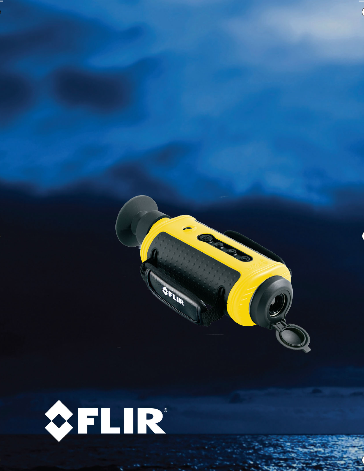
HM-Series
Thermal Night Vision Camera
Operator’s Manual
Document Number: 432-0004-00-10
Revision: 100
January 2010
Page 2

— HM-Series Operator’s Manual
© 2010 FLIR Commercial Systems, Inc. All rights reserved worldwide. No
parts of this manual, in whole or in part, may be copied, photocopied,
translated, or transmitted to any electronic medium or machine readable
form without the prior written permission of FLIR Commercial Systems, Inc.
Names and marks appearing on the products herein are either registered
trademarks or trademarks of FLIR Commercial Systems, Inc. and/or its
subsidiaries. All other trademarks, trade names, or company names
referenced herein are used for identification only and are the property of their
respective owners.
This product is protected by patents, design patents, patents pending, or
design patents pending.
If you have questions that are not covered in this manual, or need service,
contact FLIR Commercial Systems, Inc. customer support at 805.964.9797
for additional information prior to returning a camera.
This documentation is subject to change without notice.
This equipment must be disposed of as electronic waste.
Contact your nearest FLIR Commercial Systems, Inc.
representative for instructions on how to return the product to
FLIR for proper disposal.
This document is controlled to FLIR Technology Level EAR 1. The information
contained in this document is proprietary and/or restricted and pertains to a
dual use product controlled for export by the Export Administration
Regulations (EAR). This document and data disclosed herein or herewith is not
to be reproduced, used, or disclosed in whole or in part to anyone without the
written permission of FLIR Systems, Inc. Diversion contrary to US law is
prohibited. US Department of Commerce authorization is not required prior to
export or transfer to foreign persons, parties, or uses otherwise prohibited.
70 Castilian Drive
Goleta, CA 93117
Phone: 888.747.FLIR (888.747.3547)
International: +1.805.964.9797
www.flir.com
ii January 2010
Page 3

HM-Series Operator’s Manual —
Table of Contents
Introduction. . . . . . . . . . . . . . . . . . . . . . . . . . . . . . . . . . . . . . . . . . . . . . . . . . . 1
HM-Series Camera Features. . . . . . . . . . . . . . . . . . . . . . . . . . . . . . . . 2
Cautions . . . . . . . . . . . . . . . . . . . . . . . . . . . . . . . . . . . . . . . . . . . . . . . . . . 3
Getting Started . . . . . . . . . . . . . . . . . . . . . . . . . . . . . . . . . . . . . . . . . . . . . . . 5
Shipping Kits . . . . . . . . . . . . . . . . . . . . . . . . . . . . . . . . . . . . . . . . . . . . . . 6
Options and Accessories . . . . . . . . . . . . . . . . . . . . . . . . . . . . . . . . . . . 7
Operating Your HM-Series Camera . . . . . . . . . . . . . . . . . . . . . . . . . . . 11
Camera Features and Controls . . . . . . . . . . . . . . . . . . . . . . . . . . . 11
Installing the Batteries and SD Card . . . . . . . . . . . . . . . . . . . . . . . 12
Charging the Camera . . . . . . . . . . . . . . . . . . . . . . . . . . . . . . . . . . . . 13
HM-Series Power Management . . . . . . . . . . . . . . . . . . . . . . . . . . . 14
Buttons and Controls . . . . . . . . . . . . . . . . . . . . . . . . . . . . . . . . . . . . 16
Batteries. . . . . . . . . . . . . . . . . . . . . . . . . . . . . . . . . . . . . . . . . . . . . . . . 20
SD Card Door . . . . . . . . . . . . . . . . . . . . . . . . . . . . . . . . . . . . . . . . . . . 21
Auto-Standby Operation . . . . . . . . . . . . . . . . . . . . . . . . . . . . . . . . . . 23
The Hot Shoe . . . . . . . . . . . . . . . . . . . . . . . . . . . . . . . . . . . . . . . . . . . . 24
Installing the Shuttered Eyepiece . . . . . . . . . . . . . . . . . . . . . . . . . . 25
Bayonet Lens Mounting System . . . . . . . . . . . . . . . . . . . . . . . . . . . 26
2× Extender . . . . . . . . . . . . . . . . . . . . . . . . . . . . . . . . . . . . . . . . . . . . . 27
Installing Software Upgrades. . . . . . . . . . . . . . . . . . . . . . . . . . . . . . 28
Technical Data . . . . . . . . . . . . . . . . . . . . . . . . . . . . . . . . . . . . . . . . . . . . . . 29
HM-Series Camera Model Features . . . . . . . . . . . . . . . . . . . . . . . 29
Power . . . . . . . . . . . . . . . . . . . . . . . . . . . . . . . . . . . . . . . . . . . . . . . . . . 30
Environmental . . . . . . . . . . . . . . . . . . . . . . . . . . . . . . . . . . . . . . . . . . . 30
Physical . . . . . . . . . . . . . . . . . . . . . . . . . . . . . . . . . . . . . . . . . . . . . . . . . 30
Lens Choice . . . . . . . . . . . . . . . . . . . . . . . . . . . . . . . . . . . . . . . . . . . . . 30
Storage File Formats . . . . . . . . . . . . . . . . . . . . . . . . . . . . . . . . . . . . . 31
Range Detection . . . . . . . . . . . . . . . . . . . . . . . . . . . . . . . . . . . . . . . . . 31
432-0004-00-10, Revision 100 iii
Page 4

— HM-Series Operator’s Manual
iv January 2010
Page 5
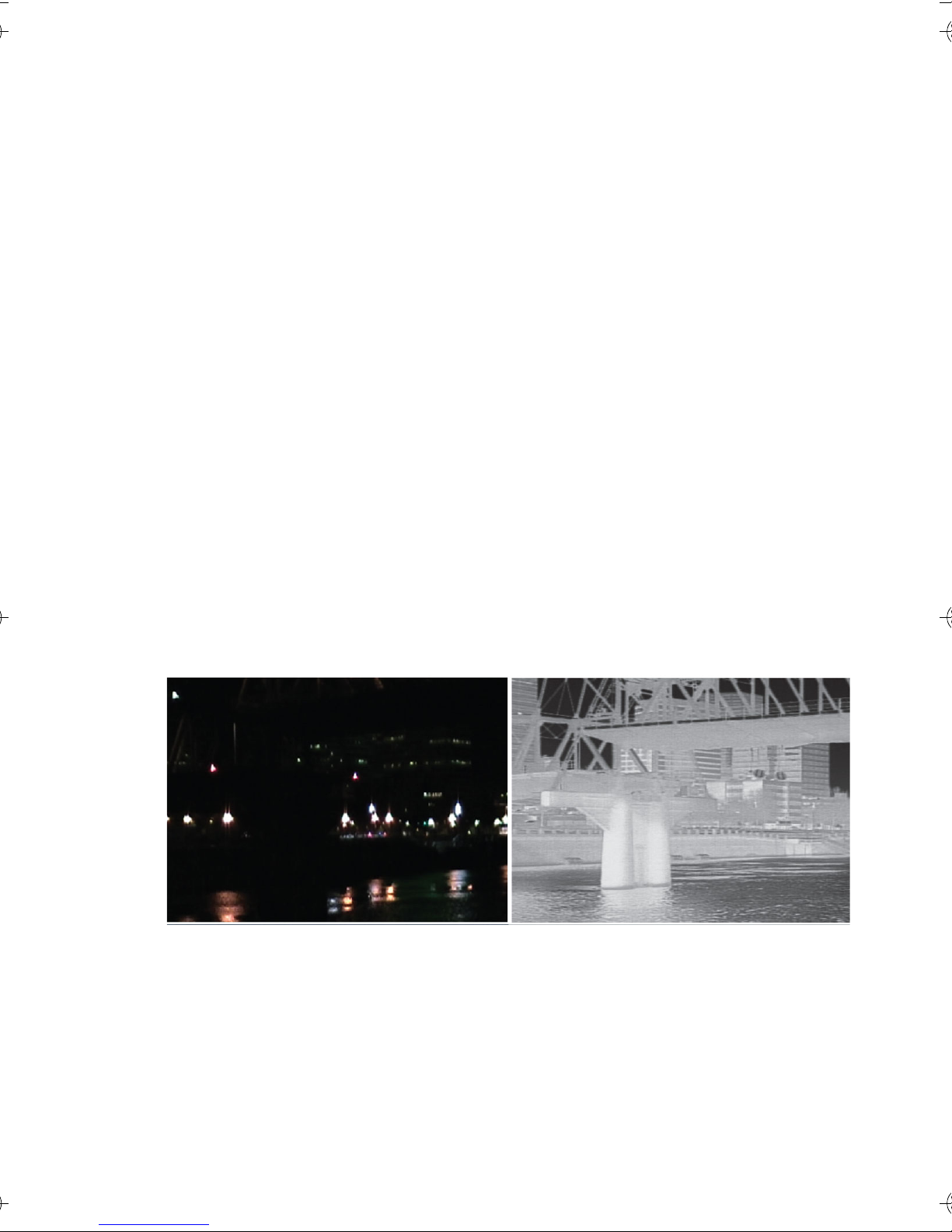
1Introduction
The HM-Series handheld thermal imaging camera gives every
mariner the power to see at night like never before.
The HM-Series camera gives you the power to see more—and to see
farther—than every other night vision technology around:
• When you have the HM-Series camera on deck, at night in dark
anchorages you will be able to see your surroundings, even when
it is cloudy and there is no moonlight or starlight.
• See clearly in total darkness—unlike other night vision systems,
HM-Series cameras require no light at all
• See logs, rocks, land, and other hazards that radar can miss
• Boat with confidence at night knowing that you can see harbor
entrances and navigation channels in total darkness
• See with FLIR’s award-winning maritime thermal night vision
technology in the palm of your hand
Your Vision
432-0004-00-10, Revision 100 1
Image with HM-Series Camera
Page 6
1—Introduction HM-Series Operator’s Manual
1–1 HM-Series Camera Features
• Rugged design—Built to withstand the demands of maritime use.
It is fully submersible (IP67).
• 240×180 or 320×240 microbolometer sensor for excellent
image quality and clarity
• Hot Shoe—Provides convenient power input and video output.
• Choose the 19 mm lens with 24° field of view or include a
removable 2× optical extender.
• Two-sided Hand Strap—Accommodates both left-handed and
right-handed users.
• Software upgrades using an SD card.
• SD Card Slot—Allows for storing captured still images and video
(HM-324 XP+
only) on the removable SD card.
1
• USB 2.0 Connection—Rapid transfer of files from the camera to
a PC.
1
• Four rechargeable AA NiMH batteries—Provides up to 5 hours of
camera operation on a single charge.
1. Available only with the HM-224 Pro or HM-324 XP+ models.
2 January 2010
Page 7

HM-Series Operator’s Manual 1—Introduction
1–2 Cautions
Do not disassemble the camera enclosure. Disassembly can
cause permanent damage and will void the warranty.
Keep the compartment covers closed to avoid exposing the
cameras electronics to water or debris.
Do not point the camera directly at extremely high-intensity
radiation sources, such as the sun, lasers, arc welders, etc.
Only use the auxiliary power adapters provided with your
HM-Series camera (car adapter or AC adapter). Connecting the
camera to an improper power source may damage the camera
and void your warranty.
Be careful not to leave fingerprints on the camera’s infrared
optics.
Caution!
The camera window has an anti-reflective coating and should only
be cleaned with low pressure fresh water and a lens cloth.
Improper care of the camera window can cause damage to the
anti-reflective coating, degrade the camera’s performance, and
void the camera warranty.
432-0004-00-10, Revision 100 3
Page 8

1—Introduction HM-Series Operator’s Manual
4 January 2010
Page 9

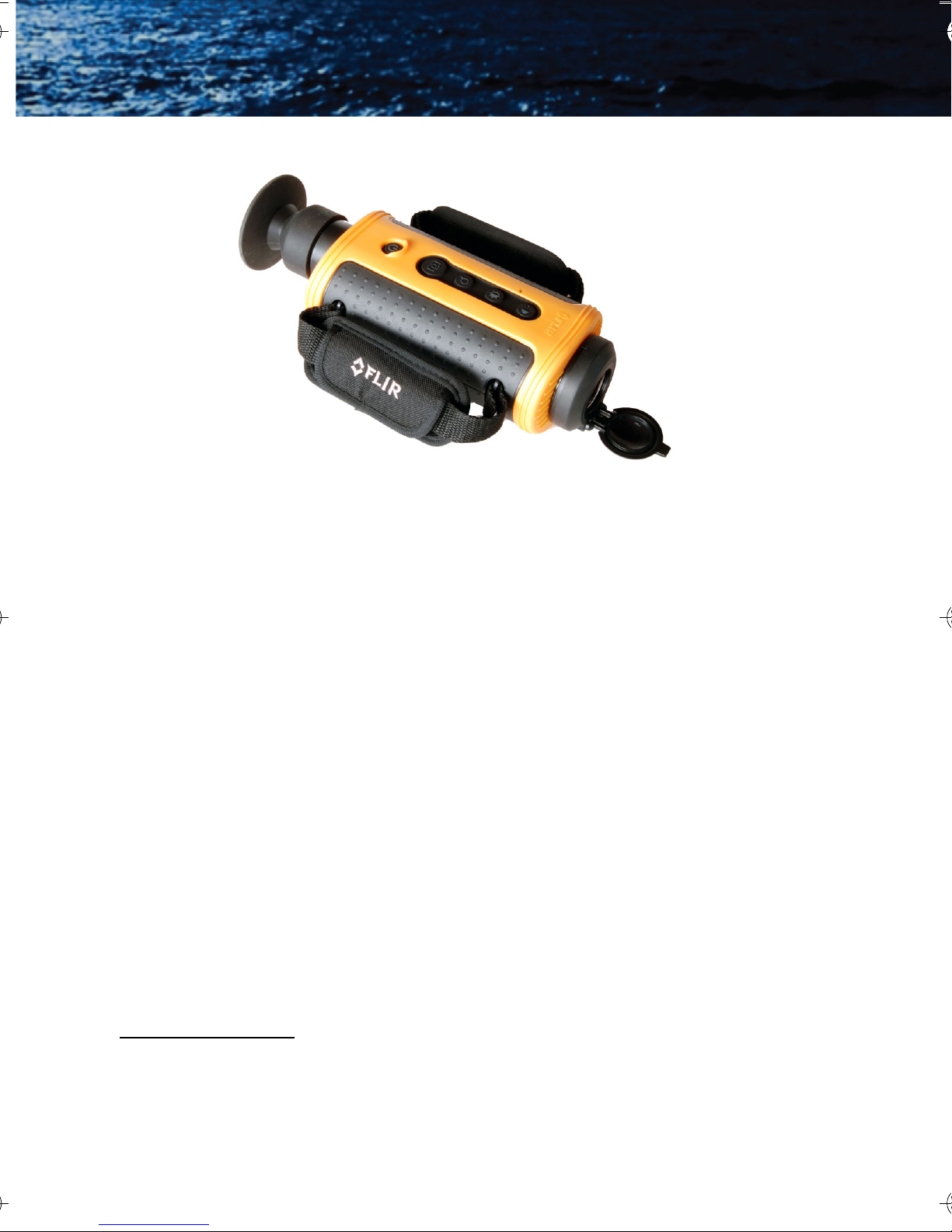
2 Getting Started
The HM-Series cameras shown below are available with the features,
options, and accessories described in this manual.
19 mm Lens Configuration
19 mm Lens with 2× Extender
Focus Ring
432-0004-00-10, Revision 100 5
Page 10
2—Getting Started HM-Series Operator’s Manual
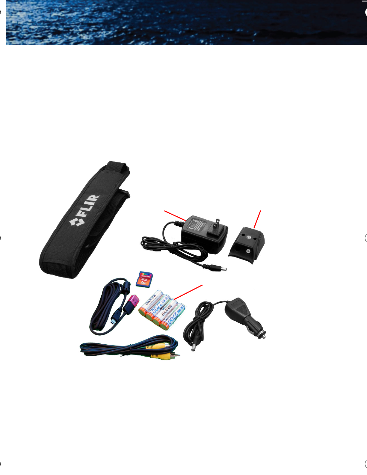
2–1 Shipping Kits
Refer to the packing list enclosed with your camera shipment to
determine the actual contents of your camera package.
• HM-224 and HM-324 XP Cameras
• HM-224 Pro and HM-324 XP+ Cameras
• In addition to the camera, Quick Start card, and Documentation/
Training CD or DVD; the following items are included in the
camera package:
Neck Lanyard
USB Cable
Video Output Cable
AC Power Adaptor
1-Gb SD Card
Hot Shoe
AA Rechargeable Batteries
Car Adaptor
6 January 2010
Page 11
HM-Series Operator’s Manual 2—Getting Started
2–2 Options and Accessories
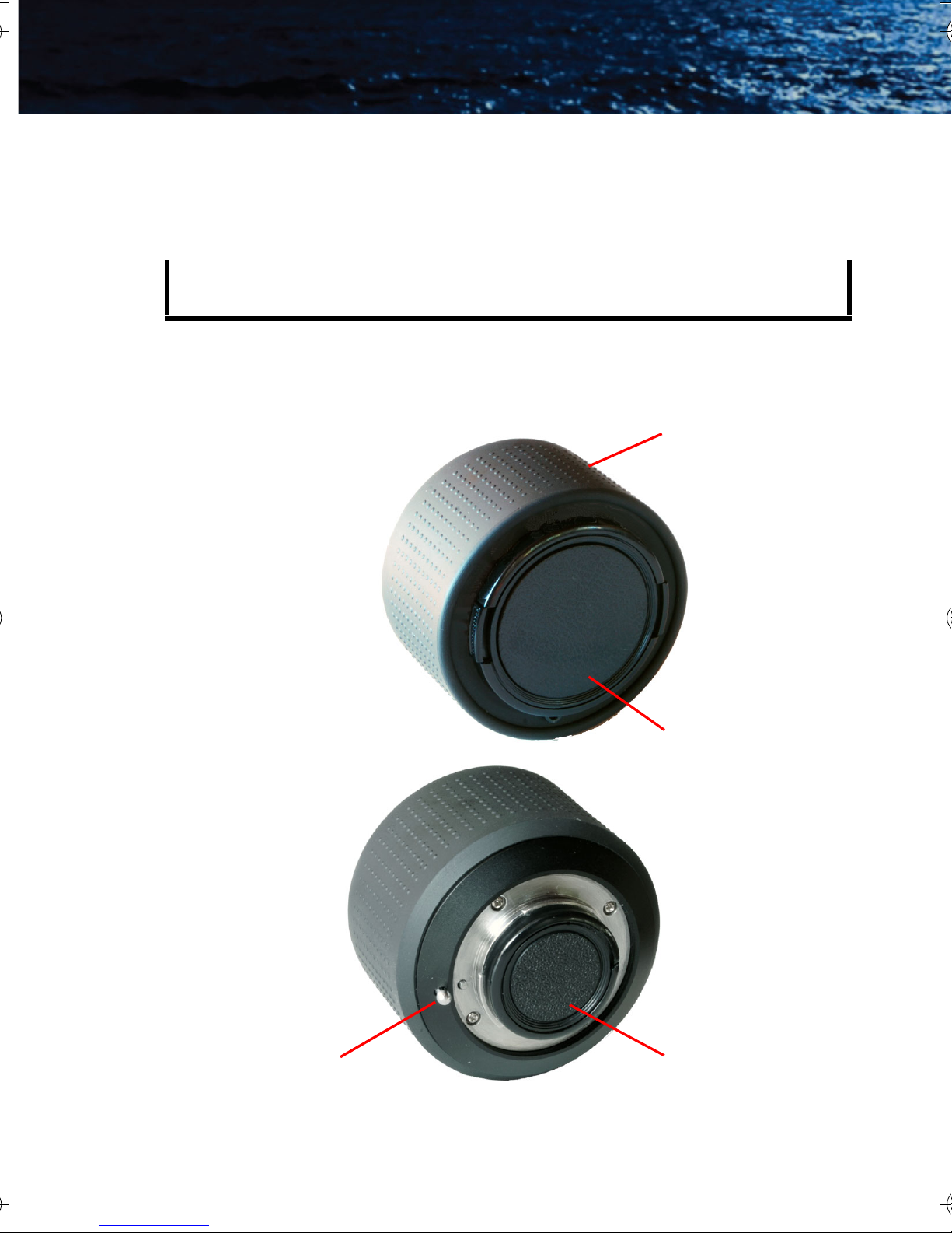
2× Optical Extender for 19 mm lens:
Note
The 2× Optical Extender is not waterproof and should not be used
in wet environments.
The attachable 2× Optical Extender lens doubles the range of
performance when needed, without sacrificing the situational
awareness benefits of the wide field of view lens.
Manual Focus Ring
Front Lens Cover
Lens Release Lever
432-0004-00-10, Revision 100 7
Rear Lens Cover
Page 12
2—Getting Started HM-Series Operator’s Manual
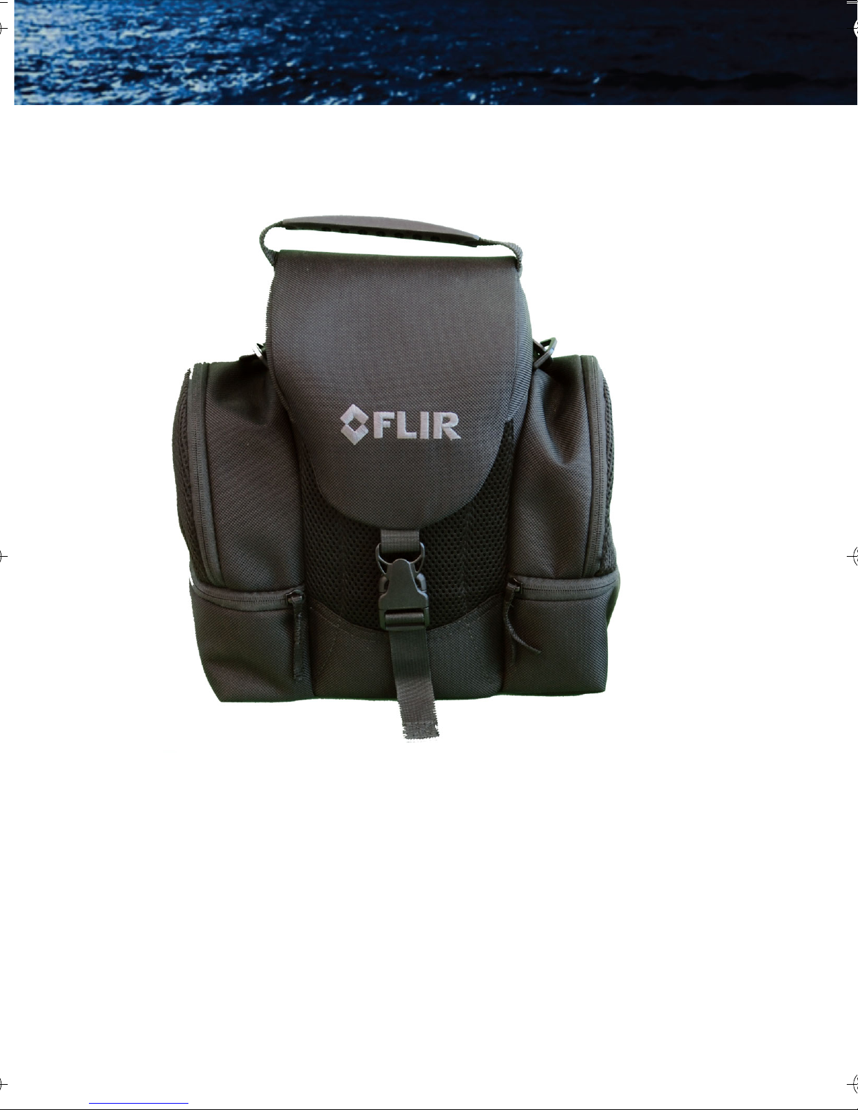
Camera Case
Protection for your camera and all accessories.
8 January 2010
Page 13

HM-Series Operator’s Manual 2—Getting Started
Hardshell Storage Case
Protection for your camera and all accessories.
432-0004-00-10, Revision 100 9
Page 14

2—Getting Started HM-Series Operator’s Manual
10 January 2010
Page 15

3 Operating Your HM-Series Camera
3–1 Camera Features and Controls
Brightness
Lens cap
Black hot
Capture
Adjustable
diopter ±2
Power2× zoomWhite hot/Display
Eyepiece
SD Card
door
Hot Shoe
power contacts
Hot Shoe/
Tripod mount
Battery
cover
432-0004-00-10, Revision 100 11
Page 16

3—Operating Your HM-Series Camera HM-Series Operator’s Manual
3–2 Installing the Batteries and SD Card
The batteries must be installed and charged before using your
camera. If an SD card is included with your camera package, you can
also install it at this time.
1. To help later when removing
the battery cover, remove
the small SD card door. No
tools are required.
2. If included with your camera
package, install the SD card.
–
+
–
+
+
–
+
–
Battery
cover
Grasp SD card door edges and pull
3. Loosen the four captive screws
securing the battery cover.
4. Remove the battery cover by
grasping the front edge exposed
when the card door was removed.
5. Install the batteries as shown.
6. Snap the SD card door back into
place, ensuring that the rubber
lanyard retracts into the camera.
7. Re-install the battery cover—it only fits one way.
8. Tighten the four screws.
If you have installed rechargable batteries, they must be charged
before using the camera. Regular AA batteries will provide about one
and a half hours of camera use.
12 January 2010
Page 17

HM-Series Operator’s Manual 3—Operating Your HM-Series Camera
3–3 Charging the Camera
The batteries in the camera must be fully charged prior to use. If not
fully charged or if the recommended batteries are not installed, the
battery status indicator may not accurately reflect the remaining
battery life. Only use the auxiliary power adapters provided with your
HM-Series camera (car adapter or AC adapter).
1. Connect the Hot Shoe to your camera.
2. Rotate the attachment wheel in
the clockwise direction until tight.
3. Plug the power adapter provided
with the camera into its power
source and also into the Hot Shoe.
4. Ensure that the plug is fully
Plug from power adapter
seated in the Hot Shoe.
When charging correctly, the
charging indicator will be lit
Charging
indicator
yellow and will blink green for one
second within about 35 seconds.
The charging indicator will
continue to blink at decreasing
intervals until the batteries are
fully charged.
Solid
green
When fully charged, the charging
indicator will be lit solid green.
The initial charge time is
approximately 4 hours.
Note
The charging indicator will be lit solid green when the Hot Shoe is
not connected to the camera or the recommended batteries are
not installed. Ensure the batteries are charging by verifying the
green blink described above.
432-0004-00-10, Revision 100 13
Page 18

3—Operating Your HM-Series Camera HM-Series Operator’s Manual
3–4 HM-Series Power Management
Your HM-Series camera is equipped with a power management
system that provides up to five hours of continuous operation and up
to five days of standby time between battery charges. To make the
best use of the camera and to assure it is always ready when you need
it, it is important to understand the basic power states of the camera.
The HM-Series camera is designed to operate much like your cell
phone:
• It is rarely turned off unless you do not plan to use it for a few
days or more.
• When near a power source (AC power or a car cigarette lighter)
or when not in use, you keep it on a charger.
• When you turn it on from all the way off, it takes about 90
seconds to become operational.
• In Standby, it is always ready to go. Press the Power button and it
is on in about two seconds.
• It will automatically put itself in Standby to conserve the battery.
A red state LED located next to the display indicates the current power
state and can only be seen when the shuttered eyepiece is opened (for
example, when the camera is held up to the eye) or when the eyepiece
is removed as shown in the photograph below.
State LEDDisplay screen
14 January 2010
Page 19

HM-Series Operator’s Manual 3—Operating Your HM-Series Camera
Power States
• Three power states: Off, On, and Standby
• The initial power-on Bootup process between the Off state and
the On state takes about 90 seconds (fast flashing red state
LED). During the Bootup process, pressing the Power button
again will turn the camera off. After the camera finishes its
power-on Bootup process, it is in the On state (state LED is off).
After the camera is On, pressing the Power button will toggle the
camera between On and Standby (state LED is flashing slowly).
• When battery powered, if Auto-Standby is enabled (see “AutoStandby Operation” on page 23), the camera goes to Standby
after three minutes if no buttons are pushed. A warning is shown
in the display.
• From the Standby state, the camera comes back on within about
two seconds when the Power button is pushed.
• The Auto-Standby function is disabled if the camera is powered
with external power.
During most use scenarios you will change between Standby and On.
When the camera will not be used for extended periods, you might
consider putting the camera into the OFF state.
Camera
State
Off The display and the state LED are off
Power-on Bootup—Color bars on the display and the state
LED is flashing quickly
On
There is a thermal image on the display and the state LED
is off
Standby The display is off and the state LED is flashing slowly
How do you know?
432-0004-00-10, Revision 100 15
Page 20
3—Operating Your HM-Series Camera HM-Series Operator’s Manual
3–5 Buttons and Controls
Power Button
Changing between the Off, On, and Standby power states is
controlled by the Power button. The table below describes
how the camera moves between states.
From
State
Off On Press the Power button for 1 second. (This will put the
On Standby Momentarily press the Power button
Standby On Momentarily press the Power button
On Off Press and hold the Power button for 8 seconds
Standby Off Press and hold the Power button for 8 seconds
To
Method
State
camera in power-on bootup for about 90 seconds
before going to On.)
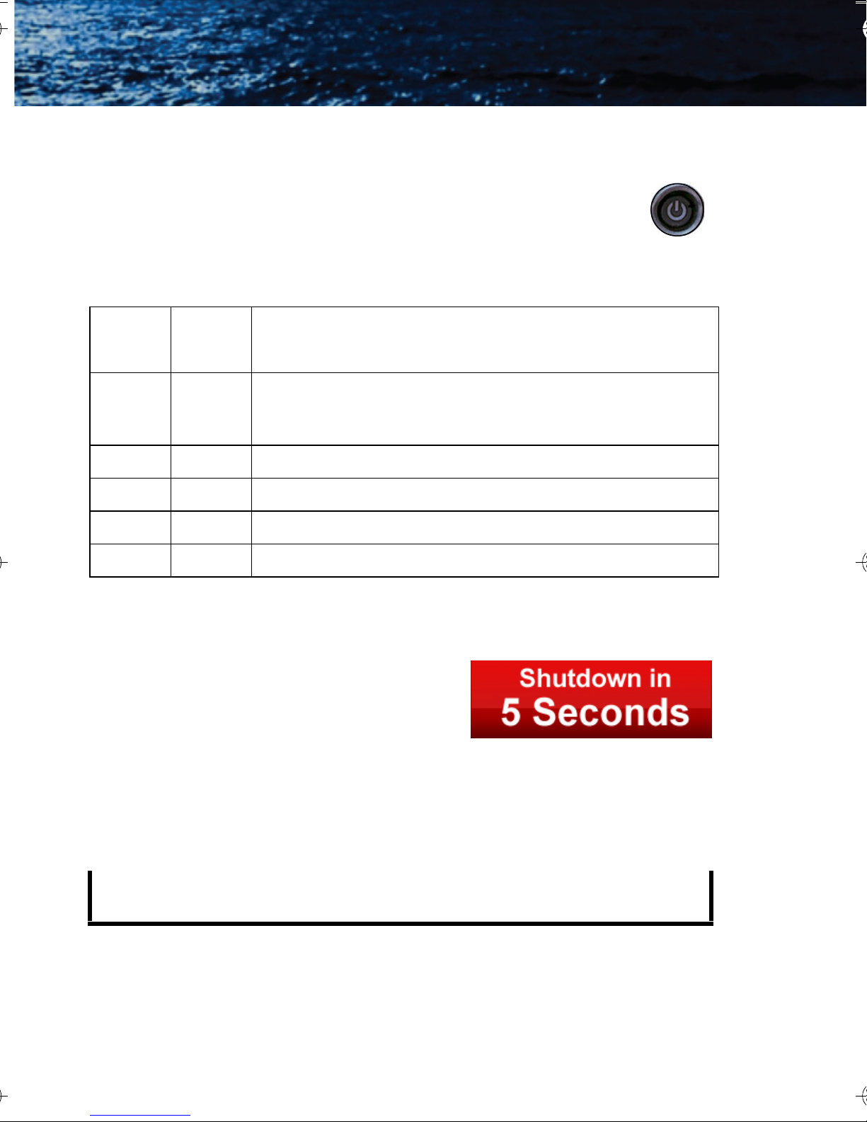
To shut off the camera completely press and hold the Power button
for eight seconds.
After holding the Power button for three
seconds the following message will be
shown in the display and the camera will
enter the Off state if the countdown
finishes.
Release the Power button at any time during this countdown to
terminate Shutdown and resume normal operation.
Note
If the camera is in the Standby state and the Power button is held
down for eight seconds, the camera will shutdown without warning.
16 January 2010
Page 21
HM-Series Operator’s Manual 3—Operating Your HM-Series Camera
Capture Button–HM-224 Pro and HM-324 XP+
models only
Use this button to capture snapshots (in JPEG format) or
video clips (HM-324 XP+ only). The files are stored on the SD card.
• Momentarily pressing the button captures a single snapshot.
• Pressing and holding the button will cause the camera to save a
video clip file. The camera continues storing video until the
capture button is released. The file is then written to the SD card.
Twenty-five seconds of video requires about one megabyte (MB) of
storage on the SD card. The image and video files must be transferred
to a computer for viewing.
Note
The images must be transferred to a computer via the USB cable,
or the SD card can be temporarily removed from the camera and
inserted in a card reader.
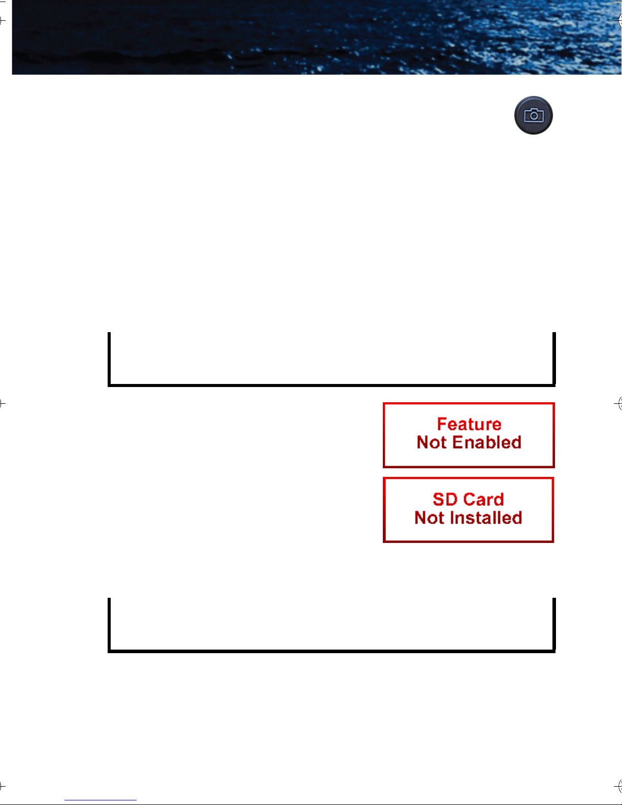
• If the camera is not an HM-Series
HM-324 XP model, this message
will be shown in the display.
• If an SD card is not installed, this
message will be shown in the
display and no image will be stored.
• If the SD card is full, a warning will
be shown in the display and the
image will not be stored.
Note
The stored image will include the thermal image, time and date
information, and the FLIR logo. Other icons seen in the display are
not stored on the saved image.
432-0004-00-10, Revision 100 17
Page 22

3—Operating Your HM-Series Camera HM-Series Operator’s Manual
Still Frame Capture and Store—To capture
and store a single still image of what is
currently being shown in the display,
momentarily press the Capture button. The
thermal image will momentarily freeze and
the following icons will appear in the display:
The SD Card Memory Gauge indicates how much memory is left on
the SD card. The camera icon with the green lens indicates that a
single frame was successfully stored to the SD card. Still images are
stored in the JPEG file format at the captured pixel resolution. Still
images are approximately 90Kb in size.
Video Capture and Store—To capture and store a video sequence of
what is currently being shown in the display, press and hold the
Capture button. Video capture will begin immediately and continue
until the Capture button is released.
During the video store process, real-time
video will be shown and these icons will
appear in the display:
The lens on the camera icon will flash
red/green during recording.
Video is stored in an MPEG-4 format at
approximately 8 seconds per megabyte.
Zoom Button—not available on HM-224 model
Use this button to switch the camera between no zoom (full
resolution) and 2× zoom. The central part of the image is
magnified twice its normal size when 2× is selected.
Zoom Indicator—When zoom has been
selected the icon is continuously shown in the
display:
18 January 2010
Page 23

HM-Series Operator’s Manual 3—Operating Your HM-Series Camera
White/Black Hot Button
Use this button to toggle between the two video options. In
the default White Hot mode, hotter objects appear as white
or light grey. In the Black Hot mode, hotter objects appear as
black or dark grey. While white hot is the most commonly
used and visually intuitive method of viewing thermal
imagery, black hot can often enhance contrast of certain objects or
provide better visual perspective in some conditions.
When switching between modes, the appropriate
Black hotWhite hot
icon is displayed for approximately 3 seconds.
Display Brightness Button
Use this button to cycle through the five levels of display
brightness. Each press of the button advances to the next
level of brightness.
When the highest brightness level is reached, subsequent button
presses advance to the next lower brightness levels. When the lowest
brightness level is reached, subsequent button presses advance to
the next higher brightness levels. One of the following icons is
displayed for approximately 3 seconds after the button is pressed
indicating the current brightness level:
HighestLowest
Diopter Controls
The diopter adjustment lever allows a ±2 diopter setting range. When
the diopter adjustment lever is pointing straight away from the
camera, it is in the neutral position.
Adjust the diopter setting for the sharpest image in the viewfinder.
432-0004-00-10, Revision 100 19
Page 24

3—Operating Your HM-Series Camera HM-Series Operator’s Manual
3–6 Batteries
Your HM-Series camera is equipped with a sophisticated power
system that accommodates a wide variety of AA battery types. This
includes rechargeable and non-rechargeable batteries.
The camera is optimized for operation with the 2700 mAh
rechargeable NiMh batteries that were supplied with your camera. It
is recommended that you use these batteries in all but emergency
situations.
Note
Replacement batteries are available online from FLIR Commercial
Systems, Inc.
Battery Status Indicator–While the camera is
full charge
On, a battery status indicator is always shown in
the corner of the display image. This indicator
half charge
provides an estimation of the remaining battery
charge.
no charge
Note
If non-rechargable batteries are installed the battery indication
may not be accurate.
Using Non-Rechargeable Batteries –The HM-Series camera allows
Alkaline non-rechargeable batteries to be used. When nonrechargeable batteries are installed, connecting the Hot Shoe to a
power source will power the camera from the power source and the
battery charging circuitry will be disabled.
Note
When using Alkaline batteries, operating battery life is reduced to
approximately 1.5 hours.
Low Battery Auto-Shutdown–When the batteries are almost fully
depleted the camera will automatically initiate a shutdown process.
20 January 2010
Page 25
HM-Series Operator’s Manual 3—Operating Your HM-Series Camera
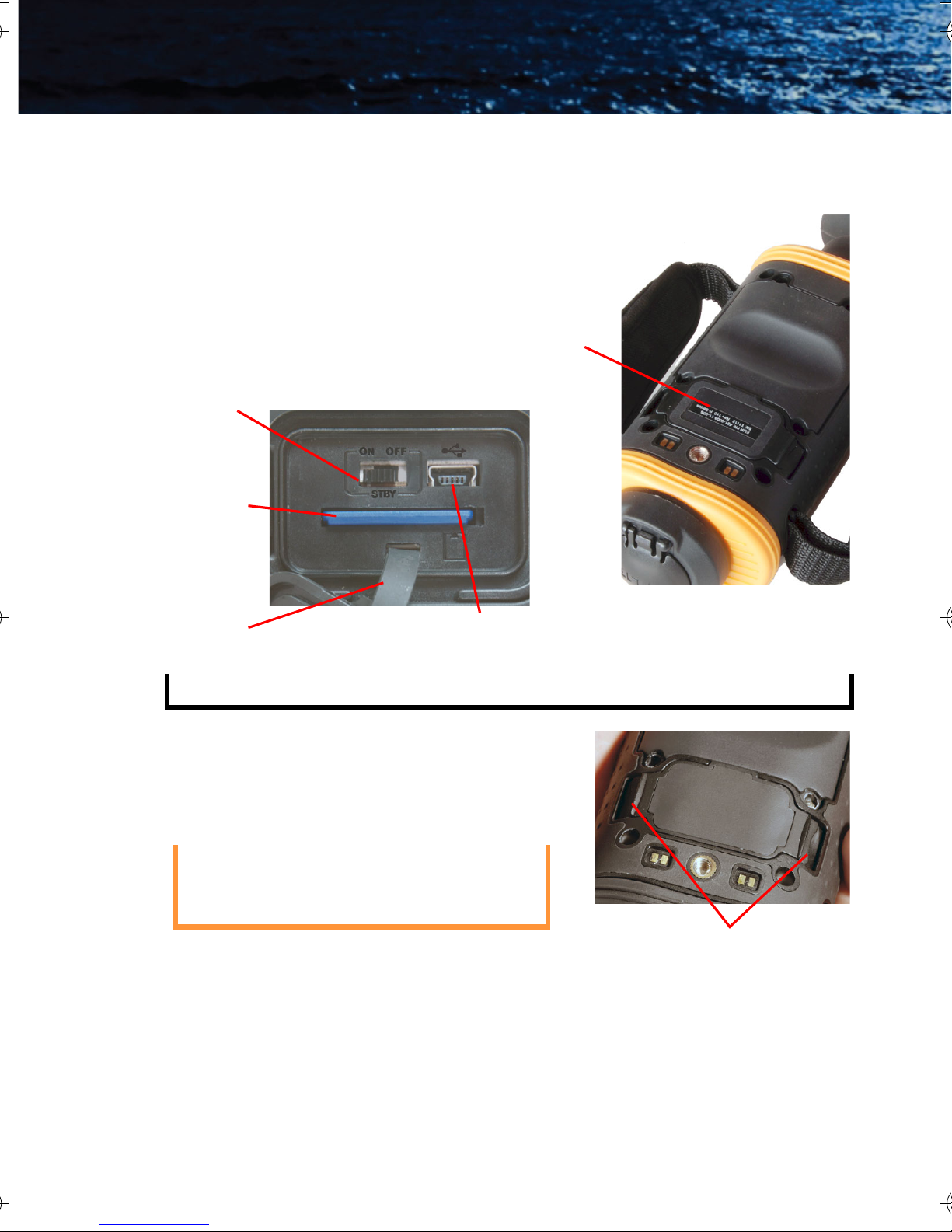
3–7 SD Card Door
The SD Card door is located on the
bottom of the camera in front of the
battery compartment. The SD card,
the USB connector, and the AutoStandby Enable switch are located
under the door. See “Auto-Standby
Operation” on page 23.
Auto-Standby Enable
switch
SD Card
Lanyard
USB
SD Card
door
Note
The Hot Shoe must be removed to access the SD Card door.
To open the SD Card door, grasp the
two edges with your thumb and finger
and pull straight up.
Caution!
Do not stretch or break the rubber
lanyard that keeps the door captive
to the camera when opened.
To close the SD Card door, slide the
lanyard strap back into the camera,
position the door in place, and then
firmly press in the middle of the door
until it is fully seated.
432-0004-00-10, Revision 100 21
Grasp SD Card door
edges and pull
Page 26
3—Operating Your HM-Series Camera HM-Series Operator’s Manual
SD Card Capacity and Type
The HM-224 Pro and HM-324 XP+ model cameras support storing
images and video (HM-324 XP+ only) on standard 1-Gb, 2-Gb, and 4Gb SD cards that are compliant with the SD 1.0 and 1.1 specification.
HM-Series cameras are not compatible with SDHC standards.
If an SD card is inserted into an HM-224 or HM-324 XP model, it will
be ignored unless the camera software detects a valid upgrade file. In
order to store images and video on the SD card, the HM-224 model
must be upgraded to an HM-224 Pro and the HM-324 XP model
must be upgraded to an HM-324 XP+. See “Installing Software
Upgrades” on page 28.
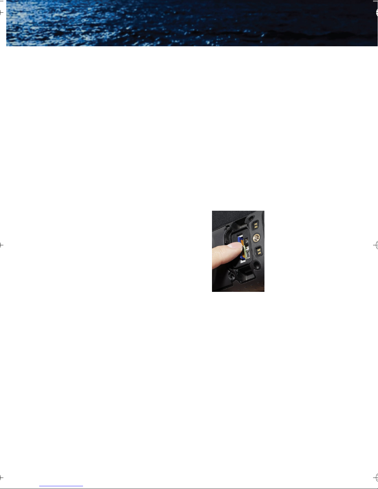
Installing an SD Card
To install an SD card, insert the card into
the slot and press on the SD card until its
edge is nearly flush with the surface and
release.
To remove an SD card, use this same
motion.
Downloading Stored Files via USB
The HM-224 Pro and HM-324 XP+ model cameras also support
downloading stored images and video via the USB port.
With the camera on, plug the USB cable into the USB connector on
the camera and a USB port on your computer.
Allow up to two minutes for the USB connection to be recognized by
the computer’s operating system.
22 January 2010
Page 27

HM-Series Operator’s Manual 3—Operating Your HM-Series Camera
3–8 Auto-Standby Operation
Auto-Standby is a feature of the HM-Series cameras that helps to
guard against draining the batteries prematurely by inadvertently
leaving the camera on. Auto-Standby puts the camera into the
Standby state if the following three conditions are met:
• The camera is in the On state.
• The Auto-Standby switch (STBY) is set to ON.
• No buttons have been pressed for three minutes.
Once these conditions are met you will
see the following message in the display
and the camera will enter the Standby
state after the countdown is finished:
Press any button during this countdown to terminate Auto-Standby
and resume normal operation.
Note
Pressing any button during an Auto-Standby countdown will only
terminate the countdown and abort the Auto-Standby.
The normal function of the button will not occur.
Auto-Standby Switch
Some use scenarios involving
unattended operation of the camera may
require disabling Auto-Standby.
Select OFF to turn off Auto-Standby.
Select ON to turn on Auto-Standby.
If Auto-Standby is off, a reminder message will
appear in the display each time the camera enters
the On state.
432-0004-00-10, Revision 100 23
Page 28

3—Operating Your HM-Series Camera HM-Series Operator’s Manual
3–9 The Hot Shoe
Note
The Hot Shoe is not waterproof and should not be used in wet
environments.
The Hot Shoe provides the
connections to power the camera for
continuous operation or charging the
batteries; and for accessing the
analog video output. The Hot Shoe
attaches to the bottom of the camera
and is secured via the tripod mount.
Power
The following steps are
recommended for quick and easy
attachment of the Hot Shoe.
1. With the camera positioned
bottom-side up, hold the Hot
Shoe in position.
2. Rotate the attachment wheel
in the clockwise direction until tight.
Video
3. To remove the Hot Shoe, simply
rotate the attachment wheel in the
counter-clockwise direction until it is
free.
24 January 2010
Page 29
HM-Series Operator’s Manual 3—Operating Your HM-Series Camera
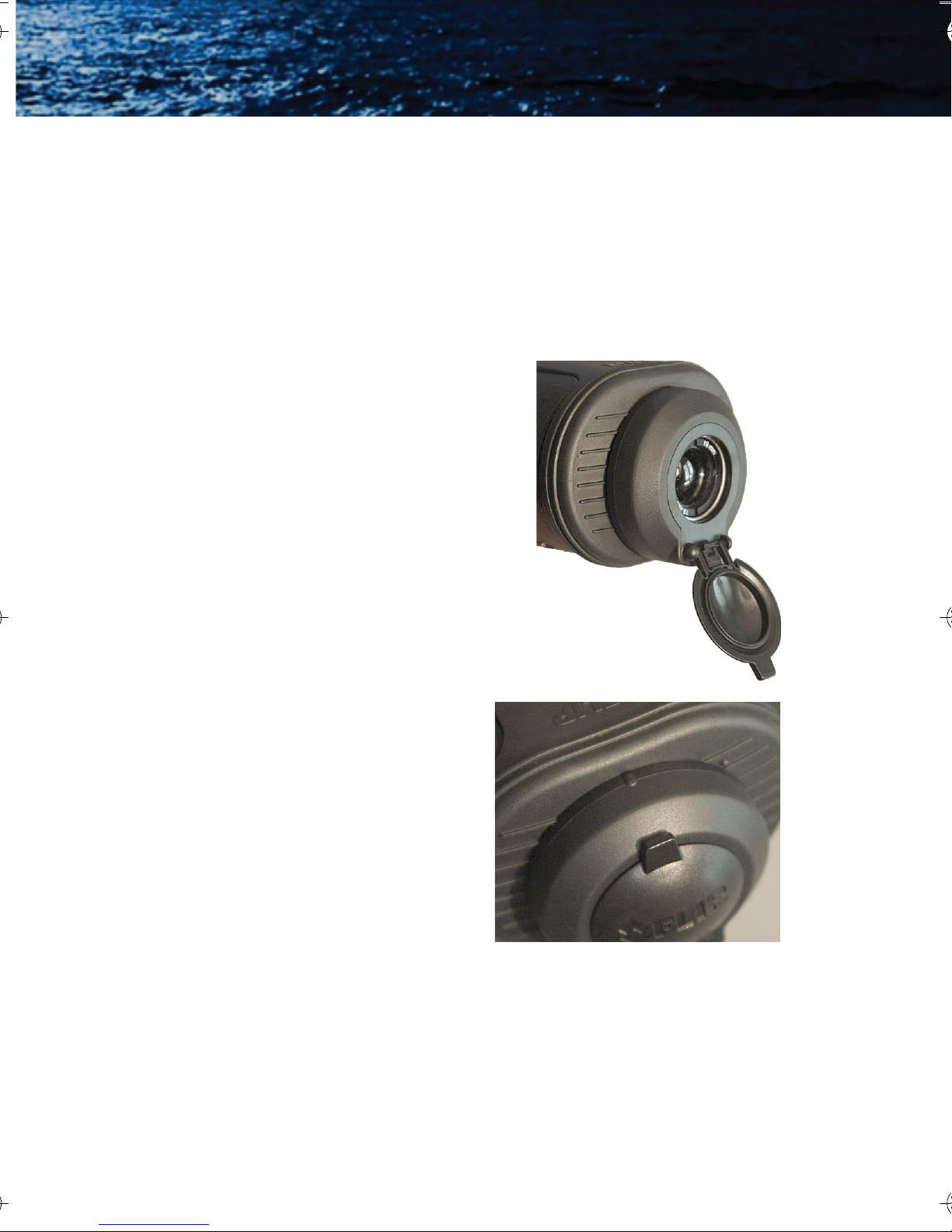
3–10 Installing the Shuttered Eyepiece
The shuttered eyepiece keeps light from coming out of the viewfinder
display. Pressing your eye up against the eyepiece opens the shutter.
The shutter closes automatically.
The eyepiece fits into a groove around the display housing.
Groove for eyepiece
When pressing the eyepiece into position, ensure that the diopter
lever is free to move.
Groove is still visible
If the eyepiece is pushed too far onto the display housing it will interfere
with the diopter lever.
432-0004-00-10, Revision 100 25
Page 30
3—Operating Your HM-Series Camera HM-Series Operator’s Manual
3–11 Bayonet Lens Mounting System
The HM-Series camera is equipped with a robust bayonet mounting
system to allow for field-interchangeable optics options. As shipped,
the camera comes with a lens-cover assembly mounted on the
bayonet mount.
Operation of the Lens-cover Assembly
The lens cover is a simple flip-to-open lens
cover that provides protection for the
camera lens when not in use. To open,
simply flip the lens cover down to the fully
open position (45° pointing toward the
ground as shown in the photograph at the
right).
To remove the lens-cover
assembly, rotate the outer ring
of the lens cover clockwise so
that the index mark on the top of
the lens cover aligns with the
index mark on the front body of
the camera (approximately 45°),
and pull straight off.
26 January 2010
Page 31

HM-Series Operator’s Manual 3—Operating Your HM-Series Camera
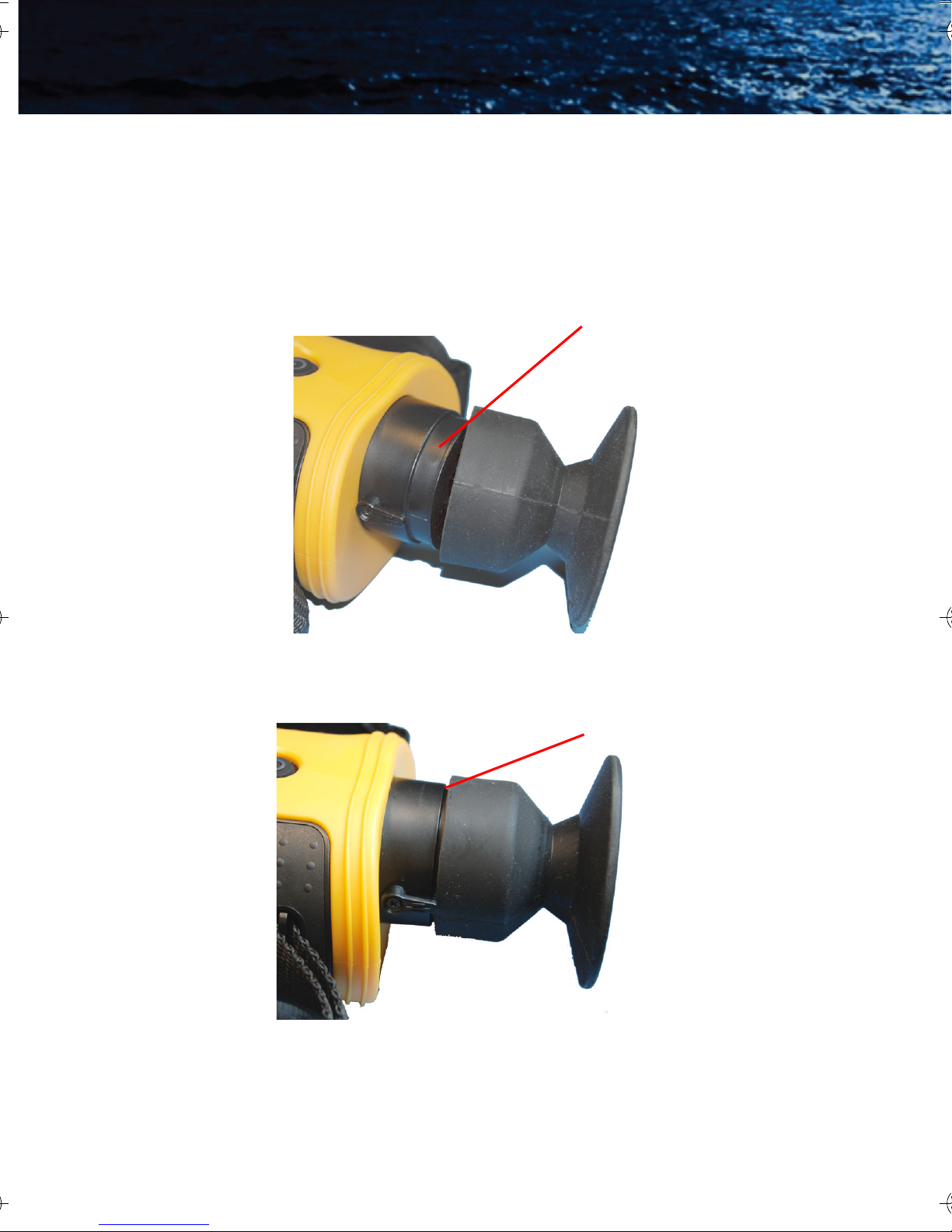
3–12 2× Extender
Note
The 2× Optical Extender is not waterproof and should not be used
in wet environments.
The 2× Optical Extender is compatible with all HM-Series camera
models and provides the user the ability to see farther and/or
enhance the resolution of objects in the field of view. The 2× Optical
Extender is mounted on the bayonet mount in front of the existing lens
on the camera.
To mount the 2× extender,
first remove the lens cover
assembly. Then, position the
2× extender so that the
release lever on the 2×
extender is in the 5 o’clock
position on the bayonet
mount. Firmly push the
extender onto the bayonet
mount, then rotate the lens
Release Lever
counter-clockwise so that the
release lever reaches the 3
o’clock position where it will hit a hard stop.
Note
The 2× extender is manually focused by rotating the outer rubbercoated ring.
To remove the 2× extender, press the release lever and rotate the
extender clockwise until the release lever is roughly at the 5 o’clock
position and pull straight off.
Caution!
Be sure to replace the lens cover assembly when the 2× Extender
is not in use to avoid moisture, dust, or other contaminants
reaching the inner lens surface of the 2× Extender.
432-0004-00-10, Revision 100 27
Page 32

3—Operating Your HM-Series Camera HM-Series Operator’s Manual
3–13 Installing Software Upgrades
Software upgrades may become available during the life of your HMSeries camera. The upgrade process requ ires a n SD car d load ed wit h
the upgrade file. After receiving the upgrade file from FLIR, load it onto
your SD card.
Caution!
During a software installation, the camera must remain powered
on. Turning off the camera, or losing power for any reason, may
damage the system files and require that the camera be returned
to the factory for repair.
Use the following procedure to install the upgrade:
1. Ensure that the camera battery is fully charged. (The software
installation will not start if the battery charge is less than 50%.)
2. With the camera off, install the SD card loaded with the upgrade
file. Refer to “SD Card Door” on page 21.
3. Install the Hot Shoe and connect to a power source. Refer to “The
Hot Shoe” on page 24.
4. Turn on the camera. During its Bootup process, the camera will
check the SD card for a valid upgrade file.
5. Watch the display. When a valid file is found, a message will be
shown for about ten seconds directing you to
“Press and hold Capture button for 2 seconds to initiate update.”
If you ignore the message, the camera will resume normal
operation and enter the On state.
6. While the message is displayed, press and hold the Capture
button for two seconds.
The software upgrade takes about four minutes and the camera
will reboot automatically when it is finished.
28 January 2010
Page 33

4Technical Data
4–1 HM-Series Camera Model Features
The HM-Series cameras are available with either NTSC or PAL video
output format and two resolutions. The HM-224 and HM-224 Pro
both have video resolution of 240 × 180 pixels, while the HM-324 XP
and HM-324 XP+ both have video resolution of 320 × 240 pixels.
HM-Series
Model
HM-224 HM-Series Handheld Thermal Camera with video resolution of
240 × 180 pixels
HM-224 Pro HM-Series Handheld Thermal Camera with video resolution of
240 × 180 pixels, 2
enabled USB2 port.
HM-324 XP HM-Series Handheld Thermal Camera with video resolution of
320 × 240 pixels, 2
× electronic zoom, still image capture, and
× electronic zoom.
HM-324 XP+ HM-Series Handheld Thermal Camera with video resolution of
320 × 240 pixels, 2
capture, and enabled USB2 port.
Hot Shoe Charging & Video Output Attachment, 4 Rechargeable
AA Batteries, AC Power Adapter/Charger, Car Adapter/Charger,
Neck Lanyard, Operator’s Manual, Video Output Cable, and USB
Cable
Feature
Start up from
stand-by
Thermal Sensitivity,
Waveband
Detector Type VOx Microbolometer
Resolution 240
Image Processing FLIR Proprietary Digital Detail Enhancement
Focus, Zoom Fixed focus, 2
Video Output NTSC or PAL composite video; RCA jack; <9 Hz frame rate
<1.5 seconds
<50 mK @ f/1.0,
7.5 - 13.5 μm
× 180 pixels HM-224 and HM-224 Pro
× 240 pixels HM-324 XP and HM-324 XP+
320
× electronic zoom, still image capture, video
× electronic zoom
432-0004-00-10, Revision 100 29
Page 34

4—Technical Data HM-Series Operator’s Manual
4–2 Power
Battery Types 4 AA Batteries; NiMH or Alkaline
Battery Life Operating
(Stand-By)
Approximately 5 Hours on NiMH batteries at 25°C,
(120 hours on NiMH batteries)
4–3 Environmental
HM-224 and
HM-224 Pro
Operational Temp. 32°F – 122°F
(0°C – 50°C)
Storage Temp. -4°F – 158°F
(-20°C – 70°C)
Ratings (not including the Hot Shoe
or the 2× Optical Extender)
IP-67, Submersible, 1 meter drop
HM-324 XP and
HM-324 XP+
-4°F – 140°F
(-20°C – 60°C)
-40°F – 167°F
(-40°C – 75°C)
4–4 Physical
Weight (incl. lens) 1.45 lb. (653 g) with batteries;
add 0.7 lb. (315 g) for 2
× extender
Size (L
× W × H) 10.42” × 3.33” × 2.62”
(256
× 84.5 × 66.5 mm)
4–5 Lens Choice
HM-Series
FOV 24°
FOV (w/Optional 2
× Extender) 12° × 9°
30 January 2010
× 18°
Page 35

HM-Series Operator’s Manual 4—Technical Data
4–6 Storage File Formats
HM-224 Pro
Still Image Storage,
Format
Video Storage,
Format
SD card, JPEG;
240
× 180 resolution
4–7 Range Detection
HM-224 HM-324 XP/with 2× Optical Extender
Detect Man
(1.8 m
Detect Vessel
(2.3 m
× 0.5 m)
× 2.3 m)
1,050’ (320 m) 1,500’ (450 m)/2,590’ (790 m)
2,940’ (900 m) 4,200’ (1.2 km)/1.3 mi. (2.15 km)
HM-324 XP and
HM-324 XP+
SD card, JPEG;
320 × 240 resolution
Approx. 8 seconds/Mb
on SD card,
HM-324 XP+ only
1
1. Actual range may vary depending on camera set-up,
environmental conditions, and user experience.
432-0004-00-10, Revision 100 31
Page 36

4—Technical Data HM-Series Operator’s Manual
32 January 2010
Page 37

Page 38

Santa Barbara Portland
FLIR Commercial Systems, Inc.
World Headquarters
FLIR Systems, Inc.
70 Castilian Dr.
Goleta, CA 93117
USA
PH: +1.888.747.FLIR
(+1.888.747.3547)
Europe
FLIR Commercial Systems B.V.
Charles Petitweg 21
4847 NW Teteringen - Breda
The Netherlands
PH: + 31 (0) 765 79 41 94
FLIR Corporate Headquarters
FLIR Systems, Inc.
27700A SW Parkway Ave.
Wilsonville, OR 97070
USA
FX: + 31 (0) 765 79 41 99
flir@flir.com
 Loading...