

Page 1
User’s manual
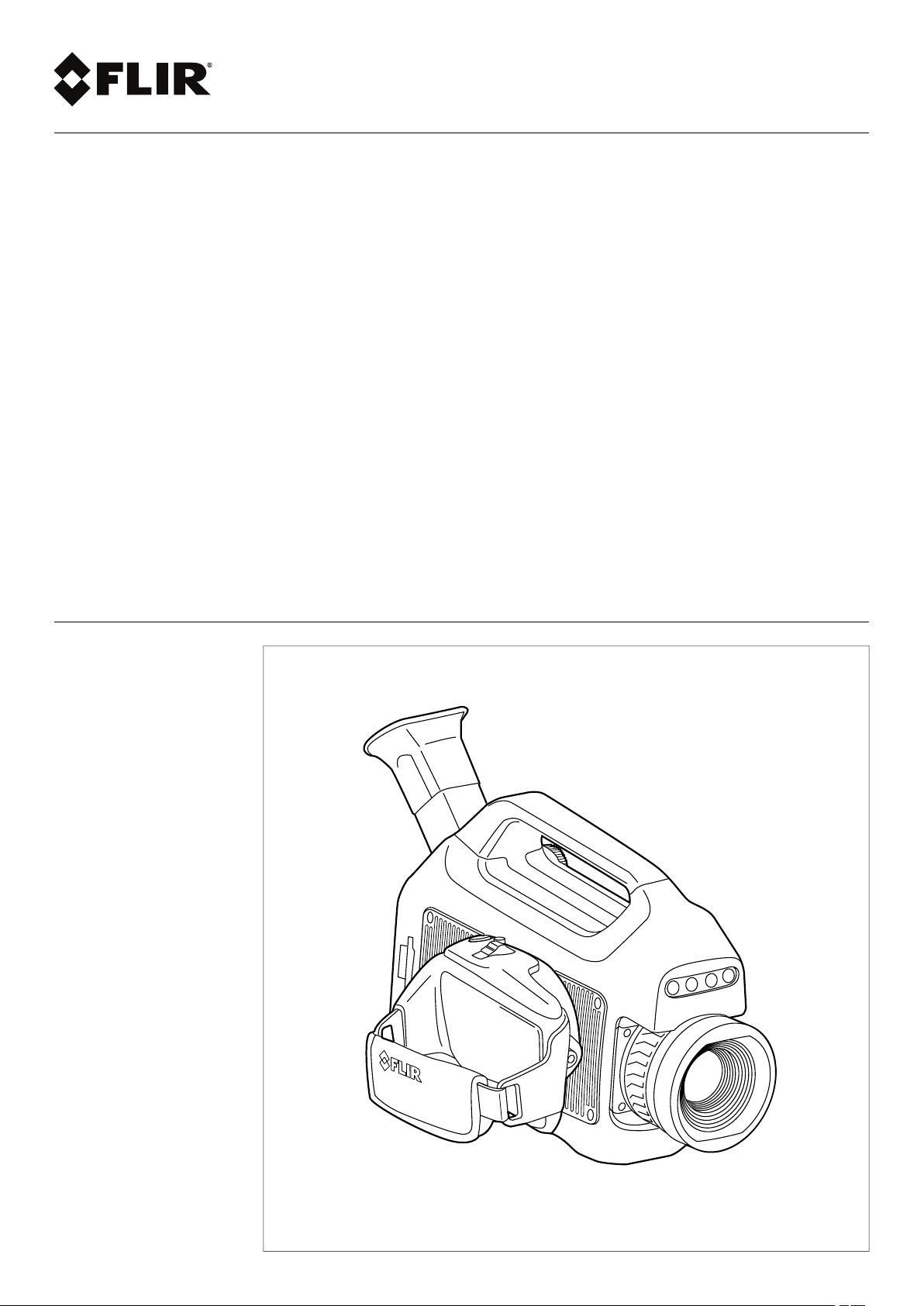
FLIR GFx3xx series
Page 2

Page 3

Page 4

Important note
Before operating the device, you must read, understand, and follow all instructions, warnings, cautions, and legal disclaimers.
Důležitá poznámka
Před použitím zařízení si přečtěte veškeré pokyny, upozornění, varování a vyvázání se ze záruky, ujistěte se, že jim rozumíte, a řiďte
se jimi.
Vigtig meddelelse
Før du betjener enheden, skal du du læse, forstå og følge alle anvisninger, advarsler, sikkerhedsforanstaltninger og
ansvarsfraskrivelser.
Wichtiger Hinweis
Bevor Sie das Gerät in Betrieb nehmen, lesen, verstehen und befolgen Sie unbedingt alle Anweisungen, Warnungen,
Vorsichtshinweise und Haftungsausschlüsse
Σημαντική σημείωση
Πριν από τη λειτουργία της συσκευής, πρέπει να διαβάσετε, να κατανοήσετε και να ακολουθήσετε όλες τις οδηγίες,
προειδοποιήσεις, προφυλάξεις και νομικές αποποιήσεις.
Nota importante
Antes de usar el dispositivo, debe leer, comprender y seguir toda la información sobre instrucciones, advertencias, precauciones y
renuncias de responsabilidad.
Tärkeä huomautus
Ennen laitteen käyttämistä on luettava ja ymmärrettävä kaikki ohjeet, vakavat varoitukset, varoitukset ja lakitiedotteet sekä
noudatettava niitä.
Remarque importante
Avant d'utiliser l'appareil, vous devez lire, comprendre et suivre l'ensemble des instructions, avertissements, mises en garde et
clauses légales de non-responsabilité.
Fontos megjegyzés
Az eszköz használata előtt figyelmesen olvassa el és tartsa be az összes utasítást, figyelmeztetést, óvintézkedést és jogi
nyilatkozatot.
Nota importante
Prima di utilizzare il dispositivo, è importante leggere, capire e seguire tutte le istruzioni, avvertenze, precauzioni ed esclusioni di
responsabilità legali.
重要な注意
デバイスをご使用になる前に、あらゆる指示、警告、注意事項、および免責条項をお読み頂き、その内容を理解して従ってくだ
さい。
중요한 참고 사항
장치를 작동하기 전에 반드시 다음의 사용 설명서와 경고, 주의사항, 법적 책임제한을 읽고 이해하며 따라야 합니다.
Viktig
Før du bruker enheten, må du lese, forstå og følge instruksjoner, advarsler og informasjon om ansvarsfraskrivelse.
Belangrijke opmerking
Zorg ervoor dat u, voordat u het apparaat gaat gebruiken, alle instructies, waarschuwingen en juridische informatie hebt
doorgelezen en begrepen, en dat u deze opvolgt en in acht neemt.
Ważna uwaga
Przed rozpoczęciem korzystania z urządzenia należy koniecznie zapoznać się z wszystkimi instrukcjami, ostrzeżeniami,
przestrogami i uwagami prawnymi. Należy zawsze postępować zgodnie z zaleceniami tam zawartymi.
Nota importante
Antes de utilizar o dispositivo, deverá proceder à leitura e compreensão de todos os avisos, precauções, instruções e isenções de
responsabilidade legal e assegurar-se do seu cumprimento.
Важное примечание
До того, как пользоваться устройством, вам необходимо прочитать и понять все предупреждения, предостережения и
юридические ограничения ответственности и следовать им.
Viktig information
Innan du använder enheten måste du läsa, förstå och följa alla anvisningar, varningar, försiktighetsåtgärder och
ansvarsfriskrivningar.
Önemli not
Cihazı çalıştırmadan önce tüm talimatları, uyarıları, ikazları ve yasal açıklamaları okumalı, anlamalı ve bunlara uymalısınız.
重要注意事项
在操作设备之前,您必须阅读、理解并遵循所有说明、警告、注意事项和法律免责声明。
重要注意事項
操作裝置之前,您務必閱讀、了解並遵循所有說明、警告、注意事項與法律免責聲明。
Page 5

User’s manual
FLIR GFx3xx series
#T810169; r. AN/42241/42268; en-US
v
Page 6

Page 7

Table of contents
1 Disclaimers ......................................................................................1
1.1 Legal disclaimer ....................................................................... 1
1.2 U.S. Government Regulations......................................................1
1.3 Copyright ................................................................................ 1
1.4 Quality assurance ..................................................................... 2
1.5 Patents...................................................................................2
1.6 EULA Terms ............................................................................ 2
1.7 EULA Terms ............................................................................ 3
2 Safety information ............................................................................. 4
2.1 Cautions and warnings related to a classified (hazardous)
2.2 General cautions and warnings ....................................................5
3 Notice to user ................................................................................. 11
3.1 User-to-user forums ................................................................ 11
3.2 Calibration............................................................................. 11
3.3 Accuracy .............................................................................. 11
3.4 Disposal of electronic waste ...................................................... 11
3.5 Training ................................................................................ 11
3.6 Documentation updates ........................................................... 11
3.7 Note about authoritative versions................................................ 12
4 Customer help ................................................................................ 13
4.1 General ................................................................................ 13
4.2 Submitting a question .............................................................. 13
4.3 Downloads ............................................................................ 14
5 Conditions of Use for Ex Equipment .................................................. 15
6 Important note about training and applications ................................... 16
6.1 General ................................................................................ 16
7 Important information about FLIR GFx3xx series service ..................... 17
8 List of accessories and services ....................................................... 18
9 Introduction.................................................................................... 21
10 Example images .............................................................................. 22
10.1 General ................................................................................ 22
10.2 Images ................................................................................. 22
11 Quick start guide ............................................................................. 23
11.1 Starting the camera for the first time............................................ 23
11.2 Detecting a gas leak ................................................................ 27
11.3 Detecting a temperature ........................................................... 28
12 FLIR GFx3xx series general instrument check .................................... 31
13 A note about ergonomics ................................................................. 32
13.1 General ................................................................................ 32
area.......................................................................................4
2.2.1 Table of entity parameters ................................................ 8
2.2.2 Battery warning label ......................................................8
2.2.3 Laser warning label......................................................... 9
2.2.4 Laser rules and regulations .............................................. 9
2.2.5 Compliance marking ....................................................... 9
2.2.6 Applicable markings ..................................................... 10
2.2.7 Certifications............................................................... 10
2.2.8 Explosive (hazardous) environment ................................. 10
2.2.9 Safety........................................................................ 10
11.2.1 Procedure .................................................................. 27
11.2.2 Related topics ............................................................. 28
11.3.1 Procedure .................................................................. 28
11.3.2 Related topics ............................................................. 29
#T810169; r. AN/42241/42268; en-US
vii
Page 8

Table of contents
13.2 Figure .................................................................................. 32
13.3 Related topics ........................................................................ 33
14 Camera parts .................................................................................. 34
14.1 View from the left .................................................................... 34
14.1.1 Figure........................................................................ 34
14.1.2 Explanation................................................................. 34
14.2 View from the right .................................................................. 35
14.2.1 Figure........................................................................ 35
14.2.2 Explanation................................................................. 35
14.3 View from the rear................................................................... 36
14.3.1 Figure........................................................................ 36
14.3.2 Explanation................................................................. 36
14.4 View from the rear with open cover ............................................. 37
14.4.1 Figure........................................................................ 37
14.4.2 Explanation................................................................. 37
14.5 Battery condition LED indicator .................................................. 38
14.5.1 Figure........................................................................ 38
14.5.2 Explanation................................................................. 38
14.6 Power LED indicator ................................................................ 38
14.6.1 Figure........................................................................ 38
14.6.2 Explanation................................................................. 38
14.7 Laser pointer ......................................................................... 39
14.7.1 General...................................................................... 39
14.7.2 Figure........................................................................ 39
14.7.3 Laser warning label....................................................... 39
14.7.4 Laser rules and regulations ............................................ 39
14.8 Serial number ........................................................................ 40
14.8.1 General...................................................................... 40
14.8.2 Figure........................................................................ 40
15 Screen elements ............................................................................. 41
15.1 Mode selector ........................................................................ 41
15.1.1 Figure........................................................................ 41
15.1.2 Explanation................................................................. 41
15.2 Result table and measurement tools ........................................... 41
15.2.1 Figure........................................................................ 41
15.2.2 Explanation................................................................. 41
15.3 Toolbox, indicators, and other objects.......................................... 41
15.3.1 Figure........................................................................ 42
15.3.2 Explanation................................................................. 42
16 Achieving a good image ................................................................... 43
16.1 General ................................................................................ 43
16.2 Adjusting the infrared camera focus ............................................ 43
16.2.1 Figure........................................................................ 43
16.2.2 Procedure .................................................................. 43
16.3 Adjusting an image.................................................................. 43
16.3.1 General...................................................................... 43
16.3.2 Explanation of the adjustment methods ............................. 44
16.3.3 Procedure (Auto).......................................................... 44
16.3.4 Figure........................................................................ 44
16.3.5 Procedure (HSM) ......................................................... 44
16.3.6 Procedure (Manual)...................................................... 44
16.4 Selecting a suitable temperature range ........................................ 44
16.4.1 About temperature ranges.............................................. 44
16.4.2 Understanding the temperature scale ............................... 45
16.4.3 Changing the temperature range ..................................... 46
#T810169; r. AN/42241/42268; en-US
viii
Page 9

Table of contents
16.5 Selecting a suitable color palette ................................................ 46
16.5.1 Procedure .................................................................. 46
16.6 Enabling or disabling histogram mode ......................................... 46
16.6.1 General...................................................................... 46
16.6.2 Procedure .................................................................. 46
16.7 Enabling or disabling inverted color palette................................... 46
16.7.1 Procedure .................................................................. 46
16.8 Changing object parameters ..................................................... 47
16.8.1 General...................................................................... 47
16.8.2 Types of parameters ..................................................... 47
16.8.3 Recommended values................................................... 47
16.8.4 Procedure .................................................................. 47
16.8.5 Related topics ............................................................. 48
17 Connecting external devices............................................................. 49
17.1 General ................................................................................ 49
17.2 Figure .................................................................................. 49
17.3 Explanation ........................................................................... 49
17.4 Formatting memory cards ......................................................... 49
18 Handling the camera ........................................................................ 51
18.1 Charging the camera battery ..................................................... 51
18.1.1 Charging the battery using the power supply cable .............. 51
18.1.2 Charging the battery using the stand-alone battery
charger ...................................................................... 51
18.2 Installing and removing the camera battery................................... 52
18.2.1 Installing the battery...................................................... 52
18.2.2 Removing the battery .................................................... 52
18.3 Turning on the camera ............................................................. 53
18.3.1 Procedure .................................................................. 53
18.4 Turning off the camera ............................................................. 53
18.4.1 Procedure .................................................................. 53
18.5 Adjusting the viewing angle of the viewfinder................................. 54
18.5.1 General...................................................................... 54
18.5.2 Figure........................................................................ 54
18.5.3 Procedure .................................................................. 54
18.6 Adjusting the viewfinder’s dioptric correction ................................. 54
18.6.1 General...................................................................... 54
18.6.2 Figure........................................................................ 54
18.6.3 Procedure .................................................................. 55
18.7 Adjusting the camera grip ......................................................... 55
18.7.1 General...................................................................... 55
18.7.2 Figure........................................................................ 55
18.7.3 Procedure .................................................................. 55
18.8 Opening the display................................................................. 55
18.8.1 Figure........................................................................ 55
18.9 Adjusting the viewing angle of the display..................................... 56
18.9.1 General...................................................................... 56
18.9.2 Figure........................................................................ 56
18.9.3 Procedure .................................................................. 56
18.10 Adjusting the infrared camera focus ............................................ 56
18.10.1 Figure........................................................................ 56
18.10.2 Procedure .................................................................. 57
18.11 Using the zoom function ........................................................... 57
18.11.1 General...................................................................... 57
18.11.2 Procedure .................................................................. 57
18.12 Operating the laser pointer........................................................ 58
#T810169; r. AN/42241/42268; en-US
ix
Page 10

Table of contents
18.12.1 Figure........................................................................ 58
18.12.2 Procedure .................................................................. 58
18.13 Laser warning label ................................................................. 58
18.14 Laser rules and regulations ....................................................... 58
18.15 Assigning functions to the programmable button............................ 59
18.15.1 General...................................................................... 59
18.15.2 Procedure .................................................................. 59
19 Working with views and images......................................................... 60
19.1 Saving infrared images............................................................. 60
19.1.1 General...................................................................... 60
19.1.2 Image capacity ............................................................ 60
19.1.3 Saving an infrared image directly to an SD Memory
Card.......................................................................... 60
19.1.4 Previewing and saving an infrared image to an SD
Memory Card .............................................................. 60
19.2 Opening an image................................................................... 61
19.2.1 General...................................................................... 61
19.2.2 Procedure .................................................................. 61
19.3 Changing settings related to image presentation............................ 61
19.3.1 General...................................................................... 61
19.3.2 Procedure .................................................................. 61
19.4 Editing a saved image.............................................................. 62
19.4.1 General...................................................................... 62
19.4.2 Procedure .................................................................. 62
19.5 Deleting a file ......................................................................... 62
19.5.1 Procedure .................................................................. 62
20 Working with measurement tools ...................................................... 63
20.1 Laying out a measurement tool .................................................. 63
20.1.1 General...................................................................... 63
20.1.2 Procedure .................................................................. 63
20.2 Moving or resizing a measurement tool........................................ 63
20.2.1 General...................................................................... 63
20.2.2 Procedure .................................................................. 63
20.3 Creating & setting up a difference calculation ................................ 63
20.3.1 General...................................................................... 63
20.3.2 Procedure .................................................................. 63
20.4 Changing object parameters ..................................................... 64
20.4.1 General...................................................................... 64
20.4.2 Types of parameters ..................................................... 64
20.4.3 Recommended values................................................... 65
20.4.4 Procedure .................................................................. 65
20.4.5 Related topics ............................................................. 65
21 Programming the camera ................................................................. 66
21.1 General ................................................................................ 66
21.2 Procedure ............................................................................. 66
22 Recording video clips ...................................................................... 67
22.1 General ................................................................................ 67
22.2 Procedure ............................................................................. 67
23 Changing settings ........................................................................... 68
23.1 General ................................................................................ 68
23.2 Procedure ............................................................................. 68
24 Technical data................................................................................. 69
24.1 Online field-of-view calculator .................................................... 69
24.2 Note about technical data ......................................................... 69
24.3 Note about authoritative versions................................................ 69
#T810169; r. AN/42241/42268; en-US
x
Page 11

Table of contents
24.4 FLIR GFx320 14.5° fixed lens .................................................... 70
24.5 FLIR GFx320 24° fixed lens....................................................... 75
25 Mechanical drawings ....................................................................... 80
26 EU Declaration of conformity ............................................................ 83
27 MET Compliance Data Report (truncated)........................................... 85
28 IEC/IECEE/Intertek Test Report (truncated)......................................... 88
29 IEC/IECEE/Intertek CB Test Certificate ............................................... 91
30 MET Laboratories Test Certificate (truncated) ..................................... 94
31 MET Laboratories Letter of Certification ............................................. 96
32 Element Type Examination Certificate (truncated) ............................... 98
33 IECEx Technical Report: GB/EMT/ExTR16.0015/00 ............................ 100
34 IECEx Quality Assessment Report: GB/EMT/QAR16.0003/00 .............. 102
35 Cleaning the camera ...................................................................... 104
35.1 Camera housing, cables, and other items................................... 104
35.1.1 Liquids..................................................................... 104
35.1.2 Equipment................................................................ 104
35.1.3 Procedure ................................................................ 104
35.2 Infrared lens ........................................................................ 104
35.2.1 Liquids..................................................................... 104
35.2.2 Equipment................................................................ 104
35.2.3 Procedure ................................................................ 104
36 Cooler maintenance....................................................................... 105
36.1 General .............................................................................. 105
36.2 Signs to watch for ................................................................. 105
37 Detectable gases........................................................................... 106
37.1 General .............................................................................. 106
37.2 Gases that can be detected by FLIR GFx3xx .............................. 106
38 Why do some gases absorb infrared energy? ................................... 109
39 About FLIR Systems ...................................................................... 112
39.1 More than just an infrared camera ............................................ 113
39.2 Sharing our knowledge .......................................................... 113
39.3 Supporting our customers....................................................... 114
40 Terms, laws, and definitions............................................................ 115
41 Thermographic measurement techniques ........................................ 117
41.1 Introduction ........................................................................ 117
41.2 Emissivity............................................................................ 117
41.2.1 Finding the emissivity of a sample.................................. 117
41.3 Reflected apparent temperature............................................... 121
41.4 Distance ............................................................................. 121
41.5 Relative humidity .................................................................. 121
41.6 Other parameters.................................................................. 121
42 About calibration ........................................................................... 122
42.1 Introduction ......................................................................... 122
42.2 Definition—what is calibration? ................................................ 122
42.3 Camera calibration at FLIR Systems ......................................... 122
42.4 The differences between a calibration performed by a user and
that performed directly at FLIR Systems..................................... 123
42.5 Calibration, verification and adjustment...................................... 123
42.6 Non-uniformity correction........................................................ 124
42.7 Thermal image adjustment (thermal tuning) ................................ 124
#T810169; r. AN/42241/42268; en-US
xi
Page 12

Table of contents
43 History of infrared technology......................................................... 125
44 Theory of thermography................................................................. 128
44.1 Introduction ......................................................................... 128
44.2 The electromagnetic spectrum................................................. 128
44.3 Blackbody radiation............................................................... 128
44.3.1 Planck’s law .............................................................. 129
44.3.2 Wien’s displacement law.............................................. 130
44.3.3 Stefan-Boltzmann's law ............................................... 131
44.3.4 Non-blackbody emitters ............................................... 132
44.4 Infrared semi-transparent materials........................................... 134
45 The measurement formula.............................................................. 135
46 Emissivity tables ........................................................................... 139
46.1 References.......................................................................... 139
46.2 Tables ................................................................................ 139
#T810169; r. AN/42241/42268; en-US
xii
Page 13

1
Disclaimers
1.1 Legal disclaimer
All products manufactured by FLIR Systems are warranted against defective materials
and workmanship for a period of one (1) year from the delivery date of the original purchase, provided such products have been under normal storage, use and service, and in
accordance with FLIR Systems instruction.
Uncooled handheld infrared cameras manufactured by FLIR Systems are warranted
against defective materials and workmanship for a period of two (2) years from the delivery date of the original purchase, provided such products have been under normal storage, use and service, and in accordance with FLIR Systems instruction, and provided
that the camera has been registered within 60 days of original purchase.
Detectors for uncooled handheld infrared cameras manufactured by FLIR Systems are
warranted against defective materials and workmanship for a period of ten (10) years
from the delivery date of the original purchase, provided such products have been under
normal storage, use and service, and in accordance with FLIR Systems instruction, and
provided that the camera has been registered within 60 days of original purchase.
Products which are not manufactured by FLIR Systems but included in systems delivered by FLIR Systems to the original purchaser, carry the warranty, if any, of the particular supplier only. FLIR Systems has no responsibility whatsoever for such products.
The warranty extends only to the original purchaser and is not transferable. It is not applicable to any product which has been subjected to misuse, neglect, accident or abnormal
conditions of operation. Expendable parts are excluded from the warranty.
In the case of a defect in a product covered by this warranty the product must not be further used in order to prevent additional damage. The purchaser shall promptly report any
defect to FLIR Systems or this warranty will not apply.
FLIR Systems will, at its option, repair or replace any such defective product free of
charge if, upon inspection, it proves to be defective in material or workmanship and provided that it is returned to FLIR Systems within the said one-year period.
FLIR Systems has no other obligation or liability for defects than those set forth above.
No other warranty is expressed or implied. FLIR Systems specifically disclaims the im-
plied warranties of merchantability and fitness for a particular purpose.
FLIR Systems shall not be liable for any direct, indirect, special, incidental or consequen-
tial loss or damage, whether based on contract, tort or any other legal theory.
This warranty shall be governed by Swedish law.
Any dispute, controversy or claim arising out of or in connection with this warranty, shall
be finally settled by arbitration in accordance with the Rules of the Arbitration Institute of
the Stockholm Chamber of Commerce. The place of arbitration shall be Stockholm. The
language to be used in the arbitral proceedings shall be English.
1.2 U.S. Government Regulations
This product may be subject to U.S. Export Regulations. Please send any inquiries to exportquestions@flir.com.
1.3 Copyright
© 2016, FLIR Systems, Inc. All rights reserved worldwide. No parts of the software including source code may be reproduced, transmitted, transcribed or translated into any
language or computer language in any form or by any means, electronic, magnetic, optical, manual or otherwise, without the prior written permission of FLIR Systems.
The documentation must not, in whole or part, be copied, photocopied, reproduced,
translated or transmitted to any electronic medium or machine readable form without prior consent, in writing, from FLIR Systems.
#T810169; r. AN/42241/42268; en-US
1
Page 14

Disclaimers1
Names and marks appearing on the products herein are either registered trademarks or
trademarks of FLIR Systems and/or its subsidiaries. All other trademarks, trade names
or company names referenced herein are used for identification only and are the property of their respective owners.
1.4 Quality assurance
The Quality Management System under which these products are developed and manufactured has been certified in accordance with the ISO 9001 standard.
FLIR Systems is committed to a policy of continuous development; therefore we reserve
the right to make changes and improvements on any of the products without prior notice.
1.5 Patents
000439161; 000653423; 000726344; 000859020; 001707738; 001707746; 001707787;
001776519; 001954074; 002021543; 002021543-0002; 002058180; 002249953;
002531178; 002816785; 002816793; 011200326; 014347553; 057692; 061609;
07002405; 100414275; 101796816; 101796817; 101796818; 102334141; 1062100;
11063060001; 11517895; 1226865; 12300216; 12300224; 1285345; 1299699;
1325808; 1336775; 1391114; 1402918; 1404291; 1411581; 1415075; 1421497;
1458284; 1678485; 1732314; 17399650; 1880950; 1886650; 2007301511414;
2007303395047; 2008301285812; 2009301900619; 20100060357; 2010301761271;
2010301761303; 2010301761572; 2010305959313; 2011304423549; 2012304717443;
2012306207318; 2013302676195; 2015202354035; 2015304259171; 204465713;
204967995; 2106017; 2107799; 2115696; 2172004; 2315433; 2381417; 2794760001;
3006596; 3006597; 303330211; 4358936; 483782; 484155; 4889913; 4937897;
4995790001; 5177595; 540838; 579475; 584755; 599392; 60122153; 6020040116815;
602006006500.0; 6020080347796; 6020110003453; 615113; 615116; 664580; 664581;
665004; 665440; 67023029; 6707044; 677298; 68657; 69036179; 70022216;
70028915; 70028923; 70057990; 7034300; 710424; 7110035; 7154093; 7157705;
718801; 723605; 7237946; 7312822; 7332716; 7336823; 734803; 7544944; 7606484;
7634157; 7667198; 7809258; 7826736; 8018649; 8153971; 8212210; 8289372;
8340414; 8354639; 8384783; 8520970; 8565547; 8595689; 8599262; 8654239;
8680468; 8803093; 8823803; 8853631; 8933403; 9171361; 9191583; 9279728;
9280812; 9338352; 9423940; 9471970; 9595087; D549758.
1.6 EULATerms
• You have acquired a device (“INFRARED CAMERA”) that includes software licensed
by FLIR Systems AB from Microsoft Licensing, GP or its affiliates (“MS”). Those installed software products of MS origin, as well as associated media, printed materials,
and “online” or electronic documentation (“SOFTWARE”) are protected by international intellectual property laws and treaties. The SOFTWARE is licensed, not sold. All
rights reserved.
• IF YOU DO NOT AGREE TO THIS END USER LICENSE AGREEMENT (“EULA”), DO
NOT USE THE DEVICE OR COPY THE SOFTWARE. INSTEAD, PROMPTLYCONTACT FLIR Systems AB FOR INSTRUCTIONS ON RETURN OF THE UNUSED DEVICE(S) FOR A REFUND. ANY USE OF THE SOFTWARE, INCLUDING BUT NOT
LIMITED TO USE ON THE DEVICE, WILL CONSTITUTE YOUR AGREEMENT TO
THIS EULA (OR RATIFICATION OF ANY PREVIOUS CONSENT).
• GRANT OF SOFTWARE LICENSE. This EULA grants you the following license:
◦ You may use the SOFTWARE only on the DEVICE.
◦ NOT FAULT TOLERANT. THE SOFTWARE IS NOT FAULT TOLERANT. FLIR Sys-
tems AB HAS INDEPENDENTLY DETERMINED HOW TO USE THE SOFTWARE
IN THE DEVICE, AND MS HAS RELIED UPON FLIR Systems AB TO CONDUCT
SUFFICIENT TESTING TO DETERMINE THAT THE SOFTWARE IS SUITABLE
FOR SUCH USE.
◦ NO WARRANTIES FOR THE SOFTWARE. THE SOFTWARE is provided “AS IS”
and with all faults. THE ENTIRE RISK AS TO SATISFACTORY QUALITY, PERFORMANCE, ACCURACY, AND EFFORT (INCLUDING LACK OF NEGLIGENCE)
IS WITH YOU. ALSO, THERE IS NO WARRANTYAGAINST INTERFERENCE
#T810169; r. AN/42241/42268; en-US
2
Page 15

Disclaimers1
WITH YOUR ENJOYMENT OF THE SOFTWARE OR AGAINST INFRINGEMENT.
IF YOU HAVE RECEIVED ANY WARRANTIES REGARDING THE DEVICE OR
THE SOFTWARE, THOSE WARRANTIES DO NOT ORIGINATE FROM, AND
ARE NOT BINDING ON, MS.
◦ No Liability for Certain Damages. EXCEPT AS PROHIBITED BY LAW, MS SHALL
HAVE NO LIABILITY FOR ANY INDIRECT, SPECIAL, CONSEQUENTIAL OR INCIDENTAL DAMAGES ARISING FROM OR IN CONNECTION WITH THE USE
OR PERFORMANCE OF THE SOFTWARE. THIS LIMITATION SHALL APPLY
EVEN IF ANY REMEDY FAILS OF ITS ESSENTIAL PURPOSE. IN NO EVENT
SHALL MS BE LIABLE FOR ANY AMOUNT IN EXCESS OF U.S. TWO HUNDRED FIFTY DOLLARS (U.S.$250.00).
◦ Limitations on Reverse Engineering, Decompilation, and Disassembly. You
may not reverse engineer, decompile, or disassemble the SOFTWARE, except and
only to the extent that such activity is expressly permitted by applicable law notwithstanding this limitation.
◦ SOFTWARE TRANSFER ALLOWED BUT WITH RESTRICTIONS. You may per-
manently transfer rights under this EULA only as part of a permanent sale or transfer of the Device, and only if the recipient agrees to this EULA. If the SOFTWARE
is an upgrade, any transfer must also include all prior versions of the SOFTWARE.
◦ EXPORT RESTRICTIONS. You acknowledge that SOFTWARE is subject to U.S.
export jurisdiction. You agree to comply with all applicable international and national laws that apply to the SOFTWARE, including the U.S. Export Administration
Regulations, as well as end-user, end-use and destination restrictions issued by U.
S. and other governments. For additional information see http://www.microsoft.
com/exporting/.
1.7 EULATerms
Qt4 Core and Qt4 GUI, Copyright ©2013 Nokia Corporation and FLIR Systems AB. This
Qt library is a free software; you can redistribute it and/or modify it under the terms of the
GNU Lesser General Public License as published by the Free Software Foundation; either version 2.1 of the License, or (at your option) any later version. This library is distributed in the hope that it will be useful, but WITHOUT ANY WARRANTY; without even the
implied warranty of MERCHANTABILITY or FITNESS FOR A PARTICULAR PURPOSE.
See the GNU Lesser General Public License, http://www.gnu.org/licenses/lgpl-2.1.html.
The source code for the libraries Qt4 Core and Qt4 GUI may be requested from FLIR
Systems AB.
#T810169; r. AN/42241/42268; en-US
3
Page 16
2
Safety information
2.1 Cautions and warnings related to a classified (hazardous) area
WARNING
Do not connect the camera to an external device while the camera is in a classified (hazardous) area.
An explosion can occur. This can cause injury or death to persons and damage to the equipment.
WARNING
Do not replace the memory card while the camera is in a classified (hazardous) area. An explosion can
occur. This can cause injury or death to persons and damage to the equipment.
WARNING
Do not open the cover for the connector and battery compartment while the camera is in a classified
(hazardous) area. An explosion can occur. This can cause injury or death to persons and damage to
the equipment.
WARNING
Do not replace the battery while the camera is in a classified (hazardous) area. An explosion can occur.
This can cause injury or death to persons and damage to the equipment.
WARNING
Only connect ATEX/IECEx-approved intrinsically safe equipment to the USB mini-B and HDMI ports. If
you do not obey this, an explosion can occur. This can cause injury or death to persons and damage to
the equipment.
WARNING
Do not charge the battery in a classified (hazardous) area. An explosion can occur. This can cause injury or death to persons and damage to the equipment.
WARNING
Do not take the following items (that FLIR Systems supplies) into a classified (hazardous) area. An explosion can occur. This can cause injury or death to persons and damage to the equipment.
Product name Item part number Sales part number
Battery charger, incl. power
supply with multi plugs
Cigarette lighter adapter kit, 12
VDC, 1.2 m/3.9 ft.
Hard transport case T199466
HDMI to DVI cable 1.5 m T910816 T910816ACC
HDMI to HDMI cable 1.5 m T910815
Screwdriver TX20
Power supply, incl. multi plugs T910814 T910814
USB cable Std A <-> Mini-B
1196210 T197692
1910490 T198509
T199466ACC
T910815ACC
T911309
1910423 1910423
T911309ACC
CAUTION
You must only use this charger when you charge the battery: Manufactured by Ten Pao industrial Co.
Ltd., IECEE CB reference certificate No. JPTUV-035588-M1 (supplied by TUV Rheinland Japan Ltd.),
FLIR item part number 1196210 (FLIR sales part number T197692). FLIR Systems supplies the charger
and the battery packs with the camera equipment. If you do not obey this, damage to the equipment
can occur and the protection that the equipment gives can become unsatisfactory.
#T810169; r. AN/42241/42268; en-US
4
Page 17
2
Safety information
CAUTION
Only use the camera with a battery that has the item part number T199183 on it (that FLIR Systems
supplies). If you do not obey this, damage to the equipment can occur and the protection that the equipment gives can become unsatisfactory.
CAUTION
Only use the camera with the following accessories (that FLIR Systems supplies). If you do not obey
this, the protection that the equipment gives can become unsatisfactory.
Product name Item part number Sales part number
Hand strap T129728 T129728ACC
Neck strap T129729
Lens cap T129739 T129739ACC
Lens cap strap T129867
T129729ACC
T129867ACC
CAUTION
Do not connect a power supply to the battery while the battery is in the camera. Damage to the camera
can occur.
CAUTION
Inside a classified (hazardous) area, only use the camera in a temperature range between –20°C to
+40°C (–4°F to +104°F). This is the certification temperature range for explosive atmospheres.
Outside a classified (hazardous) area, do not use the camera in temperatures more than +50°C (+122°
F). High temperatures can cause damage to the camera.
CAUTION
Do not remove the infrared lens. If you do not obey this, the protection that the equipment gives can become unsatisfactory.
CAUTION
Do not make markings on the camera. Markings include labels, engravings, printing, melting, and so
forth. If you do not obey this, the protection that the equipment gives can become unsatisfactory.
CAUTION
Make sure that you do not use a torque value that is more than 80 Ncm on the Torx T20 screw. Damage
to the camera can occur if you do not obey this.
Note The encapsulation rating is only applicable when all the openings on the camera
are sealed with their correct covers, hatches, or caps. This includes the compartments
for data storage, batteries, and connectors.
2.2 General cautions and warnings
WARNING
Applicability: Class A digital devices.
This equipment generates, uses, and can radiate radio frequency energy and if not installed and used
in accordance with the instruction manual, may cause interference to radio communications. It has been
tested and found to comply with the limits for a Class A computing device pursuant to Subpart J of Part
15 of FCC Rules, which are designed to provide reasonable protection against such interference when
operated in a commercial environment. Operation of this equipment in a residential area is likely to
cause interference in which case the user at his own expense will be required to take whatever measures may be required to correct the interference.
#T810169; r. AN/42241/42268; en-US
5
Page 18

2
Safety information
WARNING
Applicability: Cameras with one or more laser pointers.
Do not look directly into the laser beam. The laser beam can cause eye irritation.
WARNING
Applicability: Cameras with one or more batteries.
Do not disassemble or do a modification to the battery. The battery contains safety and protection devices which, if damage occurs, can cause the battery to become hot, or cause an explosion or an ignition.
WARNING
Applicability: Cameras with one or more batteries.
If there is a leak from the battery and you get the fluid in your eyes, do not rub your eyes. Flush well with
water and immediately get medical care. The battery fluid can cause injury to your eyes if you do not do
this.
WARNING
Applicability: Cameras with one or more batteries.
Do not continue to charge the battery if it does not become charged in the specified charging time. If
you continue to charge the battery, it can become hot and cause an explosion or ignition. Injury to persons can occur.
WARNING
Applicability: Cameras with one or more batteries.
Only use the correct equipment to remove the electrical power from the battery. If you do not use the
correct equipment, you can decrease the performance or the life cycle of the battery. If you do not use
the correct equipment, an incorrect flow of current to the battery can occur. This can cause the battery
to become hot, or cause an explosion. Injury to persons can occur.
WARNING
Make sure that you read all applicable MSDS (Material Safety Data Sheets) and warning labels on containers before you use a liquid. The liquids can be dangerous. Injury to persons can occur.
CAUTION
Do not point the infrared camera (with or without the lens cover) at strong energy sources, for example,
devices that cause laser radiation, or the sun. This can have an unwanted effect on the accuracy of the
camera. It can also cause damage to the detector in the camera.
CAUTION
Applicability: Cameras with one or more batteries.
Do not attach the batteries directly to a car’s cigarette lighter socket, unless FLIR Systems supplies a
specific adapter to connect the batteries to a cigarette lighter socket. Damage to the batteries can
occur.
CAUTION
Applicability: Cameras with one or more batteries.
Do not connect the positive terminal and the negative terminal of the battery to each other with a metal
object (such as wire). Damage to the batteries can occur.
CAUTION
Applicability: Cameras with one or more batteries.
Do not get water or salt water on the battery, or permit the battery to become wet. Damage to the batteries can occur.
#T810169; r. AN/42241/42268; en-US
6
Page 19

2
Safety information
CAUTION
Applicability: Cameras with one or more batteries.
Do not make holes in the battery with objects. Damage to the battery can occur.
CAUTION
Applicability: Cameras with one or more batteries.
Do not hit the battery with a hammer. Damage to the battery can occur.
CAUTION
Applicability: Cameras with one or more batteries.
Do not put your foot on the battery, hit it or cause shocks to it. Damage to the battery can occur.
CAUTION
Applicability: Cameras with one or more batteries.
Do not put the batteries in or near a fire, or into direct sunlight. When the battery becomes hot, the builtin safety equipment becomes energized and can stop the battery charging procedure. If the battery becomes hot, damage can occur to the safety equipment and this can cause more heat, damage or ignition of the battery.
CAUTION
Applicability: Cameras with one or more batteries.
Do not put the battery on a fire or increase the temperature of the battery with heat. Damage to the battery and injury to persons can occur.
CAUTION
Applicability: Cameras with one or more batteries.
Do not solder directly onto the battery. Damage to the battery can occur.
CAUTION
Applicability: Cameras with one or more batteries.
Do not use the battery if, when you use, charge, or put the battery in storage, there is an unusual smell
from the battery, the battery feels hot, changes color, changes shape, or is in an unusual condition.
Speak with your sales office if one or more of these problems occurs. Damage to the battery and injury
to persons can occur.
CAUTION
Applicability: Cameras with one or more batteries.
The temperature range through which you can charge the battery is 0°C to +45°C (+32°F to +113°F),
except for the Korean market: +10°C to +45°C (+50°F to +113°F). If you charge the battery at temperatures out of this range, it can cause the battery to become hot or to break. It can also decrease the performance or the life cycle of the battery.
CAUTION
Applicability: Cameras with one or more batteries.
The temperature range through which you can remove the electrical power from the battery is -15°C to
+50°C (+5°F to +122°F), unless other information is specified in the user documentation or technical
data. If you operate the battery out of this temperature range, it can decrease the performance or the life
cycle of the battery.
#T810169; r. AN/42241/42268; en-US
7
Page 20
2
Safety information
CAUTION
Applicability: Cameras with one or more batteries.
When the battery is worn, apply insulation to the terminals with adhesive tape or equivalent materials
before you discard it. Damage to the battery and injury to persons can occur if you do not do this.
CAUTION
Applicability: Cameras with one or more batteries.
Remove any water or moisture on the battery before you install it. Damage to the battery can occur if
you do not do this.
CAUTION
Do not apply solvents or equivalent liquids to the camera, the cables, or other items. Damage to the battery and injury to persons can occur.
CAUTION
Be careful when you clean the infrared lens. The lens has an anti-reflective coating which is easily damaged. Damage to the infrared lens can occur.
CAUTION
Do not use too much force to clean the infrared lens. This can cause damage to the anti-reflective
coating.
CAUTION
Applicability: Cameras with a viewfinder.
Make sure that the beams from the intensive energy sources do not go into the viewfinder. The beams
can cause damage to the camera. This includes the devices that emit laser radiation, or the sun.
Note The GPS module cannot retrieve GPS data when the camera is used inside buildings. Further, displaying GPS data is dependent on many factors, such as terrain, high
buildings around the camera, and the number of detected satellites.
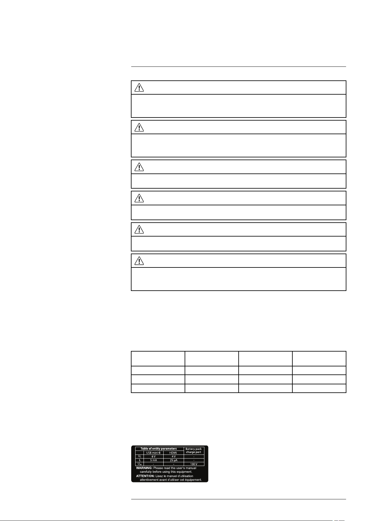
2.2.1 Table of entity parameters
The table shows the maximum input parameters for each port of the camera.
Table 2.1 Table of entity parameters
Parameter (see note) USB mini-B HDMI Battery pack charge
U
i
I
i
U
m
6 V 4 V
5 mA 25 µA
__ __
port
__
__
100 V
Ui= the maximum input voltage.
= the maximum input current.
I
i
= the maximum r.m.s. AC or DC voltage.
U
m
2.2.2 Battery warning label
The following warning label is affixed to the inside of the back cover:
#T810169; r. AN/42241/42268; en-US
8
Page 21
2
Safety information
2.2.3 Laser warning label
A laser warning label with the following information is affixed to the camera:
2.2.4 Laser rules and regulations
Wavelength: 635 nm. Maximum output power: 1 mW.
This product complies with 21 CFR 1040.10 and 1040.11 except for deviations pursuant
to Laser Notice No. 50, dated June 24, 2007.
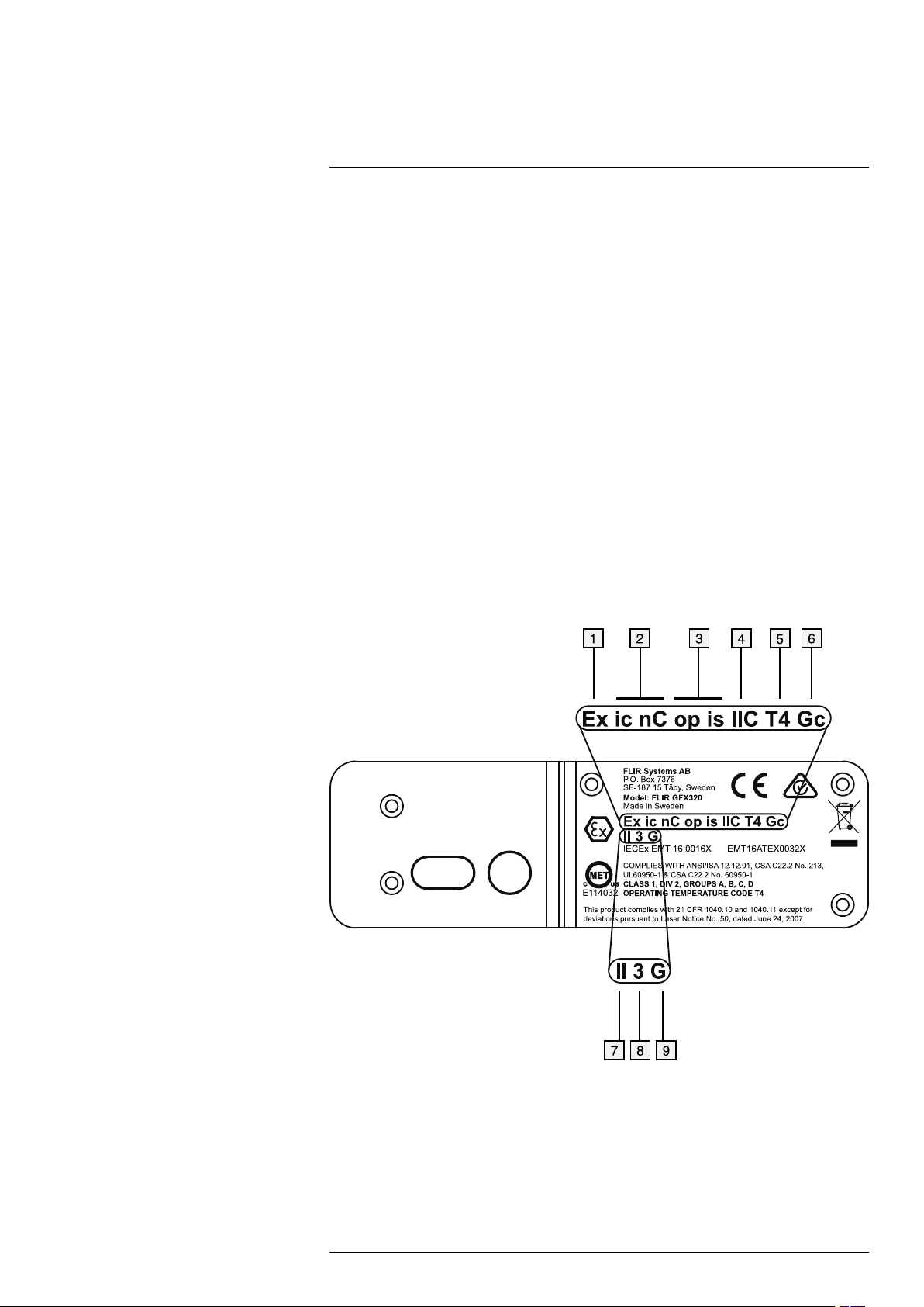
2.2.5 Compliance marking
2.2.5.1 Figure
A marking with the following information is laser-etched into the bottom of the camera
housing:
2.2.5.2 Explanation
1. Ex = Explosion protection.
2. Protection Type Codes: ic = intrinsic safe, nC = sealed device.
3. Inherently safe optical device.
4. Gas Group: IIC = acetylene, hydrogen, ethylene, and propane.
5. Temperature Classification Code: T4 = <135 ℃ (<275 ℉).
#T810169; r. AN/42241/42268; en-US
9
Page 22
2
Safety information
6. Equipment Protection Level (EPL): EPL is linked to the intended use and zones. Gc
is linked to Gas Group II, Zone 2 and constitutes minimum protection level of either n,
ic or pz.
7. Equipment Group: Group I = Mines, Group II = Other.
8. Equipment Category: 3 = Equipment suitable for use in Zone 2.
9. G = Gas.
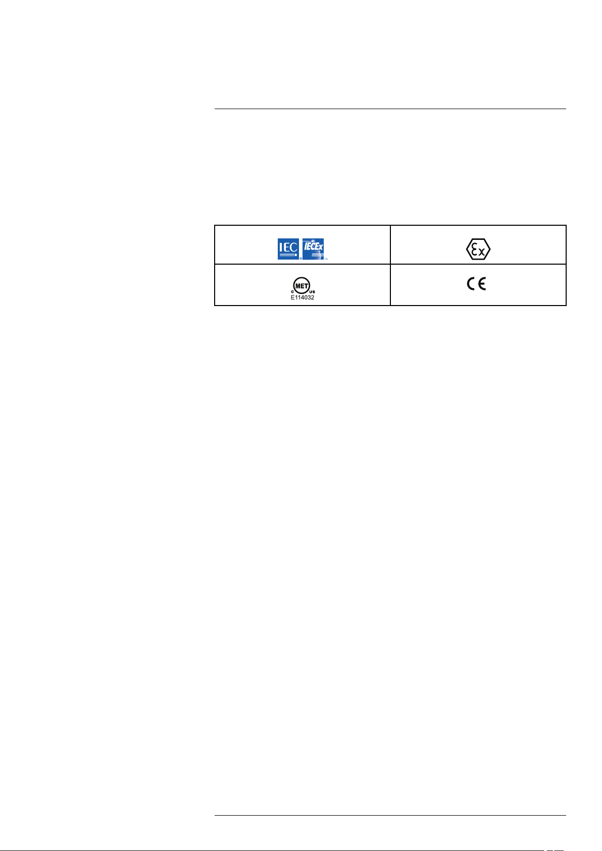
2.2.6 Applicable markings
2.2.7 Certifications
• ATEX/IECEx, Ex ic nC op is IIC T4 Gc
II 3 G
• ANSI/ISA-12.12.01-2013, Class I Division 2
• CSA 22.2 No. 213, Class I Division 2
2.2.8 Explosive (hazardous) environment
Standards related to explosive (hazardous) environment that the camera complies with:
• IEC 60079-0:2011
• IEC 60079-11:2011
• IEC 60079-15:2010 (partial)
• IEC 60079-28:2015
• BS EN 60079-0:2012
• BS EN 60079-11:2012
• BS EN 60079-15:2010
• BS EN 60079-28:2015
• ANSI/ISA-12.12.01-2013
• CSA 22.2 No. 213
• ATEX directive 2014/34/EU
2.2.9 Safety
Standards related to safety that the camera complies with:
• EN/UL/IEC 60950-1
#T810169; r. AN/42241/42268; en-US
10
Page 23

3
Notice to user
3.1 User-to-user forums
Exchange ideas, problems, and infrared solutions with fellow thermographers around the
world in our user-to-user forums. To go to the forums, visit:
http://forum.infraredtraining.com/
3.2 Calibration
Gas detection: no re-calibration recommendation. The ability to detect gases is not influenced by the calibration and will not degrade over time.
Temperature measurement: annual re-calibration recommended.
3.3 Accuracy
For very accurate results, we recommend that you wait 5 minutes after you have started
the camera before measuring a temperature.
For cameras where the detector is cooled by a mechanical cooler, this time period excludes the time it takes to cool down the detector.
3.4 Disposal of electronic waste
As with most electronic products, this equipment must be disposed of in an environmentally friendly way, and in accordance with existing regulations for electronic waste.
Please contact your FLIR Systems representative for more details.
3.5 Training
To read about infrared training, visit:
• http://www.infraredtraining.com
• http://www.irtraining.com
• http://www.irtraining.eu
3.6 Documentation updates
Our manuals are updated several times per year, and we also issue product-critical notifications of changes on a regular basis.
To access the latest manuals, translations of manuals, and notifications, go to the Download tab at:
http://support.flir.com
It only takes a few minutes to register online. In the download area you will also find the
latest releases of manuals for our other products, as well as manuals for our historical
and obsolete products.
#T810169; r. AN/42241/42268; en-US
11
Page 24

Notice to user3
3.7 Note about authoritative versions
The authoritative version of this publication is English. In the event of divergences due to
translation errors, the English text has precedence.
Any late changes are first implemented in English.
#T810169; r. AN/42241/42268; en-US
12
Page 25

4
Customer help
4.1 General
For customer help, visit:
http://support.flir.com
4.2 Submitting a question
To submit a question to the customer help team, you must be a registered user. It only
takes a few minutes to register online. If you only want to search the knowledgebase for
existing questions and answers, you do not need to be a registered user.
When you want to submit a question, make sure that you have the following information
to hand:
• The camera model
• The camera serial number
• The communication protocol, or method, between the camera and your device (for example, SD card reader, HDMI, Ethernet, USB, or FireWire)
• Device type (PC/Mac/iPhone/iPad/Android device, etc.)
• Version of any programs from FLIR Systems
#T810169; r. AN/42241/42268; en-US
13
Page 26

4
Customer help
• Full name, publication number, and revision number of the manual
4.3 Downloads
On the customer help site you can also download the following, when applicable for the
product:
• Firmware updates for your infrared camera.
• Program updates for your PC/Mac software.
• Freeware and evaluation versions of PC/Mac software.
• User documentation for current, obsolete, and historical products.
• Mechanical drawings (in *.dxf and *.pdf format).
• Cad data models (in *.stp format).
• Application stories.
• Technical datasheets.
• Product catalogs.
#T810169; r. AN/42241/42268; en-US
14
Page 27
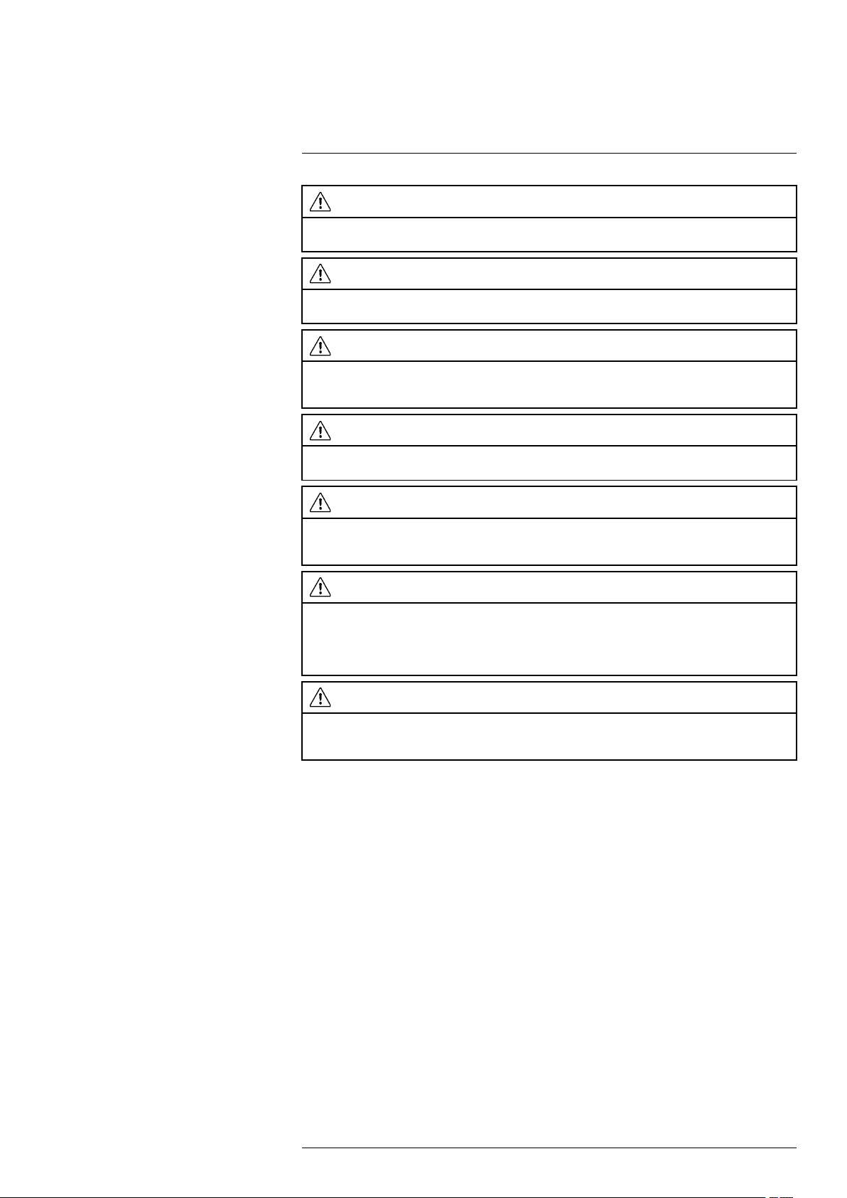
5
Conditions of Use for Ex Equipment
WARNING
Do not connect the camera to an external device while the camera is in a classified (hazardous) area.
An explosion can occur. This can cause injury or death to persons and damage to the equipment.
WARNING
Do not replace the memory card while the camera is in a classified (hazardous) area. An explosion can
occur. This can cause injury or death to persons and damage to the equipment.
WARNING
Do not open the cover for the connector and battery compartment while the camera is in a classified
(hazardous) area. An explosion can occur. This can cause injury or death to persons and damage to
the equipment.
WARNING
Do not replace the battery while the camera is in a classified (hazardous) area. An explosion can occur.
This can cause injury or death to persons and damage to the equipment.
WARNING
Only connect ATEX/IECEx-approved intrinsically safe equipment to the USB mini-B and HDMI ports. If
you do not obey this, an explosion can occur. This can cause injury or death to persons and damage to
the equipment.
CAUTION
You must only use this charger when you charge the battery: Manufactured by Ten Pao industrial Co.
Ltd., IECEE CB reference certificate No. JPTUV-035588-M1 (supplied by TUV Rheinland Japan Ltd.),
FLIR item part number 1196210 (FLIR sales part number T197692). FLIR Systems supplies the charger
and the battery packs with the camera equipment. If you do not obey this, damage to the equipment
can occur and the protection that the equipment gives can become unsatisfactory.
CAUTION
Only use the camera with a battery that has the item part number T199183 on it (that FLIR Systems
supplies). If you do not obey this, damage to the equipment can occur and the protection that the equipment gives can become unsatisfactory.
Note The encapsulation rating is only applicable when all the openings on the camera
are sealed with their correct covers, hatches, or caps. This includes the compartments
for data storage, batteries, and connectors.
#T810169; r. AN/42241/42268; en-US
15
Page 28

6
Important note about training and applications
6.1 General
Infrared inspection of gas leaks, furnaces, and high-temperature applications—including
infrared image and other data acquisition, analysis, diagnosis, prognosis, and reporting
—is a highly advanced skill. It requires professional knowledge of thermography and its
applications, and is, in some countries, subject to certification and legislation.
Consequently, we strongly recommend that you seek the necessary training before carrying out inspections. Please visit the following site for more information:
http://www.infraredtraining.com
#T810169; r. AN/42241/42268; en-US
16
Page 29

7
Important information about FLIR GFx3xx series service
• Service must only be performed by an authorized FLIR service department.
• Contact the service department before shipping the camera. Many problems can be
resolved on the phone—if so, the camera does not need to be shipped.
• If the camera has been subject to shock or vibration, it should be sent to an authorized
FLIR service department for control.
#T810169; r. AN/42241/42268; en-US
17
Page 30
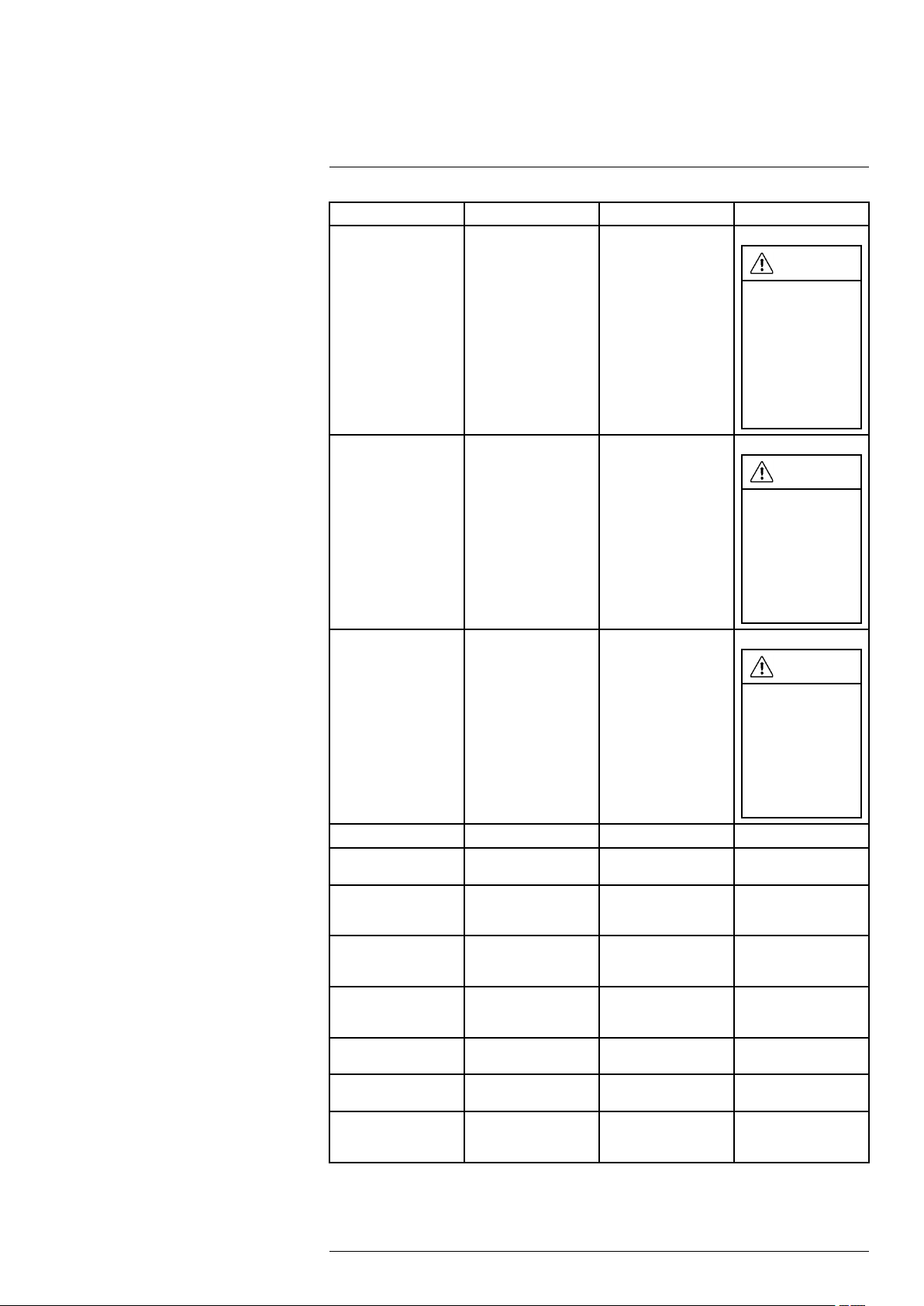
8
List of accessories and services
Product name Item part number Sales part number
Battery T199183 T199183ACC
WARNING
Do not replace this
item inside a classified (hazardous)
area. An explosion
can occur. An explosion can cause
death or injury to
persons and damage to the
equipment.
Battery charger, incl.
power supply with multi
plugs
Cigarette lighter adapter kit, 12 VDC, 1.2 m/
3.9 ft.
FLIR IR Camera Player N/A DSW-10000
FLIR Reporter Professional (license only)
FLIR ResearchIR Max
+ HSDR 4 (hardware
sec. dev.)
FLIR ResearchIR Max
+ HSDR 4 (printed license key)
FLIR ResearchIR Max
+ HSDR 4 Upgrade
(printed license key)
FLIR ResearchIR Max
4 (hardware sec. dev.)
FLIR ResearchIR Max
4 (printed license key)
FLIR ResearchIR Max
4 Upgrade (printed license key)
1196210 T197692
1910490 T198509
N/A T198586
N/A T198697
N/A
N/A
N/A T198696
N/A
N/A T199043
T199014
T199044
T199013
WARNING
Do not take this item
into a classified
(hazardous) area.
An explosion can
occur. An explosion
can cause death or
injury to persons
and damage to the
equipment.
WARNING
Do not take this item
into a classified
(hazardous) area.
An explosion can
occur. An explosion
can cause death or
injury to persons
and damage to the
equipment.
#T810169; r. AN/42241/42268; en-US
18
Page 31

8
List of accessories and services
Product name Item part number Sales part number
FLIR ResearchIR
Standard 4 (hardware
sec. dev.)
FLIR ResearchIR
Standard 4 (printed license key)
FLIR ResearchIR
Standard 4 Upgrade
(printed license key)
FLIR Tools N/A T198584
FLIR Tools+ (download
card incl. license key)
FLIR VideoReport N/A T198585
Hand strap T129728
Hard transport case T199466 T199466ACC
N/A T198731
N/A T199012
N/A
N/A
T199042
T198583
T129728ACC
HDMI to DVI cable 1.5mT910816 T910816ACC
HDMI to HDMI cable
1.5 m
T910815 T910815ACC
WARNING
Do not take this item
into a classified
(hazardous) area.
An explosion can
occur. An explosion
can cause death or
injury to persons
and damage to the
equipment.
WARNING
Do not take this item
into a classified
(hazardous) area.
An explosion can
occur. An explosion
can cause death or
injury to persons
and damage to the
equipment.
WARNING
Do not take this item
into a classified
(hazardous) area.
An explosion can
occur. An explosion
can cause death or
injury to persons
and damage to the
equipment.
Lens cap T129739 T129739ACC
Lens cap strap T129867
#T810169; r. AN/42241/42268; en-US
T129867ACC
19
Page 32

8
List of accessories and services
Product name Item part number Sales part number
Memory card SDHC 4
GB
T911650 T911650ACC
WARNING
Do not replace this
item inside a classified (hazardous)
area. An explosion
can occur. An explosion can cause
death or injury to
persons and damage to the
equipment.
Neck strap T129729
Power supply, incl. multi plugs
Screwdriver TX20
ThermoVision™ LabVIEW® Digital Toolkit
Ver. 3.3
ThermoVision™ System Developers Kit Ver.
2.6
USB cable Std A <->
Mini-B
T910814 T910814
T911309
N/A T198566
N/A
1910423 1910423
T129729ACC
WARNING
Do not take this item
into a classified
(hazardous) area.
An explosion can
occur. An explosion
can cause death or
injury to persons
and damage to the
equipment.
T911309ACC
WARNING
Do not take this item
into a classified
(hazardous) area.
An explosion can
occur. An explosion
can cause death or
injury to persons
and damage to the
equipment.
T198567
WARNING
Do not take this item
into a classified
(hazardous) area.
An explosion can
occur. An explosion
can cause death or
injury to persons
and damage to the
equipment.
Note FLIR Systems reserves the right to discontinue models, parts or accessories,
and other items, or to change specifications at any time without prior notice.
#T810169; r. AN/42241/42268; en-US
20
Page 33

9
Introduction
Thank you for choosing a FLIR GFx3xx series camera from FLIR Systems.
The FLIR GFx3xx series camera is an infrared camera for optical gas imaging (OGI) in
explosive atmospheres that visualizes and pinpoints leaks of methane and other volatile
organic compounds (VOCs), without the need to shut down the operation. The portable
camera also greatly improves operator safety, by detecting emissions at a safe distance,
and helps to protect the environment by tracing leaks of environmentally harmful gases.
The FLIR GFx3xx series camera is used in industrial settings such as oil refineries, natural gas processing plants, offshore platforms, chemical/petrochemical industries, and biogas and power generation plants.
Main features:
• Certified for use in an explosive atmosphere.
• Improved efficiency: The FLIR GFx320 reduces revenue loss by pinpointing gas
leaks quickly and efficiently, and from a distance. It also reduces the inspection time
by allowing a broad area to be scanned rapidly and without the need to interrupt the
industrial process. The FLIR GFx320 is also used for temperature measurement,
which makes it even more useful for predictive maintenance.
• Increased worker safety: OGI allows gas leaks to be detected in a non-contact
mode and from a safe distance. This reduces the risk of the user being exposed to invisible and potentially harmful or explosive chemicals. With a FLIR GFx320 gas imaging camera it is easy to scan areas of interest that are difficult to reach with
conventional methods. The camera is ergonomically designed, with a bright LCD and
tiltable viewfinder, which facilitates its use over a full working day.
• Protecting the environment: Several VOCs are dangerous to human health or
cause harm to the environment, and are usually governed by regulations. Even small
leaks can be detected and documented using the FLIR GFx320 camera.
#T810169; r. AN/42241/42268; en-US
21
Page 34

10
Example images
10.1 General
This section contains example images from various applications.
Note Gas leaks are easier to see in live image mode, which is the reason the leaks are
indicated with a red dot in the images below.
10.2 Images
#T810169; r. AN/42241/42268; en-US
22
Page 35

11
Quick start guide
11.1 Starting the camera for the first time
The first time you start the camera, you need to unlock the camera by entering a camera
unique code. The code is based on the serial number of the camera. To get the camera
unique code, you must log in with a FLIR Customer Support account and register the
camera. If you already have an existing FLIR Customer Support account, you can use
the same login credentials.
Follow this procedure:
1. Before operating the camera, you must read, understand, and follow the warnings,
cautions, and notes in sections , page and 5 Conditions of Use for Ex Equipment,
page 15.
2. Charge the battery for four hours, or until the green battery condition LED glows
continuously.
Note Do this at room temperature.
3. Put the battery into the battery compartment.
4. Insert a memory card into the card slot.
5. Close the cover and tighten the Torx T20 screw to 80 N cm.
6. Push the
Note When the camera is turned on, a mechanical cooler will begin cooling down
the infrared detector. The mechanical cooler has a sound that resembles a subdued
motor. This sound is normal. When the cooling procedure is completed, there is a
distinct change of the sound.
7. Use a computer or other device with internet access and go to the following website:
http://support.flir.com/unlock
This displays the following dialog:
button to turn on the camera. This displays the following dialog box:
#T810169; r. AN/42241/42268; en-US
23
Page 36

11
Quick start guide
8. To log in with your existing FLIR Customer Support account, do the following:
8.1. Enter your Username and Password.
8.2. Click Log In.
9. To create a new FLIR Customer Support account, do the following:
9.1. Click Create a New Account.
9.2. Enter the required information and click Create Account.
10. On the camera, push the joystick. This displays a dialog box. The serial number (S/
N) of the camera is displayed at the top of the screen.
Note The serial number is also available on a label in the battery compartment, see
section 14.8 Serial number, page 40.
#T810169; r. AN/42241/42268; en-US
24
Page 37

11
Quick start guide
11. On the computer, enter the serial number of the camera and click Validate.
12. When the serial number is validated, click Continue.
#T810169; r. AN/42241/42268; en-US
25
Page 38

11
Quick start guide
13. Enter the required information and click Register Product.
14. When the registration is completed, the four-digit code is displayed.
Note
• The code is also sent by e-mail to the address registered with your FLIR Customer
Support account.
• The code is also displayed in your FLIR Customer Support portal under My Stuff >
Products.
#T810169; r. AN/42241/42268; en-US
26
Page 39

11
Quick start guide
15. On the camera, do the following to enter the code:
• Move the joystick up/down to select a digit.
• Move the joystick left/right to navigate to the previous/next digit.
• When all digits have been entered, move the joystick right to select
joystick to confirm.
16. Depending on the entered code, one of the following will happen:
• If the entered code is correct,
box closes.
• If the entered code is incorrect,
log is zeroed and you can enter the code again.
17. The camera is now fully operational and, depending on the status of the cool-down
procedure, a progress bar or a video image is displayed.
18. To turn off the camera, push and hold the
displayed on the screen reaches the end.
Note The next time you turn on the camera, it will be fully operational from its start-up.
You do not have to go through the unlock procedure again.
is momentarily displayed. Then the unlock dialog
is momentarily displayed. Then the unlock dia-
button until the progress bar that is
. Push the
11.2 Detecting a gas leak
11.2.1 Procedure
Follow this procedure:
1. Before operating the camera, you must read, understand, and follow the warnings,
cautions, and notes in sections , page and 5 Conditions of Use for Ex Equipment,
page 15.
2. Charge the battery until the green battery condition LED glows continuously.
Note Do this at room temperature.
3. Put the battery into the battery compartment.
4. Insert a memory card into the card slot.
5. Close the cover and tighten the Torx T20 screw to 80 N cm.
6. Push the
down the infrared detector. A test image and a progress bar are displayed during
cool-down. When the cooling procedure is completed, a video image will be
displayed.
Note
• The mechanical cooler has a sound that resembles a subdued motor. This sound
is normal. When the cooling procedure is completed, there is a distinct change in
the sound.
• The cooling procedure typically takes 7 minutes. At high ambient temperatures
the cooling time may increase 30% or more.
button to turn on the camera. A mechanical cooler will begin cooling
#T810169; r. AN/42241/42268; en-US
27
Page 40

11
Quick start guide
7. Wait until the cooling procedure is completed. Then turn the mode wheel to
enter video mode.
8. Push the temperature range button, then do the following:
8.1. Move the joystick up/down to choose a suitable temperature range for your
object.
8.2. Push the temperature range button to confirm and leave the setup mode.
9. Aim the camera toward the target of interest.
10. Adjust the infrared camera focus by doing the following:
• For far focus, rotate the focus ring counter-clockwise (looking at the front of the
lens).
• For near focus, rotate the focus ring clockwise (looking at the front of the lens).
11. If there is a gas leak, and the gas is one of the gases that the camera can detect, you
will now see the leak on the screen. The leak will resemble a smoke plume emanating
from the point of the leak.
12. To start recording a video clip, push the
13. To stop recording a video clip, push the
dialog box.
14. To save the video clip, move the joystick to select
15. To move the video clip to a computer, do one of the following:
• Remove the memory card and insert it in a card reader connected to a computer.
• Connect a computer to the camera using a USB Mini-B cable.
Note To enable file transfer via the USB port, the USB mode setting must be set
button.
button again. This will display a preview
and push the joystick.
to
to Mass Storage Device. The setting is made in setup mode
tab. Select USB mode > Mass Storage Device.
16. Move the video clip from the card or camera using a drag-and-drop operation.
17. To turn off the camera, push and hold the
displayed on the screen reaches the end.
11.2.2 Related topics
• 18.1.1 Charging the battery using the power supply cable, page 51
• 18.1.2 Charging the battery using the stand-alone battery charger, page 51
• 18.2.1 Installing the battery, page 52
• 17 Connecting external devices, page 49
• 20.1 Laying out a measurement tool, page 63
• 19.1 Saving infrared images, page 60
• 22 Recording video clips, page 67
• 37 Detectable gases, page 106
button until the progress bar that is
in the Camera
11.3 Detecting a temperature
11.3.1 Procedure
Follow this procedure:
1. Before operating the camera, you must read, understand, and follow the warnings,
cautions, and notes in sections , page and 5 Conditions of Use for Ex Equipment,
page 15.
2. Charge the battery until the green battery condition LED glows continuously.
Note Do this at room temperature.
3. Put the battery into the battery compartment.
4. Insert a memory card into the card slot.
#T810169; r. AN/42241/42268; en-US
28
Page 41

11
Quick start guide
5. Close the cover and tighten the Torx T20 screw to 80 N cm.
6. Push the
button to turn on the camera. A mechanical cooler will begin cooling
down the infrared detector. A test image and a progress bar are displayed during
cool-down. When the cooling procedure is completed, a video image will be
displayed.
Note
• The mechanical cooler has a sound that resembles a subdued motor. This sound
is normal. When the cooling procedure is completed, there is a distinct change in
the sound.
• The cooling procedure typically takes 7 minutes. At high ambient temperatures
the cooling time may increase 30% or more.
7. Wait until the cooling procedure is completed. Then turn the mode wheel to
enter camera mode.
8. Push the temperature range button, then do the following:
8.1. Move the joystick up/down to choose a suitable temperature range for your
object.
8.2. Push the temperature range button to confirm and leave the setup mode.
9. Aim the camera toward the target of interest.
10. Adjust the infrared camera focus by doing the following:
• For far focus, rotate the focus ring counter-clockwise (looking at the front of the
lens).
• For near focus, rotate the focus ring clockwise (looking at the front of the lens).
11. Add a spotmeter by doing the following:
to
11.1. Push the
button to display a menu.
11.2. Move the joystick left/right to the Edit tab.
11.3. Move the joystick up/down to Add spot.
11.4. Push the joystick. A spotmeter is now displayed in the middle of the screen.
The spotmeter temperature is displayed in the result table in the top left corner
of the screen.
11.5. Move the joystick up/down/left/right to move the spotmeter on the screen.
11.6. Push the
12. To save an image directly, push and hold the
button to leave the setup mode.
button for more than one second.
13. To move the image to a computer, do one of the following:
• Remove the memory card and insert it in a card reader connected to a computer.
• Connect a computer to the camera using a USB Mini-B cable.
Note To enable file transfer via the USB port, the USB mode setting must be set
to Mass Storage Device. The setting is made in setup mode
in the Camera
tab. Select USB mode > Mass Storage Device.
14. Move the image from the card or camera using a drag-and-drop operation.
15. To turn off the camera, push and hold the
button until the progress bar that is
displayed on the screen reaches the end.
11.3.2 Related topics
• 18.1.1 Charging the battery using the power supply cable, page 51
• 18.1.2 Charging the battery using the stand-alone battery charger, page 51
• 18.2.1 Installing the battery, page 52
• 17 Connecting external devices, page 49
#T810169; r. AN/42241/42268; en-US
29
Page 42

11
Quick start guide
• 20.1 Laying out a measurement tool, page 63
• 19.1 Saving infrared images, page 60
#T810169; r. AN/42241/42268; en-US
30
Page 43

12
FLIR GFx3xx series general instrument check
The following general instrument check process ensures that the camera can detect the
intended gas compounds with the same sensitivity as when originally manufactured.
1. Make sure that the camera powers on.
2. Make sure that the camera completes the cool-down process and produces a live infrared image.
3. Make sure that the camera does not report any error messages on startup.
4. Make sure that the camera focuses properly.
5. Make sure that the camera is able to engage HSM mode.
#T810169; r. AN/42241/42268; en-US
31
Page 44

13
A note about ergonomics
13.1 General
To prevent overstrain injuries, it is important that you hold the camera ergonomically correct. This section gives advice and examples on how to hold the camera.
Note Please note the following:
• Always tilt the viewfinder to fit your work position.
• Always adjust the viewing angle of the display to fit your work position.
• Always adjust the camera grip to fit your work position.
• When you hold the camera, make sure that you support the camera housing with your
left hand too. This decreases the strain on your right hand.
13.2 Figure
#T810169; r. AN/42241/42268; en-US
32
Page 45

A note about ergonomics13
13.3 Related topics
• 18.5 Adjusting the viewing angle of the viewfinder, page 54
• 18.7 Adjusting the camera grip, page 55
• 18.9 Adjusting the viewing angle of the display, page 56
#T810169; r. AN/42241/42268; en-US
33
Page 46

14
Camera parts
14.1 View from the left
14.1.1 Figure
14.1.2 Explanation
1. Programmable button for one of the following functions:
• Change the zoom factor.
• Hide/show graphics.
• Change the polarity.
• Change the palette.
You program the button in setup mode
2. Temperature range button.
3. Mode wheel
• Camera mode: Save images.
• Video mode: Record video clips and video sequences.
• Archive mode: View saved images, video clips, and video sequences.
• Program mode: Set up periodical saving of images.
• Setup mode: Change the general settings.
4. Laser button.
5. Button to go between infrared mode and digital camera mode.
with the following modes:
in the Preferences tab.
#T810169; r. AN/42241/42268; en-US
34
Page 47

14
Camera parts
14.2 View from the right
14.2.1 Figure
14.2.2 Explanation
1. Camera handle.
2. Digital camera lamp. When you are in digital camera mode, you turn on the lamps by
pushing the joystick.
3. Digital video camera.
4. Laser pointer.
5. Digital camera lamp. When you are in digital camera mode, you turn on the lamps by
pushing the joystick.
6.
button (Preview/Save).
Function in camera mode:
• To preview an image before saving it, push and release the button.
• To save an image directly, push and hold the button for more than 1 second.
Function in video mode:
• To start recording a video clip, push the button.
• To stop recording a video clip, push the button again.
#T810169; r. AN/42241/42268; en-US
35
Page 48

14
Camera parts
7. A/M button (Auto/Manual).
Function:
• Push and release the button to change the image adjustment method between Au-
to, Manual, and HSM.
• Push and hold down the button for more than 1 second to perform a non-uniform-
ity correction (NUC).
Note
◦ Performing an NUC is typically not needed during normal operating procedures.
◦ The NUC should be performed against a uniform temperature scene. Other-
wise, the present image will create an artifact that will appear as a superimposed ghost image. If this occurs, restart the camera.
◦ When an NUC has been performed, an asterisk (*) is displayed in the result ta-
ble, indicating that the measurement may be affected. The asterisk disappears
when the camera is restarted.
◦ For more information, see section 42 About calibration, page 122.
8.
9. Hand strap.
10. Focus ring on the infrared lens.
11. Infrared lens.
button.
Function:
• When an image is in preview or archive mode, push the button left/right to adjust
the zoom.
• When an image is in live mode, the button has no function.
14.3 View from the rear
14.3.1 Figure
14.3.2 Explanation
1. Viewfinder.
2. Adjustment knob for the viewfinder’s diopter correction.
3. Cover for the connector and battery compartment. The cover is fastened with a Torx
screw (T20).
4. Power LED indicator.
#T810169; r. AN/42241/42268; en-US
36
Page 49

14
Camera parts
5. button (On/off).
Function:
• To turn on the camera, push and release the button.
• To turn off the camera, push and hold the button until the progress bar that is dis-
played on the screen reaches the end.
6. Joystick.
Function:
• To navigate in menus and dialog boxes, move the joystick up/down/left/right.
• To change values, move the joystick up/down/left/right.
• To select or confirm choices, push the joystick.
7.
button (Menu/Back).
14.4 View from the rear with open cover
14.4.1 Figure
14.4.2 Explanation
1. USB Mini-B cable (to connect the camera to a computer).
2. HDMI cable (for live video output).
3. Memory card slot.
4. Battery release button.
5. Battery.
WARNING
Do not open the cover for the connector and battery compartment while the camera is in a classified
(hazardous) area. An explosion can occur. This can cause injury or death to persons and damage to
the equipment.
CAUTION
Make sure that you do not use a torque value that is more than 80 Ncm on the Torx T20 screw. Damage
to the camera can occur if you do not obey this.
#T810169; r. AN/42241/42268; en-US
37
Page 50

14
Camera parts
CAUTION
Only use the camera with a battery that has the item part number T199183 on it (that FLIR Systems
supplies). If you do not obey this, damage to the equipment can occur and the protection that the equipment gives can become unsatisfactory.
14.5 Battery condition LED indicator
14.5.1 Figure
14.5.2 Explanation
This table gives an explanation of the battery condition LED indicator:
Type of signal Explanation
The LED is red and glows continuously. The battery needs to be charged..
The LED is green and flashes. The battery is being charged.
The LED is green and glows continuously. The battery is fully charged.
The LED is off. The power supply or the stand-alone battery
charger is disconnected from the battery.
14.6 Power LED indicator
14.6.1 Figure
14.6.2 Explanation
This table gives an explanation of the power LED indicator:
Type of signal Explanation
The LED is off. The camera is off.
The LED is green. The camera is on.
#T810169; r. AN/42241/42268; en-US
38
Page 51

14
Camera parts
14.7 Laser pointer
14.7.1 General
The camera has a laser pointer. When the laser pointer is on, you will see a laser dot approximately at the target.
14.7.2 Figure
This figure shows the difference in position between the laser pointer and the optical center of the infrared lens. The laser pointer and the optical axis are parallel.
WARNING
Do not look directly into the laser beam. The laser beam can cause eye irritation.
Note The symbol is displayed on the screen when the laser pointer is on.
14.7.3 Laser warning label
A laser warning label with the following information is affixed to the camera:
14.7.4 Laser rules and regulations
Wavelength: 635 nm. Maximum output power: 1 mW.
This product complies with 21 CFR 1040.10 and 1040.11 except for deviations pursuant
to Laser Notice No. 50, dated June 24, 2007.
#T810169; r. AN/42241/42268; en-US
39
Page 52

14
Camera parts
14.8 Serial number
14.8.1 General
The serial number of the camera is provided on a label in the battery compartment.
14.8.2 Figure
#T810169; r. AN/42241/42268; en-US
40
Page 53

15
Screen elements
15.1 Mode selector
Note To select the mode, turn the mode wheel on the left side of the camera.
15.1.1 Figure
15.1.2 Explanation
1. Camera mode.
2. Video mode: Record video clips (*.mp4) and video sequences (*.seq).
3. Archive mode: View saved images and video sequences.
4. Program mode: Set up periodical saving of images.
5. Setup mode: Change the general settings.
15.2 Result table and measurement tools
15.2.1 Figure
15.2.2 Explanation
1. Status bar.
2. Result table.
3. Area (measurement tool).
4. Spotmeter (measurement tool).
5. Line (measurement tool).
6. Adjustment method indicator.
7. Temperature scale.
15.3 Toolbox, indicators, and other objects
Note To display the menu, push the button.
#T810169; r. AN/42241/42268; en-US
41
Page 54

15
Screen elements
15.3.1 Figure
15.3.2 Explanation
1. Menu tab.
2. Mode indicator.
3. Menu tab name.
4. Menu item.
5. Status indicators:
• Time.
• Date.
• GPS indicator.
• USB indicator.
• Power indicator.
• Memory card indicator. The indicator shows the amount of free space on the
memory card. As a warning, the indicator will turn yellow and then red as the
amount of free space decreases.
#T810169; r. AN/42241/42268; en-US
42
Page 55

16
Achieving a good image
16.1 General
A good image depends on several different settings, although some settings affect the
image more than other.
These are the settings you need to experiment with:
• Adjusting the infrared camera focus.
• Adjusting the image, using Auto, Manual, or HSM (= High Sensitivity Mode).
• Selecting a suitable temperature range.
• Selecting a suitable color palette.
• Enabling or disabling histogram mode.
• Enabling or disabling inverted color palette.
• Changing object parameters.
This section explains how to change these settings.
16.2 Adjusting the infrared camera focus
Note Do not touch the lens surface when you adjust the infrared camera focus. If this
happens, clean the lens according to the instructions in 35.2 Infrared lens, page 104.
16.2.1 Figure
16.2.2 Procedure
Do one of the following:
• For far focus, rotate the focus ring counter-clockwise (looking at the front of the lens)
• For near focus, rotate the focus ring clock-wise (looking at the front of the lens)
16.3 Adjusting an image
16.3.1 General
Depending on camera model, an image can be adjusted in several different ways.
#T810169; r. AN/42241/42268; en-US
43
Page 56

Achieving a good image16
16.3.2 Explanation of the adjustment methods
Auto An adjustment method that will automatically adjust the image for best brightness
HSM HSM = High Sensitivity Mode.
Manual An adjustment method where you manually set the suitable temperature level and
and contrast.
An adjustment method that is specifically designed for gas detection applications.
Working in this mode, you can change the sensitivity to optimize the image quality.
temperature span according to the temperature of the objects in the scene.
For gas detection applications, this mode lets you center on the temperatures
around the background of the gas, so as to make the gas appear more clearly.
16.3.3 Procedure (Auto)
Follow this procedure to adjust an image using the Auto method:
1. Turn the mode wheel to
or .
2. Push the A/M button to select Auto. The image will now be continuously adjusted for
best image brightness and contrast.
16.3.4 Figure
This figure shows the HSM slider:
16.3.5 Procedure (HSM)
Follow this procedure to adjust an image using the HSM method:
1. Turn the mode wheel to
or .
2. Push the A/M button to select HSM. To change the sensitivity, move the joystick left/
right.
You will need to experiment with this setting until you get a clear image of a verified
gas leak.
16.3.6 Procedure (Manual)
Follow this procedure to adjust an image using the Manual method:
1. Turn the mode wheel to
or .
2. Push the A/M button to select Manual, then do one of the following:
• To change the temperature level, move the joystick up/down.
• To change the temperature span, move the joystick left/right.
16.4 Selecting a suitable temperature range
16.4.1 About temperature ranges
16.4.1.1 General
The camera has three different types of ranges. Within each type of range, there are several subranges. You must choose a suitable range for your object.
#T810169; r. AN/42241/42268; en-US
44
Page 57

Achieving a good image16
16.4.1.2 Types of temperature ranges
Type
1
2 Temperature range +10°C to +50°C (+50°F
3 Temperature span
Name
Characteristic temperature range
Example Explanation
–40°C to +350°C (–40°
F to +662°F)
to +122°F)
+23.8°C to +25.9°C
(+74.8°F to +78.6°F)
All temperatures the
camera can register.
This range is the total
sum of the temperature
ranges (type no. 2
below).
The span of temperatures that the camera
can register with the
current settings.
This type of range is a
subrange to type no. 1
above.
The range of temperatures that the camera
registers when aimed
at a particular scene
with a particular temperature range set.
16.4.2 Understanding the temperature scale
16.4.2.1 Figure
16.4.2.2 Explanation
1. Currently set minimum temperature in the temperature span (= range of type 3 in the
table 16.4.1.2 Types of temperature ranges, page 45).
2. Currently set maximum temperature in the temperature span (= range of type 3 in the
table 16.4.1.2 Types of temperature ranges, page 45).
3. Currently set maximum temperature in the range that the camera can register with
the current settings (= range of type 2 in the table 16.4.1.2 Types of temperature
ranges, page 45).
4. Indicator that represents the temperature range (= range of type 2 in the table
16.4.1.2 Types of temperature ranges, page 45).
5. Indicator that represents the temperature span (= range of type 3 in the table
16.4.1.2 Types of temperature ranges, page 45).
6. Currently set minimum temperature in the range that the camera can register with the
current settings (= range of type 2 in the table 16.4.1.2 Types of temperature ranges,
page 45).
#T810169; r. AN/42241/42268; en-US
45
Page 58

Achieving a good image16
16.4.3 Changing the temperature range
16.4.3.1 Procedure
Follow this procedure to change the temperature range:
1. Do one of the following:
• Push the temperature range button on the left side of the camera.
• Push the
2. Move the joystick up/down to choose a suitable temperature range for your object.
3. Push the temperature range button to confirm and leave the setup mode.
button, then select Adjust temp. range.
16.5 Selecting a suitable color palette
16.5.1 Procedure
1. Turn the mode wheel to
2. Push the
3. Move the joystick left/right to go to the Image tab.
4. Move the joystick up/down to go to select Color palette.
5. Push the joystick to enable the list of palettes.
6. Move the joystick up/down to select a new palette.
7. Push the joystick.
8. Push the
button to display a menu.
button to leave the setup mode.
or .
16.6 Enabling or disabling histogram mode
16.6.1 General
Histogram mode is an image-displaying method that evenly distributes the color information over the existing temperatures of the image.
16.6.2 Procedure
1. Turn the mode wheel to
2. Push the
3. Move the joystick left/right to go to the Image tab.
4. Move the joystick up/down to go to select Histogram.
5. Push the joystick to enable/disable the setting.
6. Push the
button to display a menu.
button to leave the setup mode.
or .
16.7 Enabling or disabling inverted color
palette
16.7.1 Procedure
1. Turn the mode wheel to
2. Push the
3. Move the joystick left/right to go to the Image tab.
#T810169; r. AN/42241/42268; en-US
button to display a menu.
or .
46
Page 59

Achieving a good image16
4. Move the joystick up/down to go to select Invert palette.
5. Push the joystick to enable/disable the setting.
6. Push the
button to leave the setup mode.
16.8 Changing object parameters
16.8.1 General
For accurate measurements, you must set the object parameters. You can do this locally
or globally. This procedure describes how to change the object parameters globally.
16.8.2 Types of parameters
The camera can use these object parameters:
• Emissivity, i.e., how much radiation an object emits, compared to the radiation of a
theoretical reference object of the same temperature (called a “blackbody”). The opposite of emissivity is reflectivity. The emissivity determines how much of the radiation
originates from the object as opposed to being reflected by it.
• Reflected apparent temperature, which is used when compensating for the radiation
from the surroundings reflected by the object into the camera. This property of the object is called reflectivity.
• Object distance, i.e., the distance between the camera and the object of interest.
• Atmospheric temperature, i.e., the temperature of the air between the camera and the
object of interest.
• Relative humidity, i.e., the relative humidity of the air between the camera and the ob-
ject of interest.
• External optics temperature, i.e., the temperature of any protective windows etc. that
are set up between the camera and the object of interest. If no protective window or
protective shield is used, this value is irrelevant.
• External optics transmission, i.e., the optical transmission of any protective windows,
etc. that are set up between the camera and the object of interest.
16.8.3 Recommended values
If you are unsure about the values, the following values are recommended:
Emissivity 0.95
Distance 1.0 m (3.3 ft.)
Reflected apparent temperature
Relative humidity 50%
Atmospheric
temperature
+20°C (+69°F)
+20°C (+69°F)
16.8.4 Procedure
Follow this procedure to change the object parameters globally:
1. Turn the mode wheel to
2. Push the
button to display a menu.
or .
3. Move the joystick left/right to go to the Edit tab.
4. Move the joystick up/down to select Object parameters.
5. Push the joystick to display a dialog box.
6. Move the joystick up/down to select the parameter you want to change, then push
the joystick.
7. Move the joystick up/down to change the value, then push the joystick.
#T810169; r. AN/42241/42268; en-US
47
Page 60

Achieving a good image16
8. Push the
button to confirm and leave the setup mode.
Note
• Of the seven parameters above, emissivity and reflected apparent temperature are
the two most important to set correctly in the camera.
• To change object parameters locally, first select a measurement tool in the toolbox,
then select Use local parameters. Change the local parameters by selecting Edit local
parameters, then edit them in the same way as for global object parameters.
16.8.5 Related topics
• For in-depth information about parameters, and how to correctly set emissivity and re-
flected apparent temperature, see 41 Thermographic measurement techniques.
#T810169; r. AN/42241/42268; en-US
48
Page 61

17
Connecting external devices
17.1 General
You can connect the following external devices to the camera:
• A video monitor or projector, connected using an HDMI cable.
• A computer, to move images and other files to and from the camera.
• An SD memory card.
• An SDHC memory card.
The connectors for the external devices are protected by the connector and battery compartment cover. The cover is fastened with a Torx screw (T20).
Note Before operating the camera, you must read, understand, and follow the warnings, cautions, and notes in sections , page and 5 Conditions of Use for Ex Equipment,
page 15.
17.2 Figure
17.3 Explanation
1. To connect a computer to the camera to move images and files to and from the camera, use a USB Mini-B cable and this connector.
2. To play live video from the camera on an external video monitor using the HDMI protocol (High Definition Multimedia Interface), use an HDMI cable and this connector.
3. To insert a memory card, use this card slot.
Note The connectors on the card must face down when inserting the card.
17.4 Formatting memory cards
For best performance, memory cards should be formatted to the FAT (FAT16) file system.
Using FAT32-formatted memory cards may result in inferior performance. To format a
memory card to FAT (FAT16), follow this procedure:
1. Insert the memory card into a card reader that is connected to a computer running
Microsoft Windows.
#T810169; r. AN/42241/42268; en-US
49
Page 62

17
Connecting external devices
2. In Windows Explorer, select My Computer and right-click the memory card.
3. Select Format.
4. Under File system, select FAT.
5. Click Start.
Note
• SDHC memory cards that are 4 GB or larger can only be formatted to the FAT32 file
system.
#T810169; r. AN/42241/42268; en-US
50
Page 63

18
Handling the camera
18.1 Charging the camera battery
WARNING
Make sure that you install the socket-outlet near the equipment and that it is easy to get access to.
Note
• You must charge the battery for 4 hours before starting the camera for the first time.
After that, you must charge the battery whenever a warning message for low battery
power is displayed on the screen.
• The battery has a battery condition LED indicator. When the green LED glows contin-
uously, the battery is fully charged.
• Charge the battery at room temperature.
18.1.1 Charging the battery using the power supply cable
18.1.1.1 Procedure
Follow this procedure to charge the battery using the power supply cable:
1. Before operating the camera, you must read, understand, and follow the warnings,
cautions, and notes in sections , page and 5 Conditions of Use for Ex Equipment,
page 15.
2. Remove the battery from the camera.
3. Connect the power supply cable plug to the connector on the battery. The connector
is protected by a rubber cover.
4. Connect the power supply wall plug to a mains supply.
5. When the green LED of the battery condition indicator glows continuously, disconnect the power supply cable.
18.1.1.2 Related topics
• For information about the battery condition LED indicator, see 14.5 Battery condition
LED indicator, page 38.
• For information on how to install and remove the battery, see 18.2.1 Installing the bat-
tery, page 52 and 18.2.2 Removing the battery, page 52.
18.1.2 Charging the battery using the stand-alone battery charger
18.1.2.1 Procedure
Follow this procedure to charge the battery using the stand-alone battery charger:
1. Before operating the camera, you must read, understand, and follow the warnings,
cautions, and notes in sections , page and 5 Conditions of Use for Ex Equipment,
page 15.
2. Put the battery in the stand-alone battery charger.
3. Connect the power supply cable plug to the connector on the stand-alone battery
charger.
4. Connect the power supply wall plug to a mains supply.
5. When the green LED of the battery condition indicator glows continuously, disconnect the power supply cable.
18.1.2.2 Related topics
• For information about the battery condition LED indicator, see 14.5 Battery condition
LED indicator, page 38.
• For information on how to install and remove the battery, see 18.2.1 Installing the bat-
tery, page 52 and 18.2.2 Removing the battery, page 52.
#T810169; r. AN/42241/42268; en-US
51
Page 64

Handling the camera18
18.2 Installing and removing the camera
battery
18.2.1 Installing the battery
Note Use a clean, dry cloth to remove any water or moisture on the battery before you
install it.
18.2.1.1 Procedure
Follow this procedure:
1. Before operating the camera, you must read, understand, and follow the warnings,
cautions, and notes in sections , page and 5 Conditions of Use for Ex Equipment,
page 15.
2. Unscrew the Torx T20 screw and open the battery compartment cover.
3. Push the battery into the battery compartment. The battery makes a click when it
locks in place.
4. Close the cover and tighten the Torx T20 screw to 80 N cm.
18.2.2 Removing the battery
18.2.2.1 Procedure
Follow this procedure:
1. Before operating the camera, you must read, understand, and follow the warnings,
cautions, and notes in sections , page and 5 Conditions of Use for Ex Equipment,
page 15.
2. Turn off the camera.
#T810169; r. AN/42241/42268; en-US
52
Page 65

Handling the camera18
3. Unscrew the Torx T20 screw and open the battery compartment cover.
4. Push the release button for the battery.
5. Pull out the battery from the battery compartment.
18.3 Turning on the camera
18.3.1 Procedure
To turn on the camera, push and release the
Note
• The mechanical cooler has a sound that resembles a subdued motor. This sound is
normal. When the cooling procedure is completed, there is a distinct change in the
sound.
• The cooling procedure typically takes 7 minutes. At high ambient temperatures the
cooling time may increase 30% or more.
button.
18.4 Turning off the camera
18.4.1 Procedure
To turn off the camera, push and hold the
played on the screen reaches the end.
button until the progress bar that is dis-
#T810169; r. AN/42241/42268; en-US
53
Page 66

Handling the camera18
18.5 Adjusting the viewing angle of the
viewfinder
18.5.1 General
To make your working position as comfortable as possible, you can adjust the viewing
angle of the viewfinder.
18.5.2 Figure
18.5.3 Procedure
To adjust the viewfinder, tilt the viewfinder up or down.
18.6 Adjusting the viewfinder’s dioptric
correction
18.6.1 General
The viewfinder’s dioptric correction can be adjusted for your eyesight.
18.6.2 Figure
#T810169; r. AN/42241/42268; en-US
54
Page 67

Handling the camera18
18.6.3 Procedure
To adjust the viewfinder’s dioptric correction, look at the displayed text or graphics on the
screen and rotate the adjustment knob clockwise or counter-clockwise for best
sharpness.
Note
• Maximum dioptric correction: +2
• Minimum dioptric correction: –2
18.7 Adjusting the camera grip
18.7.1 General
To make your working position as comfortable as possible, you can adjust the angle of
the camera grip.
18.7.2 Figure
18.7.3 Procedure
To adjust the camera grip, rotate the camera grip clockwise or counter-clockwise.
18.8 Opening the display
18.8.1 Figure
#T810169; r. AN/42241/42268; en-US
55
Page 68

Handling the camera18
18.9 Adjusting the viewing angle of the display
18.9.1 General
To make your working position as comfortable as possible, you can adjust the viewing
angle of the display.
18.9.2 Figure
18.9.3 Procedure
To adjust the viewing angle of the display, rotate the display clockwise or counterclockwise.
18.10 Adjusting the infrared camera focus
Note Do not touch the lens surface when you adjust the infrared camera focus. If this
happens, clean the lens according to the instructions in 35.2 Infrared lens, page 104.
18.10.1 Figure
#T810169; r. AN/42241/42268; en-US
56
Page 69

Handling the camera18
18.10.2 Procedure
Do one of the following:
• For far focus, rotate the focus ring counter-clockwise (looking at the front of the lens)
• For near focus, rotate the focus ring clock-wise (looking at the front of the lens)
18.11 Using the zoom function
18.11.1 General
You can zoom in on infrared images in preview or archive mode. This enables you to view
details in an image.
18.11.2 Procedure
Do one of the following:
• To zoom into or out of a live image, choose Zoom on the second tab in the menu sys-
tem, then use the joystick.
• To zoom into or out of an image in preview or archive mode, push the
left/right.
button
#T810169; r. AN/42241/42268; en-US
57
Page 70

Handling the camera18
18.12 Operating the laser pointer
18.12.1 Figure
18.12.2 Procedure
Follow this procedure to operate the laser pointer:
1. To turn on the laser pointer, push and hold the laser button.
2. To turn off the laser pointer, release the laser button.
WARNING
Do not look directly into the laser beam. The laser beam can cause eye irritation.
Note The symbol is displayed on the screen when the laser pointer is on.
18.13 Laser warning label
A laser warning label with the following information is affixed to the camera:
18.14 Laser rules and regulations
Wavelength: 635 nm. Maximum output power: 1 mW.
This product complies with 21 CFR 1040.10 and 1040.11 except for deviations pursuant
to Laser Notice No. 50, dated June 24, 2007.
#T810169; r. AN/42241/42268; en-US
58
Page 71

Handling the camera18
18.15 Assigning functions to the
programmable button
18.15.1 General
The camera has a programmable button. You can assign one of the following functions
to the programmable button:
• Change the zoom factor.
• Hide/show graphics.
• Change the polarity.
• Change the palette.
18.15.2 Procedure
Follow this procedure:
1. Turn the mode wheel to
2. Select the Preferences tab and push the joystick.
3. Select Programmable button and push the joystick.
4. Select one of the functions and push the joystick.
5. To leave the setup mode, turn the mode wheel and select another mode.
to enter setup mode.
#T810169; r. AN/42241/42268; en-US
59
Page 72

19
Working with views and images
19.1 Saving infrared images
19.1.1 General
You can save one or more images to an SD Memory Card.
19.1.2 Image capacity
The approximate number of images that can be saved on an SD Memory Card is 2,000
per GB.
19.1.3 Saving an infrared image directly to an SD Memory Card
19.1.3.1 General
You can save an image directly to an SD Memory Card, without previewing the image
first.
19.1.3.2 Procedure
Follow this procedure to save an image directly to an SD Memory Card:
1. Turn the mode wheel to
2. To save an image without previewing, push and hold the
one second.
19.1.4 Previewing and saving an infrared image to an SD Memory Card
19.1.4.1 General
You can preview an image before you save it to an SD Memory Card. This lets you do
one or more of the following tasks before you save the image:
• Edit measurements.
• Adjust the image.
• Add a digital photo.
• Delete an image.
19.1.4.2 Procedure
Follow this procedure to preview and save an image to an SD Memory Card:
1. Turn the mode wheel to
2. Push and release the
3. You can now do one or more of the following tasks before you save the image. Move
the joystick to go to a task and push the joystick to select the task.
• Select
to edit measurement tools.
.
button for more than
.
button. This will display a preview dialog box.
• Select
• Select
lamps by pushing the joystick. Push the
• Select
• Select
#T810169; r. AN/42241/42268; en-US
to adjust the image.
to add a digital photo to the image. You turn on the digital camera
to delete the image.
to save the image.
button to take a digital photo.
60
Page 73

Working with views and images19
19.2 Opening an image
19.2.1 General
When you save an image, you store the image on an SD Memory Card. To display the
image again, you can open it from the SD Memory Card.
19.2.2 Procedure
Follow this procedure to open an image:
1. Turn the mode wheel to
view or an image at full size.
2. In the archive overview, you can do the following:
• Move the joystick up/down/left/right to select the image you want to view.
• Push the joystick. This displays the selected image at full size.
3. When an image is displayed at full size, you can do the following:
• Push the joystick or the
delete the image. This displays a menu.
• Move the joystick left/right to view the previous/next image.
• Move the joystick up to return to the archive overview.
4. To leave the archive mode, turn the mode wheel and select another mode.
to enter archive mode. This displays the archive over-
button to edit the measurements, adjust the image, or
19.3 Changing settings related to image
presentation
19.3.1 General
In live mode, you can enable/disable a variety of settings relating to image presentation.
These settings include:
• Zoom, i.e., zoom into or out of images.
• Hide/show graphics, i.e. hide or show the on-screen graphics.
• Change the color palette, i.e. the colors that are used to display the temperatures in
the infrared image.
• Invert polarity, i.e. change the image polarity from white = hot to black = hot.
• Histogram equalization, i.e., an image-displaying method that evenly distributes the
color information over the existing temperatures of the image.
Note In preview and archive mode, you can do the following related to image
presentation:
• Push the
• Depending on the function you have assigned to the programmable button, you can
hide/show graphics, change the polarity, or change the palette. For more information,
see section 18.15 Assigning functions to the programmable button, page 59.
19.3.2 Procedure
1. Turn the mode wheel to
2. Push the
3. Move the joystick left/right to go to the Image tab.
4. Move the joystick up/down to go to select the setting that you want to change.
5. Push the joystick to enable/disable the setting.
(If you select Zoom you can change the zoom factor by moving the joystick up/down.)
#T810169; r. AN/42241/42268; en-US
button left/right to zoom into or out of the image.
or .
button to display a menu.
61
Page 74

Working with views and images19
6. Push the
button to leave the setup mode.
19.4 Editing a saved image
19.4.1 General
You can edit a saved image. You can do one or more of the following tasks:
• Edit measurements.
• Adjust the image.
• Delete the image.
19.4.2 Procedure
Follow this procedure:
1. Open the image at full size in the archive. For more information, see section 19.2
Opening an image, page 61.
2. Push the joystick or the
3. You can now do one or more of the following tasks. Move the joystick to go to a task
and push the joystick to select the task.
• Select
• Select
Note You can only adjust an image that has been saved in Auto or Manual mode.
An image saved in HSM mode cannot be adjusted. For more information, see section 16.3 Adjusting an image, page 43.
to edit measurement tools.
to adjust the image.
. This displays a menu.
• Select
• Select
to delete the image.
to save any changes and exit edit mode.
19.5 Deleting a file
19.5.1 Procedure
Follow this procedure to delete an image file, a video clip, or a video sequence:
1. Turn the mode wheel to
view or an image at full size.
2. If an image is displayed at full size, move the joystick up to go to the archive overview.
3. Move the joystick up/down/left/right to select the image you want to delete.
4. Push the
5. Move the joystick up/down to select one of the following:
• Delete
• Delete all
6. Push the joystick.
7. Confirm the deletion and push the joystick.
button to display a menu.
to enter archive mode. This displays the archive over-
#T810169; r. AN/42241/42268; en-US
62
Page 75

20
Working with measurement tools
20.1 Laying out a measurement tool
20.1.1 General
To measure a temperature, you use one or several measurement tools, such as a spotmeter, a box, etc.
20.1.2 Procedure
Follow this procedure to lay out measurement tool:
1. Turn the mode wheel to
2. Push the
3. Move the joystick left/right to go to the Edit tab.
4. Move the joystick up/down to select the measurement tool you want to lay out.
5. Push the joystick. The measurement tool has now been created on the screen.
button to display a menu.
or .
20.2 Moving or resizing a measurement tool
20.2.1 General
You can move and resize a measurement tool.
20.2.2 Procedure
Note This procedure assumes that you have previously laid out a measurement tool on
the screen.
Follow this procedure to move or resize a measurement tool:
1. Turn the mode wheel to
2. Push the
3. Move the joystick left/right to go to the Edit tab.
4. Move the joystick up/down to select the measurement tool that you want to move or
resize.
5. Push the joystick to display a menu.
6. Move the joystick up/down to select Move or Resize.
7. Move the joystick up/down and left/right to move or resize the measurement tool.
8. Push the joystick to confirm.
button to display a menu.
or .
9. Push the
button to leave the setup mode.
20.3 Creating & setting up a difference
calculation
20.3.1 General
A difference calculation returns the difference between the values of two known measurement results, or between the value of a measurement result and the reference
temperature.
20.3.2 Procedure
Note This procedure assumes that you have previously laid out at least two measure-
ment tools on the screen.
#T810169; r. AN/42241/42268; en-US
63
Page 76

Working with measurement tools20
Follow this procedure to create and set up a difference calculation:
1. Turn the mode wheel to
2. Push the
3. Move the joystick left/right to go to the Edit tab.
4. Move the joystick up/down to select Add difference.
5. Push the joystick to display a dialog box.
6. Do the following and push the joystick to confirm each choice:
6.1. To select the first function in the difference calculation, select Function 1 and
6.2. (Not applicable if there is only one measurement tool.) To select the ID of the
6.3. (Not applicable to spotmeter and reference temperature.) To select the result
7. Do the following and push the joystick to confirm each choice:
7.1. To select the second function in the difference calculation, select Function 2
7.2. (Not applicable if there is only one measurement tool.) To select the ID of the
7.3. (Not applicable to spotmeter.) To select the result type of the measurement
button to display a menu.
push the joystick. Move the joystick up/down to select the measurement tool
you want to use for this function.
measurement tool, select Id and push the joystick. Move the joystick up/down
to select the ID.
type of the measurement tool (Min., Max., Avg.), select Type and push the joystick. Move the joystick up/down to select the result type of the measurement
tool.
and push the joystick. Move the joystick up/down to select the measurement
tool you want to use for this function.
measurement tool, select Id and push the joystick. Move the joystick up/down
to select the ID.
tool (Min., Max., Avg.), select Type and push the joystick. Move the joystick
up/down to select the result type of the measurement tool.
or .
8. Push the
button to confirm and leave the setup mode.
20.4 Changing object parameters
20.4.1 General
For accurate measurements, you must set the object parameters. You can do this locally
or globally. This procedure describes how to change the object parameters globally.
20.4.2 Types of parameters
The camera can use these object parameters:
• Emissivity, i.e., how much radiation an object emits, compared to the radiation of a
theoretical reference object of the same temperature (called a “blackbody”). The opposite of emissivity is reflectivity. The emissivity determines how much of the radiation
originates from the object as opposed to being reflected by it.
• Reflected apparent temperature, which is used when compensating for the radiation
from the surroundings reflected by the object into the camera. This property of the object is called reflectivity.
• Object distance, i.e., the distance between the camera and the object of interest.
• Atmospheric temperature, i.e., the temperature of the air between the camera and the
object of interest.
• Relative humidity, i.e., the relative humidity of the air between the camera and the ob-
ject of interest.
• External optics temperature, i.e., the temperature of any protective windows etc. that
are set up between the camera and the object of interest. If no protective window or
protective shield is used, this value is irrelevant.
#T810169; r. AN/42241/42268; en-US
64
Page 77

Working with measurement tools20
• External optics transmission, i.e., the optical transmission of any protective windows,
etc. that are set up between the camera and the object of interest.
20.4.3 Recommended values
If you are unsure about the values, the following values are recommended:
Emissivity 0.95
Distance 1.0 m (3.3 ft.)
Reflected apparent temperature
Relative humidity 50%
Atmospheric
temperature
+20°C (+69°F)
+20°C (+69°F)
20.4.4 Procedure
Follow this procedure to change the object parameters globally:
1. Turn the mode wheel to
2. Push the
button to display a menu.
or .
3. Move the joystick left/right to go to the Edit tab.
4. Move the joystick up/down to select Object parameters.
5. Push the joystick to display a dialog box.
6. Move the joystick up/down to select the parameter you want to change, then push
the joystick.
7. Move the joystick up/down to change the value, then push the joystick.
8. Push the
button to confirm and leave the setup mode.
Note
• Of the seven parameters above, emissivity and reflected apparent temperature are
the two most important to set correctly in the camera.
• To change object parameters locally, first select a measurement tool in the toolbox,
then select Use local parameters. Change the local parameters by selecting Edit local
parameters, then edit them in the same way as for global object parameters.
20.4.5 Related topics
• For in-depth information about parameters, and how to correctly set emissivity and re-
flected apparent temperature, see 41 Thermographic measurement techniques.
#T810169; r. AN/42241/42268; en-US
65
Page 78

21
Programming the camera
21.1 General
You can program the camera to save images periodically.
21.2 Procedure
Follow this procedure to make the camera save images periodically:
1. Turn the mode wheel to
2. Move the joystick up/down to select Setup.
3. Push the joystick. This will display the following dialog box:
4. Push the joystick.
5. Use the joystick to set the following:
• The type of images to save (IR image, Digital photo, IR and digital).
• The time period between which the camera will save an image (hours, minutes,
seconds).
• The stop condition (timer, counter, manual)
• The timer or counter settings, if you selected one of these as stop condition.
. This will display the following dialog box:
6. Push the
7. Move the joystick up/down to select Start.
8. Push the joystick to start the periodic saving.
#T810169; r. AN/42241/42268; en-US
button.
66
Page 79

22
Recording video clips
22.1 General
You can record infrared or visual video clips (*.mp4), as well as radiometric video sequence files (*.seq). In this mode, the camera can be regarded as an ordinary digital video camera. The video clips can be edited and played back in FLIR VideoReport.
*.seq video clips can also be handled and edited in FLIR Reporter.
22.2 Procedure
1. Turn the mode wheel to .
2. Push the
the screen displays the elapsed recording time.
3. To stop the recording, push the
4. You can now do one or more of the following tasks before you save the video clip.
• Select
lamps by pushing the joystick. Push the
• Select
• Select
back counter to the beginning of the video clip.
• Select
• Select
• Select
button. The recording has now begun. A timer in the top right corner of
button. This will display a preview dialog box.
to add a digital photo to the video clip. You turn on the digital camera
button to take a digital photo.
to play the video clip.
to stop the playback of the video clip. This will also reset the play-
to pause/resume the playback of the video clip.
to discard the video clip.
to keep the video clip.
#T810169; r. AN/42241/42268; en-US
67
Page 80

23
Changing settings
23.1 General
You can change a variety of settings for the camera:
• Regional settings, such as language, date, time, etc.
• Camera settings, such as digital camera color, display intensity, etc.
• Preferences, such as user-configurable buttons, image overlay information, text size,
etc. Here you can also set the camera to stamp the temperature scale into the image.
• Camera information, such as serial number, part number, used and free memory, etc.
No changes are possible here, only presentation of information.
23.2 Procedure
Follow this procedure to change settings:
1. Turn the mode wheel to
2. Move the joystick left/right to go to the desired tab.
3. Move the joystick up/down to select the desired menu item.
4. Push the joystick. This will highlight a setting (or display a submenu, depending on
the context).
5. Move the joystick up/down to change the setting.
6. Push the joystick to confirm the choice.
7. (To close a submenu, push the
8. To leave the setup mode, turn the mode wheel and select another mode.
to enter setup mode.
button.)
#T810169; r. AN/42241/42268; en-US
68
Page 81

24
Technical data
Table of contents
24.1 Online field-of-view calculator........................................................... 69
24.2 Note about technical data................................................................. 69
24.3 Note about authoritative versions...................................................... 69
24.4 FLIR GFx320 14.5° fixed lens............................................................. 70
24.5 FLIR GFx320 24° fixed lens ............................................................... 75
24.1 Online field-of-view calculator
Please visit http://support.flir.com and click the photo of the camera series for field-of-
view tables for all lens–camera combinations.
24.2 Note about technical data
FLIR Systems reserves the right to change specifications at any time without prior notice.
Please check http://support.flir.com for latest changes.
24.3 Note about authoritative versions
The authoritative version of this publication is English. In the event of divergences due to
translation errors, the English text has precedence.
Any late changes are first implemented in English.
#T810169; r. AN/42241/42268; en-US
69
Page 82

Technical data24
24.4 FLIR GFx320 14.5° fixed lens
P/N: 74902-0101
Rev.: 41315
General description
The FLIR GFx320 is an infrared camera for optical gas imaging (OGI) in explosive atmospheres that
visualizes and pinpoints leaks of methane and other volatile organic compounds (VOCs), without the
need to shut down the operation. The portable camera also greatly improves operator safety, by detecting emissions at a safe distance, and helps to protect the environment by tracing leaks of environmentally harmful gases.
The FLIR GFx320 is used in industrial settings such as oil refineries, natural gas processing plants, offshore platforms, chemical/petrochemical industries, and biogas and power generation plants.
Benefits:
• Certified for use in an explosive atmosphere.
• Improved efficiency: The FLIR GFx320 reduces revenue loss by pinpointing gas leaks quickly and
efficiently, and from a distance. It also reduces the inspection time by allowing a broad area to be
scanned rapidly and without the need to interrupt the industrial process. The FLIR GFx320 is also
used for temperature measurement, which makes it even more useful for predictive maintenance.
• Increased worker safety: OGI allows gas leaks to be detected in a non-contact mode and from a
safe distance. This reduces the risk of the user being exposed to invisible and potentially harmful or
explosive chemicals. With a FLIR GFx320 gas imaging camera it is easy to scan areas of interest
that are difficult to reach with conventional methods. The camera is ergonomically designed, with a
bright LCD and tiltable viewfinder, which facilitates its use over a full working day.
• Protecting the environment: Several VOCs are dangerous to human health or cause harm to the environment, and are usually governed by regulations. Even small leaks can be detected and documented using the FLIR GFx320 camera.
Detects the following gases: benzene, ethanol, ethylbenzene, heptane, hexane, isoprene, methanol,
MEK, MIBK, octane, pentane, 1-pentene, toluene, xylene, butane, ethane, methane, propane, ethylene,
propylene.
Imaging and optical data
IR resolution 320 × 240 pixels
Thermal sensitivity/NETD <15 mK @ +30°C (+86°F)
Field of view (FOV)
Minimum focus distance 0.5 m (1.64 ft.)
Focal length 38 mm (1.49 in.)
F-number 1.5
Focus Manual focus
Zoom 1–8× continuous, digital zoom
Digital image enhancement
Detector data
Detector type Focal plane array (FPA), cooled InSb
Spectral range
Detector pitch 30 µm
Sensor cooling Stirling Microcooler (FLIR MC-3)
Detects following gases Benzene, Ethanol, Ethylbenzene, Heptane, Hex-
Electronics and data rate
Full frame rate 60 Hz
14.5° × 10.8°
Noise reduction filter, high sensitivity mode (HSM)
3.2–3.4 µm
ane, Isoprene, Methanol, MEK, MIBK, Octane,
Pentane, 1-Pentene, Toluene, Xylene, Butane,
Ethane, Methane, Propane, Ethylene, Propylene
#T810169; r. AN/42241/42268; en-US
70
Page 83

Technical data24
Image presentation
Display Built-in widescreen, 4.3 in. LCD, 800 × 480 pixels
Viewfinder Built-in, tiltable OLED, 800 × 480 pixels
Automatic image adjustment Continuous/manual; linear or histogram based
Manual image adjustment
Image presentation modes
Image modes IR image, visual image, high sensitivity mode
Measurement
Temperature range
Accuracy
Measurement analysis
Spotmeter
Area 5 boxes with max./min./average
Profile 1 live line (horizontal or vertical)
Difference temperature Delta temperature between measurement func-
Reference temperature Manually set or captured from any measurement
Emissivity correction Variable from 0.01 to 1.0 or selected from editable
Reflected apparent temperature correction Automatic, based on input of reflected
Measurement corrections Reflected temperature, distance, atmospheric
Level/span
(HSM)
–20°C to +350°C (–4°F to +662°F)
±1°C (±1.8°F) for temperature range (0°C, to
+100°C, +32°F to +212°F) or ±2% of reading for
temperature range (>+100°C, >+212°F)
10
tions or reference temperature
function
materials list
temperature
transmission, humidity, external optics
Set-up
Menu commands
Color palettes
Set-up commands
Storage of images
Storage media Removable SD or SDHC memory card
Image storage capacity 2000 images (JPEG) with post process capability
Image storage mode
• Level, span
• Auto adjust continuous/manual/semiautomatic
• Zoom
• Palette
• Start/stop recording
• Store image
• Playback/recall image
• Iron
• Gray
• Rainbow
• Arctic
• Lava
• Rainbow HC
1 programmable button, overlay recording mode,
local adaptation of units, language, date and time
formats
per GB on memory card
• IR/visual images
• Visual image can automatically be associated
with corresponding IR image
#T810169; r. AN/42241/42268; en-US
71
Page 84

Technical data24
Storage of images
Periodic image storage Every 10 seconds up to 24 hours
File formats Standard JPEG, 14 bit measurement data
Geographic Information System
GPS Location data automatically added to every image
Video recording in camera
Radiometric IR video recording *.seq video clips to memory card (7.5 and 15 Hz).
Non-radiometric IR video recording
Visual video recording
included
from built-in GPS
• MPEG4 (up to 60 minutes/clip) to memory
card.
• Visual image can automatically be associated
with corresponding recording of non-radiometric IR video.
MPEG4 (25 minutes/clip) to memory card
Video streaming
Radiometric IR video streaming Full dynamic to PC using USB cable. PC software
Non-radiometric IR video streaming
Digital camera
Built-in digital camera 3.2 Mpixels, auto focus, and two video lamps
Laser pointer
Laser Activated by dedicated button
Laser classification Class 2
Laser type Semiconductor AlGaInP diode laser, 1 mW, 635
USB
USB USB Mini-B: Data transfer to and from PC
USB, standard USB Mini-B: 2.0 high speed
Composite video
Video out Digital video output (image)
Power system
Battery type Rechargeable Li ion battery
Battery voltage 7.2 V
Battery capacity 4.4 Ah
Battery operating time
Charging system In camera (AC adapter or 12 V from a vehicle) or
Charging time
Charging temperature 0°C to +45°C (+32°F to +113°F), except for the
capable of displaying the video stream include the
following:
• FLIR IR Camera Player
• FLIR ResearchIR
• FLIR Tools
RTP/MPEG4
nm (red)
> 3 hours at 25°C (+68°F) and typical use
2-bay charger
2.5 h to 95% capacity, charging status indicated
by LED's
Korean market: +10°C to +45°C (+50°F to +113°
F)
#T810169; r. AN/42241/42268; en-US
72
Page 85

Technical data24
Power system
External power operation
DC operation 8 to 15.3 V DC, polarity protected (proprietary
Power 8.5 W typically
Start-up time Typically 7 min. @ 25°C (+77°F)
Environmental data
Operating temperature range –20°C to +50°C (–4°F to +122°F)
Ambient temperature range (certification range for
explosive atmospheres)
Storage temperature range –30°C to +60°C (–22°F to +140°F)
Humidity (operating and storage) IEC 68-2-30/24 h 95% relative humidity +25°C to
Explosive (hazardous) environment
Low voltage
RoHS 2011/65/EU
WEEE
EMC
Encapsulation
Shock 25 g (IEC 60068-2-27)
Vibration 2 g (IEC 60068-2-6)
Safety EN/UL/IEC 60950-1
AC adapter 90–260 VAC, 50/60 Hz or 12 V from a
vehicle (cable with standard plug, optional)
protected)
–20°C to +40°C (–4°F to +104°F)
+40°C (+77°F to +104°F) (2 cycles)
• IEC 60079-0:2011
• IEC 60079-11:2011
• IEC 60079-15:2010 (partial)
• IEC 60079-28:2015
• BS EN 60079-0:2012
• BS EN 60079-11:2012
• BS EN 60079-15:2010
• BS EN 60079-28:2015
• ANSI/ISA-12.12.01-2013
• CSA 22.2 No. 213
• ATEX directive 2014/34/EU
73/23/EEC
2012/19/EU
• The Electromagnetic Compatibility (EMC) Directive 2014/30/EU
• EN61000-6-4 (Emission)
• EN61000-6-2 (Immunity)
• FCC 47 CFR Part 15 class A (Emission)
• EN 61 000-4-8, L5
IP 54 (IEC 60529)
Physical data
Camera weight, incl. battery 2.80 kg (6.18 lbs.)
Camera weight, excl. battery 2.59 kg (5.71 lbs.)
Battery weight 0.21 kg (0.47 lbs.)
Camera size (L × W × H) 245 × 166 × 164 mm (9.6 × 6.5 × 6.4 in.)
Battery size (L × W × H) 141 × 43 × 28 mm (5.5 × 1.7 × 1.1 in.)
Battery charger size (L × W × H) 158 × 122 × 25 mm (6.2 × 4.8 × 1.0 in.)
Tripod mounting
Housing material Aluminum, magnesium, silicone
#T810169; r. AN/42241/42268; en-US
UNC ¼"-20
73
Page 86

Technical data24
Certifications
Compliance
Shipping information
Packaging, type
List of contents
EAN-13 7332558012574
UPC-12
• ATEX/IECEx, Ex ic nC op is IIC T4 Gc
II 3 G
• ANSI/ISA-12.12.01-2013, Class I Division 2
• CSA 22.2 No. 213, Class I Division 2
Cardboard box
• Battery charger
• Battery, 2 ea.
• Hand strap
• Hard transport case
• HDMI-DVI cable
• HDMI-HDMI cable
• Infrared camera with lens
• Lens cap (mounted on lens)
• Lens cap strap
• Memory card
• Neck strap
• Power supply, incl. multi-plugs
• Printed documentation
• Screwdriver TX20
• USB cable
845188013721
Course organization
ITC
ITC Trainers and Licensed Trainers
• T197692; Battery charger, incl. power supply with multi plugs
• T910814; Power supply, incl. multi plugs
• T911650ACC; Memory card SD Card 8 GB
• 1910423; USB cable Std A <-> Mini-B
• T198509; Cigarette lighter adapter kit, 12 VDC, 1.2 m/3.9 ft.
• T910815ACC; HDMI to HDMI cable 1.5 m
• T910816ACC; HDMI to DVI cable 1.5 m
• T129739ACC; Lens cap
• T129867ACC; Lens cap strap
• T129729ACC; Neck strap
• T129728ACC; Hand strap
• T911309ACC; Screwdriver TX20
#T810169; r. AN/42241/42268; en-US
74
Page 87

Technical data24
24.5 FLIR GFx320 24° fixed lens
P/N: 74902-0102
Rev.: 41314
General description
The FLIR GFx320 is an infrared camera for optical gas imaging (OGI) in explosive atmospheres that
visualizes and pinpoints leaks of methane and other volatile organic compounds (VOCs), without the
need to shut down the operation. The portable camera also greatly improves operator safety, by detecting emissions at a safe distance, and helps to protect the environment by tracing leaks of environmentally harmful gases.
The FLIR GFx320 is used in industrial settings such as oil refineries, natural gas processing plants, offshore platforms, chemical/petrochemical industries, and biogas and power generation plants.
Benefits:
• Certified for use in an explosive atmosphere.
• Improved efficiency: The FLIR GFx320 reduces revenue loss by pinpointing gas leaks quickly and
efficiently, and from a distance. It also reduces the inspection time by allowing a broad area to be
scanned rapidly and without the need to interrupt the industrial process. The FLIR GFx320 is also
used for temperature measurement, which makes it even more useful for predictive maintenance.
• Increased worker safety: OGI allows gas leaks to be detected in a non-contact mode and from a
safe distance. This reduces the risk of the user being exposed to invisible and potentially harmful or
explosive chemicals. With a FLIR GFx320 gas imaging camera it is easy to scan areas of interest
that are difficult to reach with conventional methods. The camera is ergonomically designed, with a
bright LCD and tiltable viewfinder, which facilitates its use over a full working day.
• Protecting the environment: Several VOCs are dangerous to human health or cause harm to the environment, and are usually governed by regulations. Even small leaks can be detected and documented using the FLIR GFx320 camera.
Detects the following gases: benzene, ethanol, ethylbenzene, heptane, hexane, isoprene, methanol,
MEK, MIBK, octane, pentane, 1-pentene, toluene, xylene, butane, ethane, methane, propane, ethylene,
propylene.
Imaging and optical data
IR resolution 320 × 240 pixels
Thermal sensitivity/NETD <15 mK @ +30°C (+86°F)
Field of view (FOV)
Minimum focus distance 0.3 m (1.0 ft.)
Focal length 23 mm (0.89 in.)
F-number 1.5
Focus Manual focus
Zoom 1–8× continuous, digital zoom
Digital image enhancement Noise reduction filter, high sensitivity mode (HSM)
Detector data
Detector type Focal plane array (FPA), cooled InSb
Spectral range
Detector pitch 30 µm
Sensor cooling Stirling Microcooler (FLIR MC-3)
Detects following gases Benzene, Ethanol, Ethylbenzene, Heptane, Hex-
Electronics and data rate
Full frame rate 60 Hz
24° × 18°
3.2–3.4 µm
ane, Isoprene, Methanol, MEK, MIBK, Octane,
Pentane, 1-Pentene, Toluene, Xylene, Butane,
Ethane, Methane, Propane, Ethylene, Propylene
#T810169; r. AN/42241/42268; en-US
75
Page 88

Technical data24
Image presentation
Display Built-in widescreen, 4.3 in. LCD, 800 × 480 pixels
Viewfinder Built-in, tiltable OLED, 800 × 480 pixels
Automatic image adjustment Continuous/manual; linear or histogram based
Manual image adjustment
Image presentation modes
Image modes IR image, visual image, high sensitivity mode
Measurement
Temperature range
Accuracy
Measurement analysis
Spotmeter
Area 5 boxes with max./min./average
Profile 1 live line (horizontal or vertical)
Difference temperature Delta temperature between measurement func-
Reference temperature Manually set or captured from any measurement
Emissivity correction Variable from 0.01 to 1.0 or selected from editable
Reflected apparent temperature correction Automatic, based on input of reflected
Measurement corrections Reflected temperature, distance, atmospheric
Level/span
(HSM)
–20°C to +350°C (–4°F to +662°F)
±1°C (±1.8°F) for temperature range (0°C, to
+100°C, +32°F to +212°F) or ±2% of reading for
temperature range (>+100°C, >+212°F)
10
tions or reference temperature
function
materials list
temperature
transmission, humidity, external optics
Set-up
Menu commands
Color palettes
Set-up commands
Storage of images
Storage media Removable SD or SDHC memory card
Image storage capacity 2000 images (JPEG) with post process capability
Image storage mode
• Level, span
• Auto adjust continuous/manual/semiautomatic
• Zoom
• Palette
• Start/stop recording
• Store image
• Playback/recall image
• Iron
• Gray
• Rainbow
• Arctic
• Lava
• Rainbow HC
1 programmable button, overlay recording mode,
local adaptation of units, language, date and time
formats
per GB on memory card
• IR/visual images
• Visual image can automatically be associated
with corresponding IR image
#T810169; r. AN/42241/42268; en-US
76
Page 89

Technical data24
Storage of images
Periodic image storage Every 10 seconds up to 24 hours
File formats Standard JPEG, 14 bit measurement data
Geographic Information System
GPS Location data automatically added to every image
Video recording in camera
Radiometric IR video recording *.seq video clips to memory card (7.5 and 15 Hz).
Non-radiometric IR video recording
Visual video recording
included
from built-in GPS
• MPEG4 (up to 60 minutes/clip) to memory
card.
• Visual image can automatically be associated
with corresponding recording of non-radiometric IR video.
MPEG4 (25 minutes/clip) to memory card
Video streaming
Radiometric IR video streaming Full dynamic to PC using USB cable. PC software
Non-radiometric IR video streaming
Digital camera
Built-in digital camera 3.2 Mpixels, auto focus, and two video lamps
Laser pointer
Laser Activated by dedicated button
Laser classification Class 2
Laser type Semiconductor AlGaInP diode laser, 1 mW, 635
USB
USB USB Mini-B: Data transfer to and from PC
USB, standard USB Mini-B: 2.0 high speed
Composite video
Video out Digital video output (image)
Power system
Battery type Rechargeable Li ion battery
Battery voltage 7.2 V
Battery capacity 4.4 Ah
Battery operating time
Charging system In camera (AC adapter or 12 V from a vehicle) or
Charging time
Charging temperature 0°C to +45°C (+32°F to +113°F), except for the
capable of displaying the video stream include the
following:
• FLIR IR Camera Player
• FLIR ResearchIR
• FLIR Tools
RTP/MPEG4
nm (red)
> 3 hours at 25°C (+68°F) and typical use
2-bay charger
2.5 h to 95% capacity, charging status indicated
by LED's
Korean market: +10°C to +45°C (+50°F to +113°
F)
#T810169; r. AN/42241/42268; en-US
77
Page 90

Technical data24
Power system
External power operation
DC operation 8 to 15.3 V DC, polarity protected (proprietary
Power 8.5 W typically
Start-up time Typically 7 min. @ 25°C (+77°F)
Environmental data
Operating temperature range –20°C to +50°C (–4°F to +122°F)
Ambient temperature range (certification range for
explosive atmospheres)
Storage temperature range –30°C to +60°C (–22°F to +140°F)
Humidity (operating and storage) IEC 68-2-30/24 h 95% relative humidity +25°C to
Explosive (hazardous) environment
Low voltage
RoHS 2011/65/EU
WEEE
EMC
Encapsulation
Shock 25 g (IEC 60068-2-27)
Vibration 2 g (IEC 60068-2-6)
Safety EN/UL/IEC 60950-1
AC adapter 90–260 VAC, 50/60 Hz or 12 V from a
vehicle (cable with standard plug, optional)
protected)
–20°C to +40°C (–4°F to +104°F)
+40°C (+77°F to +104°F) (2 cycles)
• IEC 60079-0:2011
• IEC 60079-11:2011
• IEC 60079-15:2010 (partial)
• IEC 60079-28:2015
• BS EN 60079-0:2012
• BS EN 60079-11:2012
• BS EN 60079-15:2010
• BS EN 60079-28:2015
• ANSI/ISA-12.12.01-2013
• CSA 22.2 No. 213
• ATEX directive 2014/34/EU
73/23/EEC
2012/19/EU
• The Electromagnetic Compatibility (EMC) Directive 2014/30/EU
• EN61000-6-4 (Emission)
• EN61000-6-2 (Immunity)
• FCC 47 CFR Part 15 class A (Emission)
• EN 61 000-4-8, L5
IP 54 (IEC 60529)
Physical data
Camera weight, incl. battery 2.72 kg (6.00 lbs.)
Camera weight, excl. battery 2.50 kg (5.51 lbs.)
Battery weight 0.21 kg (0.47 lbs.)
Camera size (L × W × H) 245 × 166 × 164 mm (9.6 × 6.5 × 6.4 in.)
Battery size (L × W × H) 141 × 43 × 28 mm (5.5 × 1.7 × 1.1 in.)
Battery charger size (L × W × H) 158 × 122 × 25 mm (6.2 × 4.8 × 1.0 in.)
Tripod mounting
Housing material Aluminum, magnesium, silicone
#T810169; r. AN/42241/42268; en-US
UNC ¼"-20
78
Page 91

Technical data24
Certifications
Compliance
Shipping information
Packaging, type
List of contents
EAN-13 7332558012567
UPC-12
• ATEX/IECEx, Ex ic nC op is IIC T4 Gc
II 3 G
• ANSI/ISA-12.12.01-2013, Class I Division 2
• CSA 22.2 No. 213, Class I Division 2
Cardboard box
• Battery charger
• Battery, 2 ea.
• Hand strap
• Hard transport case
• HDMI-DVI cable
• HDMI-HDMI cable
• Infrared camera with lens
• Lens cap (mounted on lens)
• Lens cap strap
• Memory card
• Neck strap
• Power supply, incl. multi-plugs
• Printed documentation
• Screwdriver TX20
• USB cable
845188013714
Course organization
ITC
ITC Trainers and Licensed Trainers
• T197692; Battery charger, incl. power supply with multi plugs
• T910814; Power supply, incl. multi plugs
• T911650ACC; Memory card SD Card 8 GB
• 1910423; USB cable Std A <-> Mini-B
• T198509; Cigarette lighter adapter kit, 12 VDC, 1.2 m/3.9 ft.
• T910815ACC; HDMI to HDMI cable 1.5 m
• T910816ACC; HDMI to DVI cable 1.5 m
• T129739ACC; Lens cap
• T129867ACC; Lens cap strap
• T129729ACC; Neck strap
• T129728ACC; Hand strap
• T911309ACC; Screwdriver TX20
#T810169; r. AN/42241/42268; en-US
79
Page 92

25
Mechanical drawings
[See next page]
#T810169; r. AN/42241/42268; en-US
80
Page 93

6,52in
165,5mm
10,92in
277,2mm
3,7in
94mm
2,36in
60mm
2,05in
52mm
2,8in
71mm
6,45in
163,9mm
9,66in
245,3mm
7,62in
193,5mm
11,92in
302,7mm
3,07in
R78mm
GFx320 24 deg
6,54in
166mm
1,86in
47,2mm
4,17in
105,8mm
0,22in
5,5mm
UNC 1/4"-20
Sheet
Drawing No.
Size
Check
Drawn by
Denomination
A3
1(2)
T129664
GFx320 basic dimensions
ANLI
2016-04-13
R&D Thermography
Modified
1 2 3 4 5 6 7 8 9 10
A
B
C
D
E
F
G
H
1 32 54
C
F
B
D
G
E
A
6
Size
A
1:3
Scale
© 2012, FLIR Systems, Inc. All rights reserved worldwide. No part of this drawing may be reproduced, stored in a retrieval system, or transmitted in any form, or by any means, electronic, mechanical, photocopying, recording, or otherwise,
without written permission from FLIR Systems, Inc. Specifications subject to change without further notice. Dimensional data is based on nominal values. Products may be subject to regional market considerations. License procedures may apply.
Product may be subject to US Export Regulations. Please refer to exportquestions@flir.com with any questions. Diversion contrary to US law is prohibited.
-
-
Page 94

6,52in
165,5mm
10,92in
277,2mm
3,7in
94mm
2,36in
60mm
2,05in
52mm
2,8in
71mm
6,45in
163,9mm
9,66in
245,3mm
7,62in
193,5mm
11,92in
302,7mm
3,07in
R78mm
GFx320 14,5 deg
6,54in
166mm
1,86in
47,2mm
4,17in
105,8mm
0,22in
5,5mm
UNC 1/4"-20
Sheet
Drawing No.
Size
Check
Drawn by
Denomination
A3
2(2)
T129664
GFx320 basic dimensions
ANLI
2016-04-13
R&D Thermography
Modified
1 2 3 4 5 6 7 8 9 10
A
B
C
D
E
F
G
H
1 32 54
C
F
B
D
G
E
A
6
Size
A
1:3
Scale
© 2012, FLIR Systems, Inc. All rights reserved worldwide. No part of this drawing may be reproduced, stored in a retrieval system, or transmitted in any form, or by any means, electronic, mechanical, photocopying, recording, or otherwise,
without written permission from FLIR Systems, Inc. Specifications subject to change without further notice. Dimensional data is based on nominal values. Products may be subject to regional market considerations. License procedures may apply.
Product may be subject to US Export Regulations. Please refer to exportquestions@flir.com with any questions. Diversion contrary to US law is prohibited.
-
-
Page 95

26
EU Declaration of conformity
[See next page]
#T810169; r. AN/42241/42268; en-US
83
Page 96

Page 97

27
MET Compliance Data Report (truncated)
[See next page]
#T810169; r. AN/42241/42268; en-US
85
Page 98

TEST STANDARD IEC/EN 60079-15
SAFJ TDS-103A Blank Test Data Sheets 6-17-2013 Page 1 of 10
Issued by: Department Manager or designee
Clause
Test
22.5.2
Before Seal Test Voltage Test (Component)
22.5.1
Conditioning (Component)
22.5.3.2
Seal Component Test (Component) Method 3
22.5.3.3
After Seal Test Dielectric Test (Component)
N/A
Critical Drawings
Page 99

TEST STANDARD IEC/EN 60079-15
SAFJ TDS-103A Blank Test Data Sheets 6-17-2013 Page 2 of 10
Issued by: Department Manager or designee
Compliance
Test Data Report
Manufacturer/Applicant:
FLIR Systems AB
Antennvägen 6, 187 66 Täby, Sweden
/Element Materials Technology
Century Court Tolpits Lane Walford, Herts, UK WD18 9RS
Product description:
IDCA Component within the FLIR George Camera, Model GFx320.
Note: Testing will be with respect to EN/IEC 60079-15:2010 clause 22.5 as this testing is more onerous
than ANSI/ISA 12.12.01:2012 and CSA/CAN C22.2 No. 213 (reaffirmed 2013) requirements.
CEIT# 17072-1: SB4293v2 (500-0525-00-07)
CEIT# 17072-2: SB4310v2 (500-0525-00-07)
CEIT# 17072-3: SB4275v2 (500-0525-00-07)
MET Laboratories, Inc.
13501 McCallen Pass
Austin, Texas 78753
(512) 287-2500
© Copyright 2016
The data in this report shall not be reproduced except in full, without the express written consent of MET Laboratories, Inc. Continued
compliance or engineering data may not be used, interpreted, or presented as proof of compliance
Page 100

28
IEC/IECEE/Intertek Test Report (truncated)
[See next page]
#T810169; r. AN/42241/42268; en-US
88
 Loading...