

Page 1
User’s manual
FLIR GF3xx series
Page 2

Page 3

User’s manual
FLIR GF3xx series
#T559157; r. AH/45951/45951; en-US
iii
Page 4

Page 5

Table of contents
1 Disclaimers ........................... ................................. ............................1
1.1 Legal disclaimer ......................................................................... 1
1.2 U.S. Government Regulations........................................................1
1.3 Level 1 statement........................................................................1
1.4 Copyright ..................................................................................2
1.5 Quality assurance .......................................................................2
1.6 Patents..................................................................................... 2
1.7 EULA Terms ..............................................................................2
1.8 EULA Terms ..............................................................................3
2 Safety information ......................... ................................. .....................5
3 Notice to user ............................ ............................... .. ...................... 10
3.1 User-to-user forums .................................................................. 10
3.2 Calibration............................................................................... 10
3.3 Accuracy ................................................................................ 10
3.4 Disposal of electronic waste........................................................ 10
3.5 Training .................................................................................. 10
3.6 Documentation updates ............................................................. 11
3.7 Note about authoritative versions.................................................. 11
4 Customer help ........................... ............................... .. ...................... 12
4.1 General .................................................................................. 12
4.2 Submitting a question ................................................................ 12
4.3 Downloads .............................................................................. 13
5 Important note about training and applications............. .. ...................... 14
5.1 General .................................................................................. 14
6 List of accessories and services ........ .. ............................... ................ 15
7 Introduction................... .. ............................... ................................. . 17
7.1 FLIR GF300............................................................................. 17
7.1.1 Optical gas imaging of methane and other volatile organic
7.1.2 Benefits ....................................................................... 17
7.2 FLIR GF304............................................................................. 17
7.2.1 Optical gas imaging of refrigerant gases.............................. 17
7.2.2 Benefits ....................................................................... 17
7.3 FLIR GF306............................................................................. 18
7.3.1 Optical gas imaging especially of SF6 and ammonia .............. 18
7.3.2 Benefits ....................................................................... 18
7.4 FLIR GF309............................................................................. 18
7.4.1 IR camera for furnace and high temperature
7.4.2 Benefits ....................................................................... 19
7.5 FLIR GF320............................................................................. 19
7.5.1 Optical gas imaging of methane and other volatile organic
7.5.2 Benefits ....................................................................... 19
7.6 FLIR GF335............................................................................. 20
7.6.1 Benefits ....................................................................... 20
7.7 FLIR GF343............................................................................. 20
7.7.1 The new FLIR GF343 is an optical gas camera for
7.7.2 Main applications ........................................................... 20
compounds (VOCs) ........................................................ 17
inspection..................................................................... 18
compounds (VOCs) ........................................................ 19
visualizing carbon dioxide (CO
......................................... 20
2
#T559157; r. AH/45951/45951; en-US
v
Page 6

Table of contents
7.8 FLIR GF346............................................................................. 21
7.8.1 Optical gas imaging especially of carbon monoxide (CO)
and other harmful gases .................................................. 21
7.8.2 Benefits ....................................................................... 21
8 Example images ...... .. ............................... ............................... .. ........ 22
8.1 General .................................................................................. 22
8.2 Images ................................................................................... 22
9 Quick Start Guide .................. .. ............................... .... ....................... 23
9.1 Detecting a temperature............................................................. 23
9.1.1 Procedure .................................................................... 23
9.1.2 Related topics ............................................................... 24
9.2 Detecting a gas leak .................................................................. 24
9.2.1 Procedure .................................................................... 24
9.2.2 Related topics ............................................................... 25
10 FLIR GF3xx series series general instrument check.. ............................. 26
11 A note about ergonomics .......................... ............................... .. ........ 27
11.1 General .................................................................................. 27
11.2 Figure .................................................................................... 27
11.3 Related topics .......................................................................... 28
12 Camera parts ........ ............................... ................................. ............ 29
12.1 View from the left ...................................................................... 29
12.1.1 Figure.......................................................................... 29
12.1.2 Explanation................................................................... 29
12.2 View from the right .................................................................... 30
12.2.1 Figure.......................................................................... 30
12.2.2 Explanation................................................................... 30
12.3 View from the rear..................................................................... 31
12.3.1 Figure.......................................................................... 31
12.3.2 Explanation................................................................... 31
12.4 Battery condition LED indicator .................................................... 32
12.4.1 Figure.......................................................................... 32
12.4.2 Explanation................................................................... 32
12.5 Power LED indicator .................................................................. 32
12.5.1 Figure.......................................................................... 32
12.5.2 Explanation................................................................... 33
12.6 Laser pointer ........................................................................... 33
12.6.1 General........................................................................ 33
12.6.2 Figure.......................................................................... 33
12.6.3 Laser warning label......................................................... 33
12.6.4 Laser rules and regulations .............................................. 33
13 Screen elements .. ................................. ............................... ............. 34
13.1 Mode selector .......................................................................... 34
13.1.1 Figure.......................................................................... 34
13.1.2 Explanation................................................................... 34
13.2 Result table and measurement tools ............................................. 34
13.2.1 Figure.......................................................................... 34
13.2.2 Explanation................................................................... 34
13.3 Toolbox, indicators, and other objects............................................ 35
13.3.1 Figure.......................................................................... 35
13.3.2 Explanation................................................................... 35
#T559157; r. AH/45951/45951; en-US
vi
Page 7

Table of contents
14 Achieving a good image .................. ............................... .................... 36
14.1 General .................................................................................. 36
14.2 Adjusting the infrared camera focus manually ................................. 36
14.2.1 Figure.......................................................................... 36
14.2.2 Procedure .................................................................... 36
14.3 Adjusting the infrared camera focus .............................................. 37
14.3.1 Figure.......................................................................... 37
14.3.2 Procedure .................................................................... 37
14.4 Adjusting an image.................................................................... 37
14.4.1 General........................................................................ 37
14.4.2 Explanation of the adjustment methods ............................... 37
14.4.3 Procedure (Auto)............................................................ 37
14.4.4 Figure.......................................................................... 38
14.4.5 Procedure (HSM) ........................................................... 38
14.4.6 Procedure (Manual) ........................................................ 38
14.5 Selecting a suitable temperature range .......................................... 38
14.5.1 About temperature ranges................................................ 38
14.5.2 Understanding the temperature scale ................................. 39
14.5.3 Changing the temperature range ....................................... 40
14.6 Selecting a suitable color palette .................................................. 40
14.6.1 Procedure .................................................................... 40
14.7 Enabling or disabling histogram mode ........................................... 40
14.7.1 General........................................................................ 40
14.7.2 Procedure .................................................................... 40
14.8 Enabling or disabling inverted color palette ..................................... 41
14.8.1 Procedure .................................................................... 41
14.9 Changing object parameters ....................................................... 41
14.9.1 General........................................................................ 41
14.9.2 Types of parameters ....................................................... 41
14.9.3 Recommended values..................................................... 41
14.9.4 Procedure .................................................................... 42
14.9.5 Related topics ............................................................... 42
15 Connecting external devices................... ............................... ............. 43
15.1 General .................................................................................. 43
15.2 Related topics .......................................................................... 43
15.3 Connecting devices to the rear connectors ..................................... 43
15.3.1 Figure.......................................................................... 43
15.3.2 Explanation................................................................... 43
15.3.3 Figure.......................................................................... 44
15.3.4 Explanation................................................................... 44
15.4 Inserting SD Memory Cards ........................................................ 44
15.4.1 Figure.......................................................................... 44
15.4.2 Explanation................................................................... 44
15.4.3 Formatting memory cards ................................................ 45
16 Handling the camera.......................... .. .. ........................... .. .. ............. 46
16.1 Charging the camera battery ....................................................... 46
16.1.1 Charging the battery using the power supply cable ................ 46
16.1.2 Charging the battery using the stand-alone battery
charger ........................................................................ 46
16.2 Installing and removing the camera battery..................................... 47
16.2.1 Installing the battery........................................................ 47
#T559157; r. AH/45951/45951; en-US
vii
Page 8

Table of contents
16.2.2 Removing the battery ...................................................... 48
16.3 Turning on the camera ............................................................... 49
16.3.1 Procedure .................................................................... 49
16.4 Turning off the camera ............................................................... 49
16.4.1 Procedure .................................................................... 49
16.5 Adjusting the viewing angle of the viewfinder................................... 49
16.5.1 General........................................................................ 49
16.5.2 Figure.......................................................................... 49
16.5.3 Procedure .................................................................... 49
16.6 Adjusting the viewfinder’s dioptric correction ................................... 50
16.6.1 General........................................................................ 50
16.6.2 Figure.......................................................................... 50
16.6.3 Procedure .................................................................... 50
16.7 Adjusting the camera grip ........................................................... 50
16.7.1 General........................................................................ 50
16.7.2 Figure.......................................................................... 51
16.7.3 Procedure .................................................................... 51
16.8 Opening the display................................................................... 51
16.8.1 Figure.......................................................................... 51
16.9 Adjusting the viewing angle of the display....................................... 52
16.9.1 General........................................................................ 52
16.9.2 Figure.......................................................................... 52
16.9.3 Procedure .................................................................... 52
16.10 Installing an infrared lens ............................................................ 52
16.10.1 Procedure .................................................................... 52
16.11 Removing an infrared lens .......................................................... 53
16.11.1 Procedure .................................................................... 53
16.12 Mounting the heatshield ............................................................. 54
16.12.1 General........................................................................ 54
16.12.2 Procedure .................................................................... 54
16.13 Adjusting the infrared camera focus manually ................................. 56
16.13.1 Figure.......................................................................... 56
16.13.2 Procedure .................................................................... 56
16.14 Adjusting the infrared camera focus .............................................. 57
16.14.1 Figure.......................................................................... 57
16.14.2 Procedure .................................................................... 57
16.15 Autofocusing the infrared camera and the digital camera ................... 58
16.15.1 Figure.......................................................................... 58
16.15.2 Procedure .................................................................... 58
16.16 Operating the laser pointer.......................................................... 59
16.16.1 Figure.......................................................................... 59
16.16.2 Procedure .................................................................... 59
16.16.3 Laser warning label......................................................... 59
16.17 Using the zoom function ............................................................. 59
16.17.1 General........................................................................ 59
16.17.2 Procedure .................................................................... 59
17 Working with views and images. ...... ................................. ................... 60
17.1 Saving infrared images............................................................... 60
17.1.1 General........................................................................ 60
17.1.2 Image capacity .............................................................. 60
#T559157; r. AH/45951/45951; en-US
viii
Page 9

Table of contents
17.1.3 Saving an infrared image directly to an SD Memory
Card............................................................................ 60
17.1.4 Previewing and saving an infrared image to an SD
Memory Card ................................................................ 60
17.2 Opening an image..................................................................... 61
17.2.1 General........................................................................ 61
17.2.2 Procedure .................................................................... 61
17.3 Changing settings related to image presentation.............................. 61
17.3.1 General........................................................................ 61
17.3.2 Procedure .................................................................... 62
17.4 Editing a saved image ................................................................ 62
17.4.1 General........................................................................ 62
17.4.2 Procedure .................................................................... 62
17.5 Deleting a file........................................................................... 63
17.5.1 Procedure .................................................................... 63
18 Working with measurement tools .... ................................. ................... 64
18.1 Laying out a measurement tool .................................................... 64
18.1.1 General........................................................................ 64
18.1.2 Procedure .................................................................... 64
18.2 Moving or resizing a measurement tool .......................................... 64
18.2.1 General........................................................................ 64
18.2.2 Procedure .................................................................... 64
18.3 Creating & setting up a difference calculation .................................. 64
18.3.1 General........................................................................ 64
18.3.2 Procedure .................................................................... 65
18.4 Changing object parameters ....................................................... 65
18.4.1 General........................................................................ 65
18.4.2 Types of parameters ....................................................... 65
18.4.3 Recommended values..................................................... 66
18.4.4 Procedure .................................................................... 66
18.4.5 Related topics ............................................................... 67
19 Programming the camera ...................... ................................. ............ 68
19.1 General .................................................................................. 68
19.2 Procedure ............................................................................... 68
20 Recording video clips ........................... ................................. ............ 69
20.1 General .................................................................................. 69
20.2 Procedure ............................................................................... 69
21 Changing settings . ............................... ................................. ............ 70
21.1 General .................................................................................. 70
21.2 Procedure ............................................................................... 70
21.3 Connecting the camera using a peer-to-peer (ad hoc) WLAN
network .................................................................................. 70
21.3.1 General........................................................................ 70
21.3.2 Procedure .................................................................... 70
21.3.3 Related topics ............................................................... 71
21.4 Connecting the camera using a infrastructure WLAN network ............. 71
21.4.1 General........................................................................ 71
21.4.2 Procedure .................................................................... 71
21.4.3 Related topics ............................................................... 71
21.5 Changing Wi-Fi settings ............................................................. 71
21.5.1 General........................................................................ 71
#T559157; r. AH/45951/45951; en-US
ix
Page 10

Table of contents
21.5.2 Procedure .................................................................... 71
21.5.3 Related topics ............................................................... 72
22 Technical data ........................ .. .. ............................. .. .. ...................... 73
22.1 Online field-of-view calculator ...................................................... 73
22.2 Note about technical data ........................................................... 73
22.3 Note about authoritative versions.................................................. 74
22.4 FLIR GF300 14.5°..................................................................... 75
22.5 FLIR GF300 14.5° Fixed lens....................................................... 80
22.6 FLIR GF300 24° ....................................................................... 85
22.7 FLIR GF300 24° Fixed lens ......................................................... 90
22.8 FLIR GF304 14.5°..................................................................... 95
22.9 FLIR GF304 14.5° Fixed lens..................................................... 101
22.10 FLIR GF304 24° ..................................................................... 106
22.11 FLIR GF304 24° Fixed lens ....................................................... 112
22.12 FLIR GF306 14.5°................................................................... 117
22.13 FLIR GF306 14.5° Fixed lens..................................................... 123
22.14 FLIR GF306 24° ..................................................................... 129
22.15 FLIR GF306 24° Fixed lens ....................................................... 135
22.16 FLIR GF309 14.5°................................................................... 141
22.17 FLIR GF309 14.5° Fixed lens..................................................... 147
22.18 FLIR GF309 24° ..................................................................... 152
22.19 FLIR GF309 24° Fixed lens ....................................................... 158
22.20 FLIR GF320 14.5°................................................................... 163
22.21 FLIR GF320 14.5° Fixed lens..................................................... 169
22.22 FLIR GF320 24° ..................................................................... 175
22.23 FLIR GF320 24° Fixed lens ....................................................... 181
22.24 FLIR GF335 24° ..................................................................... 187
22.25 FLIR GF343 24° Fixed lens ....................................................... 192
22.26 FLIR GF346 14.5°................................................................... 197
22.27 FLIR GF346 14.5° Fixed lens..................................................... 203
22.28 FLIR GF346 24° ..................................................................... 209
22.29 FLIR GF346 24° Fixed lens ....................................................... 215
23 Mechanical drawings ............................... .. .. ............................. .. .. ... 221
24 CE Declaration of conformity ........................... .. ............................... 227
25 Cleaning the camera......................... .. ............................... .............. 229
25.1 Camera housing, cables, and other items..................................... 229
25.1.1 Liquids....................................................................... 229
25.1.2 Equipment.................................................................. 229
25.1.3 Procedure .................................................................. 229
25.2 Infrared lens .......................................................................... 229
25.2.1 Liquids....................................................................... 229
25.2.2 Equipment.................................................................. 229
25.2.3 Procedure .................................................................. 229
26 Cooler maintenance.......................... .. .. ............................. .. .. .......... 231
26.1 General ................................................................................ 231
26.2 Signs to watch for ................................................................... 231
27 Detectable gases......... .. .. ............................... .. ............................... 232
27.1 General ................................................................................ 232
27.2 Gases that can be detected by FLIR GF300.................................. 232
27.3 Coolants that can be detected by FLIR GF304 .............................. 235
#T559157; r. AH/45951/45951; en-US
x
Page 11

Table of contents
27.4 Gases that can be detected by FLIR GF306.................................. 235
27.5 Gases that can be detected by FLIR GF320.................................. 239
27.6 Gases that can be detected by FLIR GF343.................................. 242
27.7 Gases that can be detected by FLIR GF346.................................. 242
28 Why do some gases absorb infrared energy? ............................. .. ...... 246
29 About FLIR Systems ....................... ............................... .................. 249
29.1 More than just an infrared camera .............................................. 250
29.2 Sharing our knowledge ............................................................ 251
29.3 Supporting our customers......................................................... 251
30 Terms, laws, and definitions.......................... ................................. ... 252
31 About calibration................... .. ............................... ......................... 254
31.1 Introduction ........................................................................... 254
31.2 Definition—what is calibration? .................................................. 254
31.3 Camera calibration at FLIR Systems ........................................... 254
31.4 The differences between a calibration performed by a user and
that performed directly at FLIR Systems....................................... 255
31.5 Calibration, verification and adjustment........................................ 255
31.6 Non-uniformity correction.......................................................... 256
31.7 Thermal image adjustment (thermal tuning) .................................. 256
32 Thermographic measurement techniques ............. .. ........................... 257
32.1 Introduction .......................................................................... 257
32.2 Emissivity.............................................................................. 257
32.2.1 Finding the emissivity of a sample.................................... 257
32.3 Reflected apparent temperature ................................................. 261
32.4 Distance ............................................................................... 261
32.5 Relative humidity .................................................................... 261
32.6 Other parameters.................................................................... 261
33 History of infrared technology...... .. .. ............................... .................. 262
34 Theory of thermography.. .. ............................... ................................ 265
34.1 Introduction ........................................................................... 265
34.2 The electromagnetic spectrum................................................... 265
34.3 Blackbody radiation................................................................. 266
34.3.1 Planck’s law ................................................................ 267
34.3.2 Wien’s displacement law................................................ 268
34.3.3 Stefan-Boltzmann's law ................................................. 269
34.3.4 Non-blackbody emitters................................................. 270
34.4 Infrared semi-transparent materials............................................. 272
35 The measurement formula.................. ............................... .. ............. 273
36 Emissivity tables .. ................................. ............................... ........... 277
36.1 References............................................................................ 277
36.2 Tables .................................................................................. 277
#T559157; r. AH/45951/45951; en-US
xi
Page 12

Page 13

1
Disclaimers
1.1 Legal disclaimer
All products manufactured by FLIR Systems are warranted against defective materials
and workmanship for a period of one (1) year from the delivery date of the original purchase, provided such products have been under normal storage, use and service, and in
accordance with FLIR Systems instruction.
Uncooled handheld infrared cameras manufactured by FLIR Systems are warranted
against defective materials and workmanship for a period of two (2) years from the delivery
date of the original purchase, provided such products have been under normal storage,
use and service, and in accordance with FLIR Systems instruction, and provided that the
camera has been registered within 60 days of original purchase.
Detectors for uncooled handheld infrared cameras manufactured by FLIR Systems are
warranted against defective materials and workmanship for a period of ten (10) years from
the delivery date of the original purchase, provided such products have been under normal
storage, use and service, and in accordance with FLIR Systems instruction, and provided
that the camera has been registered within 60 days of original purchase.
Products which are not manufactured by FLIR Systems but included in systems delivered
by FLIR Systems to the original purchaser, carry the warranty, if any, of the particular supplier only. FLIR Systems has no responsibility whatsoever for such products.
The warranty extends only to the original purchaser and is not transferable. It is not applicable to any product which has been subjected to misuse, neglect, accident or abnormal
conditions of operation. Expendable parts are excluded from the warranty.
In the case of a defect in a product covered by this warranty the product must not be further used in order to prevent additional damage. The purchaser shall promptly report any
defect to FLIR Systems or this warranty will not apply.
FLIR Systems will, at its option, repair or replace any such defective product free of charge
if, upon inspection, it proves to be defective in material or workmanship and provided that
it is returned to FLIR Systems within the said one-year period.
FLIR Systems has no other obligation or liability for defects than those set forth above.
No other warranty is expressed or implied. FLIR Systems specifically disclaims the implied
warranties of merchantability and fitness for a particular purpose.
FLIR Systems shall not be liable for any direct, indirect, special, incidental or consequen-
tial loss or damage, whether based on contract, tort or any other legal theory.
This warranty shall be governed by Swedish law.
Any dispute, controversy or claim arising out of or in connection with this warranty, shall be
finally settled by arbitration in accordance with the Rules of the Arbitration Institute of the
Stockholm Chamber of Commerce. The place of arbitration shall be Stockholm. The language to be used in the arbitral proceedings shall be English.
1.2 U.S. Government Regulations
This product may be subject to U.S. Export Regulations. Please send any inquiries to exportquestions@flir.com.
1.3 Level 1 statement Applicability: Flir GF3xx.
This document is controlled to Flir Technology Level 1. The information contained in this
document pertains to a defense article controlled for export by the International Traffic in
#T559157; r. AH/45951/45951; en-US
1
Page 14

Disclaimers1
Arms Regulations (ITAR). Flir trade secrets contained herein are subject to disclosure restrictions as a matter of law. Diversion contrary to US law is prohibited. US Government
authorization for public release has been obtained from the Office of Security Review, authorization No. 10-S-2672. Additional US Department of State authorization is not required
prior to export or transfer to foreign persons or parties, unless otherwise prohibited.
1.4 Copyright
© 2016, FLIR Systems, Inc. All rights reserved worldwide. No parts of the software including source code may be reproduced, transmitted, transcribed or translated into any language or computer language in any form or by any means, electronic, magnetic, optical,
manual or otherwise, without the prior written permission of FLIR Systems.
The documentation must not, in whole or part, be copied, photocopied, reproduced, translated or transmitted to any electronic medium or machine readable form without prior consent, in writing, from FLIR Systems.
Names and marks appearing on the products herein are either registered trademarks or
trademarks of FLIR Systems and/or its subsidiaries. All other trademarks, trade names or
company names referenced herein are used for identification only and are the property of
their respective owners.
1.5 Quality assurance
The Quality Management System under which these products are developed and manufactured has been certified in accordance with the ISO 9001 standard.
FLIR Systems is committed to a policy of continuous development; therefore we reserve
the right to make changes and improvements on any of the products without prior notice.
1.6 Patents
000439161; 000653423; 000726344; 000859020; 001707738; 001707746; 001707787;
001776519; 001954074; 002021543; 002021543-0002; 002058180; 002249953;
002531178; 002816785; 002816793; 011200326; 014347553; 057692; 061609;
07002405; 100414275; 101796816; 101796817; 101796818; 102334141; 1062100;
11063060001; 11517895; 1226865; 12300216; 12300224; 1285345; 1299699; 1325808;
1336775; 1391114; 1402918; 1404291; 1411581; 1415075; 1421497; 1458284;
1678485; 1732314; 17399650; 1880950; 1886650; 2007301511414; 2007303395047;
2008301285812; 2009301900619; 20100060357; 2010301761271; 2010301761303;
2010301761572; 2010305959313; 2011304423549; 2012304717443; 2012306207318;
2013302676195; 2015202354035; 2015304259171; 204465713; 204967995; 2106017;
2107799; 2115696; 2172004; 2315433; 2381417; 2794760001; 3006596; 3006597;
303330211; 4358936; 483782; 484155; 4889913; 4937897; 4995790001; 5177595;
540838; 579475; 584755; 599392; 60122153; 6020040116815; 602006006500.0;
6020080347796; 6020110003453; 615113; 615116; 664580; 664581; 665004; 665440;
67023029; 6707044; 677298; 68657; 69036179; 70022216; 70028915; 70028923;
70057990; 7034300; 710424; 7110035; 7154093; 7157705; 718801; 723605; 7237946;
7312822; 7332716; 7336823; 734803; 7544944; 7606484; 7634157; 7667198; 7809258;
7826736; 8018649; 8153971; 8212210; 8289372; 8340414; 8354639; 8384783;
8520970; 8565547; 8595689; 8599262; 8654239; 8680468; 8803093; 8823803;
8853631; 8933403; 9171361; 9191583; 9279728; 9280812; 9338352; 9423940;
9471970; 9595087; D549758.
1.7 EULATerms
• You have acquired a device (“INFRARED CAMERA”) that includes software licensed by
FLIR Systems AB from Microsoft Licensing, GP or its affiliates (“MS”). Those installed
software products of MS origin, as well as associated media, printed materials, and
#T559157; r. AH/45951/45951; en-US
2
Page 15

Disclaimers1
“online” or electronic documentation (“SOFTWARE”) are protected by international intellectual property laws and treaties. The SOFTWARE is licensed, not sold. All rights
reserved.
• IF YOU DO NOT AGREE TO THIS END USER LICENSE AGREEMENT (“EULA”), DO
NOT USE THE DEVICE OR COPY THE SOFTWARE. INSTEAD, PROMPTLY CONTACT FLIR Systems AB FOR INSTRUCTIONS ON RETURN OF THE UNUSED DEVICE(S) FOR A REFUND. ANY USE OF THE SOFTWARE, INCLUDING BUT NOT
LIMITED TO USE ON THE DEVICE, WILL CONSTITUTE YOUR AGREEMENT TO
THIS EULA (OR RATIFICATION OF ANY PREVIOUS CONSENT).
• GRANT OF SOFTWARE LICENSE. This EULA grants you the following license:
◦ You may use the SOFTWARE only on the DEVICE.
◦ NOT FAULT TOLERANT. THE SOFTWARE IS NOT FAULT TOLERANT. FLIR Sys-
tems AB HAS INDEPENDENTLY DETERMINED HOW TO USE THE SOFTWARE
IN THE DEVICE, AND MS HAS RELIED UPON FLIR Systems AB TO CONDUCT
SUFFICIENT TESTING TO DETERMINE THAT THE SOFTWARE IS SUITABLE
FOR SUCH USE.
◦ NO WARRANTIES FOR THE SOFTWARE. THE SOFTWARE is provided “AS IS”
and with all faults. THE ENTIRE RISK AS TO SATISFACTORY QUALITY, PERFORMANCE, ACCURACY, AND EFFORT (INCLUDING LACKOF NEGLIGENCE)
IS WITH YOU. ALSO, THERE IS NO WARRANTYAGAINST INTERFERENCE
WITH YOUR ENJOYMENT OF THE SOFTWARE OR AGAINST INFRINGEMENT.
IF YOU HAVE RECEIVED ANY WARRANTIES REGARDING THE DEVICE OR
THE SOFTWARE, THOSE WARRANTIES DO NOT ORIGINATE FROM, AND ARE
NOT BINDING ON, MS.
◦ No Liability for Certain Damages. EXCEPTAS PROHIBITED BY LAW, MS SHALL
HAVE NO LIABILITY FOR ANY INDIRECT, SPECIAL, CONSEQUENTIAL OR INCIDENTAL DAMAGES ARISING FROM OR IN CONNECTION WITH THE USE
OR PERFORMANCE OF THE SOFTWARE. THIS LIMITATION SHALL APPLY
EVEN IF ANY REMEDY FAILS OF ITS ESSENTIAL PURPOSE. IN NO EVENT
SHALL MS BE LIABLE FOR ANY AMOUNT IN EXCESS OF U.S. TWO HUNDRED
FIFTY DOLLARS (U.S.$250.00).
◦ Limitations on Reverse Engineering, Decompilation, and Disassembly. You
may not reverse engineer, decompile, or disassemble the SOFTWARE, except and
only to the extent that such activity is expressly permitted by applicable law notwithstanding this limitation.
◦ SOFTWARE TRANSFER ALLOWED BUT WITH RESTRICTIONS. You may perma-
nently transfer rights under this EULA only as part of a permanent sale or transfer of
the Device, and only if the recipient agrees to this EULA. If the SOFTWARE is an upgrade, any transfer must also include all prior versions of the SOFTWARE.
◦ EXPORT RESTRICTIONS. You acknowledge that SOFTWARE is subject to U.S. ex-
port jurisdiction. You agree to comply with all applicable international and national
laws that apply to the SOFTWARE, including the U.S. Export Administration Regulations, as well as end-user, end-use and destination restrictions issued by U.S. and
other governments. For additional information see http://www.microsoft.com/exporting/.
1.8 EULATerms
Qt4 Core and Qt4 GUI, Copyright ©2013 Nokia Corporation and FLIR Systems AB. This
Qt library is a free software; you can redistribute it and/or modify it under the terms of the
GNU Lesser General Public License as published by the Free Software Foundation; either
version 2.1 of the License, or (at your option) any later version. This library is distributed in
the hope that it will be useful, but WITHOUTANY WARRANTY; without even the implied
warranty of MERCHANTABILITYor FITNESS FOR A PARTICULAR PURPOSE. See the
GNU Lesser General Public License, http://www.gnu.org/licenses/lgpl-2.1.html. The
#T559157; r. AH/45951/45951; en-US
3
Page 16

Disclaimers1
source code for the libraries Qt4 Core and Qt4 GUI may be requested from FLIR Systems
AB.
#T559157; r. AH/45951/45951; en-US
4
Page 17

2
Safety information
WARNING
Applicability: Class A digital devices.
This equipment generates, uses, and can radiate radio frequency energy and if not installed and used in
accordance with the instruction manual, may cause interference to radio communications. It has been
tested and found to comply with the limits for a Class A computing device pursuant to Subpart J of Part
15 of FCC Rules, which are designed to provide reasonable protection against such interference when
operated in a commercial environment. Operation of this equipment in a residential area is likely to cause
interference in which case the user at his own expense will be required to take whatever measures may
be required to correct the interference.
WARNING
Applicability: Class B digital devices.
This equipment has been tested and found to comply with the limits for a Class B digital device, pursuant
to Part 15 of the FCC Rules. These limits are designed to provide reasonable protection against harmful
interference in a residential installation. This equipment generates, uses and can radiate radio frequency
energy and, if not installed and used in accordance with the instructions, may cause harmful interference
to radio communications. However, there is no guarantee that interference will not occur in a particular installation. If this equipment does cause harmful interference to radio or television reception, which can be
determined by turning the equipment off and on, the user is encouraged to try to correct the interference
by one or more of the following measures:
• Reorient or relocate the receiving antenna.
• Increase the separation between the equipment and receiver.
• Connect the equipment into an outlet on a circuit different from that to which the receiver is connected.
• Consult the dealer or an experienced radio/TV technician for help.
WARNING
Applicability: Digital devices subject to 15.19/RSS-210.
NOTICE: This device complies with Part 15 of the FCC Rules and with RSS-210 of Industry Canada. Op-
eration is subject to the following two conditions:
1. this device may not cause harmful interference, and
2. this device must accept any interference received, including interference that may cause undesired
operation.
WARNING
Applicability: Digital devices subject to 15.21.
NOTICE: Changes or modifications made to this equipment not expressly approved by FLIR Systems
may void the FCC authorization to operate this equipment.
WARNING
Applicability: Digital devices subject to 2.1091/2.1093/OET Bulletin 65.
Radiofrequency radiation exposure Information: The radiated output power of the device is below
the FCC/IC radio frequency exposure limits. Nevertheless, the device shall be used in such a manner that
the potential for human contact during normal operation is minimized.
WARNING
Applicability: Cameras with one or more laser pointers.
Do not look directly into the laser beam. The laser beam can cause eye irritation.
#T559157; r. AH/45951/45951; en-US
5
Page 18

2
Safety information
WARNING
Applicability: Cameras with one or more batteries.
Do not disassemble or do a modification to the battery. The battery contains safety and protection devices
which, if damage occurs, can cause the battery to become hot, or cause an explosion or an ignition.
WARNING
Applicability: Cameras with one or more batteries.
If there is a leak from the battery and you get the fluid in your eyes, do not rub your eyes. Flush well with
water and immediately get medical care. The battery fluid can cause injury to your eyes if you do not do
this.
WARNING
Applicability: Cameras with one or more batteries.
Do not continue to charge the battery if it does not become charged in the specified charging time. If you
continue to charge the battery, it can become hot and cause an explosion or ignition. Injury to persons
can occur.
WARNING
Applicability: Cameras with one or more batteries.
Only use the correct equipment to remove the electrical power from the battery. If you do not use the correct equipment, you can decrease the performance or the life cycle of the battery. If you do not use the
correct equipment, an incorrect flow of current to the battery can occur. This can cause the battery to become hot, or cause an explosion. Injury to persons can occur.
WARNING
Make sure that you read all applicable MSDS (Material Safety Data Sheets) and warning labels on containers before you use a liquid. The liquids can be dangerous. Injury to persons can occur.
CAUTION
Do not point the infrared camera (with or without the lens cover) at strong energy sources, for example,
devices that cause laser radiation, or the sun. This can have an unwanted effect on the accuracy of the
camera. It can also cause damage to the detector in the camera.
CAUTION
Do not use the camera in temperatures more than +50°C (+122°F), unless other information is specified
in the user documentation or technical data. High temperatures can cause damage to the camera.
CAUTION
Applicability: Cameras with one or more laser pointers.
To prevent damage, put the protective cap on the laser pointer when you do not operate the laser pointer.
Damage to the laser pointer can occur if you do not do this.
CAUTION
Applicability: Cameras with one or more batteries.
Do not attach the batteries directly to a car’s cigarette lighter socket, unless FLIR Systems supplies a specific adapter to connect the batteries to a cigarette lighter socket. Damage to the batteries can occur.
#T559157; r. AH/45951/45951; en-US
6
Page 19

2
Safety information
CAUTION
Applicability: Cameras with one or more batteries.
Do not connect the positive terminal and the negative terminal of the battery to each other with a metal
object (such as wire). Damage to the batteries can occur.
CAUTION
Applicability: Cameras with one or more batteries.
Do not get water or salt water on the battery, or permit the battery to become wet. Damage to the batteries
can occur.
CAUTION
Applicability: Cameras with one or more batteries.
Do not make holes in the battery with objects. Damage to the battery can occur.
CAUTION
Applicability: Cameras with one or more batteries.
Do not hit the battery with a hammer. Damage to the battery can occur.
CAUTION
Applicability: Cameras with one or more batteries.
Do not put your foot on the battery, hit it or cause shocks to it. Damage to the battery can occur.
CAUTION
Applicability: Cameras with one or more batteries.
Do not put the batteries in or near a fire, or into direct sunlight. When the battery becomes hot, the built-in
safety equipment becomes energized and can stop the battery charging procedure. If the battery becomes hot, damage can occur to the safety equipment and this can cause more heat, damage or ignition
of the battery.
CAUTION
Applicability: Cameras with one or more batteries.
Do not put the battery on a fire or increase the temperature of the battery with heat. Damage to the battery
and injury to persons can occur.
CAUTION
Applicability: Cameras with one or more batteries.
Do not put the battery on or near fires, stoves, or other high-temperature locations. Damage to the battery
and injury to persons can occur.
CAUTION
Applicability: Cameras with one or more batteries.
Do not solder directly onto the battery. Damage to the battery can occur.
#T559157; r. AH/45951/45951; en-US
7
Page 20

2
Safety information
CAUTION
Applicability: Cameras with one or more batteries.
Do not use the battery if, when you use, charge, or put the battery in storage, there is an unusual smell
from the battery, the battery feels hot, changes color, changes shape, or is in an unusual condition. Speak
with your sales office if one or more of these problems occurs. Damage to the battery and injury to persons can occur.
CAUTION
Applicability: Cameras with one or more batteries.
Only use a specified battery charger when you charge the battery. Damage to the battery can occur if you
do not do this.
CAUTION
Applicability: Cameras with one or more batteries.
Only use a specified battery for the camera. Damage to the camera and the battery can occur if you do
not do this.
CAUTION
Applicability: Cameras with one or more batteries.
The temperature range through which you can charge the battery is 0°C to +45°C (+32°F to +113°F). If
you charge the battery at temperatures out of this range, it can cause the battery to become hot or to
break. It can also decrease the performance or the life cycle of the battery.
CAUTION
Applicability: Cameras with one or more batteries.
The temperature range through which you can remove the electrical power from the battery is -15°C to
+50°C (+5°F to +122°F), unless other information is specified in the user documentation or technical data.
If you operate the battery out of this temperature range, it can decrease the performance or the life cycle
of the battery.
CAUTION
Applicability: Cameras with one or more batteries.
When the battery is worn, apply insulation to the terminals with adhesive tape or equivalent materials before you discard it. Damage to the battery and injury to persons can occur if you do not do this.
CAUTION
Applicability: Cameras with one or more batteries.
Remove any water or moisture on the battery before you install it. Damage to the battery can occur if you
do not do this.
CAUTION
Do not apply solvents or equivalent liquids to the camera, the cables, or other items. Damage to the battery and injury to persons can occur.
CAUTION
Be careful when you clean the infrared lens. The lens has an anti-reflective coating which is easily damaged. Damage to the infrared lens can occur.
#T559157; r. AH/45951/45951; en-US
8
Page 21

2
Safety information
CAUTION
Do not use too much force to clean the infrared lens. This can cause damage to the anti-reflective
coating.
CAUTION
Applicability: Cameras with a heatshield.
When you operate the camera in high-temperature conditions, you must install a heatshield on the camera. If you use the camera in high-temperature conditions without a heatshield, damage to the camera
can occur.
Note The encapsulation rating is only applicable when all the openings on the camera
are sealed with their correct covers, hatches, or caps. This includes the compartments for
data storage, batteries, and connectors.
CAUTION
Applicability: FLIR GF309.
The exceptionally wide temperature range of the FLIR GF309 infrared camera is designed for performing
highly accurate electrical and mechanical inspections and can also “see through flames” for inspecting
gas-fired furnaces, chemical heaters and coal-fired boilers. IN ORDER TO DERIVE ACCURATE TEMPERATURE MEASUREMENTS IN THESE ENVIRONMENTS THE FLIR GF309 OPERATOR MUST
HAVE A STRONG UNDERSTANDING OF RADIOMETRIC FUNDAMENTALS AS WELL AS THE PRODUCTS AND CONDITIONS OF COMBUSTION THAT IMPACT REMOTE TEMPERATURE MEASUREMENT. The Infrared Training Center (ITC) offers a wide range of world class infrared training for
thermography professionals including FLIR GF309 operators. For more information about obtaining the
training and certification you require, contact your FLIR Systems sales representative or ITC at http://www.
infraredtraining.com.
CAUTION
Applicability: Cameras with a viewfinder.
Make sure that the beams from the intensive energy sources do not go into the viewfinder. The beams
can cause damage to the camera. This includes the devices that emit laser radiation, or the sun.
#T559157; r. AH/45951/45951; en-US
9
Page 22

3
Notice to user
3.1 User-to-user forums
Exchange ideas, problems, and infrared solutions with fellow thermographers around the
world in our user-to-user forums. To go to the forums, visit:
http://forum.infraredtraining.com/
3.2 Calibration
Gas detection: no re-calibration recommendation. The ability to detect gases is not influenced by the calibration and will not degrade over time.
Temperature measurement: annual re-calibration recommended.
3.3 Accuracy
For very accurate results, we recommend that you wait 5 minutes after you have started
the camera before measuring a temperature.
For cameras where the detector is cooled by a mechanical cooler, this time period excludes the time it takes to cool down the detector.
3.4 Disposal of electronic waste
Electrical and electronic equipment (EEE) contains materials, components and substances that may be hazardous and present a risk to human health and the environment when
waste electrical and electronic equipment (WEEE) is not handled correctly.
Equipment marked with the below crossed-out wheeled bin is electrical and electronic
equipment. The crossed-out wheeled bin symbol indicates that waste electrical and electronic equipment should not be discarded together with unseparated household waste,
but must be collected separately.
For this purpose all local authorities have established collection schemes under which residents can dispose waste electrical and electronic equipment at a recycling centre or other
collection points, or WEEE will be collected directly from households. More detailed information is available from the technical administration of the relevant local authority.
3.5 Training
To read about infrared training, visit:
• http://www.infraredtraining.com
• http://www.irtraining.com
• http://www.irtraining.eu
#T559157; r. AH/45951/45951; en-US
10
Page 23

Notice to user3
3.6 Documentation updates
Our manuals are updated several times per year, and we also issue product-critical notifications of changes on a regular basis.
To access the latest manuals, translations of manuals, and notifications, go to the Download tab at:
http://support.flir.com
It only takes a few minutes to register online. In the download area you will also find the lat-
est releases of manuals for our other products, as well as manuals for our historical and
obsolete products.
3.7 Note about authoritative versions
The authoritative version of this publication is English. In the event of divergences due to
translation errors, the English text has precedence.
Any late changes are first implemented in English.
#T559157; r. AH/45951/45951; en-US
11
Page 24
4
Customer help
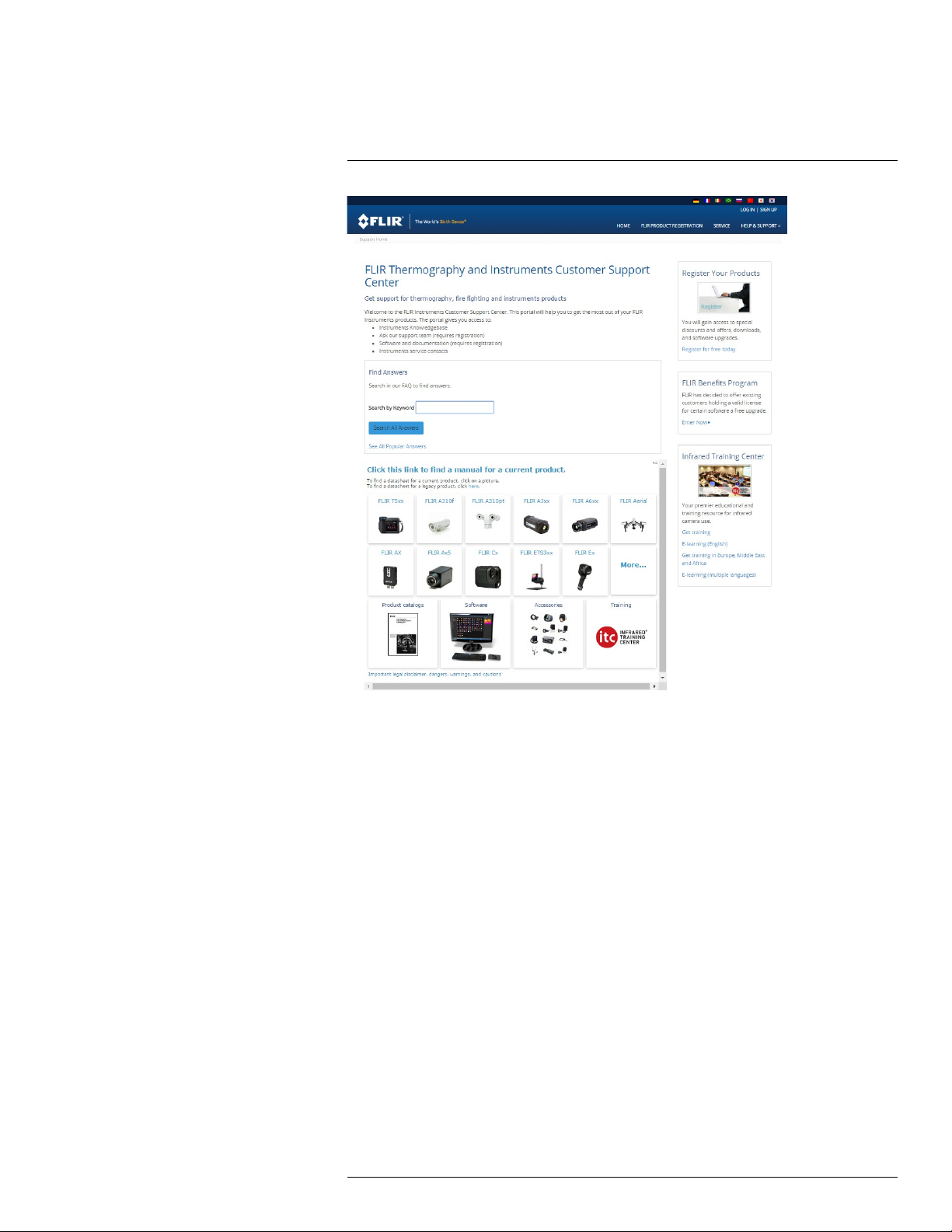
4.1 General
For customer help, visit:
http://support.flir.com
4.2 Submitting a question
To submit a question to the customer help team, you must be a registered user. It only
takes a few minutes to register online. If you only want to search the knowledgebase for
existing questions and answers, you do not need to be a registered user.
When you want to submit a question, make sure that you have the following information to
hand:
• The camera model
• The camera serial number
• The communication protocol, or method, between the camera and your device (for example, SD card reader, HDMI, Ethernet, USB, or FireWire)
• Device type (PC/Mac/iPhone/iPad/Android device, etc.)
• Version of any programs from FLIR Systems
• Full name, publication number, and revision number of the manual
#T559157; r. AH/45951/45951; en-US
12
Page 25

4
Customer help
4.3 Downloads
On the customer help site you can also download the following, when applicable for the
product:
• Firmware updates for your infrared camera.
• Program updates for your PC/Mac software.
• Freeware and evaluation versions of PC/Mac software.
• User documentation for current, obsolete, and historical products.
• Mechanical drawings (in *.dxf and *.pdf format).
• Cad data models (in *.stp format).
• Application stories.
• Technical datasheets.
• Product catalogs.
#T559157; r. AH/45951/45951; en-US
13
Page 26

5
Important note about training and applications
5.1 General
Infrared inspection of gas leaks, furnaces, and high-temperature applications—including
infrared image and other data acquisition, analysis, diagnosis, prognosis, and reporting—
is a highly advanced skill. It requires professional knowledge of thermography and its applications, and is, in some countries, subject to certification and legislation.
Consequently, we strongly recommend that you seek the necessary training before carrying out inspections. Please visit the following site for more information:
http://www.infraredtraining.com
#T559157; r. AH/45951/45951; en-US
14
Page 27

6
List of accessories and services
Product name Part number
Battery charger, incl. power supply with multi plugs T197692
Calibration including General maintenance GF3xx
series
Cigarette lighter adapter kit, 12 VDC, 1.2 m/3.9 ft. T198509
FLIR IR Camera Player DSW-10000
FLIR Reporter Professional (license only) T198586
FLIR ResearchIR 3 (license only) T198578
FLIR ResearchIR 3 Max (license only) T198574
FLIR ResearchIR Max + HSDR 4 T198697
FLIR ResearchIR Max 4 T198696
FLIR ResearchIR Standard 4
FLIR Tools T198584
FLIR Tools Mobile (Android Application) APP-10002
FLIR Tools Mobile (iPad/iPhone Application) APP-10003
FLIR Tools+ (license only) T198583
FLIR VideoReport T198585
Furnace IR lens extender, 14.5° with case for
GF309
Furnace IR lens extender, 24° with case for GF309 T198360
Hard transport case for FLIR GF3xx-Series T197555
HDMI to DVI cable 1.5 m T910816ACC
HDMI to HDMI cable 1.5 m
Heat Shield for FLIR GF309
IR lens, 14.5° with case for GF300, GF309, GF320 T197385
IR lens, 14.5° with case for GF304, GF306 T197384
IR lens, 14.5° with case for GF335, GF346 T198298
IR lens, 24° with case for GF300, GF309, GF320 T197387
IR lens, 24° with case for GF304, GF306 T197386
IR lens, 24° with case for GF335, GF346 T198267
IR lens, 6° with case for GF300, GF309, GF320,
GF346.
ITC Advanced Furnace Application Course - additional student to on site class
ITC Advanced Furnace Application Course - attendance, 1 pers. (3 days)
ITC Advanced Furnace Applications Course group up to 10 pers. (3 days)
ITC Advanced Furnace Applications Course group up to 6 persons (3 days)
ITC Advanced Gas Detection Course - additional
student to on site class, 1 pers.
ITC Advanced Gas Detection Course - attendance,
1 pers.
T199834
T198731
T198361
T910815ACC
T197482
T197388
ITC-ADV-3055
ITC-ADV-3051
ITC-ADV-3059
ITC-ADV-3056
ITC-ADV-3035
ITC-ADV-3031
#T559157; r. AH/45951/45951; en-US
15
Page 28

6
List of accessories and services
Product name Part number
ITC Advanced Gas Detection Course - group of up
to 6 pers. (3 days)
ITC Advanced Gas Detection Course – group of 10
pers.
ITC Advanced training - group of max. 6 pers, additional day 4 for on-site training
ITC conference fee ITC-CON-1001
ITC Customized workshop - per person (per day) ITC-EXP-1041
ITC In-house training - additional attendance 1
pers. (per day)
ITC In-house training - group up to 10 pers. (per
day)
ITC Infrared application and system consultancy
(per day)
ITC Software course - attendance 1 pers. (per day) ITC-SOW-0001
ITC Software course - group up to 10 pers. (per
day)
ITC Training 1 day - attendance 1 pers. ITC-EXP-1001
ITC Training 1 day - group up to 10 pers. ITC-EXP-1009
ITC Training 2 days - attendance 1 pers. ITC-EXP-2001
ITC Training 2 days - group up to 10 pers. ITC-EXP-2009
ITC Training 3 days - attendance 1 pers. ITC-EXP-3001
ITC Training 3 days - group up to 10 pers. ITC-EXP-3009
ITC travel time for instructor ITC-TFT-0100
Li-Ion Battery pack 7.4V 33Wh T198511
Memory card SDHC 4 GB T911230ACC
One year extended warranty for GF3xx series T199825
Power supply, incl. multi plugs T910814
ThermoVision™ LabVIEW® Digital Toolkit Ver. 3.3 T198566
ThermoVision™ System Developers Kit Ver. 2.6
Travel and lodging expenses instructor (Center
and South Africa)
Travel and lodging expenses instructor (Europe,
Balcans, Turkey, Cyprus)
Travel and lodging expenses instructor (other) ITC-TOL-1005
Travel and lodging expenses instructor (Russia/
GUS, Middle East, North Africa)
Travel and lodging expenses instructor (various) ITC-TOL-1004
USB cable Std A <-> Mini-B
Wi-Fi USB micro adapter T951387
ITC-ADV-3036
ITC-ADV-3039
ITC-ADV-4006
ITC-EXP-1021
ITC-EXP-1029
ITC-EXP-1050
ITC-SOW-0009
T198567
ITC-TOL-1003
ITC-TOL-1001
ITC-TOL-1002
1910423
Note FLIR Systems reserves the right to discontinue models, parts or accessories, and
other items, or to change specifications at any time without prior notice.
#T559157; r. AH/45951/45951; en-US
16
Page 29

7
Introduction
7.1 FLIR GF300
7.1.1 Optical gas imaging of methane and other volatile organic compounds
(VOCs)
The FLIR GF300 is an IR camera for optical gas imaging (OGI) that visualizes and pinpoints leaks of VOCs, without the need to shut down the operation. The portable camera
also greatly improves operator safety, by detecting emissions at a safe distance, and helps
to protect the environment by tracing leaks of environmentally harmful gases.
The FLIR GF300 is used in industrial settings such as oil refineries, natural gas processing
plants, offshore platforms, chemical/petrochemical industries, and biogas and power generation plants.
7.1.2 Benefits
• Improved efficiency: The FLIR GF300 reduces revenue loss by pinpointing even small
gas leaks quickly and efficiently, and from a distance. It also reduces the inspection
time by allowing a broad area to be scanned rapidly and without the need to interrupt
the industrial process.
• Increased worker safety: OGI allows gas leaks to be detected in a non-contact mode
and from a safe distance. This reduces the risk of the inspector being exposed to invisible and potentially harmful or explosive chemicals. With a FLIR GF300 gas imaging
camera it is easy to scan areas of interest that are difficult to reach with conventional
methods. The camera is ergonomically designed, with a bright LCD and tiltable viewfinder, which facilitates its use over a full working day.
• Protecting the environment: Several VOCs are dangerous to human health or cause
harm to the environment, and are usually governed by regulations. Even small leaks
can be detected and documented using theFLIR GF300 camera.
7.2 FLIR GF304
7.2.1 Optical gas imaging of refrigerant gases
The FLIR GF304 is an IR camera for optical gas imaging (OGI) that visualizes and pinpoints leaks of refrigerant gases, without the need to shut down the operation. This portable camera also greatly improves operator safety, by detecting gases at a safe distance,
and helps to protect the environment by tracing leaks of environmentally harmful gases.
Refrigerant gases are found in, for example, the food, chemical/petrochemical and automotive industries, as well as in air-conditioning systems.
7.2.2 Benefits
• Improved efficiency: The FLIR GF304 reduces revenue loss by pinpointing even small
gas leaks quickly and efficiently, and from a distance. It also reduces the inspection
time by being able to scan a broad area rapidly without the need to interrupt the industrial process. The wireless connectivity of the camera allows you to connect to smart
phones or tablet PCs for the wireless transfer of images or the remote control of the
camera. The FLIR GF304 can also be used for temperature measurement, which
makes it even more useful for predictive maintenance.
• Increased worker safety: The leak detection of gases can be performed in noncontact
mode, and from a safe distance. This reduces the risk of the inspector being exposed
to invisible and potentially harmful or explosive chemicals. With a FLIR GF304 gasimaging camera it is easy to scan areas of interest that are difficult to reach with
#T559157; r. AH/45951/45951; en-US
17
Page 30

7
Introduction
conventional methods. The camera is ergonomically designed with a bright LCD and a
tiltable viewfinder, which facilitates its use over a full working day.
• Protecting the environment: Several refrigerant gases have a high global warming potential and are usually governed by regulations. Even small leaks can be detected and
documented using the FLIR GF304 camera.
7.3 FLIR GF306
7.3.1 Optical gas imaging especially of SF6 and ammonia
The FLIR GF306 is an IR camera for optical gas imaging (OGI) that visualizes and pinpoints gas leaks of SF6 and ammonia, without the need to de-energize high-voltage
equipment or shut down the operation. The portable camera also greatly improves operator safety, by detecting emissions at a safe distance, and helps to protect the environment
by tracing leaks of environmentally harmful gases.
SF6 is used in the electric power industry as an insulator and quenching medium for gasinsulated substations and circuit breakers. The gas is also used in magnesium production
and semiconductor manufacture. Ammonia is produced in ammonia plants, and is used
mainly for the production of fertilizers.
7.3.2 Benefits
• Improved efficiency: The FLIR GF306 reduces revenue loss by pinpointing even small
gas leaks quickly and efficiently, and from a distance. It also reduces the inspection
time by allowing a broad area to be scanned rapidly and without the need to de-energize components in the high-voltage area. The wireless connectivity of the camera allows you to connect to smart phones or tablet PCs for the wireless transfer of images or
remote control of the camera. The FLIR GF306 can also be used for temperature measurement, which makes it even more useful for predictive maintenance of high-voltage
equipment.
• Increased worker safety: OGI allows gas leaks to be detected in a non-contact mode
and from a safe distance. This prevents electrical exposure to personnel working in a
high-voltage area. With a FLIR GF306 gas imaging camera it is easy to scan areas of
interest that are difficult to reach with conventional methods. The camera is ergonomically designed, with a bright LCD and tiltable viewfinder, which facilitates its use over a
full working day.
• Protecting the environment: SF6 is a well-known greenhouse gas that can cause harm
to the environment, and is usually governed by regulations. SF6 has a global warming
potential 24,000 times higher than CO2. Even small leaks can be detected and documented using the FLIR GF306 camera.
7.4 FLIR GF309
7.4.1 IR camera for furnace and high temperature inspection
The FLIR GF309 is an IR camera for the high-temperature measurement of industrial furnaces, chemical heaters, and coal-fired boilers, without the need to shut down the operation. The portable camera also greatly improves operator safety, by measuring through
flames at a safe distance, for all types of furnaces. A good knowledge of the furnace condition can avert failures and unscheduled shutdowns
Industrial furnaces, heaters, and boilers are found in the chemical, petrochemical, and utility industries.
#T559157; r. AH/45951/45951; en-US
18
Page 31

7
Introduction
7.4.2 Benefits
• Improved efficiency: The FLIR GF309 reduces inspection time by measuring the temperature through flames without the need to interrupt the industrial process or await
scheduled service shutdowns. A furnace camera can help you to determine how to run
a furnace/boiler efficiently to give the best fuel economy and maximize production output and quality. As the FLIR GF309 has a wide temperature range, high-accuracy electrical and mechanical inspections can be performed, which makes the camera even
more useful for predictive maintenance.
• The wireless connectivity of the camera allows you to connect to smart phones or tablet
PCs for the wireless transfer of images or the remote control of the camera—a useful
function if regulations require a second person to accompany the furnace inspector or
thermal images needs to be sent quickly for a second opinion.
• Increased worker safety: High-temperature measurement can be performed through
flames in a non-contact mode, and from a safe distance. Custom-built, the FLIR GF309
also features a detachable heat-shield designed to reflect heat away from the camera
and the camera operator, providing increased protection. The camera is ergonomically
designed with a bright LCD and tiltable viewfinder, which facilitates its use over a full
working day.
• Increased furnace safety: Good knowledge of furnace/boiler condition and operating
parameters can provide the information needed to avert catastrophic failures and prevent unscheduled shutdowns.
7.5 FLIR GF320
7.5.1 Optical gas imaging of methane and other volatile organic compounds
(VOCs)
The FLIR GF320 is an IR camera for optical gas imaging (OGI) that visualizes and pinpoints leaks of VOCs, without the need to shut down the operation. The portable camera
also greatly improves operator safety, by detecting emissions at a safe distance, and helps
to protect the environment by tracing leaks of environmentally harmful gases.
The FLIR GF320 is used in industrial settings such as oil refineries, natural gas processing
plants, offshore platforms, chemical/petrochemical industries, and biogas and power generation plants.
7.5.2 Benefits
• Improved efficiency: The FLIR GF320 reduces revenue loss by pinpointing even small
gas leaks quickly and efficiently, and from a distance. It also reduces the inspection
time by allowing a broad area to be scanned rapidly and without the need to interrupt
the industrial process. The wireless connectivity of the camera allows you to connect to
smart phones or tablet PCs for the wireless transfer of images or remote control of the
camera. The FLIR GF320 is also used for temperature measurement, which makes it
even more useful for predictive maintenance.
• Increased worker safety: OGI allows gas leaks to be detected in a non-contact mode
and from a safe distance. This reduces the risk of the inspector being exposed to invisible and potentially harmful or explosive chemicals. With a FLIR GF320 gas imaging
camera it is easy to scan areas of interest that are difficult to reach with conventional
methods. The camera is ergonomically designed, with a bright LCD and tiltable viewfinder, which facilitates its use over a full working day.
• Protecting the environment: Several VOCs are dangerous to human health or cause
harm to the environment, and are usually governed by regulations. Even small leaks
can be detected and documented using the FLIR GF320 camera.
#T559157; r. AH/45951/45951; en-US
19
Page 32

7
Introduction
7.6 FLIR GF335
The FLIR GF335 is a high-sensitivity, low-noise, cooled infrared camera for applications
requiring a portable camera able to detect very subtle temperature differences. The high
performance of the camera makes it perfect for the detection of faint heat signatures as
well as for non-destructive testing and quality control applications.
7.6.1 Benefits
• High performance: The FLIR GF335 features a cooled 3–5 µm InSb detector that produces razor-sharp thermal images. Its high sensitivity of <15 mK and high accuracy of
±1°C (±1.8°F) or 1% allow the user to detect very subtle temperature differences with
astounding clarity.
• Improved efficiency: The wireless connectivity of the FLIR GF335 allows connection to
smart phones and tablets for the wireless transfer of images or the remote control of
the camera—a useful function if a second person is required to accompany the inspector . The camera also features built-in radiometric video recording, and can store
MPEG-4 thermal and/or standard video on an SD card. The camera has an integrated
GPS and a digital camera, and is compatible with Flir Tools, Flir Reporter, and Flir Researcher software.
• Thought-through ergonomics for everyday use:The FLIR GF335 is ergonomically designed, with a bright LCD and tiltable viewfinder, which facilitates its use over a full
working day. A multi-angle handle with integrated direct access buttons also improves
the ergonomics.
7.7 FLIR GF343
7.7.1 The new FLIR GF343 is an optical gas camera for visualizing carbon dioxide
(CO
2
With this camera you can quickly and easly find gas leaks where CO2is the main
component.
Key features:
• Visualizes gas leaks in real time.
• Inspects without interruption of process.
• Traces leaks to its source.
7.7.2 Main applications
Carbon capture and storage—stop the escalation of global warming:
• A global transition to sustainable low-carbon economy.
• A global energy demand still dominated by fossil fuels being combusted in quantities incompatible with levels required to stabilize greenhouse gases concentrations at safe
levels in the atmosphere.
CO
(R744)—the new environmental friendly refrigerant:
2
• Air-conditioning for cars—replaces R134a.
• CO
• Electrical power—replaces SF
CO
• H
• Use CO
based heat pumps.
2
.
6
—a harmless tracer gas:
2
S applications often use a large amount of CO2.
2
to trace leaks.
2
#T559157; r. AH/45951/45951; en-US
20
Page 33

7
Introduction
7.8 FLIR GF346
7.8.1 Optical gas imaging especially of carbon monoxide (CO) and other harmful
gases
The FLIR GF346 is an IR camera for optical gas imaging (OGI) that visualizes and pinpoints gas leaks of CO, without the need to shut down the operation. The portable camera
also greatly improves operator safety, by detecting emissions at a safe distance, and helps
to protect the environment by tracing leaks of environmentally harmful gases.
CO is an industrial gas with applications in the steel industry and bulk chemicals manufacturing. It is also used for packaging systems for fresh meat and fish.
7.8.2 Benefits
• Improved efficiency: The FLIR GF346 reduces revenue loss by pinpointing even small
gas leaks quickly and efficiently, and from a distance. It also reduces the inspection
time by allowing a broad area to be scanned rapidly and without the need to interrupt
the industrial process. The wireless connectivity of the camera allows you to connect to
smart phones or tablet PCs for the wireless transfer of images or remote control of the
camera. The FLIR GF346 can also be used for temperature measurement, which
makes it even more useful for predictive maintenance.
• Increased worker safety: CO can be toxic to humans when encountered in higher concentrations. OGI allows gas leaks to be detected in a non-contact mode and from a
safe distance. This reduces the risk of the inspector being exposed to invisible and
highly toxic gases or explosive chemicals. With a FLIR GF346 gas imaging camera it is
easy to scan areas of interest that are difficult to reach with conventional methods. The
camera is ergonomically designed, with a bright LCD and tiltable viewfinder, which facilitates its use over a full working day.
• Protecting the environment: Several gases, like CO, have a high global warming potential, and are usually governed by regulations. Even small leaks can be detected and
documented using the FLIR GF346 camera.
#T559157; r. AH/45951/45951; en-US
21
Page 34

8
Example images
8.1 General
This section contains example images from various applications.
Note Gas leaks are easier to see in live image mode, which is the reason the leaks are
indicated with a red dot in the images below.
8.2 Images
#T559157; r. AH/45951/45951; en-US
22
Page 35

9
Quick Start Guide
9.1 Detecting a temperature
CAUTION
In furnace and other high-temperature applications, you must mount the heatshield on the camera. Using
the camera in furnace and other high-temperature applications without the heatshield can cause damage
to the camera.
For instructions on how to mount the heatshield, see 16.12 Mounting the heatshield, page 54.
9.1.1 Procedure
Follow this procedure to get started right away:
1. Charge the battery for four hours, or until the green battery condition LED glows contin-
uously, before starting the camera for the first time.
Note Do this at room temperature, with the camera turned off.
2. Insert an SD Memory Card into a card slot
3. To turn on the camera, push the
Note When you turn on the camera, a mechanical cooler will begin cooling down the
infrared detector. The cooler has a sound that resembles a subdued motor. This sound
is normal. The cooling procedure will typically take 7 minutes for FLIR GF300, FLIR
GF309, FLIR GF320, and 10 minutes for FLIR GF306. In high ambient temperatures
the cooling times may increase 30% or more.
4. Turn the mode wheel to
5. For furnace and other high-temperature applications, mount the heatshield on the
camera. You must also enter the correct external optics transmission value of the heatshield into the camera. The external optics transmission value is printed on a label on
the inside of the heatshield. You enter the external optics transmission value in the object parameters dialog on the Edit tab.
When you remove the heatshield you must reset the external optics transmission to
1.0.
6. Push the temperature range button, then do the following:
6.1. Move the joystick up/down to choose a suitable temperature range for your
object.
6.2. Push the temperature range button to confirm and leave the setup mode.
7. Aim the camera towards the object of interest.
8. Autofocus the camera by pushing the center of the
9. Push the
10. Move the joystick left/right to the Edit tab.
11. Move the joystick up/down to Add spot.
12. Push the joystick. A spotmeter is now displayed in the middle of the screen. The temperature is displayed in the result table in the top left corner of the screen.
button.
.
button.
button.
13. To save an image directly, push and hold the
#T559157; r. AH/45951/45951; en-US
button for more than one second.
23
Page 36

9
Quick Start Guide
14. To move the image to a computer, do one of the following:
• Remove the SD Memory Card and insert it in a card reader connected to a
computer.
• Connect a computer to the camera using a USB mini-B cable.
15. Move the image from the card or camera, respectively, using a drag-and-drop
operation.
9.1.2 Related topics
• 16.1.1 Charging the battery using the power supply cable, page 46
• 16.1.2 Charging the battery using the stand-alone battery charger, page 46
• 16.2.1 Installing the battery, page 47
• 15.4 Inserting SD Memory Cards, page 44
• 16.3 Turning on the camera, page 49
• 18.1 Laying out a measurement tool, page 64
• 17.1 Saving infrared images, page 60
9.2 Detecting a gas leak
9.2.1 Procedure
Follow this procedure to get started right away:
1. Charge the battery for four hours, or until the green battery condition LED glows continuously, before starting the camera for the first time.
Note Do this at room temperature, with the camera turned off.
2. Insert an SD Memory Card into a card slot.
3. To turn on the camera, push the
Note When you turn on the camera, a mechanical cooler will begin cooling down the
infrared detector. The cooler has a sound that resembles a subdued motor. This sound
is normal. The cooling procedure will typically take 7 minutes for FLIR GF300, FLIR
GF309, FLIR GF320, and 10 minutes for FLIR GF306. In high ambient temperatures
the cooling times may increase 30% or more.
4. Turn the mode wheel to
5. Push the temperature range button, then do the following:
5.1. Move the joystick up/down to choose a suitable temperature range for your
object.
5.2. Push the temperature range button to confirm and leave the setup mode.
.
button.
6. Aim the camera towards the target of interest.
7. Autofocus the camera by pushing the center of the
8. If there is a gas leak, and the gas is one of the gases that the camera can detect, you
will now see the leak on the screen. The leak will resemble smoke plume emanating
from the point of the leak.
9. To start recording a video clip, push the
#T559157; r. AH/45951/45951; en-US
button.
button.
24
Page 37

9
Quick Start Guide
10. To stop recording a video clip, push the
button again.
11. To move the video clip to a computer, do one of the following:
• Remove the SD Memory Card and insert it in a card reader connected to a
computer.
• Connect a computer to the camera using a USB mini-B cable.
12. Move the video clip from the card or camera, respectively, using a drag-and-drop
operation.
9.2.2 Related topics
• 16.1.1 Charging the battery using the power supply cable, page 46
• 16.1.2 Charging the battery using the stand-alone battery charger, page 46
• 16.2.1 Installing the battery, page 47
• 15.4 Inserting SD Memory Cards, page 44
• 16.3 Turning on the camera, page 49
• 18.1 Laying out a measurement tool, page 64
• 17.1 Saving infrared images, page 60
• 20 Recording video clips, page 69
#T559157; r. AH/45951/45951; en-US
25
Page 38

10
FLIR GF3xx series series general instrument check
The following general instrument check process ensures that the camera can detect the
intended gas compounds with the same sensitivity as when originally manufactured.
1. Make sure that the camera powers on.
2. Make sure that the camera completes the cool-down process and produces a live infrared image.
3. Make sure that the camera does not report any error messages on startup.
4. Make sure that the camera focuses properly.
5. Make sure that the camera is able to engage HSM mode.
#T559157; r. AH/45951/45951; en-US
26
Page 39

11
A note about ergonomics
11.1 General
To prevent overstrain injuries, it is important that you hold the camera ergonomically correct. This section gives advice and examples on how to hold the camera.
Note Please note the following:
• Always tilt the viewfinder to fit your work position.
• Always adjust the viewing angle of the display to fit your work position.
• Always adjust the camera grip to fit your work position.
• When you hold the camera, make sure that you support the camera housing with your
left hand too. This decreases the strain on your right hand.
11.2 Figure
#T559157; r. AH/45951/45951; en-US
27
Page 40

A note about ergonomics11
11.3 Related topics
• 16.5 Adjusting the viewing angle of the viewfinder, page 49
• 16.7 Adjusting the camera grip, page 50
• 16.9 Adjusting the viewing angle of the display, page 52
#T559157; r. AH/45951/45951; en-US
28
Page 41

12
Camera parts
12.1 View from the left
12.1.1 Figure
12.1.2 Explanation
1. Programmable button for one of the following functions:
• Change the zoom factor.
• Hide/show graphics.
• Change the polarity.
• Change the palette.
You program the button in setup mode
2. Temperature range button.
3. Mode wheel
• Camera mode: Save images.
• Video mode: Record video clips and video sequences.
• Archive mode: View saved images, video clips, and video sequences.
• Program mode: Set up periodical saving of images.
• Setup mode: Change the general settings.
4. Laser button.
5. Button to go between infrared mode and digital camera mode.
with the following modes:
in the Preferences tab.
#T559157; r. AH/45951/45951; en-US
29
Page 42

12
Camera parts
12.2 View from the right
12.2.1 Figure
12.2.2 Explanation
1. Camera handle.
2. Laser pointer.
3. Digital video camera.
4. Digital camera lamps. When you are in digital camera mode, you turn on the lamps by
pushing the joystick.
5.
6. A/M button (Auto/Manual).
button (Preview/Save).
The
sequences):
• To preview an image before saving it, push and release the button.
• To save an image directly, push and hold the button for more than 1 second.
The A/M button has the following functions:
• Push and release the button to change the image adjustment method between Auto,
• Push and hold down the button for more than 1 second to calibrate the camera.
Note This is typically not needed during normal operating procedures.
button has the following functions (not applicable to video clips and video
Manual, and HSM.
Note HSM mode does not apply to the FLIR GF309.
#T559157; r. AH/45951/45951; en-US
30
Page 43

12
Camera parts
7.
The
When an image is in live mode:
• To adjust the focus, push the button left/right.
• To autofocus, push the center of the
When an image is in preview or saved mode:
• To adjust the zoom, push the
8. Hand strap.
9. Focus ring on the infrared lens.
10. Infrared lens.
button.
button has the following functions:
12.3 View from the rear
12.3.1 Figure
button.
button left/right.
12.3.2 Explanation
1. Viewfinder.
2. Adjustment knob for the viewfinder’s diopter correction.
3. Cover for the connector compartment.
4. Cover for the battery compartment.
5. Release button for the battery compartment cover.
6. USB-A connector for external USB devices.
7. Power LED indicator.
8.
#T559157; r. AH/45951/45951; en-US
button (On/off).
The
• When the camera is off, push and release to turn on the camera.
• When the camera is on, push and hold for more than 0.2 second to turn off the
button has the following functions:
camera.
31
Page 44
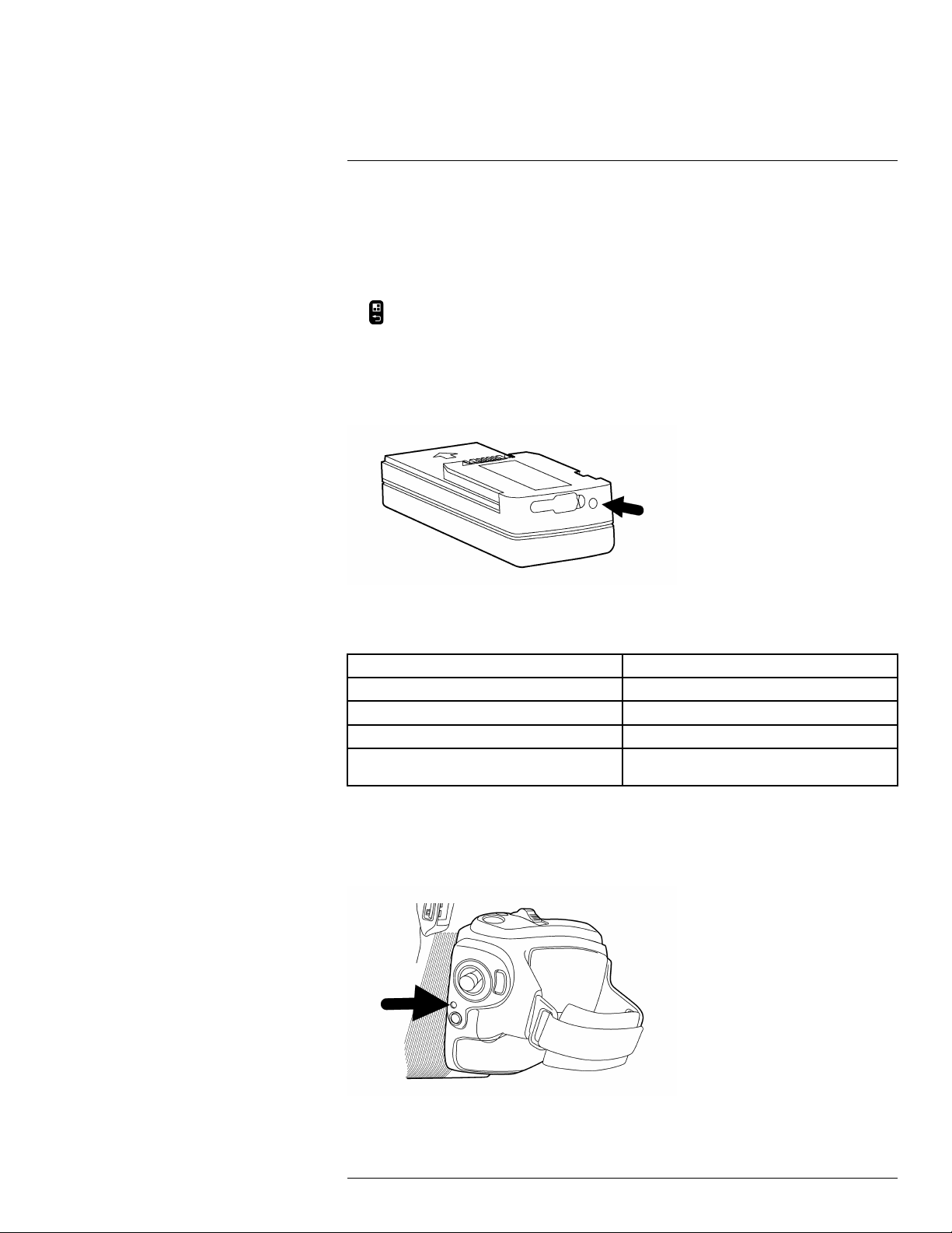
12
Camera parts
9. Joystick.
The joystick has the following functions:
• To navigate in menus and dialog boxes, move the joystick up/down/left/right.
• To change values, move the joystick up/down/left/right.
• To select or confirm choices, push the joystick.
10.
button (Menu/Back).
12.4 Battery condition LED indicator
12.4.1 Figure
12.4.2 Explanation
This table gives an explanation of the battery condition LED indicator:
Type of signal Explanation
The LED is red and glows continuously. The battery needs to be charged..
The LED is green and flashes. The battery is being charged.
The LED is green and glows continuously. The battery is fully charged.
The LED is off. The power supply or the stand-alone battery
charger is disconnected from the battery.
12.5 Power LED indicator
12.5.1 Figure
#T559157; r. AH/45951/45951; en-US
32
Page 45
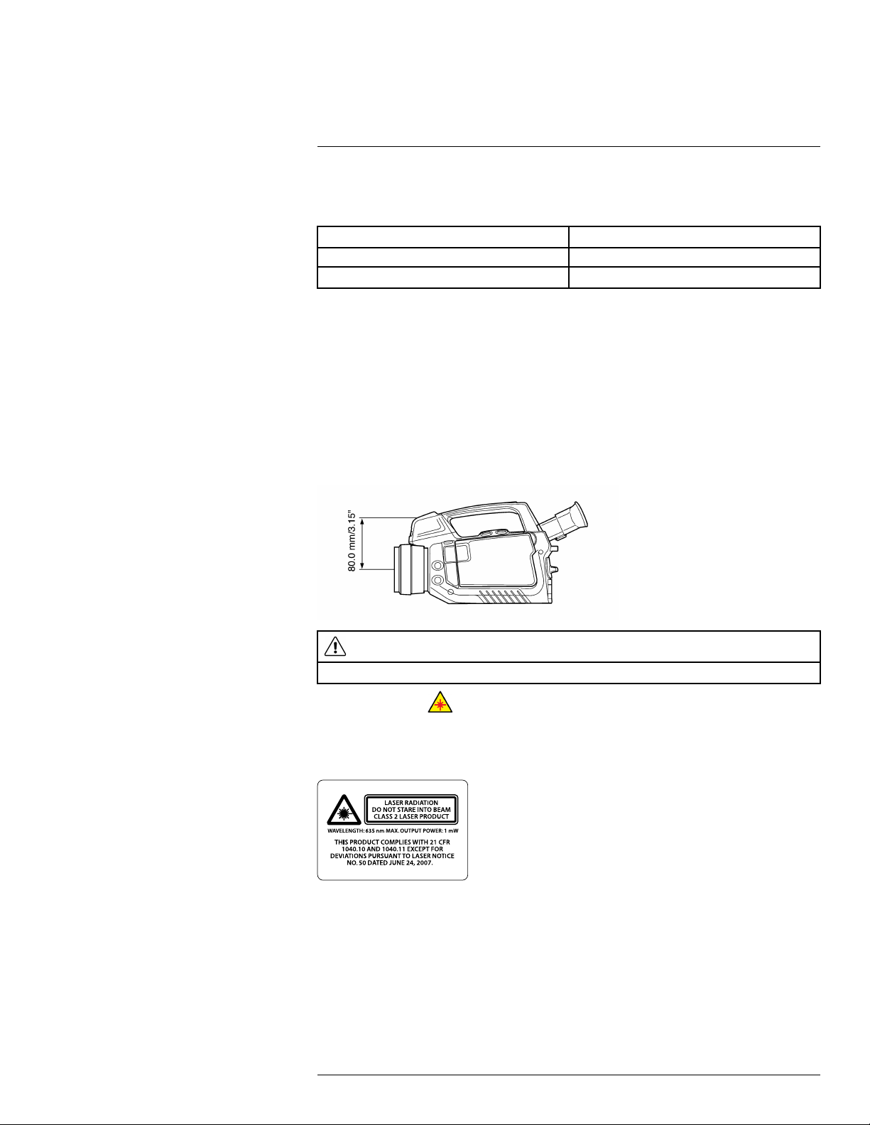
12
Camera parts
12.5.2 Explanation
This table gives an explanation of the power LED indicator:
Type of signal Explanation
The LED is off. The camera is off.
The LED is green. The camera is on.
12.6 Laser pointer
12.6.1 General
The camera has a laser pointer. When the laser pointer is on, you will see a laser dot approximately 80 mm (3.15″) above the target.
12.6.2 Figure
This figure shows the difference in position between the laser pointer and the optical center of the infrared lens:
WARNING
Do not look directly into the laser beam. The laser beam can cause eye irritation.
Note The symbol is displayed on the screen when the laser pointer is on.
12.6.3 Laser warning label
A laser warning label with the following information is attached to the camera:
12.6.4 Laser rules and regulations
Wavelength: 635 nm. Maximum output power: 1 mW.
This product complies with 21 CFR 1040.10 and 1040.11 except for deviations pursuant
to Laser Notice No. 50, dated June 24, 2007.
#T559157; r. AH/45951/45951; en-US
33
Page 46

13
Screen elements
13.1 Mode selector
Note To select the mode, turn the mode wheel on the left side of the camera.
13.1.1 Figure
13.1.2 Explanation
1. Camera mode.
2. Video mode: Record video clips (*.mp4) and video sequences (*.seq).
3. Archive mode: View saved images and video sequences.
4. Program mode: Set up periodical saving of images.
5. Setup mode: Change the general settings.
13.2 Result table and measurement tools
Note To access the measurement tools, push the button.
13.2.1 Figure
13.2.2 Explanation
1. Status bar.
2. Result table.
3. Area (measurement tool).
4. Spotmeter (measurement tool).
5. Line (measurement tool).
6. Adjustment method indicator.
#T559157; r. AH/45951/45951; en-US
34
Page 47

13
Screen elements
7. Temperature scale.
13.3 Toolbox, indicators, and other objects
13.3.1 Figure
13.3.2 Explanation
1. Menu tab.
2. Mode indicator.
3. Menu tab name.
4. Menu item.
5. Status indicators:
• Time.
• Date.
• GPS indicator.
• USB indicator.
• Power indicator (battery or mains supply).
• SD memory card indicator (“I” or “II”). The indicator also shows the amount of free
space on the SD memory card. As a warning, the indicator will turn yellow and then
red as the amount of free space decreases.
#T559157; r. AH/45951/45951; en-US
35
Page 48

14
Achieving a good image
14.1 General
A good image depends on several different settings, although some settings affect the image more than other.
These are the settings you need to experiment with:
• Adjusting the infrared camera focus.
• Adjusting the image, using Auto, Manual, or HSM (= High Sensitivity Mode).
• Selecting a suitable temperature range.
• Selecting a suitable color palette.
• Enabling or disabling histogram mode.
• Enabling or disabling inverted color palette.
• Changing object parameters.
This section explains how to change these settings.
14.2 Adjusting the infrared camera focus
manually
Note Do not touch the lens surface when you adjust the infrared camera focus manually.
If this happens, clean the lens according to the instructions in 25.2 Infrared lens, page 229.
14.2.1 Figure
14.2.2 Procedure
Do one of the following:
• For far focus, rotate the focus ring counter-clockwise (looking at the front of the lens)
• For near focus, rotate the focus ring clock-wise (looking at the front of the lens)
#T559157; r. AH/45951/45951; en-US
36
Page 49

Achieving a good image14
14.3 Adjusting the infrared camera focus
14.3.1 Figure
14.3.2 Procedure
Follow this procedure to adjust the infrared camera focus:
1. Make sure that the image is in live mode.
2. To adjust the camera focus, push the
button left/right.
14.4 Adjusting an image
14.4.1 General
Depending on camera model, an image can be adjusted in several different ways.
14.4.2 Explanation of the adjustment methods
Auto An adjustment method that will automatically adjust the image for best brightness
HSM HSM = High Sensitivity Mode.
Manual An adjustment method where you manually set the suitable temperature level and
14.4.3 Procedure (Auto)
Follow this procedure to adjust an image using the Auto method:
and contrast.
An adjustment method that is specifically designed for gas detection applications.
Working in this mode, you can change the sensitivity to optimize the image quality.
temperature span according to the temperature of the objects in the scene.
For gas detection applications, this mode lets you center on the temperatures
around the background of the gas, so as to make the gas appear more clearly.
1. Turn the mode wheel to
#T559157; r. AH/45951/45951; en-US
or .
37
Page 50

Achieving a good image14
2. Push the A/M button to select Auto. The image will now be continuously adjusted for
best image brightness and contrast.
14.4.4 Figure
This figure shows the HSM slider:
14.4.5 Procedure (HSM)
Follow this procedure to adjust an image using the HSM method:
1. Turn the mode wheel to
2. Push the A/M button to select HSM. To change the sensitivity, move the joystick left/
right.
You will need to experiment with this setting until you get a clear image of a verified gas
leak.
14.4.6 Procedure (Manual)
Follow this procedure to adjust an image using the Manual method:
1. Turn the mode wheel to
2. Push the A/M button to select Manual, then do one of the following:
• To change the temperature level, move the joystick up/down.
• To change the temperature span, move the joystick left/right.
or .
or .
14.5 Selecting a suitable temperature range
14.5.1 About temperature ranges
14.5.1.1 General
The camera has three different types of ranges. Within each type of range, there are several subranges. You must choose a suitable range for your object.
#T559157; r. AH/45951/45951; en-US
38
Page 51

Achieving a good image14
14.5.1.2 Types of temperature ranges
Type
1
2 Temperature range +10°C to +50°C (+50°F
3 Temperature span
Name
Characteristic temperature range
Example Explanation
–40°C to +350°C (–40°
F to +662°F)
to +122°F)
+23.8°C to +25.9°C
(+74.8°F to +78.6°F)
All temperatures the
camera can register.
This range is the total
sum of the temperature
ranges (type no. 2
below).
The span of temperatures that the camera
can register with the
current settings.
This type of range is a
subrange to type no. 1
above.
The range of temperatures that the camera
registers when aimed at
a particular scene with
a particular temperature
range set.
14.5.2 Understanding the temperature scale
14.5.2.1 Figure
14.5.2.2 Explanation
1. Currently set minimum temperature in the temperature span (= range of type 3 in the
table 14.5.1.2 Types of temperature ranges, page 39).
2. Currently set maximum temperature in the temperature span (= range of type 3 in the
table 14.5.1.2 Types of temperature ranges, page 39).
3. Currently set maximum temperature in the range that the camera can register with the
current settings (= range of type 2 in the table 14.5.1.2 Types of temperature ranges,
page 39).
4. Indicator that represents the temperature range (= range of type 2 in the table 14.5.1.2
Types of temperature ranges, page 39).
5. Indicator that represents the temperature span (= range of type 3 in the table 14.5.1.2
Types of temperature ranges, page 39).
#T559157; r. AH/45951/45951; en-US
39
Page 52

Achieving a good image14
6. Currently set minimum temperature in the range that the camera can register with the
current settings (= range of type 2 in the table 14.5.1.2 Types of temperature ranges,
page 39).
14.5.3 Changing the temperature range
14.5.3.1 Procedure
Follow this procedure to change the temperature range:
1. Do one of the following:
• Push the temperature range button on the left side of the camera.
• Push the
2. Move the joystick up/down to choose a suitable temperature range for your object.
3. Push the temperature range button to confirm and leave the setup mode.
button, then select Adjust temp. range.
14.6 Selecting a suitable color palette
14.6.1 Procedure
1. Turn the mode wheel to
2. Push the
3. Move the joystick left/right to go to the Image tab.
4. Move the joystick up/down to go to select Color palette.
5. Push the joystick to enable the list of palettes.
6. Move the joystick up/down to select a new palette.
7. Push the joystick.
8. Push the
button to display a menu.
button to leave the setup mode.
or .
14.7 Enabling or disabling histogram mode
14.7.1 General
Histogram mode is an image-displaying method that evenly distributes the color information over the existing temperatures of the image.
14.7.2 Procedure
1. Turn the mode wheel to
2. Push the
3. Move the joystick left/right to go to the Image tab.
4. Move the joystick up/down to go to select Histogram.
5. Push the joystick to enable/disable the setting.
6. Push the
#T559157; r. AH/45951/45951; en-US
button to display a menu.
button to leave the setup mode.
or .
40
Page 53

Achieving a good image14
14.8 Enabling or disabling inverted color palette
14.8.1 Procedure
1. Turn the mode wheel to
2. Push the
3. Move the joystick left/right to go to the Image tab.
4. Move the joystick up/down to go to select Invert palette.
5. Push the joystick to enable/disable the setting.
6. Push the
button to display a menu.
button to leave the setup mode.
or .
14.9 Changing object parameters
14.9.1 General
For accurate measurements, you must set the object parameters. You can do this locally
or globally. This procedure describes how to change the object parameters globally.
14.9.2 Types of parameters
The camera can use these object parameters:
• Emissivity, i.e., how much radiation an object emits, compared to the radiation of a the-
oretical reference object of the same temperature (called a “blackbody”). The opposite
of emissivity is reflectivity. The emissivity determines how much of the radiation originates from the object as opposed to being reflected by it.
• Reflected apparent temperature, which is used when compensating for the radiation
from the surroundings reflected by the object into the camera. This property of the object is called reflectivity.
• Object distance, i.e., the distance between the camera and the object of interest.
• Atmospheric temperature, i.e., the temperature of the air between the camera and the
object of interest.
• Relative humidity, i.e., the relative humidity of the air between the camera and the ob-
ject of interest.
• External optics temperature, i.e., the temperature of any protective windows etc. that
are set up between the camera and the object of interest. If no protective window or
protective shield is used, this value is irrelevant.
• External optics transmission, i.e., the optical transmission of any protective windows,
etc. that are set up between the camera and the object of interest.
Note For furnace and other high-temperature applications, mount the heatshield on
the camera. You must also enter the correct external optics transmission value of the
heatshield into the camera. The external optics transmission value is printed on a label
on the inside of the heatshield. You enter the external optics transmission value in the
object parameters dialog on the Edit tab.
When you remove the heatshield you must reset the external optics transmission to 1.0.
14.9.3 Recommended values
If you are unsure about the values, the following values are recommended:
Emissivity 0.95
Distance 1.0 m (3.3 ft.)
#T559157; r. AH/45951/45951; en-US
41
Page 54

Achieving a good image14
Reflected apparent temperature
Relative humidity 50%
Atmospheric
temperature
+20°C (+69°F)
+20°C (+69°F)
14.9.4 Procedure
Follow this procedure to change the object parameters globally:
1. Turn the mode wheel to
2. Push the
button to display a menu.
or .
3. Move the joystick left/right to go to the Edit tab.
4. Move the joystick up/down to select Object parameters.
5. Push the joystick to display a dialog box.
6. Move the joystick up/down to select the parameter you want to change, then push the
joystick.
7. Move the joystick up/down to change the value, then push the joystick.
8. Push the
button to confirm and leave the setup mode.
Note
• Of the seven parameters above, emissivity and reflected apparent temperature are the
two most important to set correctly in the camera.
• To change object parameters locally, first select a measurement tool in the toolbox, then
select Use local parameters. Change the local parameters by selecting Edit local pa-
rameters, then edit them in the same way as for global object parameters.
14.9.5 Related topics
• For in-depth information about parameters, and how to correctly set emissivity and re-
flected apparent temperature, see 32 Thermographic measurement techniques.
#T559157; r. AH/45951/45951; en-US
42
Page 55

15
Connecting external devices
15.1 General
You can connect the following external devices to the camera:
• A power supply.
• A video monitor or projector, connected using a HDMI cable.
• A computer to move images and other files to and from the camera.
• An external USB device, such as a USB keyboard, USB memory stick, USB-Bluetooth
micro adapter (to connect to a headset), or a USB-WLAN micro adapter (to connect the
camera to a remote control (P/N T197230)).
• One or two SD Memory Cards.
• One or two SDHC Memory cards.
15.2 Related topics
• 15.3 Connecting devices to the rear connectors, page 43
• 15.4 Inserting SD Memory Cards, page 44
15.3 Connecting devices to the rear connectors
15.3.1 Figure
15.3.2 Explanation
1. To connect an external USB device to the camera, use a USB-A cable and this connector. You can also plug in a USB memory stick in this connector, or a USB-Bluetooth
micro adapter. For WLAN connectivity to a remote control (P/N T197230), use a USBWLAN micro adapter.
2. To connect a computer to the camera to move images and files to and from the camera, use a USB mini-B cable and this connector. This connector is also used when
pairing the camera to the remote control (P/N T197230).
3. To play live video from the camera on an external video monitor using the HDMI protocol (High Definition Multimedia Interface), use a HDMI cable and this connector.
#T559157; r. AH/45951/45951; en-US
43
Page 56

15
Connecting external devices
15.3.3 Figure
15.3.4 Explanation
To connect the power supply to the camera, use the power supply cable and this connector. The power connector is protected by a rubber cover.
15.4 Inserting SD Memory Cards
15.4.1 Figure
15.4.2 Explanation
I. To insert an SD Memory Card (identified with Roman numeral ‘I’ in the camera pro-
gram), use this card slot.
Note The connectors on the card shall face up when inserting the card.
II. To insert an SD Memory Card (identified with Roman numeral ‘II’ in the camera pro-
gram), use this card slot.
Note The connectors on the card shall face down when inserting the card.
#T559157; r. AH/45951/45951; en-US
44
Page 57

15
Connecting external devices
15.4.3 Formatting memory cards
For best performance, memory cards should be formatted to the FAT (FAT16) file system.
Using FAT32-formatted memory cards may result in inferior performance. To format a
memory card to FAT (FAT16), follow this procedure:
1. Insert the memory card into a card reader that is connected to a computer running Microsoft Windows.
2. In Windows Explorer, select My Computer and right-click the memory card.
3. Select Format.
4. Under File system, select FAT.
5. Click Start.
Note
• SDHC memory cards that are 4 GB or larger can only be formatted to the FAT32 file
system.
#T559157; r. AH/45951/45951; en-US
45
Page 58

16
Handling the camera
16.1 Charging the camera battery
16.1.1 Charging the battery using the power supply cable
Note
• You must charge the battery for four hours before starting the camera the first time.
After that, you must charge the battery whenever a warning message for low battery
power is displayed on the screen.
• The battery has a battery condition LED indicator. When the green LED glows continu-
ously, the battery is fully charged.
• Charge the battery at room temperature. If you charge the battery when it is inside the
camera, the camera should be turned off. Charging the battery when it is inside the
camera will not result in a fully charged battery.
16.1.1.1 Procedure
Follow this procedure to charge the battery using the power supply cable:
1. Connect the power supply cable plug to the connector on the battery.
2. Connect the power supply wall plug to a mains supply.
3. When the green LED of the battery condition indicator glows continuously, disconnect
the power supply cable.
16.1.1.2 Related topics
• For information about the battery condition LED indicator, see 12.4 Battery condition
LED indicator, page 32.
• For information on how to install and remove the battery, see 16.2.1 Installing the bat-
tery, page 47 and 16.2.2 Removing the battery, page 48.
16.1.2 Charging the battery using the stand-alone battery charger
Note
• You must charge the battery for 4 hours before starting the camera for the first time.
After that, you must charge the battery whenever a warning message for low battery
power is displayed on the screen.
• The battery has a battery condition LED indicator. When the green LED glows continu-
ously, the battery is fully charged.
• Charge the battery at room temperature.
16.1.2.1 Procedure
Follow this procedure to charge the battery using the stand-alone battery charger:
1. Put the battery in the stand-alone battery charger.
2. Connect the power supply cable plug to the connector on the stand-alone battery
charger.
3. Connect the power supply wall plug to a mains supply.
4. When the green LED of the battery condition indicator glows continuously, disconnect
the power supply cable.
16.1.2.2 Related topics
• For information about the battery condition LED indicator, see 12.4 Battery condition
LED indicator, page 32.
• For information on how to install and remove the battery, see 16.2.1 Installing the bat-
tery, page 47 and 16.2.2 Removing the battery, page 48.
#T559157; r. AH/45951/45951; en-US
46
Page 59

Handling the camera16
16.2 Installing and removing the camera battery
16.2.1 Installing the battery
Note Use a clean, dry cloth to remove any water or moisture on the battery before you
install it.
16.2.1.1 Procedure
Follow this procedure to install the battery:
1. Push the release button for the battery compartment upwards.
2. Open the battery compartment cover.
3. Push the battery into the battery compartment.
4. Close the battery compartment cover.
#T559157; r. AH/45951/45951; en-US
47
Page 60

Handling the camera16
16.2.2 Removing the battery
16.2.2.1 Procedure
Follow this procedure to remove the battery:
1. Push the release button for the battery compartment upwards.
2. Open the battery compartment cover.
3. Push the release lever for the battery downward.
Note In this image, the thumb obscures the actual release lever. The mechanism to
the right of the thumb is the locking mechanism for the battery compartment.
4. Pull out the battery from the battery compartment.
#T559157; r. AH/45951/45951; en-US
48
Page 61

Handling the camera16
16.3 Turning on the camera
16.3.1 Procedure
To turn on the camera, push and release the
Note When you turn on the camera, a mechanical cooler will begin cooling down the in-
frared detector. The cooler has a sound that resembles a subdued motor. This sound is
normal. The cooling procedure will typically take 7 minutes for FLIR GF300, FLIR GF309,
FLIR GF320, and 10 minutes for FLIR GF306. In high ambient temperatures the cooling
times may increase 30% or more.
button.
16.4 Turning off the camera
16.4.1 Procedure
To turn off the camera, push and hold the
button for more than 0.2 seconds.
16.5 Adjusting the viewing angle of the
viewfinder
16.5.1 General
To make your working position as comfortable as possible, you can adjust the viewing angle of the viewfinder.
16.5.2 Figure
16.5.3 Procedure
To adjust the viewfinder, tilt the viewfinder up or down.
#T559157; r. AH/45951/45951; en-US
49
Page 62

Handling the camera16
16.6 Adjusting the viewfinder’s dioptric
correction
16.6.1 General
The viewfinder’s dioptric correction can be adjusted for your eyesight.
16.6.2 Figure
16.6.3 Procedure
To adjust the viewfinder’s dioptric correction, look at the displayed text or graphics on the
screen and rotate the adjustment knob clockwise or counter-clockwise for best sharpness.
Note
• Maximum dioptric correction: +2
• Minimum dioptric correction: –2
16.7 Adjusting the camera grip
16.7.1 General
To make your working position as comfortable as possible, you can adjust the angle of the
camera grip.
#T559157; r. AH/45951/45951; en-US
50
Page 63

Handling the camera16
16.7.2 Figure
16.7.3 Procedure
To adjust the camera grip, rotate the camera grip clockwise or counter-clockwise.
16.8 Opening the display
16.8.1 Figure
#T559157; r. AH/45951/45951; en-US
51
Page 64

Handling the camera16
16.9 Adjusting the viewing angle of the display
16.9.1 General
To make your working position as comfortable as possible, you can adjust the viewing angle of the display.
16.9.2 Figure
16.9.3 Procedure
To adjust the viewing angle of the display, rotate the display clockwise or counterclockwise.
16.10 Installing an infrared lens
Note
• Do not touch the lens surface when you install an infrared lens. If this happens, clean
the lens according to the instructions in 25.2 Infrared lens, page 229.
• Depending on license and export procedures, lenses may be permanently fixed to cam-
eras shipped to customers outside United States. Interchangeable lenses fall under U.
S. Department of State jurisdiction.
16.10.1 Procedure
Follow this procedure to install an infrared lens:
#T559157; r. AH/45951/45951; en-US
52
Page 65

Handling the camera16
1. Align the index mark on the lens with the index mark on the bayonet ring.
2. Carefully push the infrared lens into the bayonet ring.
3. Rotate the infrared lens 30° clockwise (looking at the front of the lens).
16.11 Removing an infrared lens
Note
• Do not touch the lens surface when you remove an infrared lens. If this happens, clean
the lens according to the instructions in 25.2 Infrared lens, page 229.
• When you have removed the lens, put the lens caps on the lens to protect it from dust
and fingerprints.
• Depending on license and export procedures, lenses may be permanently fixed to cam-
eras shipped to customers outside United States. Interchangeable lenses fall under U.
S. Department of State jurisdiction.
16.11.1 Procedure
Follow this procedure to remove an infrared lens:
1. Push the release button for the infrared lens forward.
#T559157; r. AH/45951/45951; en-US
53
Page 66

Handling the camera16
2. Rotate the infrared lens counter-clockwise 30° (looking at the front of the lens).
3. Carefully pull out the infrared lens from the bayonet ring.
16.12 Mounting the heatshield
16.12.1 General
In furnace and other high-temperature applications, you must mount the heatshield on the
camera.
You must also enter the correct external optics transmission value of the heatshield into
the camera. The external optics transmission value is printed on a label on the inside of
the heatshield. You enter the external optics transmission value in the object parameters
dialog on the Edit tab.
CAUTION
Using the camera in furnace and other high-temperature applications without the heatshield can cause
damage to the camera.
16.12.2 Procedure
Follow this procedure to mount a heatshield:
1. Remove the two nuts from the heatshield.
#T559157; r. AH/45951/45951; en-US
54
Page 67

Handling the camera16
2. Push the aluminum frame onto the screws.
3. Mount and tighten the two nuts.
4. Align the aluminum frame to the mounting interface on the bottom side of the camera
body. The aluminum frame has an alignment peg that should fit in a hole on the camera
body.
5. Mount the aluminum frame by tightening the mounting screw.
Note When you remove the heatshield you must reset the external optics transmission
to 1.0.
#T559157; r. AH/45951/45951; en-US
55
Page 68

Handling the camera16
16.13 Adjusting the infrared camera focus
manually
Note Do not touch the lens surface when you adjust the infrared camera focus manually.
If this happens, clean the lens according to the instructions in 25.2 Infrared lens, page 229.
16.13.1 Figure
16.13.2 Procedure
Do one of the following:
• For far focus, rotate the focus ring counter-clockwise (looking at the front of the lens)
• For near focus, rotate the focus ring clock-wise (looking at the front of the lens)
#T559157; r. AH/45951/45951; en-US
56
Page 69

Handling the camera16
16.14 Adjusting the infrared camera focus
16.14.1 Figure
16.14.2 Procedure
Follow this procedure to adjust the infrared camera focus:
1. Make sure that the image is in live mode.
2. To adjust the camera focus, push the
button left/right.
#T559157; r. AH/45951/45951; en-US
57
Page 70

Handling the camera16
16.15 Autofocusing the infrared camera and the
digital camera
16.15.1 Figure
16.15.2 Procedure
Follow this procedure to autofocus the infrared camera and the digital camera:
1. Make sure that the image is in live mode.
2. To autofocus, push the center of the
#T559157; r. AH/45951/45951; en-US
button.
58
Page 71

Handling the camera16
16.16 Operating the laser pointer
16.16.1 Figure
16.16.2 Procedure
Follow this procedure to operate the laser pointer:
1. To turn on the laser pointer, push and hold the laser button.
2. To turn off the laser pointer, release the laser button.
WARNING
Do not look directly into the laser beam. The laser beam can cause eye irritation.
Note The symbol is displayed on the screen when the laser pointer is on.
16.16.3 Laser warning label
A laser warning label with the following information is attached to the camera:
16.17 Using the zoom function
16.17.1 General
You can zoom in on infrared images in preview or recall mode. This enables you to view
details in an image.
16.17.2 Procedure
Do one of the following:
• To zoom into a live image, choose Zoom on the second tab in the menu system, then
use the joystick.
• To zoom into a image in recall mode, push the
#T559157; r. AH/45951/45951; en-US
button left/right.
59
Page 72

17
Working with views and images
17.1 Saving infrared images
17.1.1 General
You can save one or more images to an SD Memory Card.
17.1.2 Image capacity
The approximate number of images that can be saved on an SD Memory Card is 2,000
per GB.
17.1.3 Saving an infrared image directly to an SD Memory Card
17.1.3.1 General
You can save an image directly to an SD Memory Card, without previewing the image first.
17.1.3.2 Procedure
Follow this procedure to save an image directly to an SD Memory Card:
1. Turn the mode wheel to
2. To save an image without previewing, push and hold the
second.
17.1.4 Previewing and saving an infrared image to an SD Memory Card
17.1.4.1 General
You can preview an image before you save it to an SD Memory Card. This lets you do one
or more of the following tasks before you save the image:
• Edit measurements.
• Adjust the image.
• Add a digital photo.
• Delete an image.
17.1.4.2 Procedure
Follow this procedure to preview and save an image to an SD Memory Card:
1. Turn the mode wheel to
2. Push and release the
.
button for more than one
.
button. This will display a preview dialog box.
#T559157; r. AH/45951/45951; en-US
60
Page 73

Working with views and images17
3. You can now do one or more of the following tasks before you save the image. Move
the joystick to go to a task and push the joystick to select the task.
• Select
• Select
• Select
lamps by pushing the joystick. Push the
• Select
• Select
to edit measurement tools.
to adjust the image.
to add a digital photo to the image. You turn on the digital camera
button to take a digital photo.
to delete the image.
to save the image.
17.2 Opening an image
17.2.1 General
When you save an image, you store the image on an SD Memory Card. To display the image again, you can open it from the SD Memory Card.
17.2.2 Procedure
Follow this procedure to open an image:
1. Turn the mode wheel to
or an image at full size.
2. In the archive overview, you can do the following:
• Move the joystick up/down/left/right to select the image you want to view.
• Push the joystick. This displays the selected image at full size.
3. When an image is displayed at full size, you can do the following:
to enter archive mode. This displays the archive overview
• Push the joystick or the
lete the image. This displays a menu.
• Move the joystick left/right to view the previous/next image.
• Move the joystick up to return to the archive overview.
4. To leave the archive mode, turn the mode wheel and select another mode.
button to edit the measurements, adjust the image, or de-
17.3 Changing settings related to image
presentation
17.3.1 General
In live mode, you can enable/disable a variety of settings relating to image presentation.
These settings include:
• Zoom, i.e., zoom into or out of images.
• Hide/show graphics, i.e. hide or show the on-screen graphics.
• Change the color palette, i.e. the colors that are used to display the temperatures in the
infrared image.
#T559157; r. AH/45951/45951; en-US
61
Page 74

Working with views and images17
• Invert polarity, i.e. change the image polarity from white = hot to black = hot.
• Histogram equalization, i.e., an image-displaying method that evenly distributes the col-
or information over the existing temperatures of the image.
Note In preview and archive mode, you can do the following related to image
presentation:
• Push the
• Depending on the function you have assigned to the programmable button, you can
hide/show graphics, change the polarity, or change the palette. For more information,
see section , page .
17.3.2 Procedure
1. Turn the mode wheel to
2. Push the
3. Move the joystick left/right to go to the Image tab.
4. Move the joystick up/down to go to select the setting that you want to change.
5. Push the joystick to enable/disable the setting.
(If you select Zoom you can change the zoom factor by moving the joystick up/down.)
6. Push the
button left/right to zoom into or out of the image.
or .
button to display a menu.
button to leave the setup mode.
17.4 Editing a saved image
17.4.1 General
You can edit a saved image. You can do one or more of the following tasks:
• Edit measurements.
• Adjust the image.
• Delete the image.
17.4.2 Procedure
Follow this procedure:
1. Open the image at full size in the archive. For more information, see section 17.2
Opening an image, page 61.
2. Push the joystick or the
3. You can now do one or more of the following tasks. Move the joystick to go to a task
and push the joystick to select the task.
• Select
• Select
Note You can only adjust an image that has been saved in Auto or Manual mode.
An image saved in HSM mode cannot be adjusted. For more information, see section 14.4 Adjusting an image, page 37.
• Select
• Select
#T559157; r. AH/45951/45951; en-US
to edit measurement tools.
to adjust the image.
to delete the image.
. This displays a menu.
to save any changes and exit edit mode.
62
Page 75

Working with views and images17
17.5 Deleting a file
17.5.1 Procedure
Follow this procedure to delete an image file, a video clip, or a video sequence:
1. Turn the mode wheel to
or an image at full size.
2. If an image is displayed at full size, move the joystick up to go to the archive overview.
3. Move the joystick up/down/left/right to select the image you want to delete.
4. Push the
5. Move the joystick up/down to select one of the following:
• Delete
• Delete all
6. Push the joystick.
7. Confirm the deletion and push the joystick.
button to display a menu.
to enter archive mode. This displays the archive overview
#T559157; r. AH/45951/45951; en-US
63
Page 76

18
Working with measurement tools
18.1 Laying out a measurement tool
18.1.1 General
To measure a temperature, you use one or several measurement tools, such as a spotmeter, a box, etc.
18.1.2 Procedure
Follow this procedure to lay out measurement tool:
1. Turn the mode wheel to
2. Push the
3. Move the joystick left/right to go to the Edit tab.
4. Move the joystick up/down to select the measurement tool you want to lay out.
5. Push the joystick. The measurement tool has now been created on the screen.
button to display a menu.
or .
18.2 Moving or resizing a measurement tool
18.2.1 General
You can move and resize a measurement tool.
18.2.2 Procedure
Note This procedure assumes that you have previously laid out a measurement tool on
the screen.
Follow this procedure to move or resize a measurement tool:
1. Turn the mode wheel to
2. Push the
3. Move the joystick left/right to go to the Edit tab.
4. Move the joystick up/down to select the measurement tool that you want to move or
resize.
5. Push the joystick to display a menu.
6. Move the joystick up/down to select Move or Resize.
7. Move the joystick up/down and left/right to move or resize the measurement tool.
8. Push the joystick to confirm.
button to display a menu.
or .
9. Push the
button to leave the setup mode.
18.3 Creating & setting up a difference
calculation
18.3.1 General
A difference calculation returns the difference between the values of two known measurement results, or between the value of a measurement result and the reference
temperature.
#T559157; r. AH/45951/45951; en-US
64
Page 77

Working with measurement tools18
18.3.2 Procedure
Note This procedure assumes that you have previously laid out at least two measure-
ment tools on the screen.
Follow this procedure to create and set up a difference calculation:
1. Turn the mode wheel to
2. Push the
3. Move the joystick left/right to go to the Edit tab.
4. Move the joystick up/down to select Add difference.
5. Push the joystick to display a dialog box.
6. Do the following and push the joystick to confirm each choice:
6.1. To select the first function in the difference calculation, select Function 1 and
6.2. (Not applicable if there is only one measurement tool.) To select the ID of the
6.3. (Not applicable to spotmeter and reference temperature.) To select the result
7. Do the following and push the joystick to confirm each choice:
7.1. To select the second function in the difference calculation, select Function 2
7.2. (Not applicable if there is only one measurement tool.) To select the ID of the
7.3. (Not applicable to spotmeter.) To select the result type of the measurement tool
button to display a menu.
push the joystick. Move the joystick up/down to select the measurement tool
you want to use for this function.
measurement tool, select Id and push the joystick. Move the joystick up/down
to select the ID.
type of the measurement tool (Min., Max., Avg.), select Type and push the joy-
stick. Move the joystick up/down to select the result type of the measurement
tool.
and push the joystick. Move the joystick up/down to select the measurement
tool you want to use for this function.
measurement tool, select Id and push the joystick. Move the joystick up/down
to select the ID.
(Min., Max., Avg.), select Type and push the joystick. Move the joystick up/
down to select the result type of the measurement tool.
or .
8. Push the
button to confirm and leave the setup mode.
18.4 Changing object parameters
18.4.1 General
For accurate measurements, you must set the object parameters. You can do this locally
or globally. This procedure describes how to change the object parameters globally.
18.4.2 Types of parameters
The camera can use these object parameters:
• Emissivity, i.e., how much radiation an object emits, compared to the radiation of a the-
oretical reference object of the same temperature (called a “blackbody”). The opposite
of emissivity is reflectivity. The emissivity determines how much of the radiation originates from the object as opposed to being reflected by it.
#T559157; r. AH/45951/45951; en-US
65
Page 78

Working with measurement tools18
• Reflected apparent temperature, which is used when compensating for the radiation
from the surroundings reflected by the object into the camera. This property of the object is called reflectivity.
• Object distance, i.e., the distance between the camera and the object of interest.
• Atmospheric temperature, i.e., the temperature of the air between the camera and the
object of interest.
• Relative humidity, i.e., the relative humidity of the air between the camera and the ob-
ject of interest.
• External optics temperature, i.e., the temperature of any protective windows etc. that
are set up between the camera and the object of interest. If no protective window or
protective shield is used, this value is irrelevant.
• External optics transmission, i.e., the optical transmission of any protective windows,
etc. that are set up between the camera and the object of interest.
Note For furnace and other high-temperature applications, mount the heatshield on
the camera. You must also enter the correct external optics transmission value of the
heatshield into the camera. The external optics transmission value is printed on a label
on the inside of the heatshield. You enter the external optics transmission value in the
object parameters dialog on the Edit tab.
When you remove the heatshield you must reset the external optics transmission to 1.0.
18.4.3 Recommended values
If you are unsure about the values, the following values are recommended:
Emissivity 0.95
Distance 1.0 m (3.3 ft.)
Reflected apparent temperature
Relative humidity 50%
Atmospheric
temperature
+20°C (+69°F)
+20°C (+69°F)
18.4.4 Procedure
Follow this procedure to change the object parameters globally:
1. Turn the mode wheel to
2. Push the
button to display a menu.
or .
3. Move the joystick left/right to go to the Edit tab.
4. Move the joystick up/down to select Object parameters.
5. Push the joystick to display a dialog box.
6. Move the joystick up/down to select the parameter you want to change, then push the
joystick.
7. Move the joystick up/down to change the value, then push the joystick.
8. Push the
button to confirm and leave the setup mode.
Note
• Of the seven parameters above, emissivity and reflected apparent temperature are the
two most important to set correctly in the camera.
• To change object parameters locally, first select a measurement tool in the toolbox, then
select Use local parameters. Change the local parameters by selecting Edit local pa-
rameters, then edit them in the same way as for global object parameters.
#T559157; r. AH/45951/45951; en-US
66
Page 79

Working with measurement tools18
18.4.5 Related topics
• For in-depth information about parameters, and how to correctly set emissivity and re-
flected apparent temperature, see 32 Thermographic measurement techniques.
#T559157; r. AH/45951/45951; en-US
67
Page 80

19
Programming the camera
19.1 General
You can program the camera to save images periodically.
19.2 Procedure
Follow this procedure to make the camera save images periodically:
1. Turn the mode wheel to
2. Move the joystick up/down to select Setup.
3. Push the joystick. This will display the following dialog box:
4. Push the joystick.
5. Use the joystick to set the following:
• The type of images to save (IR image, Digital photo, IR and digital).
• The time period between which the camera will save an image (hours, minutes,
seconds).
• The stop condition (timer, counter, manual)
• The timer or counter settings, if you selected one of these as stop condition.
. This will display the following dialog box:
6. Push the
7. Move the joystick up/down to select Start.
8. Push the joystick to start the periodic saving.
#T559157; r. AH/45951/45951; en-US
button.
68
Page 81

20
Recording video clips
20.1 General
You can record infrared or visual video clips (*.mp4), as well as radiometric video sequence files (*.seq). In this mode, the camera can be regarded as an ordinary digital video
camera. The video clips can be edited and played back in FLIR VideoReport.
*.seq video clips can also be handled and edited in FLIR Reporter.
20.2 Procedure
1. Turn the mode wheel to .
2. Push the
the screen displays the elapsed recording time.
3. To stop the recording, push the
4. You can now do one or more of the following tasks before you save the video clip.
• Select
lamps by pushing the joystick. Push the
• Select
• Select
counter to the beginning of the video clip.
• Select
• Select
• Select
button. The recording has now begun. A timer in the top right corner of
button. This will display a preview dialog box.
to add a digital photo to the video clip. You turn on the digital camera
button to take a digital photo.
to play the video clip.
to stop the playback of the video clip. This will also reset the playback
to pause/resume the playback of the video clip.
to discard the video clip.
to keep the video clip.
#T559157; r. AH/45951/45951; en-US
69
Page 82

21
Changing settings
21.1 General
You can change a variety of settings for the camera:
• Regional settings, such as language, date, time, etc.
• Camera settings, such as digital camera color, display intensity, etc.
• Preferences, such as user-configurable buttons, image overlay information, text size,
etc. Here you can also set the camera to stamp the temperature scale into the image.
• Camera information, such as serial number, part number, used and free memory, etc.
No changes are possible here, only presentation of information.
21.2 Procedure
Follow this procedure to change settings:
1. Turn the mode wheel to
2. Move the joystick left/right to go to the desired tab.
3. Move the joystick up/down to select the desired menu item.
4. Push the joystick. This will highlight a setting (or display a submenu, depending on the
context).
5. Move the joystick up/down to change the setting.
6. Push the joystick to confirm the choice.
7. (To close a submenu, push the
8. To leave the setup mode, turn the mode wheel and select another mode.
to enter setup mode.
button.)
21.3 Connecting the camera using a peer-to-
peer (ad hoc) WLAN network
21.3.1 General
You can set up a peer-to-peer (ad hoc) WLAN network in order to let other devices connect to the camera.
Note
• This procedure shall be used when connecting the camera to Apple iPhone and iPad
apps that are developed by FLIR Systems.
• The command Wi-Fi settings will only be available when a WLAN SD-Card, a USB-
WLAN micro adapter, or a USB Wi-Fi micro adapter is inserted into the camera.
21.3.2 Procedure
Follow this procedure:
1. Insert a USB Wi-Fi micro adapter into the camera.
2. Turn on the camera.
3. Turn the mode wheel to
4. In the toolbox, select Camera.
5. Under Wi-Fi, change the setting to Connect to device.
#T559157; r. AH/45951/45951; en-US
.
70
Page 83

21
Changing settings
6. Under Wi-Fi settings, take note of the SSID parameter.
This is the unique identifier of the network and will be displayed in the list of available
devices when you have set up the other device for WLAN communication.
7. Set up your other device for WLAN communication and select the camera (i.e., its
SSID name).
21.3.3 Related topics
For locations of camera buttons, see 12 Camera parts, page 29.
21.4 Connecting the camera using a
infrastructure WLAN network
21.4.1 General
You can set up a infrastructure WLAN network in order to communicate with other devices.
Note
• This procedure shall be used when connecting the camera to Android apps that are de-
veloped by FLIR Systems.
• Android phones and tablets can also be set up as Wi-Fi hotspots, to which you can con-
nect the camera in the same way as you connect to a WLAN. Refer to the user documentation for your Android phone/tablet for more information.
• The command Wi-Fi settings will only be available when a WLAN SD-Card, a USB-
WLAN micro adapter, or a USB Wi-Fi micro adapter is inserted into the camera.
21.4.2 Procedure
Follow this procedure:
1. Insert a USB Wi-Fi micro adapter into the camera.
2. Turn on the camera.
3. Turn the mode wheel to
4. In the toolbox, select Camera.
5. Under Wi-Fi, change the setting to Connect to WLAN.
6. Under Wi-Fi settings, select the network that you want to connect to.
7. Set up your other device to connect to the WLAN network and select the camera (i.e.,
its SSID name).
21.4.3 Related topics
For locations of camera buttons, see 12 Camera parts.
.
21.5 Changing Wi-Fi settings
21.5.1 General
If you experience transmission or interference problems, you may need to change the WiFi settings in the camera.
21.5.2 Procedure
Follow this procedure to change Wi-Fi settings:
#T559157; r. AH/45951/45951; en-US
71
Page 84

21
Changing settings
1. Turn the mode wheel to
.
2. In the toolbox, select Camera.
3. Select Wi-Fi settings and push the joytick.
4. To select a different channel, use the joystick. Push the joystick to confirm each choice.
You can use channels 1 to 11. However, since the channels overlap, only channels 1,
6, and 11 are normally used.
5. In the other device, refresh the list of devices and try to connect to the camera again
6. To confirm and leave the dialog box, push the
button.
Note The command Wi-Fi settings will only be available when a WLAN SD-Card, a
USB-WLAN micro adapter, or a USB Wi-Fi micro adapter is inserted into the camera.
21.5.3 Related topics
For locations of camera buttons, see 12 Camera parts.
#T559157; r. AH/45951/45951; en-US
72
Page 85

22
Technical data
Table of contents
22.1 Online field-of-view calculator.............................. .. ............................. 73
22.2 Note about technical data ........ .. .. ............................. .. .. ...................... 73
22.3 Note about authoritative versions....... .. ............................... ................ 74
22.4 FLIR GF300 14.5°................... .. ............................... ........................... 75
22.5 FLIR GF300 14.5° Fixed lens .................. ................................. ............ 80
22.6 FLIR GF300 24° ....... .. ............................... ............................... .. ........ 85
22.7 FLIR GF300 24° Fixed lens ............................... .. ............................... .. 90
22.8 FLIR GF304 14.5°................... .. ............................... ........................... 95
22.9 FLIR GF304 14.5° Fixed lens .................. ................................. .......... 101
22.10 FLIR GF304 24° ...................... ................................. ........................ 106
22.11 FLIR GF304 24° Fixed lens ............... ............................... .................. 112
22.12 FLIR GF306 14.5°... ............................... ................................. .......... 117
22.13 FLIR GF306 14.5° Fixed lens ................................. ............................ 123
22.14 FLIR GF306 24° ...................... ................................. ........................ 129
22.15 FLIR GF306 24° Fixed lens ............... ............................... .................. 135
22.16 FLIR GF309 14.5°... ............................... ................................. .......... 141
22.17 FLIR GF309 14.5° Fixed lens ................................. ............................ 147
22.18 FLIR GF309 24° ...................... ................................. ........................ 152
22.19 FLIR GF309 24° Fixed lens ............... ............................... .................. 158
22.20 FLIR GF320 14.5°... ............................... ................................. .......... 163
22.21 FLIR GF320 14.5° Fixed lens ................................. ............................ 169
22.22 FLIR GF320 24° ...................... ................................. ........................ 175
22.23 FLIR GF320 24° Fixed lens ............... ............................... .................. 181
22.24 FLIR GF335 24° ...................... ................................. ........................ 187
22.25 FLIR GF343 24° Fixed lens ............... ............................... .................. 192
22.26 FLIR GF346 14.5°... ............................... ................................. .......... 197
22.27 FLIR GF346 14.5° Fixed lens ................................. ............................ 203
22.28 FLIR GF346 24° ...................... ................................. ........................ 209
22.29 FLIR GF346 24° Fixed lens ............... ............................... .................. 215
22.1 Online field-of-view calculator
Please visit http://support.flir.com and click the photo of the camera series for field-of-view
tables for all lens–camera combinations.
22.2 Note about technical data
FLIR Systems reserves the right to change specifications at any time without prior notice.
Please check http://support.flir.com for latest changes.
#T559157; r. AH/45951/45951; en-US
73
Page 86

Technical data22
22.3 Note about authoritative versions
The authoritative version of this publication is English. In the event of divergences due to
translation errors, the English text has precedence.
Any late changes are first implemented in English.
#T559157; r. AH/45951/45951; en-US
74
Page 87

Technical data22
22.4 FLIR GF300 14.5°
P/N: 44401-0201
Rev.: 45202
General description
The FLIR GF300 is an infrared camera for optical gas imaging (OGI) that visualizes and pinpoints leaks
of methane and other volatile organic compounds (VOCs), without the need to shut down the operation.
The portable camera also greatly improves operator safety, by detecting emissions at a safe distance,
and helps to protect the environment by tracing leaks of environmentally harmful gases.
The FLIR GF300 is used in industrial settings such as oil refineries, natural gas processing plants, offshore platforms, chemical/petrochemical industries, and biogas and power generation plants.
Benefits:
• Improved efficiency: The FLIR GF300 reduces revenue loss by pinpointing even small gas leaks
quickly and efficiently, and from a distance. It also reduces the inspection time by allowing a broad
area to be scanned rapidly and without the need to interrupt the industrial process.
• Increased worker safety: OGI allows gas leaks to be detected in a non-contact mode and from a safe
distance. This reduces the risk of the user being exposed to invisible and potentially harmful or explosive chemicals. With a FLIR GF300 gas imaging camera it is easy to scan areas of interest that are difficult to reach with conventional methods. The camera is ergonomically designed, with a bright LCD
and tiltable viewfinder, which facilitates its use over a full working day.
• Protecting the environment: Several VOCs are dangerous to human health or cause harm to the environment, and are usually governed by regulations. Even small leaks can be detected and documented
using the FLIR GF300 camera.
Detects the following gases: benzene, ethanol, ethylbenzene, heptane, hexane, isoprene, methanol,
MEK, MIBK, octane, pentane, 1-pentene, toluene, xylene, butane, ethane, methane, propane, ethylene,
propylene.
Licensing and classification
License information Interchangeable lens version of the FLIR GF3XX
Imaging and optical data
IR resolution 320 × 240 pixels
Thermal sensitivity/NETD <15 mK @ +30°C (+86°F)
Field of view (FOV)
Minimum focus distance 0.5 m (1.64 ft.)
Focal length 38 mm (1.49 in.)
Lens identification Automatic
F-number 1.5
Focus Automatic (one touch) or manual (electric or on the
Zoom 1–8× continuous, digital zoom
Digital image enhancement
Detector data
Detector type Focal plane array (FPA), cooled InSb
Spectral range
series requires US Department of State License
and will be subject to limitations on resale, except
inside US. Allow a minimum of 90 days after application submittal for approval.
14.5° × 10.8°
lens)
Noise reduction filter, high sensitivity mode (HSM)
3.2–3.4 µm
#T559157; r. AH/45951/45951; en-US
75
Page 88

Technical data22
Detector data
Detector pitch 30 µm
Sensor cooling Stirling Microcooler (FLIR MC-3)
Detects following gases Benzene, Ethanol, Ethylbenzene, Heptane, Hex-
Electronics and data rate
Full frame rate 60 Hz
Image presentation
Display Built-in widescreen, 4.3 in. LCD, 800 × 480 pixels
Viewfinder Built-in, tiltable OLED, 800 × 480 pixels
Automatic image adjustment Continuous/manual; linear or histogram based
Manual image adjustment Level/span
ane, Isoprene, Methanol, MEK, MIBK, Octane,
Pentane, 1-Pentene, Toluene, Xylene, Butane,
Ethane, Methane, Propane, Ethylene, Propylene
Image presentation modes
Image modes IR image, visual image, high sensitivity mode
Measurement
Temperature range –20°C to +350°C (–4°F to +662°F)
Set-up
Menu commands Level, span
Color palettes Iron, Gray, Rainbow, Arctic, Lava, Rainbow HC
Set-up commands
Storage of images
Storage media Removable SD or SDHC memory card , two card
Image storage capacity > 1200 images (JPEG) with post process capability
Image storage mode IR/visual images
Periodic image storage Every 10 seconds up to 24 hours
File formats Standard JPEG, 14 bit measurement data
(HSM)
Auto adjust continuous/manual/semi-automatic
Zoom
Palette
Start/stop recording
Store image
Playback/recall image
1 programmable button, overlay recording mode,
local adaptation of units, language, date and time
formats
slots
per GB on memory card
Visual image can automatically be associated with
corresponding IR image
included
#T559157; r. AH/45951/45951; en-US
76
Page 89

Technical data22
Geographic Information System
GPS
Video recording in camera
Radiometric IR video recording *.seq video clips to memory card (7.5 and 15 Hz).
Non-radiometric IR video recording
Visual video recording
Video streaming
Radiometric IR video streaming
Non-radiometric IR video streaming RTP/MPEG4
Location data automatically added to every image
from built-in GPS
MPEG4 (up to 60 minutes/clip) to memory card.
Visual image can automatically be associated with
corresponding recording of non-radiometric IR
video.
MPEG4 (25 minutes/clip) to memory card
Full dynamic to PC using USB cable or to mobile
devices using Wi-Fi. PC software capable of displaying the video stream include the following:
• FLIR IR Camera Player
• FLIR ResearchIR
• FLIR Tools
Digital camera
Built-in digital camera 3.2 Mpixels, auto focus, and two video lamps
Laser pointer
Laser Activated by dedicated button
Laser classification Class 2
Laser type Semiconductor AlGaInP diode laser, 1 mW, 635
USB
USB
USB, standard USB Mini-B: 2.0 high speed
Composite video
Video out Digital video output (image)
Power system
Battery type Rechargeable Li ion battery
Battery voltage 7.2 V
Battery capacity 4.4 Ah
Battery operating time
Charging system In camera (AC adapter or 12 V from a vehicle) or 2-
Charging time 2.5 h to 95% capacity, charging status indicated by
External power operation
DC operation 10.8 to 16 V DC, polarity protected (proprietary
nm (red)
• USB-A: Connect external USB device
• USB Mini-B: Data transfer to and from PC
> 3 hours at 25°C (+77°F) and typical use
bay charger
LED's
AC adapter 90–260 VAC, 50/60 Hz or 12 V from a
vehicle (cable with standard plug, optional)
protected)
#T559157; r. AH/45951/45951; en-US
77
Page 90

Technical data22
Power system
Power 8.5 W typically
Start-up time Typically 7 min. @ 25°C (+77°F)
Environmental data
Operating temperature range –20°C to +50°C (–4°F to +122°F)
Storage temperature range –30°C to +60°C (–22°F to +140°F)
Humidity (operating and storage) IEC 68-2-30/24 h 95% relative humidity +25°C to
Directives
EMC
Encapsulation IP 54 (IEC 60529)
Shock 25 g (IEC 60068-2-27)
Vibration 2 g (IEC 60068-2-6)
Safety Power supply: EN/UL/IEC 60950-1
+40°C (+77°F to +104°F) (2 cycles)
• 73/23EEC
• 2004/108/EC
• 2002/95/EC
• 2002/96/EC
• EN61000-6-4 (Emission)
• EN61000-6-2 (Immunity)
• FCC 47 CFR Part 15 class A (Emission)
• EN 61 000-4-8, L5
Physical data
Camera weight, excl. lens and battery 1.94 kg (4.27 lb.)
Camera weight, incl. lens and excl. battery 2.24 kg (4.94 lb.)
Camera weight, incl. lens and battery 2.48 kg (5.47 lb.)
Battery weight 0.24 kg (0.52 lb.)
Camera size, excl. lens (L × W × H) 284 × 169 × 161 mm (11.2 × 6.7 × 6.3 in.)
Cameras size, incl. lens (L × W × H) 305 × 169 × 161 mm (12.0 × 6.7 × 6.3 in.)
Battery size (L × W × H) 141 × 47 × 28 mm (5.5 × 1.8 × 1.1 in.)
Battery charger size (L × W × H) 158 × 122 × 25 mm (6.2 × 4.8 × 1.0 in.)
Tripod mounting
Housing material Aluminum, magnesium
Grip material TPE thermoplastic elastomers
UNC ¼"-20
#T559157; r. AH/45951/45951; en-US
78
Page 91

Technical data22
Shipping information
Packaging, type
List of contents
Packaging, weight
Packaging, size 400 × 190 × 510 mm (15.7 × 7.5 × 20.1 in.)
EAN-13 7332558002704
UPC-12
Country of origin Sweden
Cardboard box
• Infrared camera with lens
• Battery charger
• Battery, 2 ea.
• Hard transport case
• HDMI-DVI cable
• HDMI-HDMI cable
• Lens cap (2 ea.)
• Lens cap (mounted on lens)
• Memory card
• Power supply, incl. multi-plugs
• Printed documentation
• Shoulder strap
• USB cable
845188001964
Supplies & accessories:
• T197387; IR lens, 24° with case for GF300, GF309, GF320
• T197388; IR lens, 6° with case for GF300, GF309, GF320, GF346.
• T197385; IR lens, 14.5° with case for GF300, GF309, GF320
• T197692; Battery charger, incl. power supply with multi plugs
• T910814; Power supply, incl. multi plugs
• T198511; Li-Ion Battery pack 7.4V 33Wh
• T199367ACC; Battery Li-ion 7.2 V, 4.4 Ah, 32 Wh
• T911650ACC; Memory card SD Card 8 GB
• 1910423; USB cable Std A <-> Mini-B
• T198509; Cigarette lighter adapter kit, 12 VDC, 1.2 m/3.9 ft.
• T910815ACC; HDMI to HDMI cable 1.5 m
• T910816ACC; HDMI to DVI cable 1.5 m
• T197555; Hard transport case for FLIR GF3xx-Series
• T198585; FLIR VideoReport
• DSW-10000; FLIR IR Camera Player
• T199233; FLIR Atlas SDK for .NET
• T199234; FLIR Atlas SDK for MATLAB
• T198567; ThermoVision™ System Developers Kit Ver. 2.6
• T198566; ThermoVision™ LabVIEW® Digital Toolkit Ver. 3.3
#T559157; r. AH/45951/45951; en-US
79
Page 92

Technical data22
22.5 FLIR GF300 14.5° Fixed lens
P/N: 44402-0201
Rev.: 45202
General description
The FLIR GF300 is an infrared camera for optical gas imaging (OGI) that visualizes and pinpoints leaks
of methane and other volatile organic compounds (VOCs), without the need to shut down the operation.
The portable camera also greatly improves operator safety, by detecting emissions at a safe distance,
and helps to protect the environment by tracing leaks of environmentally harmful gases.
The FLIR GF300 is used in industrial settings such as oil refineries, natural gas processing plants, offshore platforms, chemical/petrochemical industries, and biogas and power generation plants.
Benefits:
• Improved efficiency: The FLIR GF300 reduces revenue loss by pinpointing even small gas leaks
quickly and efficiently, and from a distance. It also reduces the inspection time by allowing a broad
area to be scanned rapidly and without the need to interrupt the industrial process.
• Increased worker safety: OGI allows gas leaks to be detected in a non-contact mode and from a safe
distance. This reduces the risk of the user being exposed to invisible and potentially harmful or explosive chemicals. With a FLIR GF300 gas imaging camera it is easy to scan areas of interest that are difficult to reach with conventional methods. The camera is ergonomically designed, with a bright LCD
and tiltable viewfinder, which facilitates its use over a full working day.
• Protecting the environment: Several VOCs are dangerous to human health or cause harm to the environment, and are usually governed by regulations. Even small leaks can be detected and documented
using the FLIR GF300 camera.
Detects the following gases: benzene, ethanol, ethylbenzene, heptane, hexane, isoprene, methanol,
MEK, MIBK, octane, pentane, 1-pentene, toluene, xylene, butane, ethane, methane, propane, ethylene,
propylene.
Imaging and optical data
IR resolution 320 × 240 pixels
Thermal sensitivity/NETD <15 mK @ +30°C (+86°F)
Field of view (FOV)
Minimum focus distance 0.5 m (1.64 ft.)
Focal length 38 mm (1.49 in.)
Lens identification Automatic
F-number 1.5
Focus Automatic (one touch) or manual (electric or on the
Zoom 1–8× continuous, digital zoom
Digital image enhancement
Detector data
Detector type
Spectral range
Detector pitch 30 µm
Sensor cooling Stirling Microcooler (FLIR MC-3)
Detects following gases Benzene, Ethanol, Ethylbenzene, Heptane, Hex-
14.5° × 10.8°
lens)
Noise reduction filter, high sensitivity mode (HSM)
Focal plane array (FPA), cooled InSb
3.2–3.4 µm
ane, Isoprene, Methanol, MEK, MIBK, Octane,
Pentane, 1-Pentene, Toluene, Xylene, Butane,
Ethane, Methane, Propane, Ethylene, Propylene
#T559157; r. AH/45951/45951; en-US
80
Page 93

Technical data22
Electronics and data rate
Full frame rate 60 Hz
Image presentation
Display Built-in widescreen, 4.3 in. LCD, 800 × 480 pixels
Viewfinder Built-in, tiltable OLED, 800 × 480 pixels
Automatic image adjustment Continuous/manual; linear or histogram based
Manual image adjustment Level/span
Image presentation modes
Image modes IR image, visual image, high sensitivity mode
Measurement
Temperature range –20°C to +350°C (–4°F to +662°F)
Set-up
Menu commands Level, span
Color palettes Iron, Gray, Rainbow, Arctic, Lava, Rainbow HC
Set-up commands
(HSM)
Auto adjust continuous/manual/semi-automatic
Zoom
Palette
Start/stop recording
Store image
Playback/recall image
1 programmable button, overlay recording mode,
local adaptation of units, language, date and time
formats
Storage of images
Storage media Removable SD or SDHC memory card , two card
Image storage capacity > 1200 images (JPEG) with post process capability
Image storage mode IR/visual images
Periodic image storage Every 10 seconds up to 24 hours
File formats Standard JPEG, 14 bit measurement data
Geographic Information System
GPS
#T559157; r. AH/45951/45951; en-US
slots
per GB on memory card
Visual image can automatically be associated with
corresponding IR image
included
Location data automatically added to every image
from built-in GPS
81
Page 94

Technical data22
Video recording in camera
Radiometric IR video recording *.seq video clips to memory card (7.5 and 15 Hz).
Non-radiometric IR video recording MPEG4 (up to 60 minutes/clip) to memory card.
Visual image can automatically be associated with
corresponding recording of non-radiometric IR
video.
Visual video recording
Video streaming
Radiometric IR video streaming Full dynamic to PC using USB cable or to mobile
Non-radiometric IR video streaming RTP/MPEG4
Digital camera
Built-in digital camera 3.2 Mpixels, auto focus, and two video lamps
MPEG4 (25 minutes/clip) to memory card
devices using Wi-Fi. PC software capable of displaying the video stream include the following:
• FLIR IR Camera Player
• FLIR ResearchIR
• FLIR Tools
Laser pointer
Laser Activated by dedicated button
Laser classification Class 2
Laser type Semiconductor AlGaInP diode laser, 1 mW, 635
USB
USB
USB, standard USB Mini-B: 2.0 high speed
Composite video
Video out Digital video output (image)
Power system
Battery type Rechargeable Li ion battery
Battery voltage 7.2 V
Battery capacity 4.4 Ah
Battery operating time > 3 hours at 25°C (+77°F) and typical use
Charging system In camera (AC adapter or 12 V from a vehicle) or 2-
Charging time 2.5 h to 95% capacity, charging status indicated by
External power operation AC adapter 90–260 VAC, 50/60 Hz or 12 V from a
DC operation 10.8 to 16 V DC, polarity protected (proprietary
Power 8.5 W typically
Start-up time Typically 7 min. @ 25°C (+77°F)
nm (red)
• USB-A: Connect external USB device
• USB Mini-B: Data transfer to and from PC
bay charger
LED's
vehicle (cable with standard plug, optional)
protected)
#T559157; r. AH/45951/45951; en-US
82
Page 95

Technical data22
Environmental data
Operating temperature range –20°C to +50°C (–4°F to +122°F)
Storage temperature range –30°C to +60°C (–22°F to +140°F)
Humidity (operating and storage) IEC 68-2-30/24 h 95% relative humidity +25°C to
Directives
EMC
Encapsulation
Shock 25 g (IEC 60068-2-27)
Vibration 2 g (IEC 60068-2-6)
Safety Power supply: EN/UL/IEC 60950-1
+40°C (+77°F to +104°F) (2 cycles)
• 73/23EEC
• 2004/108/EC
• 2002/95/EC
• 2002/96/EC
• EN61000-6-4 (Emission)
• EN61000-6-2 (Immunity)
• FCC 47 CFR Part 15 class A (Emission)
• EN 61 000-4-8, L5
IP 54 (IEC 60529)
Physical data
Camera weight, excl. lens and battery 1.94 kg (4.27 lb.)
Camera weight, incl. lens and excl. battery 2.24 kg (4.94 lb.)
Camera weight, incl. lens and battery 2.48 kg (5.47 lb.)
Battery weight 0.24 kg (0.52 lb.)
Camera size, excl. lens (L × W × H) 284 × 169 × 161 mm (11.2 × 6.7 × 6.3 in.)
Cameras size, incl. lens (L × W × H) 305 × 169 × 161 mm (12.0 × 6.7 × 6.3 in.)
Battery size (L × W × H) 141 × 47 × 28 mm (5.5 × 1.8 × 1.1 in.)
Battery charger size (L × W × H) 158 × 122 × 25 mm (6.2 × 4.8 × 1.0 in.)
Tripod mounting UNC ¼"-20
Housing material Aluminum, magnesium
Grip material
Shipping information
Packaging, type
List of contents
Packaging, weight
Packaging, size 400 × 190 × 510 mm (15.7 × 7.5 × 20.1 in.)
EAN-13 7332558002711
TPE thermoplastic elastomers
Cardboard box
• Infrared camera with lens
• Battery charger
• Battery, 2 ea.
• Hard transport case
• HDMI-DVI cable
• HDMI-HDMI cable
• Lens cap (mounted on lens)
• Memory card
• Power supply, incl. multi-plugs
• Printed documentation
• Shoulder strap
• USB cable
#T559157; r. AH/45951/45951; en-US
83
Page 96

Technical data22
Shipping information
UPC-12
Country of origin Sweden
845188001971
Supplies & accessories:
• T197692; Battery charger, incl. power supply with multi plugs
• T910814; Power supply, incl. multi plugs
• T198511; Li-Ion Battery pack 7.4V 33Wh
• T199367ACC; Battery Li-ion 7.2 V, 4.4 Ah, 32 Wh
• T911650ACC; Memory card SD Card 8 GB
• 1910423; USB cable Std A <-> Mini-B
• T198509; Cigarette lighter adapter kit, 12 VDC, 1.2 m/3.9 ft.
• T910815ACC; HDMI to HDMI cable 1.5 m
• T910816ACC; HDMI to DVI cable 1.5 m
• T197555; Hard transport case for FLIR GF3xx-Series
• T198585; FLIR VideoReport
• DSW-10000; FLIR IR Camera Player
• T199233; FLIR Atlas SDK for .NET
• T199234; FLIR Atlas SDK for MATLAB
• T198567; ThermoVision™ System Developers Kit Ver. 2.6
• T198566; ThermoVision™ LabVIEW® Digital Toolkit Ver. 3.3
#T559157; r. AH/45951/45951; en-US
84
Page 97

Technical data22
22.6 FLIR GF300 24°
P/N: 44401-0202
Rev.: 45202
General description
The FLIR GF300 is an infrared camera for optical gas imaging (OGI) that visualizes and pinpoints leaks
of methane and other volatile organic compounds (VOCs), without the need to shut down the operation.
The portable camera also greatly improves operator safety, by detecting emissions at a safe distance,
and helps to protect the environment by tracing leaks of environmentally harmful gases.
The FLIR GF300 is used in industrial settings such as oil refineries, natural gas processing plants, offshore platforms, chemical/petrochemical industries, and biogas and power generation plants.
Benefits:
• Improved efficiency: The FLIR GF300 reduces revenue loss by pinpointing even small gas leaks
quickly and efficiently, and from a distance. It also reduces the inspection time by allowing a broad
area to be scanned rapidly and without the need to interrupt the industrial process.
• Increased worker safety: OGI allows gas leaks to be detected in a non-contact mode and from a safe
distance. This reduces the risk of the user being exposed to invisible and potentially harmful or explosive chemicals. With a FLIR GF300 gas imaging camera it is easy to scan areas of interest that are difficult to reach with conventional methods. The camera is ergonomically designed, with a bright LCD
and tiltable viewfinder, which facilitates its use over a full working day.
• Protecting the environment: Several VOCs are dangerous to human health or cause harm to the environment, and are usually governed by regulations. Even small leaks can be detected and documented
using the FLIR GF300 camera.
Detects the following gases: benzene, ethanol, ethylbenzene, heptane, hexane, isoprene, methanol,
MEK, MIBK, octane, pentane, 1-pentene, toluene, xylene, butane, ethane, methane, propane, ethylene,
propylene.
Licensing and classification
License information Interchangeable lens version of the FLIR GF3XX
Imaging and optical data
IR resolution 320 × 240 pixels
Thermal sensitivity/NETD <15 mK @ +30°C (+86°F)
Field of view (FOV)
Minimum focus distance 0.3 m (1.0 ft.)
Focal length 23 mm (0.89 in.)
Lens identification Automatic
F-number 1.5
Focus Automatic (one touch) or manual (electric or on the
Zoom 1–8× continuous, digital zoom
Digital image enhancement
Detector data
Detector type Focal plane array (FPA), cooled InSb
Spectral range
series requires US Department of State License
and will be subject to limitations on resale, except
inside US. Allow a minimum of 90 days after application submittal for approval.
24° × 18°
lens)
Noise reduction filter, high sensitivity mode (HSM)
3.2–3.4 µm
#T559157; r. AH/45951/45951; en-US
85
Page 98

Technical data22
Detector data
Detector pitch 30 µm
Sensor cooling Stirling Microcooler (FLIR MC-3)
Detects following gases Benzene, Ethanol, Ethylbenzene, Heptane, Hex-
Electronics and data rate
Full frame rate 60 Hz
Image presentation
Display Built-in widescreen, 4.3 in. LCD, 800 × 480 pixels
Viewfinder Built-in, tiltable OLED, 800 × 480 pixels
Automatic image adjustment Continuous/manual; linear or histogram based
Manual image adjustment Level/span
ane, Isoprene, Methanol, MEK, MIBK, Octane,
Pentane, 1-Pentene, Toluene, Xylene, Butane,
Ethane, Methane, Propane, Ethylene, Propylene
Image presentation modes
Image modes IR image, visual image, high sensitivity mode
Measurement
Temperature range –20°C to +350°C (–4°F to +662°F)
Set-up
Menu commands Level, span
Color palettes Iron, Gray, Rainbow, Arctic, Lava, Rainbow HC
Set-up commands
Storage of images
Storage media Removable SD or SDHC memory card , two card
Image storage capacity > 1200 images (JPEG) with post process capability
Image storage mode IR/visual images
Periodic image storage Every 10 seconds up to 24 hours
File formats Standard JPEG, 14 bit measurement data
(HSM)
Auto adjust continuous/manual/semi-automatic
Zoom
Palette
Start/stop recording
Store image
Playback/recall image
1 programmable button, overlay recording mode,
local adaptation of units, language, date and time
formats
slots
per GB on memory card
Visual image can automatically be associated with
corresponding IR image
included
#T559157; r. AH/45951/45951; en-US
86
Page 99

Technical data22
Geographic Information System
GPS
Video recording in camera
Radiometric IR video recording *.seq video clips to memory card (7.5 and 15 Hz).
Non-radiometric IR video recording
Visual video recording
Video streaming
Radiometric IR video streaming
Non-radiometric IR video streaming RTP/MPEG4
Location data automatically added to every image
from built-in GPS
MPEG4 (up to 60 minutes/clip) to memory card.
Visual image can automatically be associated with
corresponding recording of non-radiometric IR
video.
MPEG4 (25 minutes/clip) to memory card
Full dynamic to PC using USB cable or to mobile
devices using Wi-Fi. PC software capable of displaying the video stream include the following:
• FLIR IR Camera Player
• FLIR ResearchIR
• FLIR Tools
Digital camera
Built-in digital camera 3.2 Mpixels, auto focus, and two video lamps
Laser pointer
Laser Activated by dedicated button
Laser classification Class 2
Laser type Semiconductor AlGaInP diode laser, 1 mW, 635
USB
USB
USB, standard USB Mini-B: 2.0 high speed
Composite video
Video out Digital video output (image)
Power system
Battery type Rechargeable Li ion battery
Battery voltage 7.2 V
Battery capacity 4.4 Ah
Battery operating time
Charging system In camera (AC adapter or 12 V from a vehicle) or 2-
Charging time 2.5 h to 95% capacity, charging status indicated by
External power operation
DC operation 10.8 to 16 V DC, polarity protected (proprietary
nm (red)
• USB-A: Connect external USB device
• USB Mini-B: Data transfer to and from PC
> 3 hours at 25°C (+77°F) and typical use
bay charger
LED's
AC adapter 90–260 VAC, 50/60 Hz or 12 V from a
vehicle (cable with standard plug, optional)
protected)
#T559157; r. AH/45951/45951; en-US
87
Page 100

Technical data22
Power system
Power 8.5 W typically
Start-up time Typically 7 min. @ 25°C (+77°F)
Environmental data
Operating temperature range –20°C to +50°C (–4°F to +122°F)
Storage temperature range –30°C to +60°C (–22°F to +140°F)
Humidity (operating and storage) IEC 68-2-30/24 h 95% relative humidity +25°C to
Directives
EMC
Encapsulation IP 54 (IEC 60529)
Shock 25 g (IEC 60068-2-27)
Vibration 2 g (IEC 60068-2-6)
Safety Power supply: EN/UL/IEC 60950-1
+40°C (+77°F to +104°F) (2 cycles)
• 73/23EEC
• 2004/108/EC
• 2002/95/EC
• 2002/96/EC
• EN61000-6-4 (Emission)
• EN61000-6-2 (Immunity)
• FCC 47 CFR Part 15 class A (Emission)
• EN 61 000-4-8, L5
Physical data
Camera weight, excl. lens and battery 1.94 kg (4.27 lb.)
Camera weight, incl. lens and excl. battery 2.24 kg (4.94 lb.)
Camera weight, incl. lens and battery 2.48 kg (5.47 lb.)
Battery weight 0.24 kg (0.52 lb.)
Camera size, excl. lens (L × W × H) 284 × 169 × 161 mm (11.2 × 6.7 × 6.3 in.)
Cameras size, incl. lens (L × W × H) 306 × 169 × 161 mm (12.0 × 6.7 × 6.3 in.)
Battery size (L × W × H) 141 × 47 × 28 mm (5.5 × 1.8 × 1.1 in.)
Battery charger size (L × W × H) 158 × 122 × 25 mm (6.2 × 4.8 × 1.0 in.)
Tripod mounting
Housing material Aluminum, magnesium
Grip material TPE thermoplastic elastomers
UNC ¼"-20
#T559157; r. AH/45951/45951; en-US
88
 Loading...