

Installation
Manual
FC-Series T
Tra f f i c C a m e ra

© 2012 FLIR Systems, Inc. All rights reserved worldwide. No parts of this manual, in whole or in part, may be
copied, photocopied, translated, or transmitted to any electronic medium or machine readable form without
the prior written permission of FLIR Systems, Inc.
Names and marks appearing on the products herein are either registered trademarks or trademarks of FLIR
Systems, Inc. and/or its subsidiaries. All other trademarks, trade names, or company names referenced
herein are used for identification only and are the property of their respective owners.
This product is protected by patents, design patents, patents pending, or design patents pending.
The contents of this document are subject to change.
FLIR Systems, Inc.
70 Castilian Drive
Goleta, CA 93117
Phone: 888.747.FLIR (888.747.3547)
International: +1.805.964.9797
http://www.flir.com
Important Instructions and Notices to the User:
Modification of this device without the express authorization of FLIR Commercial Systems, Inc. may void the
user’s authority under FCC rules to operate this device.
Note 1: This equipment has been tested and found to comply with the limits for a Class B digital device,
purs uant to Part 15 of the FCC rules. These limits are designed to provide reasonable protection against
harmful interference in a residential installation. This equipment generates, uses, and can radiate radio
frequency energy and, if not installed and used in accordance with the instructions, may cause harmful
interference to radio communications. However, there is no guarantee that the interference will not occur in a
particular installation. If this equipment does cause harmful interference to radio or television reception, which
can be determined by turning the equipment off and on, the user is encouraged to try to correct the
interference by one or more of the following measures:
• Reorient or relocate the receiving antenna;
• Increase the separation between the equipment and receiver;
• Connect the equipment into an outlet on a circuit different from that of the receiver; and/or
• Consult the dealer or an experienced radio/television technician for help.
Note 2: This equipment was tested for compliance with the FCC limits for a Class B digital device using a
shielded cable for connecting the equipment to an analog video output to a monitor and using a shielded USB
cable for connecting the equipment to a personal computer. When making such connections, shielded cables
must be used with this equipment.
Industry Canada Notice:
This Class B digital apparatus complies with Canadian ICES-003.
Avis d’Industrie Canada:
Cet appareil numérique de la classe B est conforme à la norme NMB-003 du Canada.
Proper Disposal of Electrical and Electronic Equipment (EEE)
came with the product) should be responsibly discarded or recycled.
To identify a responsible disposal method where you live, please contact your local waste collection or recycling service, your
original place of purchase or product supplier, or the responsible government authority in your area. Business users should
contact their supplier or refer to their purchase contract.
427-0070-11-12, Rev. 100—FC-Series T Installation Manual, April 2012 ii
The European Union (EU) has enacted Waste Electrical and Electronic Equipment Directive 2002/96/EC
(WEEE), which aims to prevent EEE waste from arising; to encourage reuse, recycling, and recovery of EEE
waste; and to promote environmental responsibility.
In accordance with these regulations, all EEE products labeled with the “crossed out wheeled bin” either on the
product itself or in the product literature must not be disposed of in regular rubbish bins, mixed with regular
household or other commercial waste, or by other regular municipal waste collection means. Instead, and in
order to prevent possible harm to the environment or human health, all EEE products (including any cables that

Table of Contents
1 FC-Series T Camera Installation
1.1 Warnings and Cautions 1-1
1.2 References 1-1
1.3 Installation Overview 1-2
1.4 Installation Components 1-2
1.5 Location Considerations 1-2
1.5.1 Prior to Cutting/Drilling Holes 1-3
1.5.2 Sunshield 1-3
1.6 Camera Mounting 1-4
1.7 Removing the Cover 1-5
1.8 Cable Gland Sealing 1-6
1.8.1 Cable Gland Seal Inserts 1-6
1.9 Camera Connections 1-7
1.9.1 Connecting power 1-7
1.9.2 Video Connection 1-8
1.9.3 Camera Grounding 1-9
1.10 Bench Testing 1-9
2 Basic Operation
2.1 Troubleshooting Tips 2-3
2.1.1 Image freezes momentarily 2-3
2.1.2 No video 2-3
2.1.3 Noisy image 2-3
2.1.4 Image too dark or too light 2-4
2.1.5 Performance varies with time of day 2-4
2.1.6 Eastern or Western Exposure 2-5
2.2 Camera specifications 2-6
427-0070-11-12, version 100 April 2012 -iii
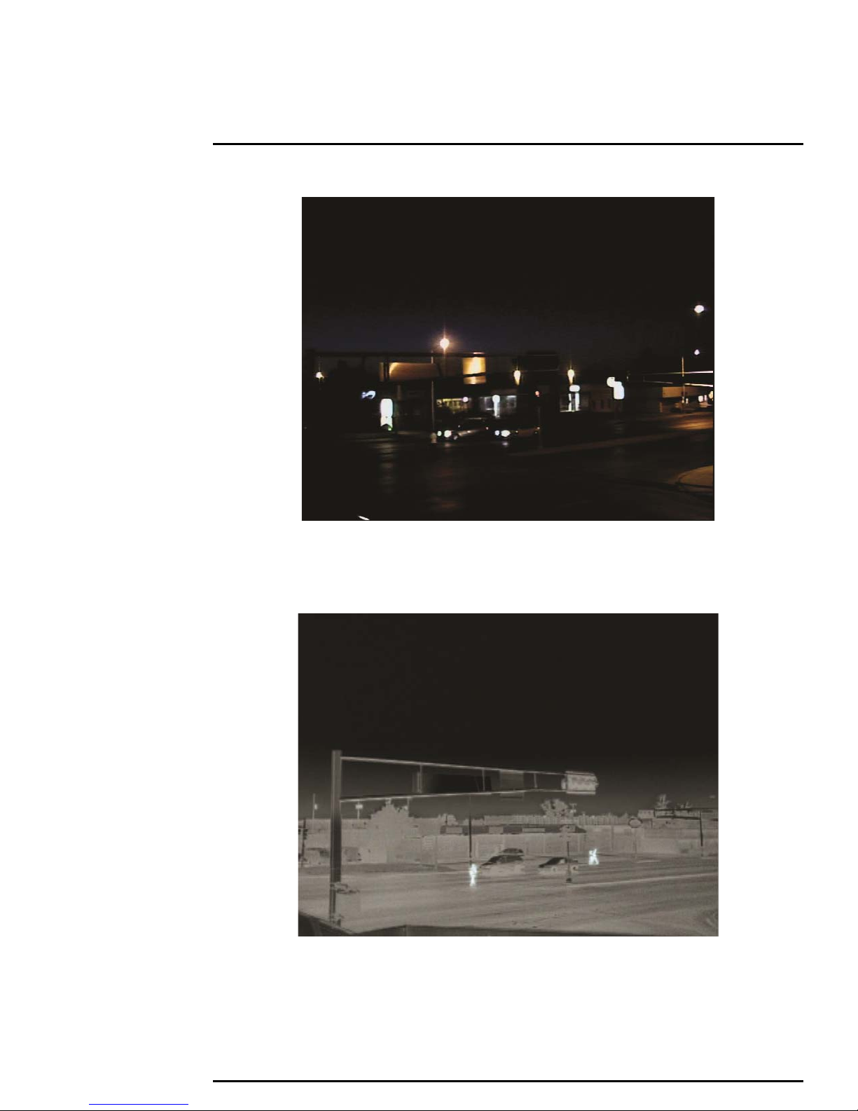
Figure 1: Image from a standard camera
Figure 2: Image from a thermal camera
427-0070-11-12, Rev. 100—FC-Series T Installation Manual, April 2012 iv

1 FC-Series T Camera Installation
1FC-Series T Camera Installation
This manual describes the installation of the FC-Series T cameras. If you need help during the
installation process, contact your local FLIR service representative or, call 877-773-3547 inside the US.
All installers and integrators are encouraged to take advantage of the training offered by FLIR; visit
http://www.flir.com/training for more information.
This manual includes the following topics:
• Installation overview
• Mounting the camera and its components
• Connecting the electronics
• Bench testing the camera
• Basic configuration and operation of the camera
• Camera Specifications
For safety, and to achieve the highest levels of performance from the FC-Series T camera system,
always follow the warnings and cautions in this manual when handling and operating the camera.
1.1 Warnings and Cautions
Warning!
If mounting the F-Series camera on a pole, tower or any elevated location, use industry standard safe
practices to avoid injuries.
Caution!
Except as described in this manual, do not open the FC-Series T camera for any reason. Damage to
the camera can occur as the result of careless handling or electrostatic discharge (ESD). Always
handle the camera with care to avoid damage to electrostatic-sensitive components.
Prior to making any connections, ensure the power supply or circuit breaker is switched off.
Be careful not to leave fingerprints on the FC-Series T camera’s infrared optics.
The FC-Series T camera requires a power supply of 90-240 VAC. Operating the camera outside of
the specified input voltage range or the specified operating temperature range can cause permanent
damage.
1.2 References
FLIR FC-Series T ICD, Doc # 427-00XX-XX-19 - The FC-Series T Interface Control Document (ICD),
available on the documentation CD or from the FLIR website, provides further details regarding
mechanical dimensions and mounting for the FC-Series T cameras. These documents are provided for
reference only.
NEMA Standards Publication TS 2-2003 v02.06 Traffic Controller Assemblies with NTCIP Requirements
UL 60950 Safety of Information Technology Equipment (ITE)
427-0070-11-12, version 100 April 2012 1-1

1
FC-Series T Camera Installation
1.3 Installation Overview
The FC-Series T Camera is an infrared thermal imaging camera intended for outdoor traffic
applications, and can be installed in a fixed location or on a pan/tilt mechanism.The FC-Series T
camera is intended to be mounted on a medium-duty fixed pedestal mount or wall mount commonly
used in the Traffic industry. Cables will exit from the back of the camera housing. The mount must
support up to 5 LBS (2.3 KG).
The camera requires a power connection and a video connection, both of which enter the camera via
conduit or a cable gland on the back of the camera. In order to access the electrical connections and
install the cables, it is necessary to temporarily remove the top cover of the camera housing. The
camera has an external ground connection on the outside back of the camera.
The power connects to a screw terminal block and the camera operates on 90-240 VAC single phase
50-60 Hz. The camera automatically adjusts to the input voltage - it is not necessary to set the input
voltage with a dip switch or other mechanism. The camera accepts an unterminated coax video
connection, which is clamped in place, or optionally a BNC-terminated video cable.
The FC-Series T is an analog camera and the video from the camera can be viewed over a traditional
analog video network. Analog video will require a connection to a video monitor or an analog video
matrix switch.
1.4 Installation Components
The FC-Series T camera includes these standard components:
• Fixed Camera Unit with sunshield and cable gland
• FC-Series T Camera Documentation Package
The installer will need to supply the following items (cable lengths are specific to the installation.)
• Electrical wire, for system power; (3-conductor, shielded, gauge determined by cable length and
supply voltage; Refer to paragraph 1.8.1 “Cable Gland Seal Inserts” on page 1-6 for additional
information)
• Camera grounding strap
• Coaxial RG59U video cables (unterminated cable at the camera end, or alternatively BNC
connector can be used) for analog video
•Camera mount
• Miscellaneous electrical hardware, connectors, and tools, including 3mm hex wrench (T-Handle),
small blade screwdriver, coax wire strip tool
1.5 Location Considerations
The camera will require connections for power and video. Ensure that cable distances do not exceed
the specifications and that cables adhere to all local and Industry Standards, Codes, and Best
Practices. The FC-Series T camera must be mounted upright, either on top of the mounting surface.
or underneath an overhanging mounting surface such as eaves or an awning. The unit should not be
mounted upside down.
Note
If the camera is to be mounted on a pole or tower or other hard-to-reach location, it may be a good
idea to connect and operate the camera as a bench test at ground level prior to mounting the camera
in its final location.
427-0070-11-12, version 100 April 2012 1-2
1
FC-Series T Camera Installation
1.5.1 Prior to Cutting/Drilling Holes
When selecting a mounting location for the FC-Series T camera, consider cable lengths and cable
routing. Ensure the cables are long enough, given the proposed mounting locations and cable routing
requirements, and route the cables before you install the components.
Use cables that have sufficient dimensions to ensure safety (for power cables) and adequate signal
strength (for video and communications). Allow space behind the camera so each cable does not
exceed its recommended minimum bend radius.
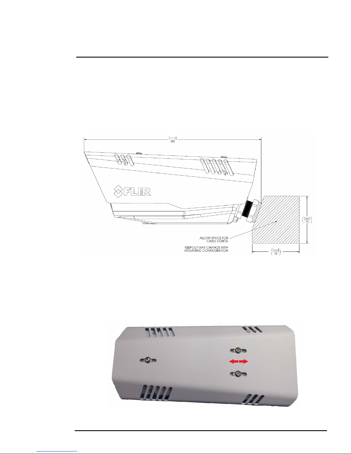
1.5.2 Sunshield
The camera includes a sunshield which should be used for any installation where the camera is
exposed to direct sunlight or precipitation, If the camera is mounted with the top mounting holes, the
sunshield is not used. Depending on the needs of the installation, the sunshield can be positioned in
the neutral (middle) position, or slightly forward or rearward.To change the position of the sunshield,
temporarily loosen the three 3mm hex screws on top, slide the sunshield forward or backward, and
retighten the screws.
427-0070-11-12, version 100 April 2012 1-3

1
Not to scale
Figure 1-1: FC-Series T Camera Mounting Holes
FC-Series T Camera Installation
1.6 Camera Mounting
The FC-Series T camera can be secured to the mount with two in-line 1/4-20 threaded fasteners on
the top or bottom of the camera. Alternatively the camera can be mounted with four M5 x 0.8 threaded
fasteners to the bottom of the camera. Use Loctite 222 low strength threadlocker for the top mount
fasteners (can be used with the bottom mount fasteners also). Refer to the FC-Series T ICD, FLIR
Doc. # 427-00XX-XX-19 for additional information and specific dimensions.
427-0070-11-12, version 100 April 2012 1-4

1
Not to scale
Figure 1-2: Top Side Mounting Holes
FC-Series T Camera Installation
Once the mounting location has been selected, verify both sides of the mounting surface are
accessible. Install the threaded fasteners into the camera with thread-locking compound.
1.7 Removing the Cover
The top cover of the camera is held in place with four 3mm hex screws. The screws are accessible
through slots in the sunshield, so the sunshield does not need to be removed from the top cover. Use
a 3 mm hex key to loosen the four captive screws, exposing the connections inside the camera
enclosure. There is a grounding wire connected inside the case to the top cover, as shown. If it (or any
of the grounding wires) is temporarily disconnected during the installation, it must be reconnected to
ensure proper grounding of the camera.
427-0070-11-12, version 100 April 2012 1-5

1
Cable Gland
FC-Series T Camera Installation
1.8 Cable Gland Sealing
Proper installation of cable sealing gland and use of appropriate elastomer inserts is critical to long
term reliability. Cables enter the camera mount enclosure through a liquid-tight compression gland.
Be sure to insert the cables through the cable gland on the enclosure before connecting them. If using
a BNC video connection, insert the cable through the gland before terminating the cable (terminated
connectors will not fit through the cable gland). Leave the gland nut loosened until all cable installation
has been completed, and ensure the manufacturer’s recommended cable bend radius is observed
within the enclosure. Do not forget to tighten the cable gland seal nut to ensure a watertight seal and
provide strain relief for cables.
1.8.1 Cable Gland Seal Inserts
The FC-Series T camera comes with a single 3/4” NPT cable gland installed in the camera, with a
two-hole gland seal insert. The gland includes a sealing washer and is secured to the camera with a
nut on the inside of the enclosure. The gland insert has one hole for the power cable (the larger hole)
and another for the video cable. Typically the power cable is inserted in the hole on the left and the
video is inserted through the right, so the cables line up with the connections inside the camera.
Table 1-1: Cable Min/Max Dimensions
Cable Minimum Maximum
Power cable (3 conductor) 6.8mm [ .27 IN ] 9.4 mm [ .37 IN ]
RG 59 Video cable 5.3 mm [ .21 IN ] 6.4 mm [ .25 IN ]
If non-standard cable diameters are used, an appropriate cable gland and insert should be used to fit
the desired cable and to fit the hole in the enclosure. FLIR Systems, Inc. does not provide cable gland
inserts other than the insert supplied with the system.
If a replacement is used, inspect and install the gland fitting in the back cover with suitable leak seal or
sealant and tighten to ensure water tight fittings. To fit the 1.05” (26.7mm) hole in the enclosure, the
thread size should be 3/4” NPT or M25. The gland should be installed with a sealing washer (for
example, Heyco p/n 3261 or equivalent) between the gland and the external surface of the enclosure.
427-0070-11-12, version 100 April 2012 1-6

1
Primary video
connection
Alternate video
connection
Not used
Power
connection
FC-Series T Camera Installation
1.9 Camera Connections
..
1.9.1 Connecting power
Prior to making any connections, ensure the power supply or circuit breaker is switched off. The
camera itself does not have an on/off switch. Generally the FC-Series T camera will be connected to a
circuit breaker and the circuit breaker will be used to apply or remove power to the camera. If power is
supplied to it, the camera will be powered on and operating.
The power cable supplied by the installer must use wires that are sufficient size gauge for the supply
voltage and length of the cable run, to ensure adequate current carrying capacity (18 AWG
recommended for most installations). Always follow local building/safety codes.
Refer to the diagram below for recommended dimensions for cable jacket and wire stripping.
Note
The terminal blocks for power connections will accept 16 AWG to 20 AWG wire size.
427-0070-11-12, version 100 April 2012 1-7

1
FC-Series T Camera Installation
1.9.2 Video Connection
The primary analog video connection of the camera is an open bare-wire connection that does not
require any crimping or termination. Alternatively, the camera also provides a BNC video connector.
Only one or the other connection should be used on a permanent basis to ensure adequate video
quality. The BNC connection can be used to temporarily monitor the video output, without
disconnecting the primary connection.
The video clamp connection is designed to be used with RG-59 solid center coax cable, such as
Belden part number 9244 or equivalent. The video cable used should be rated as RG-59/U or better
to ensure a quality video signal.
Note
Insert the cables through the cable glands on the enclosure before terminating and connecting them.
In general, terminated connectors will not fit through the cable gland. If a terminated cable is required,
it is possible to make a clean and singular cut in the gland seal to install the cable into the gland seal.
Strip the RG-59 cable similar to the way it would be prepared for a crimp-type BNC connector. This is
easily accomplished with a 3-level coaxial stripper that produces the correct stripped dimensions in
one operation, such as Ideal Industries Inc. Coaxial Stripper, part number 45-521 or equivalent.
427-0070-11-12, version 100 April 2012 1-8

1
Camera Ground
FC-Series T Camera Installation
1.9.3 Camera Grounding
Ensure the camera is properly grounded. Failure to properly ground the camera can lead to
permanent damage to the camera. Typical to good grounding practices, the camera chassis ground
should be connected to the lowest resistance path possible. The camera has an external ground
connection on the outside back of the camera.FLIR requires a grounding strap anchored to the
grounding lug and connected to the nearest earth-grounding point.
If, during installation, any ground connections inside the camera are disconnected, they should be
reconnected prior to closing the camera.
1.10 Bench Testing
If mounting the F-Series camera on a pole, tower or any elevated or difficult to access location, it may
be a good idea to bench test the camera prior to final installation. Connect the power and video, and
confirm the video can be displayed on a monitor when the power is turned on. Refer to section 2.1
“Troubleshooting Tips” on page 2-3 if there is a problem.
427-0070-11-12 Rev100 April 2012 1-9

1 FC-Series T Camera Installation
427-0070-11-12, version 100 April 2012 1-10

2Basic Operation
Splash Screen
2 Basic Operation
When power is applied to the FC-Series camera, a FLIR splash screen is displayed for less than two
seconds, and then the camera outputs the live video image. No operator action or intervention is
required - “power in, video out”. No configuration of the camera is necessary.
The thermal camera makes an image based on temperature differences. In the thermal image, the
hottest item in the scene appears as white and the coldest item is black, and all other items are
represented as a grey scale value between white and black.
It may take some time to get used to he thermal imagery from the camera, especially for someone who
only has experience with normal daylight cameras. Having a basic understanding of the differences
between thermal and daylight cameras can help with getting the best performance from the thermal
camera.
Both thermal and daylight cameras have detectors (pixels) that detect energy. One difference between
thermal and daylight cameras has to do with where the energy comes from to create an image. When
viewing an image with an ordinary camera, there has to be some source of visible light (something hot,
such as the sun or lights) that reflects off the objects in the scene to the camera. The same is true with
human eyesight; the vast majority of what people see is based on reflected light energy.
On the other hand, the thermal camera detects energy that is directly radiated from objects in the
scene. Most objects in typical surroundings are not hot enough to radiate visible light, but they easily
radiate the type of infrared energy that the thermal camera can detect. Even very cold objects, like ice
and snow, radiate this type of energy.
The camera is capable of sensing very small temperature differences, and produces a video image that
typically has dramatic contrast in comparison to daylight cameras. This high contrast level from the
thermal video enables intelligent video analytics software to perform more reliably.
427-0070-11-12, version 100 April 2012 2-1

2
Basic Operation
The performance of the camera will likely vary throughout the day. Right after sunset, objects warmed
by the sun will appear warmest. Early in the morning, many of these objects will appear cooler than
their surroundings, so be sure to look for subtle differences in the scene, as opposed to just hot
targets.
Originally developed for the military, thermal imaging cameras are now deployed in numerous
commercial applications where it is impractical or too expensive to use active illumination (lights).
They are perfect for a wide variety of applications including transportation, maritime, security, fire
fighting, and medical applications. The cameras often provide improved daytime viewing in
environments where traditional video camera performance suffers, such as in shadows or backlit
scenes.
The FC-Series T camera is a state-of-the-art thermal imaging system that will provide excellent night
visibility and situational awareness, without any form of natural or artificial illumination. The system is
easy to use, but it is useful to understand how to interpret what is displayed on the monitor.
While the imagery on the monitor may at first look similar to ordinary black and white daylight video,
experience with the camera in varying conditions and seasons will lead to an appreciation of the
characteristics that make thermal imaging distinct. A few tips on how to interpret some of the imagery
may help you to make the most of your system.
The thermal imager inside the camera does not sense light like conventional cameras; it senses heat
or temperature differences. Observe the system during daylight and nighttime operation, and notice
the differences in the picture quality, which are expected. The camera senses small “differences” in
apparent radiation from the objects in view, and displays them as either white (or lighter shades of
grey) for warmer objects, and black (or darker shades of grey) for colder objects.
The thermal imaging camera relies on the fact that all objects, even very cold objects like ice, emit
thermal energy in the portion of the infrared spectrum that this camera can "see", the long wave
infrared (LWIR). Therefore, unlike an illuminated infrared camera, a thermal imaging camera does not
need an additional active illumination source, and creates video based on directly radiated rather than
reflected energy.
This is why hot objects such as parts on an engines and exhaust pipes appear white, while the sky,
puddles of water and other cold objects appear dark (or cool). Scenes with familiar objects will be
easy to interpret with some experience. The camera automatically optimizes the image to provide you
with the best contrast in most conditions.
427-0070-11-12, version 100 April 2012 2-2

2
Basic Operation
2.1 Troubleshooting Tips
If you need help during the installation process, contact your local FLIR representative or, call 877773-3547 inside the US. FLIR Systems, Inc. offers a comprehensive selection of training courses to
help you to get the best performance and value from your thermal imaging camera. Find out more at
the FLIR training web page:
http://www.flir.com/training.
2.1.1 Image freezes momentarily
By design, the camera image will freeze momentarily on a periodic basis during the Flat Field
Correction (FFC) cycle (also known as Non-Uniformity Correction or NUC). Periodically the image will
momentarily freeze for a fraction of a second while the camera performs a flat field correction. A
shutter activates inside the camera and provides a target of uniform temperature, allowing the camera
to correct for ambient temperature changes and provide the best possible image. Just prior to the
FFC, a small green square will appear in the corner of the screen.
2.1.2 No video
If the camera will not produce an image, check the video connection at the camera and at your
display. If the connectors appear to be properly connected but the camera still does not produce an
image, ensure that power has been properly applied to the camera and the circuit breaker is set
properly. If a fuse was used, be sure the fuse is not blown. If the video cabling is suspected as a
possible source of the problem, plug a monitor into the BNC connection inside the camera and
determine if it produces an image.
When the camera is powered on, it will do a NUC operation shortly after startup. If you are uncertain if
the camera is receiving power, it may be useful to listen to the camera to hear if the click-click of the
shutter mechanism can be heard. It may be only be possible to perform this test when the camera is
on a work bench rather than in its installed position.
If the camera still does not produce an image, contact the FLIR dealer or reseller who provided the
camera, or contact FLIR directly (contact information is provided on the rear cover of this manual).
2.1.3 Noisy image
A noisy image is usually attributed to a cable problem (too long or inferior quality) or the cable is
picking up electromagnetic interference (EMI) from another device. Although coax cable has built-in
losses, the longer the cable is (or the smaller the wire gauge/thickness), the more severe the losses
become; and the higher the signal frequency, the more pronounced the losses. Unfortunately this is
one of the most common and unnecessary problems that plagues video systems in general.
Cable characteristics are determined by a number of factors (core material, dielectric material and
shield construction, among others) and must be carefully matched to the specific application.
Moreover, the transmission characteristics of the cable will be influenced by the physical environment
through which the cable is run and the method of installation. Use only high quality cable and ensure
the cable is suitable to the marine environment.
427-0070-11-12, version 100 April 2012 2-3

2
Images at night from standard camera (left) and thermal camera (right)
Basic Operation
Check cable connector terminations. Inferior quality connections may use multiple adapters which
can cause unacceptable noise. Use a high-quality video distribution amplifier when splitting the signal
to multiple monitors.
2.1.4 Image too dark or too light
By default the FC-Series T thermal camera uses an Automatic Gain Control (AGC) setting that has
proven to be superior for most applications, and the camera will respond to varying conditions
automatically. The installer should keep in mind that the sky is quite cold and can strongly affect the
overall image. It may be possible to solve this type of problem by slightly moving the camera up or
down to include (or exclude) items with hot or cold temperatures that influence the overall image. For
example, a very cold background (such as the sky) could cause the camera to use a wider
temperature range than appropriate.
2.1.5 Performance varies with time of day
You may observe differences in the way the camera performs at different times of the day, due to the
diurnal cycle of the sun. Recall that the camera produces an image based on temperature differences.
At certain times of the day, such as just before dawn, the objects in the image scene may all be
roughly the same temperature, compared to other times of the day. Compare this to imagery right
after sunset, when objects in the image may be radiating heat energy that has been absorbed during
the day due to solar loading. Greater temperature differences in the scene generally will allow the
camera to produce high-contrast imagery.
Performance may also be affected when objects in the scene are wet rather than dry, such as on a
foggy day or in the early morning when everything may be coated with dew. Under these conditions, it
may be difficult for the camera to show the temperature the object itself, rather than of the water
coating.
427-0070-11-12, version 100 April 2012 2-4

2
Basic Operation
2.1.6 Eastern or Western Exposure
Once installed, the camera may point directly east or west, and this may cause the sun to be in the
field of view during certain portions of the day. We do not recommend intentionally viewing the sun,
but looking at the sun will not permanently damage the sensor. In fact the thermal imaging camera
often provides a considerable advantage over a conventional camera in this type of back-lit situation.
However, the sun may introduce image artifacts that will eventually correct out. and it may take some
time for the camera to recover. The amount of time needed for recovery will depend on how long the
camera was exposed to the sun. The longer the exposure, the longer the recovery time needed.
427-0070-11-12, version 100 April 2012 2-5

2
Basic Operation
2.2 Camera specifications
Camera Model FC-Series T
Camera Platform Type Fixed
Composite Video NTSC or PAL (switch selectable)
Thermal Camera
Array Format 320x240 (NTSC), 3??x2?? (PAL)
Detector Type Long-Life, Uncooled VOx Microbolometer
Effective Resolution 76,800
Pixel Pitch 25 µm
Field Of View (Focal Length) FC-348 T = 48° × 37° (9 mm)
FC-334 T = 34° × 26° (13 mm)
FC-324 T = 24° × 18° (19 mm)
Spectral Range 7.5 to 13.5 μm
Lens Athermalized, focus-free
Ge n e r a l
Weight 4.2 lb with sun shield
Dimensions (L,W,H) 10.8" x 5.4" x 4.4" with sun shield
Input Voltage 90-240VAC single phase 50-60Hz
Power Consumption 1.7W nominal at 110VAC
18W Peak Power with heaters
Mounting Provisions Two 1/4-20" threaded holes on top and bottom,
1" spacing along center line front to back
Shipping weight 5.9 lbs (2.7kg) does this include the box, or ?
Shipping Dimensions 143/4”(L) x 73/4”(W) x 73/4”(H)
Environmental
IP rating IP66
Operating temperature range -50C to 75C (continuous operation)
-40C to 75C (cold start)
Storage Temperature range -55C to 85C
Humidity 0-95% relative
Shock MIL-STD-810F "Transportation"
Vibration 10g shock pulse with a 11ms half- sine profile
NEMA TS2 Tested in accordance with Section 2.1 of NEMA TS 2-
2003 for the following categories: Operating Voltage,
Operating Frequency, Ambient Temperature, Humidity,
Vibration & Shock
Approvals FCC Part15, Subpart B, Class B, EN 55022 Class B,
EN 50130 - 4, EN 50130-4
427-0070-11-12, version 100 April 2012 2-6

2Basic Operation
427-0070-11-12, version 100 April 2012 2-7

FLIR Systems, Inc.
70 Castilian Drive
Goleta, CA 93117
USA
PH: + 1 805.964.9797
PH: + 1 877.773.3547
(Sales)
PH: + 1 888.747.3547
(Support)
FX: + 1 805.685.2711
www.flir.com
Corporate Headquarters
FLIR Systems, Inc.
27700 SW Parkway Ave.
Wilsonville, OR 97070
USA
PH: +1 503.498.3547
FX: +1 503.498.3153
sales@flir.com
Document:
427-0070-11-12
Version: 100
Date: April 2012
 Loading...