

Page 1
User’s manual
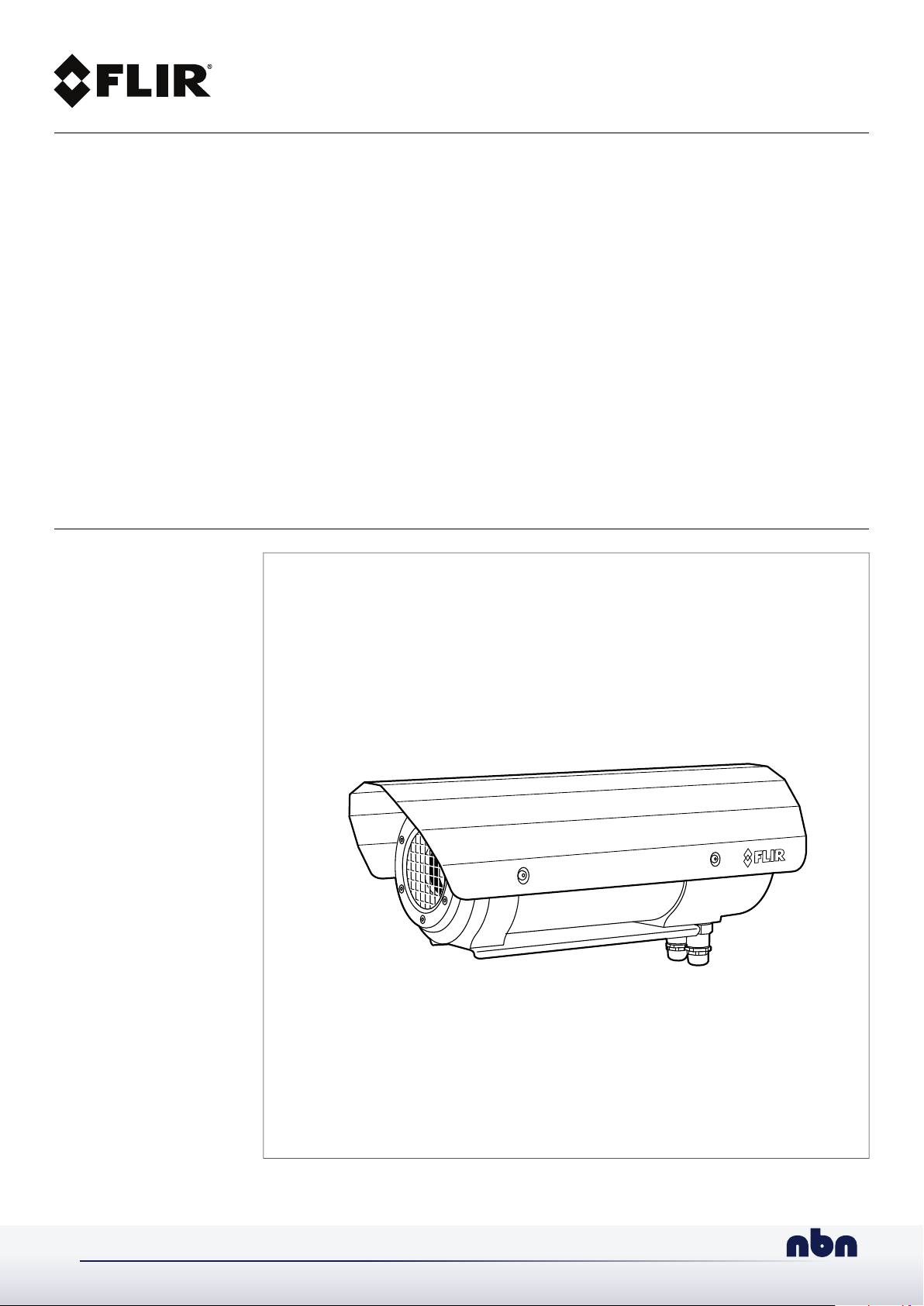
FLIR A310 ex
nbn Austria GmbH
Page 2

Page 3

User’s manual
FLIR A310 ex
#T559891; r. AE/57789/57789; en-US
iii
Page 4

Page 5

Table of contents
1 Disclaimers ............ .. ..................................... .. ................................. 1
1.1 Legal disclaimer ................................ .. .. .. ................................. 1
1.2 Usage statistics .......................... .. ..................................... ....... 1
1.3 U.S. Government Regulations....................... .. .. .. ......................... 1
1.4 Copyright ..... .. .. .. ................................. .. .. ................................ 1
1.5 Quality assurance .. .. .. .. ................................. .. .. .. ......................1
1.6 Patents...................... .. .. ................................. .. .. .. ..................1
1.7 EULA Terms ......... .. .. .. ................................. .. .. .. ......................1
1.8 EULA Terms ......... .. .. .. ................................. .. .. .. ......................1
2 Safety information .......... .. ..................................... .. ..........................2
3 Notice to user ......... .. ..................................... .. ................................. 3
3.1 Calibration................................. .. .. .. ................................. .. .. .. . 3
3.2 Accuracy ................ .. .. .. ................................. .. .. .. ................... 3
3.3 Disposal of electronic waste ............................... .. .. .. ................... 3
3.4 Training .... .. .. .. ................................. .. .. .. ................................. 3
3.5 Documentation updates .................................... .. .. .. ................... 3
3.6 Important note about this manual........... .. .. .. ................................. 4
3.7 Note about authoritative versions. .. ................................... .. .. ........4
4 Customer help .............. .. .. .. ............................... .. .. .. ......................... 5
4.1 General ............... .. .. .. ................................. .. .. .. ......................5
4.2 Submitting a question .............. .. .. .. ................................. .. .. ....... 5
4.3 Downloads ........... .. .. .. ................................. .. .. .. ......................5
5 What is FLIR A310 ex?..................................... .. ................................. 6
6 Typical system overview.......................... ..................................... .. ....7
7 Typical system setup procedure................ .. .. .. ................................. .. .8
8 Technical data ..... .. .. .. ................................. .. .. .. ................................. 9
8.1 Online field-of-view calculator ............ .. .. .. ................................. .. . 9
8.2 Note about technical data . ................................. .. .. .. ................... 9
8.3 Note about authoritative versions. .. ................................... .. .. ........9
8.4 FLIR A310 ex 25°.......... .. .. .. ................................. .. .. .. ............. 10
8.5 FLIR A310 ex 45°.......... .. .. .. ................................. .. .. .. ............. 14
9 Mechanical drawings .. .. ..................................... .............................. 18
10 EC Type Examination Certificate........................... .. ........................... 20
11 EC Type Examination Certificate, 1st supplement................................ 23
12 EC Type Examination Certificate, 2nd supplement. .............................. 26
13 EC Type Examination Certificate, 3rd supplement . .............................. 28
14 EC Declaration of conformity (enclosure) ..................... .. .................... 31
15 Certiticate of conformity (camera) ..... ....................................... ......... 33
16 Thermographic measurement techniques .............................. .. .......... 35
16.1 Introduction .. .. .. .. ................................. .. .. .. ........................... 35
16.2 Emissivity....................... .. .. .. ................................. .. .. .. .......... 35
16.2.1 Finding the emissivity of a sample. ............................... .. .. 35
16.3 Reflected apparent temperature ......... .. .. .. ................................. . 39
16.4 Distance .. ................................. .. .. .. ................................. .. .. . 39
16.5 Relative humidity ... .. .. .. ................................. .. .. .. .................... 39
16.6 Other parameters............. .. .. .. ................................. .. .. .. .......... 39
17 About FLIR Systems .................. .. ..................................... .. ............. 40
17.1 More than just an infrared camera ............. .. .. .. ........................... 41
17.2 Sharing our knowledge ............. .. .. .. ................................. .. .. .. .. 41
17.3 Supporting our customers........................... .............................. 42
A OEM manual (German)....... .. .. .. ................................. .. .. .. ................. 43
B OEM manual (English) ....... .. ..................................... ....................... 67
#T559891; r. AE/57789/57789; en-US
v
Page 6

Page 7

1
Disclaimers
1.1 Legal disclaimer
For warranty terms, please refer to https://www.flir.com/warranty.
1.2 Usage statistics
FLIR Systems reserves the right to gather anonymous usage statistics to help
maintain and improve the quality of our software and services.
1.3 U.S. Government Regulations
This product may be subject to U.S. Export Regulations. Please send any inquiries to exportquestions@flir.com.
1.4 Copyright
© 2019, FLIR Systems, Inc. All rights reserved worldwide. No parts of the
software including source code may be reproduced, transmitted, transcribed
or translated into any language or computer language in any form or by any
means, electronic, magnetic, optical, manual or otherwise, without the prior
written permission of FLIR Systems.
The documentation must not, in whole or part, be copied, photocopied, reproduced, translated or transmitted to any electronic medium or machine
readable form without prior consent, in writing, from FLIR Systems.
Names and marks appearing on the products herein are either registered
trademarks or trademarks of FLIR Systems and/or its subsidiaries. All other
trademarks, trade names or company names referenced herein are used for
identification only and are the property of their respective owners.
1.5 Quality assurance
The Quality Management System under which these products are developed
and manufactured has been certified in accordance with the ISO 9001
standard.
FLIR Systems is committed to a policy of continuous development; therefore
we reserve the right to make changes and improvements on any of the products without prior notice.
1.6 Patents
This product is protected by patents, design patents, patents pending, or design patents pending. Please refer to the FLIR Systems’ patent registry:
https://www.flir.com/patentnotices.
1.7 EULA Terms
Qt4 Core and Qt4 GUI, Copyright ©2013 Nokia Corporation and FLIR Systems AB. This Qt library is a free software; you can redistribute it and/or modify it under the terms of the GNU Lesser General Public License as published
by the Free Software Foundation; either version 2.1 of the License, or (at your
option) any later version. This library is distributed in the hope that it will be
useful, but WITHOUT ANY WARRANTY; without even the implied warranty of
MERCHANTABILITYor FITNESS FOR A PARTICULAR PURPOSE. See the
GNU Lesser General Public License, http://www.gnu.org/licenses/lgpl-2.1.
html. The source code for the libraries Qt4 Core and Qt4 GUI may be requested from FLIR Systems AB.
1.8 EULA Terms
• Youhave acquired a device (“INFRARED CAMERA”) that includes software licensed by FLIR Systems AB from Microsoft Licensing, GP or its
affiliates (“MS”). Those installed software products of MS origin, as well
as associated media, printed materials, and “online” or electronic documentation (“SOFTWARE”) are protected by international intellectual
property laws and treaties. The SOFTWARE is licensed, not sold. All
rights reserved.
• IF YOU DO NOT AGREE TO THIS END USER LICENSE AGREEMENT
(“EULA”), DO NOT USE THE DEVICE OR COPY THE SOFTWARE. INSTEAD, PROMPTLY CONTACT FLIR Systems AB FOR INSTRUCTIONS ON RETURN OF THE UNUSED DEVICE(S) FOR A REFUND.
ANY USE OF THE SOFTWARE, INCLUDING BUT NOT LIMITED TO
USE ON THE DEVICE, WILL CONSTITUTE YOUR AGREEMENT TO
THIS EULA (OR RATIFICATION OF ANY PREVIOUS CONSENT).
• GRANT OF SOFTWARE LICENSE. This EULA grants you the following
license:
◦ Youmay use the SOFTWARE only on the DEVICE.
◦ NOT FAULT TOLERANT. THE SOFTWARE IS NOT FAULT TOL-
ERANT.FLIR Systems AB HAS INDEPENDENTLY DETERMINED
HOW TO USE THE SOFTWARE IN THE DEVICE, AND MS HAS
RELIED UPON FLIR Systems AB TO CONDUCT SUFFICIENT
TESTING TO DETERMINE THAT THE SOFTWARE IS SUITABLE
FOR SUCH USE.
◦ NO WARRANTIES FOR THE SOFTWARE. THE SOFTWARE is
provided “AS IS” and with all faults. THE ENTIRE RISK AS TO
SATISFACTORY QUALITY, PERFORMANCE, ACCURACY, AND
EFFORT (INCLUDING LACK OF NEGLIGENCE) IS WITH YOU.
ALSO, THERE IS NO WARRANTYAGAINST INTERFERENCE
WITH YOUR ENJOYMENT OF THE SOFTWARE OR AGAINST
INFRINGEMENT.IF YOU HAVE RECEIVED ANY WARRANTIES
REGARDING THE DEVICE OR THE SOFTWARE, THOSE WARRANTIES DO NOT ORIGINATE FROM, AND ARE NOT BINDING
ON, MS.
◦ No Liability for Certain Damages. EXCEPT AS PROHIBITED BY
LAW,MS SHALL HAVE NO LIABILITY FOR ANY INDIRECT,
SPECIAL, CONSEQUENTIAL OR INCIDENTAL DAMAGES
ARISING FROM OR IN CONNECTION WITH THE USE OR PERFORMANCE OF THE SOFTWARE. THIS LIMITATION SHALL
APPLYEVEN IF ANY REMEDY FAILS OF ITS ESSENTIAL PURPOSE. IN NO EVENT SHALL MS BE LIABLE FOR ANY
AMOUNT IN EXCESS OF U.S. TWO HUNDRED FIFTY DOLLARS (U.S.$250.00).
◦ Limitations on Reverse Engineering, Decompilation, and Dis-
assembly. You may not reverse engineer, decompile, or disas-
semble the SOFTWARE, except and only to the extent that such
activity is expressly permitted by applicable law notwithstanding
this limitation.
◦ SOFTWARE TRANSFER ALLOWED BUT WITH RESTRIC-
TIONS. You may permanently transfer rights under this EULA only
as part of a permanent sale or transfer of the Device, and only if
the recipient agrees to this EULA. If the SOFTWARE is an upgrade,
any transfer must also include all prior versions of the SOFTWARE.
◦ EXPORT RESTRICTIONS. You acknowledge that SOFTWARE is
subject to U.S. export jurisdiction. You agree to comply with all applicable international and national laws that apply to the SOFTWARE, including the U.S. Export Administration Regulations, as
well as end-user, end-use and destination restrictions issued by U.
S. and other governments. For additional information see http://
www.microsoft.com/exporting/.
#T559891; r. AE/57789/57789; en-US
1
Page 8
2
Safety information
CAUTION
Do not point the infrared camera (with or without the lens cover) at strong energy sources, for example,
devices that cause laser radiation, or the sun. This can have an unwanted effect on the accuracy of the
camera. It can also cause damage to the detector in the camera.
CAUTION
Applicability: Cameras with an automatic shutter that can be disabled.
Do not disable the automatic shutter in the camera for a long time period (a maximum of 30 minutes is
typical). If you disable the shutter for a longer time period, damage to the detector can occur.
#T559891; r. AE/57789/57789; en-US
2
Page 9
3
Notice to user
3.1 Calibration
We recommend that you send in the camera for calibration once a year. Contact your local sales office for instructions on where to send the camera.
3.2 Accuracy
For very accurate results, we recommend that you wait 5 minutes after you have started
the camera before measuring a temperature.
3.3 Disposal of electronic waste
Electrical and electronic equipment (EEE) contains materials, components and substances that may be hazardous and present a risk to human health and the environment
when waste electrical and electronic equipment (WEEE) is not handled correctly.
Equipment marked with the below crossed-out wheeled bin is electrical and electronic
equipment. The crossed-out wheeled bin symbol indicates that waste electrical and electronic equipment should not be discarded together with unseparated household waste,
but must be collected separately.
For this purpose all local authorities have established collection schemes under which
residents can dispose waste electrical and electronic equipment at a recycling centre or
other collection points, or WEEE will be collected directly from households. More detailed information is available from the technical administration of the relevant local
authority.
3.4 Training
To read about infrared training, visit:
• http://www.infraredtraining.com
• http://www.irtraining.com
• http://www.irtraining.eu
3.5 Documentation updates
Our manuals are updated several times per year, and we also issue product-critical notifications of changes on a regular basis.
To access the latest manuals, translations of manuals, and notifications, go to the Download tab at:
http://support.flir.com
It only takes a few minutes to register online. In the download area you will also find the
latest releases of manuals for our other products, as well as manuals for our historical
and obsolete products.
#T559891; r. AE/57789/57789; en-US
3
Page 10

Notice to user3
3.6 Important note about this manual
FLIR Systems issues generic manuals that cover several cameras within a model line.
This means that this manual may contain descriptions and explanations that do not apply
to your particular camera model.
3.7 Note about authoritative versions
The authoritative version of this publication is English. In the event of divergences due to
translation errors, the English text has precedence.
Any late changes are first implemented in English.
#T559891; r. AE/57789/57789; en-US
4
Page 11

4
Customer help
4.1 General
For customer help, visit:
http://support.flir.com
4.2 Submitting a question
To submit a question to the customer help team, you must be a registered user. It only
takes a few minutes to register online. If you only want to search the knowledgebase for
existing questions and answers, you do not need to be a registered user.
When you want to submit a question, make sure that you have the following information
to hand:
• The camera model
• The camera serial number
• The communication protocol, or method, between the camera and your device (for example, SD card reader, HDMI, Ethernet, USB, or FireWire)
• Device type (PC/Mac/iPhone/iPad/Android device, etc.)
• Version of any programs from FLIR Systems
• Full name, publication number, and revision number of the manual
4.3 Downloads
On the customer help site you can also download the following, when applicable for the
product:
• Firmware updates for your infrared camera.
• Program updates for your PC/Mac software.
• Freeware and evaluation versions of PC/Mac software.
• User documentation for current, obsolete, and historical products.
• Mechanical drawings (in *.dxf and *.pdf format).
• Cad data models (in *.stp format).
• Application stories.
• Technical datasheets.
#T559891; r. AE/57789/57789; en-US
5
Page 12
5
What is FLIR A310 ex?
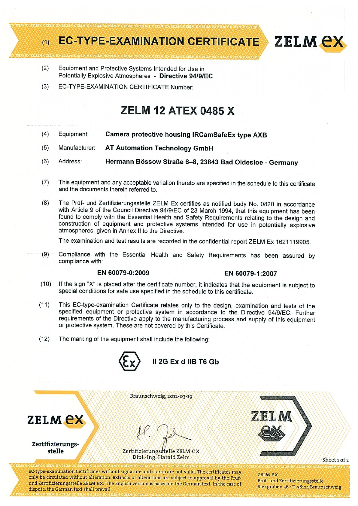
Explosive atmospheres need to be protected from ignition sources by selecting equipment and protective systems that meet the requirements of the ATEX product directives
and similar regulations.
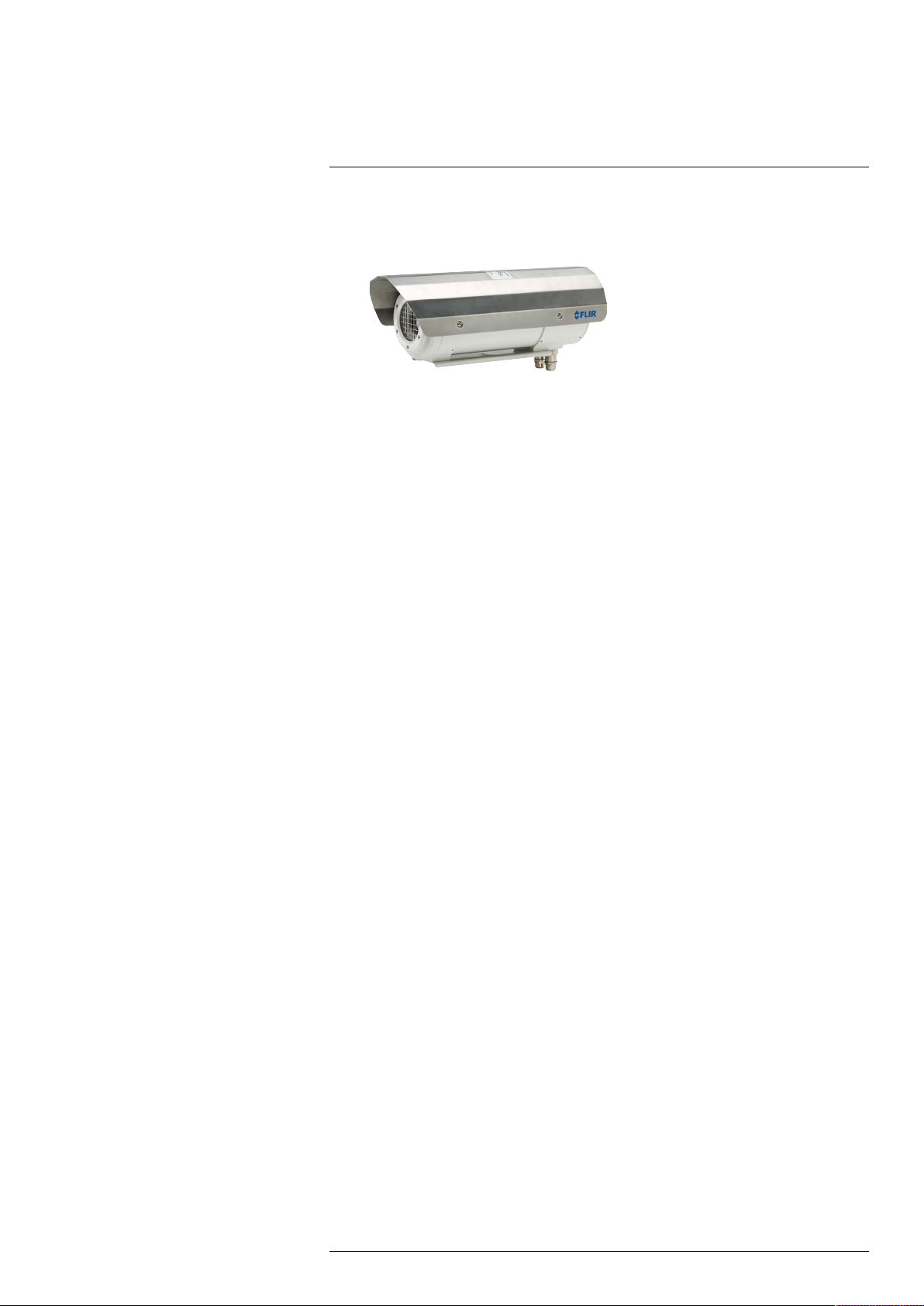
The FLIR A310 ex is an ATEX-proof solution, with a thermal imaging camera mounted in
an enclosure, making it possible to monitor critical and other valuable assets in explosive
atmospheres. Process monitoring, quality control, and fire detection in potentially explosive locations are typical applications for the FLIR A310 ex.
Key features:
• Thermography monitoring and early fire detection in explosion hazard areas.
• Enclosures for infrared cameras in classification zones 1, 2, 21, and 22.
• ATEX certified to the latest standards.
• Rated to protection class IP67.
• Plug and play installation, with the enclosure delivered ready for use.
#T559891; r. AE/57789/57789; en-US
6
Page 13
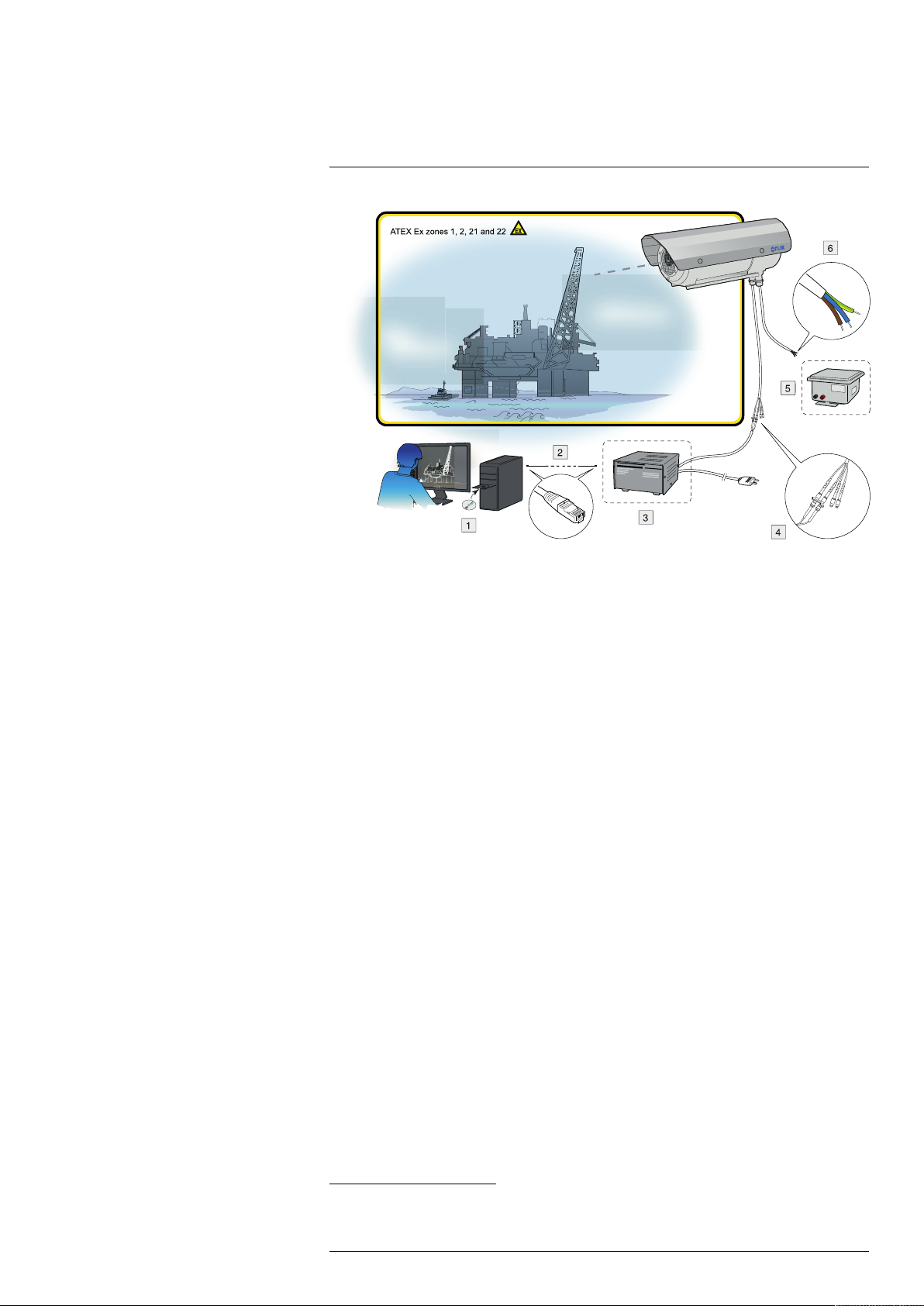
6
Typical system overview
1. Thermovision System Tools & Utilities CD-ROM.
2. Ethernet cable.
3. Optical-to-Ethernet converter.
4. FC connectors from the camera housing (including two spares).
5. 24 V DC power supply.
6. Pigtail cable from the housing. The color coding of the pigtail cable is:
• Brown: positive (+).
• Blue: negative (–).
• Green/yellow: earth.
1
1
1
1. Not supplied with the camera unit.
#T559891; r. AE/57789/57789; en-US
7
Page 14

7
Typical system setup procedure
1. Unpack the camera unit from the cardboard box.
2. Install the camera unit at the intended location. It is the responsibility of the installer
to meet all applicable safety standards required by the authorities of the region in
which the unit will be operating in.
3. Connect the camera unit to an external power supply.
The color coding of the pigtail cable is:
• Brown: positive +.
• Blue: negative –.
• Green/yellow: earth.
Note The external power supply must not be inside the classified zone.
4. Connect the camera unit to an optical-to-Ethernet converter.
Note The optical-to-Ethernet converter must not be inside the classified zone.
5. Install the Thermovision System Tools & Utilities CD-ROM on a computer connected
to the network. This will install the following software:
• FLIR IP Config.
• FLIR IR Monitor.
• FLIR IR Camera Player.
6. Start FLIR IP Config to identify the unit in the network and automatically assign or
manually set IP addresses, etc. For more information, see the FLIR IP Config manual
on the User Documentation CD-ROM or on the Help menu in FLIR IP Config.
7. Start FLIR IR Monitor to control the camera, e.g., laying out measurement tools and
setting up alarms. For more information, see the FLIR IR Monitor manual on the User
Documentation CD-ROM or on the Help menu in FLIR IR Monitor.
2
The unit requires 24 V DC in.
2
2. Not supplied with the camera unit.
#T559891; r. AE/57789/57789; en-US
8
Page 15

8
Technical data
Table of contents
8.1 Online field-of-view calculator.......................... .. ................................. 9
8.2 Note about technical data................. ....................................... ...........9
8.3 Note about authoritative versions.............. .. ..................................... .. .9
8.4 FLIR A310 ex 25° .................. ..................................... .. .................... 10
8.5 FLIR A310 ex 45° .................. ..................................... .. .................... 14
8.1 Online field-of-view calculator
Please visit http://support.flir.com and click the photo of the camera series for field-of-
view tables for all lens–camera combinations.
8.2 Note about technical data
FLIR Systems reserves the right to change specifications at any time without prior notice.
Please check http://support.flir.com for latest changes.
8.3 Note about authoritative versions
The authoritative version of this publication is English. In the event of divergences due to
translation errors, the English text has precedence.
Any late changes are first implemented in English.
#T559891; r. AE/57789/57789; en-US
9
Page 16

Technical data8
8.4 FLIR A310 ex 25°
P/N: 71001-1103
Rev.: 51350
Introduction
The FLIR A310 ex is an ATEX-proof solution, with a thermal imaging camera mounted in
an enclosure—making it possible to monitor critical and other valuable assets in explosive atmospheres. Process monitoring, quality control, and fire detection in potentially
explosive locations are typical applications for the FLIR A310 ex.
• Thermographic monitoring and early fire detection in an explosion–hazard area.
• Enclosures for infrared cameras in Ex zones 1, 2, 21, 22.
• ATEX certified.
• Protection class IP67.
• Plug-and-play installation with the enclosure delivered ready for use.
• Available with additional options.
The certification covers the entire system, which includes the enclosure as well as all
components inside of it, such as the infrared camera, heater, and integrated controller.
This means that no additional certification is required for operation.
The integrated controller is equipped with two fiber optic and two Ethernet ports. This enables a flexible network integration in star ring topologies.
In addition, the integrated controller features several digital I/O channels and sensors for
temperature, humidity, and pressure. Among other functions, the I/O channels enable
the user to switch on/off the camera and the heater via remote control. Access is through
an integrated web interface or Modbus TCP/IP.
Explosion-proof housing
General data
Ambient temperature range for operation –40°C to +60°C (–40°F to +140°F)
Protection class IP67
Weight 6.7 kg (without camera and lens)
Empty volume 5.06 l
External dimensions (without sun shield) D = 170 mm, L = 408 mm
Housing material Nickel-plated aluminium
Surface
Protection window Germanium, double-sided AR Coated, externally
Maximum power of the additional heater 16 W
Operating voltage 24 V DC
Maximum electric connection power 60 W
Power cable Helukabel 37264
Length of power cable 4 m (13 ft.)
Power cable configuration Pigtail
Powder coated
with additional hard-carbon layer
Ethernet medium Multi-mode breakout fiber AT-V(ZN)Y(ZN)Y 4G50/
125 OM2
Length of Ethernet cable 4 m (13 ft.)
Ethernet configuration Pigtail with FC connector
#T559891; r. AE/57789/57789; en-US
10
Page 17

Technical data8
Explosion protection-specific data
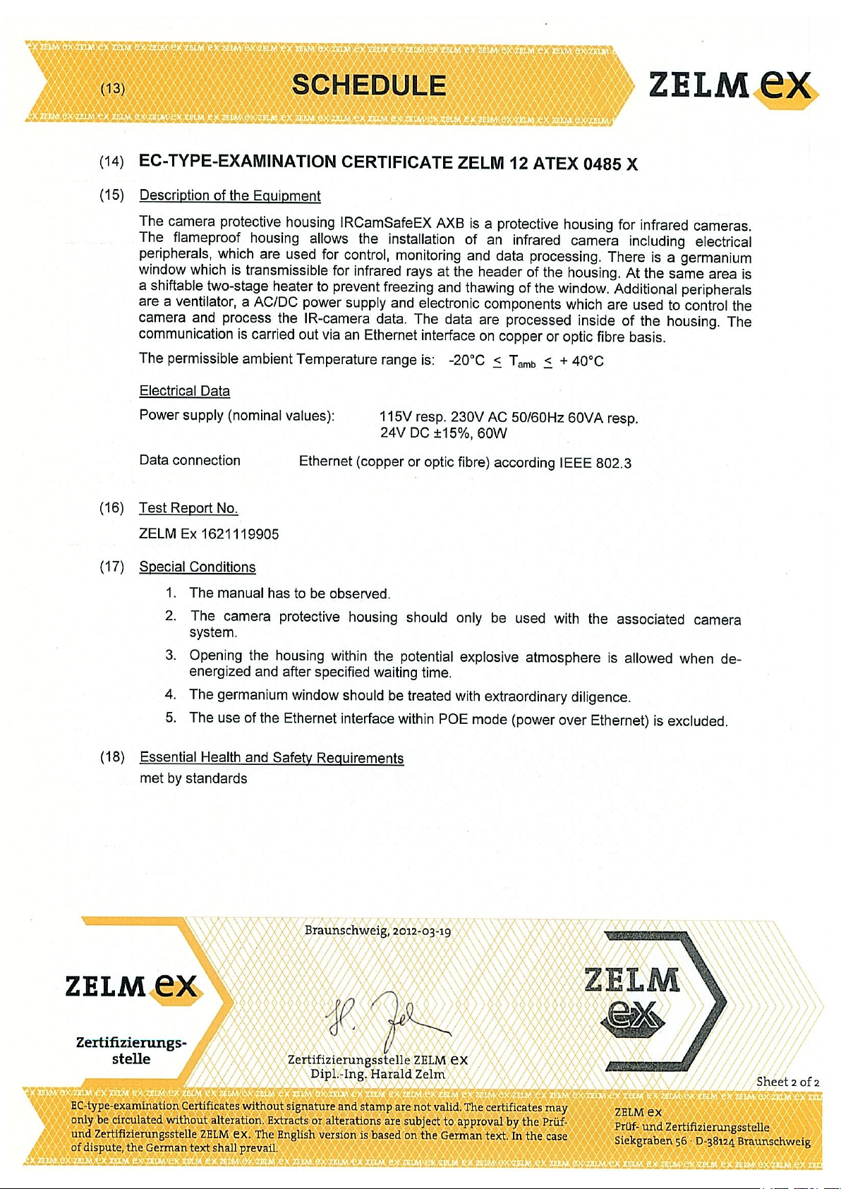
For use in EX zone 1, 2, 21, 22
Ignition protection category Flame-proof enclosure “d”
Maximum surface temperature (according to temperature class T6)
ATEX certification (version -AXC)
Verification certificate ZELM 12 ATEX 0485 X
Maximum 85°C
• II 2G Ex db IIC T6 / T5
• II 2D Ex tb IIIC T85° / T100
Camera system
Imaging and optical data
IR resolution 320 × 240 pixels
Thermal sensitivity/NETD < 0.05°C @ +30°C (+86°F) / 50 mK
Field of view (FOV)
Minimum focus distance 0.4 m (1.31 ft.)
Focal length 18 mm (0.7 in.)
Spatial resolution (IFOV)
Lens identification Automatic
F-number 1.3
Image frequency 30 Hz
Focus Automatic or manual (built in motor)
Zoom 1–8× continuous, digital, interpolating zooming on
25° × 18.8°
1.36 mrad
images
Detector data
Detector type Focal plane array (FPA), uncooled
Spectral range
Detector pitch 25 µm
Detector time constant Typical 12 ms
Measurement
Object temperature range
Accuracy ±4°C (±7.2°F) or ±4% of reading
Measurement analysis
Spotmeter 10 (with no image streaming)
Area 10 boxes with max./min./average/position (with no
Isotherm 1 with above/below/interval
Measurement option Measurement Mask Filter
Difference temperature Delta temperature between measurement func-
Reference temperature Manually set or captured from any measurement
Atmospheric transmission correction Automatic, based on inputs for distance, atmos-
Optics transmission correction Automatic, based on signals from internal sensors
microbolometer
7.5–13 µm
• –20 to +120°C (–4 to +248°F)
• 0 to +350°C (+32 to +662°F)
image streaming)
Schedule response: File sending (ftp), email
(SMTP)
tions or reference temperature
function
pheric temperature and relative humidity
#T559891; r. AE/57789/57789; en-US
11
Page 18

Technical data8
Measurement analysis
Emissivity correction Variable from 0.01 to 1.0
Reflected apparent temperature correction Automatic, based on input of reflected
External optics/windows correction Automatic, based on input of optics/window trans-
Measurement corrections Global and individual object parameters
Alarm
Alarm functions 6 automatic alarms on any selected measurement
Alarm output Log, store image, file sending (ftp), email notifica-
temperature
mission and temperature
function, Digital In, Camera temperature, timer
tion (SMTP).
With an additional FLIR I/O module (T130090 or
T130091), the system can provide up to 8 digital
outputs and 8 analog outputs that can be connected to any camera analytic function or the
cameras status. These outputs can be connected
to existing alarm infrastructure, PLCs, or data
loggers.
Set-up
Color palettes Color palettes (BW, BW inv, Iron, Rain)
Set-up commands Date/time, Temperature (°C/°F)
Storage of images
Storage media Built-in memory for image storage
File formats Standard JPEG, 16-bit measurement data
Ethernet
Ethernet
Ethernet, type 100 Mbps
Ethernet, standard IEEE 802.3
Ethernet, configuration Pigtail with FC-connector (fiber)
Ethernet, communication TCP/IP socket-based FLIR proprietary
Ethernet, video streaming
Ethernet, image streaming 16-bit 320 × 240 pixels @ 7-8 Hz
Ethernet, protocols
Shipping information
Packaging, type
List of contents
Packaging, weight
Packaging, size 495 × 370 × 192 mm (19.5 × 14.6 × 7.6 in.)
EAN-13 7332558008355
UPC-12
Country of origin Sweden
included
Control, result and image
MPEG-4, ISO/IEC 14496-1 MPEG-4 ASP@L5
• Radiometric
Ethernet/IP, Modbus TCP, TCP, UDP, SNTP, RTSP,
RTP, HTTP, ICMP, IGMP, ftp, SMTP, SMB (CIFS),
DHCP, MDNS (Bonjour), uPnP
Cardboard box
• Infrared camera with lens, in explosion-proof
housing
• Printed documentation
• Utility CD-ROM
845188008703
#T559891; r. AE/57789/57789; en-US
12
Page 19

Technical data8
Supplies & accessories:
• T129252; Special temperature range -20 to +700 deg C
• T129253; Special temperature range -20 to +500 deg C
• T129254; High temperature measurement option -20 to +2000 deg C
• T130151; Special temperature range -20 to +2000 deg C
• T130090; I/O module MIO-A310-1
• T130091; I/O module MIO-A310-7
• T911288ACC; Pole mount adapter for wall mount kit
• T199713; ThermoVision CM Panel, max. 4 cameras
• T199712; ThermoVision CM Panel, max. 9 cameras
• T130169; Thermovision CM, max. 4 cameras
• T130170; Thermovision CM, max. 9 cameras
• T911263ACC; Wall mount kit
• INST-EW-0165; Extended Warranty 1 Year for A6xx, A310ex, T640/bx, T650sc, T660
• INST-EWGM-0175; Premium Service Package for A310ex, A3xxf, A6xx, T620-T660
• INST-GM-0155; General Maintenance Package for A3xxf, A310ex, A310pt, A6xx
#T559891; r. AE/57789/57789; en-US
13
Page 20
Technical data8
8.5 FLIR A310 ex 45°
P/N: 71001-1104
Rev.: 51351
Introduction
The FLIR A310 ex is an ATEX-proof solution, with a thermal imaging camera mounted in
an enclosure—making it possible to monitor critical and other valuable assets in explosive atmospheres. Process monitoring, quality control, and fire detection in potentially
explosive locations are typical applications for the FLIR A310 ex.
• Thermographic monitoring and early fire detection in an explosion–hazard area.
• Enclosures for infrared cameras in Ex zones 1, 2, 21, 22.
• ATEX certified.
• Protection class IP67.
• Plug-and-play installation with the enclosure delivered ready for use.
• Available with additional options.
The certification covers the entire system, which includes the enclosure as well as all
components inside of it, such as the infrared camera, heater, and integrated controller.
This means that no additional certification is required for operation.
The integrated controller is equipped with two fiber optic and two Ethernet ports. This enables a flexible network integration in star ring topologies.
In addition, the integrated controller features several digital I/O channels and sensors for
temperature, humidity, and pressure. Among other functions, the I/O channels enable
the user to switch on/off the camera and the heater via remote control. Access is through
an integrated web interface or Modbus TCP/IP.
Explosion-proof housing
General data
Ambient temperature range for operation –40°C to +60°C (–40°F to +140°F)
Protection class IP67
Weight 6.7 kg (without camera and lens)
Empty volume 5.06 l
External dimensions (without sun shield) D = 170 mm, L = 408 mm
Housing material Nickel-plated aluminium
Surface
Protection window Germanium, double-sided AR Coated, externally
Maximum power of the additional heater 16 W
Operating voltage 24 V DC
Maximum electric connection power 60 W
Power cable Helukabel 37264
Length of power cable 4 m (13 ft.)
Power cable configuration Pigtail
Ethernet medium
Length of Ethernet cable 4 m (13 ft.)
Ethernet configuration Pigtail with FC connector
Powder coated
with additional hard-carbon layer
Multi-mode breakout fiber AT-V(ZN)Y(ZN)Y 4G50/
125 OM2
#T559891; r. AE/57789/57789; en-US
14
Page 21

Technical data8
Explosion protection-specific data
For use in EX zone 1, 2, 21, 22.
Ignition protection category Flame-proof enclosure “d”
Maximum surface temperature (according to temperature class T6)
ATEX certification (version -AXC)
Verification certificate ZELM 12 ATEX 0485 X
Maximum 85°C
• II 2G Ex db IIC T6 / T5
• II 2D Ex tb IIIC T85° / T100
Camera system
Imaging and optical data
IR resolution 320 × 240 pixels
Thermal sensitivity/NETD < 0.05°C @ +30°C (+86°F) / 50 mK
Field of view (FOV)
Minimum focus distance 0.20 m (0.66 ft.)
Focal length 9.66 mm (0.38 in.)
Spatial resolution (IFOV)
Lens identification Automatic
F-number 1.3
Image frequency 30 Hz
Focus Automatic or manual (built in motor)
Zoom 1–8× continuous, digital, interpolating zooming on
45° × 33.8
2.59 mrad
images
Detector data
Detector type Focal plane array (FPA), uncooled
Spectral range
Detector pitch 25 µm
Detector time constant Typical 12 ms
Measurement
Object temperature range
Accuracy ±4°C (±7.2°F) or ±4% of reading
Measurement analysis
Spotmeter 10 (with no image streaming)
Area 10 boxes with max./min./average/position (with no
Isotherm 1 with above/below/interval
Measurement option Measurement Mask Filter
Difference temperature Delta temperature between measurement func-
Reference temperature Manually set or captured from any measurement
Atmospheric transmission correction Automatic, based on inputs for distance, atmos-
Optics transmission correction Automatic, based on signals from internal sensors
microbolometer
7.5–13 µm
• –20 to +120°C (–4 to +248°F)
• 0 to +350°C (+32 to +662°F)
image streaming)
Schedule response: File sending (ftp), email
(SMTP)
tions or reference temperature
function
pheric temperature and relative humidity
#T559891; r. AE/57789/57789; en-US
15
Page 22
Technical data8
Measurement analysis
Emissivity correction Variable from 0.01 to 1.0
Reflected apparent temperature correction Automatic, based on input of reflected
External optics/windows correction Automatic, based on input of optics/window trans-
Measurement corrections Global and individual object parameters
Alarm
Alarm functions 6 automatic alarms on any selected measurement
Alarm output Log, store image, file sending (ftp), email notifica-
temperature
mission and temperature
function, Digital In, Camera temperature, timer
tion (SMTP).
With an additional FLIR I/O module (T130090 or
T130091), the system can provide up to 8 digital
outputs and 8 analog outputs that can be connected to any camera analytic function or the
cameras status. These outputs can be connected
to existing alarm infrastructure, PLCs, or data
loggers.
Set-up
Color palettes Color palettes (BW, BW inv, Iron, Rain)
Set-up commands Date/time, Temperature (°C/°F)
Storage of images
Storage media Built-in memory for image storage
File formats Standard JPEG, 16-bit measurement data
Ethernet
Ethernet
Ethernet, type 100 Mbps
Ethernet, standard IEEE 802.3
Ethernet, configuration Pigtail with FC connector
Ethernet, communication TCP/IP socket-based FLIR proprietary
Ethernet, video streaming
Ethernet, image streaming 16-bit 320 × 240 pixels @ 7-8 Hz
Ethernet, protocols
Shipping information
Packaging, type
List of contents
Packaging, weight
Packaging, size 495 × 370 × 192 mm (19.5 × 14.6 × 7.6 in.)
EAN-13 7332558008362
UPC-12
Country of origin Sweden
included
Control, result and image
MPEG-4, ISO/IEC 14496-1 MPEG-4 ASP@L5
• Radiometric
Ethernet/IP, Modbus TCP, TCP, UDP, SNTP, RTSP,
RTP, HTTP, ICMP, IGMP, ftp, SMTP, SMB (CIFS),
DHCP, MDNS (Bonjour), uPnP
Cardboard box
• Infrared camera with lens, in explosion-proof
housing
• Printed documentation
• Utility CD-ROM
845188008710
#T559891; r. AE/57789/57789; en-US
16
Page 23

Technical data8
Supplies & accessories:
• T129252; Special temperature range -20 to +700 deg C
• T129253; Special temperature range -20 to +500 deg C
• T129254; High temperature measurement option -20 to +2000 deg C
• T130151; Special temperature range -20 to +2000 deg C
• T130090; I/O module MIO-A310-1
• T130091; I/O module MIO-A310-7
• T911288ACC; Pole mount adapter for wall mount kit
• T199713; ThermoVision CM Panel, max. 4 cameras
• T199712; ThermoVision CM Panel, max. 9 cameras
• T130169; Thermovision CM, max. 4 cameras
• T130170; Thermovision CM, max. 9 cameras
• T911263ACC; Wall mount kit
• INST-EW-0165; Extended Warranty 1 Year for A6xx, A310ex, T640/bx, T650sc, T660
• INST-EWGM-0175; Premium Service Package for A310ex, A3xxf, A6xx, T620-T660
• INST-GM-0155; General Maintenance Package for A3xxf, A310ex, A310pt, A6xx
#T559891; r. AE/57789/57789; en-US
17
Page 24

9
Mechanical drawings
[See next page]
#T559891; r. AE/57789/57789; en-US
18
Page 25
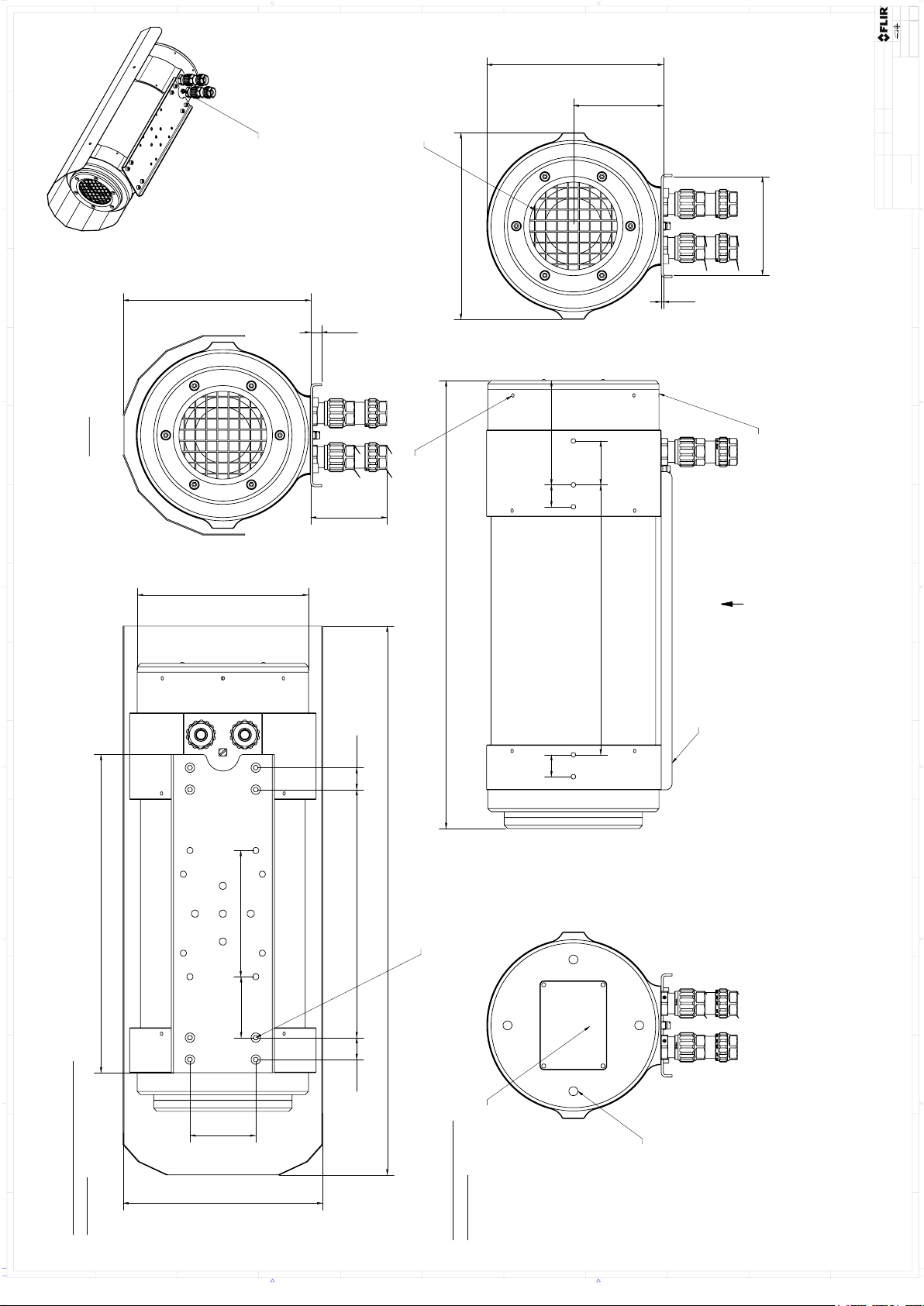
408,20
156,00
60,00
20,00 226,00
170,00
40,00
20,0020,00 95,00
246,00
82,00
2,00
55,50
20,00
115,00
161,00
90,00
290,00
500,00
182,00
171,00
10,00
70mm depending on
EX cable gland
A
A ( 1 : 2 )
Type
label
Mounting
rail
Protective
grid
8x Mounting holes with
M5x8 deep
for Mounting rail or
mounting plate
Overview with Sunshield
installed
Drawing without
Sunshield
Earthing
connection
Hole for
installation
wrench
4x Clamping
screws
Index
screw
All dimensions in
mm
Denna handling får ej delges annan, kopieras i
sin helhet eller delar utan vårt medgivande .
Överträdelse härav beivras med stöd av gällande lag.
FLIR SYSTEMS AB
This document must not be communicated or
copied completely or in part, without our permission.
Any infringement will lead to legal proceedings.
FLIR SYSTEMS AB
Där ej annat anges/Unless otherwise stated
Kanter brutna
Edges broken
Hålkälsradier
Fillet radii
Ytjämnhet/Roughness
Blad/Sheet
Rev
Ritn nr/Drawing No
Art.No.
Skala/Scale
Size
Datum/Date
Kontr/Check
Konstr/Drawn
Material
Ytbehandling/Surface treatment
Gen tol
Benämning/Denomination
A0
Utdrag ur/Excerpt from
ISO 2768-m
±0,1
±0,2
±0,3
±0,5
±0,8
(400)-1000
(120)-400
(30)-120
(6)-30
0,5-6
ISO 2768-mK
1(1)
2:1
H. ÖSTLING
A
T128183
A3xxEx
Basic Dimensions
JAMA
2014-04-14
2014-05-15
H. ÖSTLING
Ändrad av/Modified by
Ändrad/Modified
Ra µm
1 2 3 4 5 6 7 8 9 10 11 12 13 14 15 16
101 11732 1284 1395 6
A
B
C
D
E
F
G
H
I
J
K
B
J
F
G
C
H
D
A
I
E
K
-
Page 26

10
EC Type Examination Certificate
[See next page]
#T559891; r. AE/57789/57789; en-US
20
Page 27
Page 28
Page 29

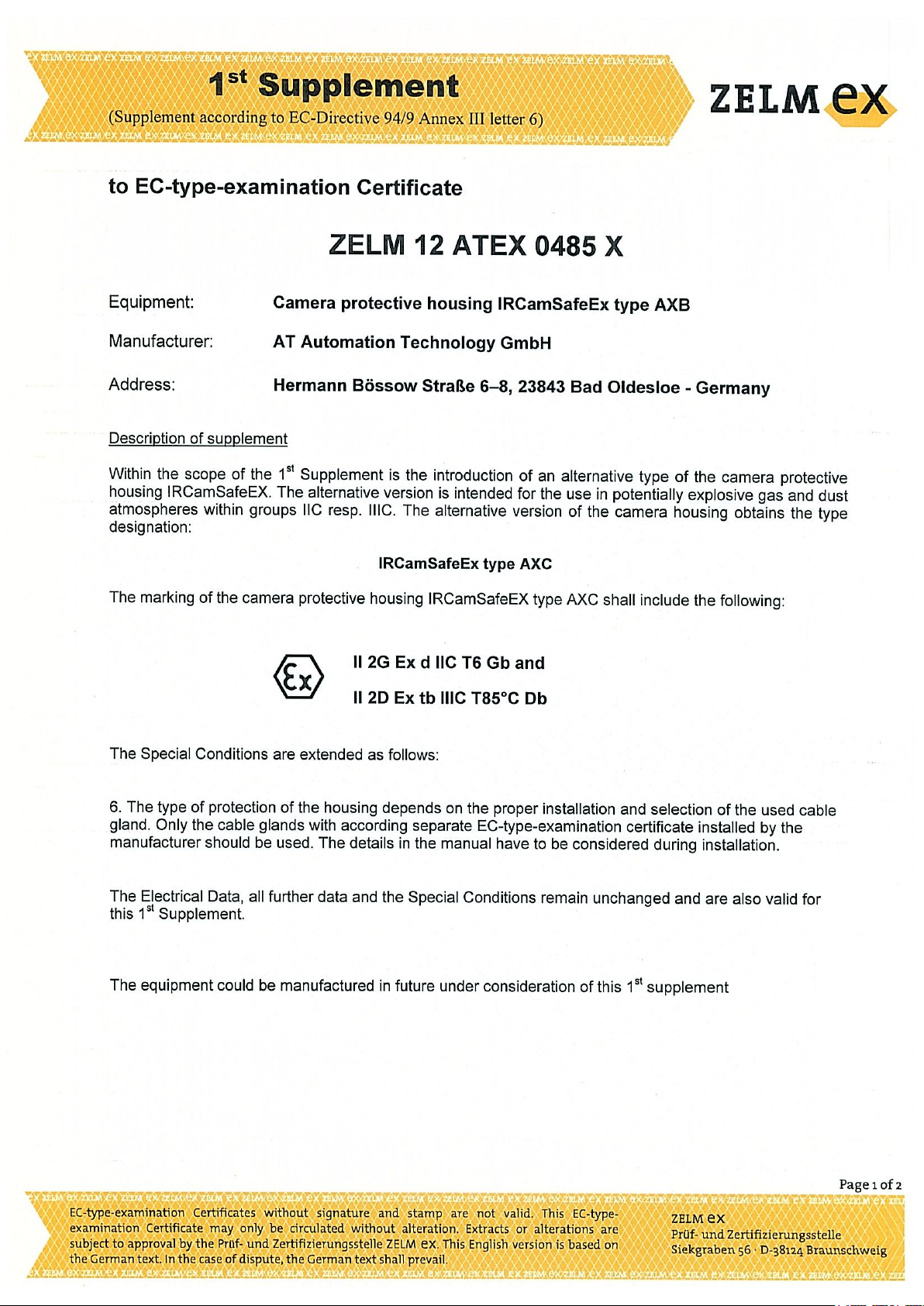
11
EC Type Examination Certificate, 1st supplement
[See next page]
#T559891; r. AE/57789/57789; en-US
23
Page 30
Page 31

Page 32

12
EC Type Examination Certificate, 2nd supplement
[See next page]
#T559891; r. AE/57789/57789; en-US
26
Page 33

Page 34

13
EC Type Examination Certificate, 3rd supplement
[See next page]
#T559891; r. AE/57789/57789; en-US
28
Page 35

Page 36

Page 37

14
EC Declaration of conformity (enclosure)
[See next page]
#T559891; r. AE/57789/57789; en-US
31
Page 38

EG-Konformitätserklärung
EC-Declaration of Conformity
Déclaration de Conformité CE
AT – Automation Technology GmbH • Hermann-Bössow-Strasse 6 – 8 • D-23843 Bad Oldesloe, Germany
erklärt in alleiniger Verantwortung,
declares in its sole responsibility,
déclare sous sa seule responsabilité
dass das Produkt
that the product
que le produit
IRCamSafeEX-AXB
IRCamSafeEX-AXC
Kennzeichnung, marking, marquage (-AXB):
Kennzeichnung, marking, marquage (-AXC):
II 2G Ex d IIB T6 Gb
II 2G Ex d IIC T6 Gb
II 2D Ex tb IIIC T85° Db
mit der EG-Baumusterprüfbescheinigung:
under EC-Type Examination Certificate:
avec Attestation d’examen CE de type:
ZELM 12 ATEX 0485 X
(ZELM Ex e.K.
Siekgraben 56, 38124 Braunschweig)
Kenn-Nr. der benannten Stelle:
Notified Body number:
No de l’organisme de certification:
0820
auf das sich diese Erklärung bezieht, mit den folgenden Normen oder normativen Dokumenten übereinstimmt
which is the subject of this declaration, is in conformity with the following standards or normative documents
auquel cette déclaration se rapporte, est conforme aux normes ou aux documents normatifs suivants
Bestimmungen der Richtlinie
Terms of the directive
Prescription de la directive
Nummer sowie Ausgabedatum der Norm
Number and date of issue of the standard
Numéro ainsi que date d’émission de la norme
94/9/EG: ATEX-Richtlinie
94/9/EC: ATEX Directive
94/9/CE: Directive ATEX
EN 60079-0: 2009
EN 60079-1: 2007
EN 60079-14: 2009
EN 60079-17: 2008
EN 60079-28: 2007
EN 60079-31: 2009
2006/95/EG: Niederspannungsrichtlinie
2006/95/EC: Low Voltage Directive
2006/95/CE: Directive Basse Tension
2004/108/EG: EMV-Richtlinie
2004/108/EC: EMC Directive
2004/108/CE: Directive CEM
Bad Oldesloe, 16. Mai. 2012
Ort und Datum
Place and Date
Lieu et date
Dr. Andrè Kasper
Leiter Qualitätssicherung
Director Quality Management Dept.
Directeur Dept. Assurance de Qualité
Page 39

15
Certiticate of conformity (camera)
[See next page]
#T559891; r. AE/57789/57789; en-US
33
Page 40

Page 41

16
Thermographic measurement techniques
16.1 Introduction
An infrared camera measures and images the emitted infrared radiation from an object.
The fact that radiation is a function of object surface temperature makes it possible for
the camera to calculate and display this temperature.
However, the radiation measured by the camera does not only depend on the temperature of the object but is also a function of the emissivity. Radiation also originates from
the surroundings and is reflected in the object. The radiation from the object and the reflected radiation will also be influenced by the absorption of the atmosphere.
To measure temperature accurately, it is therefore necessary to compensate for the effects of a number of different radiation sources. This is done on-line automatically by the
camera. The following object parameters must, however, be supplied for the camera:
• The emissivity of the object
• The reflected apparent temperature
• The distance between the object and the camera
• The relative humidity
• Temperature of the atmosphere
16.2 Emissivity
The most important object parameter to set correctly is the emissivity which, in short, is a
measure of how much radiation is emitted from the object, compared to that from a perfect blackbody of the same temperature.
Normally, object materials and surface treatments exhibit emissivity ranging from approximately 0.1 to 0.95. A highly polished (mirror) surface falls below 0.1, while an oxidized
or painted surface has a higher emissivity. Oil-based paint, regardless of color in the visible spectrum, has an emissivity over 0.9 in the infrared. Human skin exhibits an emissivity 0.97 to 0.98.
Non-oxidized metals represent an extreme case of perfect opacity and high reflexivity,
which does not vary greatly with wavelength. Consequently, the emissivity of metals is
low – only increasing with temperature. For non-metals, emissivity tends to be high, and
decreases with temperature.
16.2.1 Finding the emissivity of a sample
16.2.1.1 Step 1: Determining reflected apparent temperature
Use one of the following two methods to determine reflected apparent temperature:
#T559891; r. AE/57789/57789; en-US
35
Page 42

Thermographic measurement techniques16
16.2.1.1.1 Method 1: Direct method
Follow this procedure:
1. Look for possible reflection sources, considering that the incident angle = reflection
angle (a = b).
Figure 16.1 1 = Reflection source
2. If the reflection source is a spot source, modify the source by obstructing it using a
piece if cardboard.
Figure 16.2 1 = Reflection source
#T559891; r. AE/57789/57789; en-US
36
Page 43

Thermographic measurement techniques16
3. Measure the radiation intensity (= apparent temperature) from the reflection source
using the following settings:
• Emissivity: 1.0
• D
: 0
obj
You can measure the radiation intensity using one of the following two methods:
Figure 16.3 1 = Reflection source Figure 16.4 1 = Reflection source
You can not use a thermocouple to measure reflected apparent temperature, because a
thermocouple measures temperature, but apparent temperatrure is radiation intensity.
16.2.1.1.2 Method 2: Reflector method
Follow this procedure:
1. Crumble up a large piece of aluminum foil.
2. Uncrumble the aluminum foil and attach it to a piece of cardboard of the same size.
3. Put the piece of cardboard in front of the object you want to measure. Make sure that
the side with aluminum foil points to the camera.
4. Set the emissivity to 1.0.
#T559891; r. AE/57789/57789; en-US
37
Page 44

Thermographic measurement techniques16
5. Measure the apparent temperature of the aluminum foil and write it down. The foil is
considered a perfect reflector, so its apparent temperature equals the reflected apparent temperature from the surroundings.
Figure 16.5 Measuring the apparent temperature of the aluminum foil.
16.2.1.2 Step 2: Determining the emissivity
Follow this procedure:
1. Select a place to put the sample.
2. Determine and set reflected apparent temperature according to the previous
procedure.
3. Put a piece of electrical tape with known high emissivity on the sample.
4. Heat the sample at least 20 K above room temperature. Heating must be reasonably
even.
5. Focus and auto-adjust the camera, and freeze the image.
6. Adjust Level and Span for best image brightness and contrast.
7. Set emissivity to that of the tape (usually 0.97).
8. Measure the temperature of the tape using one of the following measurement
functions:
• Isotherm (helps you to determine both the temperature and how evenly you have
heated the sample)
• Spot (simpler)
• Box Avg (good for surfaces with varying emissivity).
9. Write down the temperature.
10. Move your measurement function to the sample surface.
11. Change the emissivity setting until you read the same temperature as your previous
measurement.
12. Write down the emissivity.
Note
• Avoid forced convection
• Look for a thermally stable surrounding that will not generate spot reflections
• Use high quality tape that you know is not transparent, and has a high emissivity you
are certain of
• This method assumes that the temperature of your tape and the sample surface are
the same. If they are not, your emissivity measurement will be wrong.
#T559891; r. AE/57789/57789; en-US
38
Page 45

Thermographic measurement techniques16
16.3 Reflected apparent temperature
This parameter is used to compensate for the radiation reflected in the object. If the
emissivity is low and the object temperature relatively far from that of the reflected it will
be important to set and compensate for the reflected apparent temperature correctly.
16.4 Distance
The distance is the distance between the object and the front lens of the camera. This
parameter is used to compensate for the following two facts:
• That radiation from the target is absorbed by the atmosphere between the object and
the camera.
• That radiation from the atmosphere itself is detected by the camera.
16.5 Relative humidity
The camera can also compensate for the fact that the transmittance is also dependent
on the relative humidity of the atmosphere. To do this set the relative humidity to the correct value. For short distances and normal humidity the relative humidity can normally be
left at a default value of 50%.
16.6 Other parameters
In addition, some cameras and analysis programs from FLIR Systems allow you to compensate for the following parameters:
• Atmospheric temperature – i.e. the temperature of the atmosphere between the cam-
era and the target
• External optics temperature – i.e. the temperature of any external lenses or windows
used in front of the camera
• External optics transmittance – i.e. the transmission of any external lenses or windows
used in front of the camera
#T559891; r. AE/57789/57789; en-US
39
Page 46

17
About FLIR Systems
FLIR Systems was established in 1978 to pioneer the development of high-performance
infrared imaging systems, and is the world leader in the design, manufacture, and marketing of thermal imaging systems for a wide variety of commercial, industrial, and government applications. Today, FLIR Systems embraces five major companies with
outstanding achievements in infrared technology since 1958—the Swedish AGEMA Infrared Systems (formerly AGA Infrared Systems), the three United States companies Indigo Systems, FSI, and Inframetrics, and the French company Cedip.
Since 2007, FLIR Systems has acquired several companies with world-leading
expertise:
• NEOS (2019)
• Endeavor Robotics (2019)
• Aeryon Labs (2019)
• Seapilot (2018)
• Acyclica (2018)
• Prox Dynamics (2016)
• Point Grey Research (2016)
• DVTEL (2015)
• DigitalOptics micro-optics business (2013)
• MARSS (2013)
• Traficon (2012)
• Aerius Photonics (2011)
• TackTick Marine Digital Instruments (2011)
• ICx Technologies (2010)
• Raymarine (2010)
• Directed Perception (2009)
• OmniTech Partners (2009)
• Salvador Imaging (2009)
• Ifara Tecnologías (2008)
• Extech Instruments (2007)
Figure 17.1 Patent documents from the early 1960s
FLIR Systems has three manufacturing plants in the United States (Portland, OR, Boston,
MA, Santa Barbara, CA) and one in Sweden (Stockholm). Since 2007 there is also a
manufacturing plant in Tallinn, Estonia. Direct sales offices in Belgium, Brazil, China,
#T559891; r. AE/57789/57789; en-US
40
Page 47

17
About FLIR Systems
France, Germany, Great Britain, Hong Kong, Italy, Japan, Korea, Sweden, and the USA
—together with a worldwide network of agents and distributors—support our international customer base.
FLIR Systems is at the forefront of innovation in the infrared camera industry. We anticipate market demand by constantly improving our existing cameras and developing new
ones. The company has set milestones in product design and development such as the
introduction of the first battery-operated portable camera for industrial inspections, and
the first uncooled infrared camera, to mention just two innovations.
1969: Thermovision Model 661. The camera
weighed approximately 25 kg (55 lb.), the oscilloscope 20 kg (44 lb.), and the tripod 15 kg (33 lb.).
The operator also needed a 220 VAC generator
set, and a 10 L (2.6 US gallon) jar with liquid nitrogen. To the left of the oscilloscope the Polaroid attachment (6 kg (13 lb.)) can be seen.
2015: FLIR One, an accessory to iPhone and Android mobile phones. Weight: 36 g (1.3 oz.).
FLIR Systems manufactures all vital mechanical and electronic components of the camera systems itself. From detector design and manufacturing, to lenses and system electronics, to final testing and calibration, all production steps are carried out and
supervised by our own engineers. The in-depth expertise of these infrared specialists ensures the accuracy and reliability of all vital components that are assembled into your infrared camera.
17.1 More than just an infrared camera
At FLIR Systems we recognize that our job is to go beyond just producing the best infrared camera systems. We are committed to enabling all users of our infrared camera systems to work more productively by providing them with the most powerful camera–
software combination. Especially tailored software for predictive maintenance, R & D,
and process monitoring is developed in-house. Most software is available in a wide variety of languages.
We support all our infrared cameras with a wide variety of accessories to adapt your
equipment to the most demanding infrared applications.
17.2 Sharing our knowledge
Although our cameras are designed to be very user-friendly, there is a lot more to thermography than just knowing how to handle a camera. Therefore, FLIR Systems has
founded the Infrared Training Center (ITC), a separate business unit, that provides certified training courses. Attending one of the ITC courses will give you a truly hands-on
learning experience.
#T559891; r. AE/57789/57789; en-US
41
Page 48

17
About FLIR Systems
The staff of the ITC are also there to provide you with any application support you may
need in putting infrared theory into practice.
17.3 Supporting our customers
FLIR Systems operates a worldwide service network to keep your camera running at all
times. If you discover a problem with your camera, local service centers have all the
equipment and expertise to solve it within the shortest possible time. Therefore, there is
no need to send your camera to the other side of the world or to talk to someone who
does not speak your language.
#T559891; r. AE/57789/57789; en-US
42
Page 49

This section contains the original manual from the manufacturer of the enclosure.
Page 50

Betriebsanleitung
IRCamSafeEX-AXC Ex-d Gehäuse für
Infrarotkameras
AT – Automation Technology GmbH
Datum: 01.04.2017
Revision: 1.4
© AT – Automation Technology GmbH 2016
Page 51

Betriebsanleitung IRCamSafeEX-AXC
Ex-d Gehäuse für Infrarotkameras 1 AT-Automation Technology GmbH
1 Inhaltsverzeichnis
2 Allgemeine Angaben........................................................................................................................ 2
2.1 Hersteller ................................................................................................................................. 2
2.2 Einleitung ................................................................................................................................. 2
2.3 Kennzeichnung ........................................................................................................................ 3
3 Allgemeine Sicherheitshinweise ...................................................................................................... 4
4 Verwendung und Vorgesehener Einsatzbereich ............................................................................. 5
4.1 Zulässige Einbauten ................................................................................................................. 5
4.2 Zulässige Kabeleinführungen und Steckverbinder .................................................................. 6
4.3 Ausführung mit vorkonfektionierten Anschlusskabeln ........................................................... 6
5 Normenkonformität ........................................................................................................................ 7
6 Technische Daten ............................................................................................................................ 8
7 Transport, Lagerung und Entsorgung ........................................................................................... 10
8 Montage und Demontage ............................................................................................................. 10
9 Installation ..................................................................................................................................... 11
9.1 Installation der Anschlussleitungen ...................................................................................... 12
9.1.1 Hinteren Gehäusedeckel abschrauben ......................................................................... 12
9.1.2 Auflegen der Anschlussleitungen .................................................................................. 12
9.1.3 Hinteren Gehäusedeckel schließen ............................................................................... 13
9.1.4 Erdungsanschluss auflegen ........................................................................................... 13
10 Inbetriebnahme ......................................................................................................................... 14
11 Wartung ..................................................................................................................................... 15
11.1 Regelmäßige Wartungsarbeiten ............................................................................................ 15
11.2 Reinigung ............................................................................................................................... 16
12 Zubehör und Ersatzteile ............................................................................................................ 16
13 EG-Baumusterprüfbescheinigung ............................................................................................. 17
14 EU-Konformitätserklärung......................................................................................................... 24
Page 52

Betriebsanleitung IRCamSafeEX-AXC
Ex-d Gehäuse für Infrarotkameras 2 AT-Automation Technology GmbH
2 Allgemeine Angaben
2.1 Hersteller
AT-Automation Technology GmbH
Hermann-Bössow-Str. 6-8
23843 Bad Oldesloe
Germany
Telefon: +49 4531 88011-0
Telefax: +49 34531 88011-20
Internet: www.AutomationTechnology.de
2.2 Einleitung
Bei den Kameragehäusen der Serie IRCamSafeEX-AXB/C handelt es sich um Schutzgehäuse für
Infrarotkameras. Die Gehäuse sind für den Einsatz von Infrarotkameras der Serie FLIR
A3XX/SC3XX und A615/SC6XX, sowie Flir G300A und AT IRS und Xenics Serval in
explosionsgefährdeten Bereichen konzipiert. Die Variante–AXC ist zudem für den Einsatz in
staubexplosionsgefährlicher Atmosphäre zugelassen.
Die Schutzgehäuse erfüllen die aktuellen EX-Schutz Normen und sind als komplette Einheit mit
allen Einbauten zertifiziert. Eine zusätzliche Zertifizierung nach Einbau der vorgesehenen
Kameras ist somit nicht mehr notwendig.
Page 53

Betriebsanleitung IRCamSafeEX-AXC
Ex-d Gehäuse für Infrarotkameras 3 AT-Automation Technology GmbH
2.3 Kennzeichnung
Gehäusevariante 24V DC:
AT – Automation Technology GmbH
Hermann-Bössow-Straße 6 – 8 • 23843 Bad Oldesloe • Germany
Phone: +49 4531 88011-0 • www.AutomationTechnology.de
Model:
IRCamSafeEX-AXC
Serial No.:
71000260
Year: 2016
Power:
24VDC, 60W
max.
T
amb
-40°C - +40°C / 60°C
Certificate:
ZELM 12 ATEX 0485 X
2572
IP67
WARNUNG / WARNING / ADVERTENCIA / ATTENTION !
NICHT UNTER SPANNUNG ÖFFNEN / DE-ENERGIZE BEFORE OPENING
DESENERGIZAR ANTES DE ABRIR / NE PAS OUVIRIR SOUS TENSION
NACH DEM ABSCHALTEN 10 MINUTEN WARTEN VOR DEM ÖFFNEN.
Gehäusevariante 230V AC:
AT – Automation Technology GmbH
Hermann-Bössow-Straße 6 – 8 • 23843 Bad Oldesloe • Germany
Phone: +49 4531 88011-0 • www.AutomationTechnology.de
Model:
IRCamSafeEX-AXC
Serial No.:
71000260
Year: 2016
Power:
230VAC, 60W
max.
T
amb
-40°C - +40°C / 60°C
Certificate:
ZELM 12 ATEX 0485 X
2572
IP67
WARNUNG / WARNING / ADVERTENCIA / ATTENTION !
NICHT UNTER SPANNUNG ÖFFNEN / DE-ENERGIZE BEFORE OPENING
DESENERGIZAR ANTES DE ABRIR / NE PAS OUVIRIR SOUS TENSION
NACH DEM ABSCHALTEN 10 MINUTEN WARTEN VOR DEM ÖFFNEN.
II 2G Ex db IIC T6 / T5
II 2D Ex tb IIIC T85° / T100°
II 2G Ex db IIC T6 / T5
II 2D Ex tb IIIC T85° / T100°
Page 54

Betriebsanleitung IRCamSafeEX-AXC
Ex-d Gehäuse für Infrarotkameras 4 AT-Automation Technology GmbH
3 Allgemeine Sicherheitshinweise
Die Betriebsanleitung enthält grundlegende Sicherheitshinweise, die bei Aufstellung, Betrieb
und Wartung zu beachten sind. Nichtbeachtung hat eine Gefährdung für Personen, Anlage und
Umwelt zur Folge.
Gefahr durch unbefugte Arbeiten am Gerät!
Montage, Installation, Inbetriebnahme, Betrieb und Wartung dürfen ausschließlich von
dazu befugtem und entsprechend geschultem Personal durchgeführt werden.
Vor Montage/Inbetriebnahme:
Betriebsanleitung lesen.
Montage- und Betriebspersonal ausreichend schulen.
Sicherstellen, dass der Inhalt der Betriebsanleitung vom zuständigen Personal voll
verstanden wird.
Es gelten die nationalen Montage- und Errichtungsvorschriften (z.B. IEC/EN 60079-14).
Bei Unklarheiten:
Mit dem Hersteller Kontakt aufnehmen.
Bei Betrieb der Geräte:
Betriebsanleitung am Einsatzort verfügbar halten.
Sicherheitshinweise beachten.
Nationale Sicherheits- und Unfallverhütungsvorschriften beachten.
Gerät nur entsprechend der Leistungsdaten betreiben.
Wartungsarbeiten bzw. Reparaturen, die nicht in der Betriebsanleitung beschrieben
sind, dürfen nicht ohne vorherige Abstimmung mit dem Hersteller durchgeführt werden.
Beschädigungen können den Explosionsschutz aufheben.
Umbauten und Veränderungen am Gerät, die den Explosionsschutz beeinträchtigen, sind
nicht gestattet.
Gerät nur in unbeschädigtem, trockenem und sauberem Zustand einbauen und
betreiben.
Page 55

Betriebsanleitung IRCamSafeEX-AXC
Ex-d Gehäuse für Infrarotkameras 5 AT-Automation Technology GmbH
4 Verwendung und Vorgesehener Einsatzbereich
Die Schutzgehäuse sind für den Einsatz von Infrarotkameras in explosionsgefährdeten
Bereichen der Zone 1 und 2, sowie 21 und 22 zugelassen.
Gerät nur bestimmungsgemäß einsetzen!
Sonst erlischt Herstellerhaftung und Gewährleistung.
Gerät ausschließlich entsprechend den in dieser Betriebsanleitung festgelegten Betriebs-
bedingungen verwenden.
Das Gerät darf in explosionsgefährdeten Bereichen nur gemäß dieser Betriebsanleitung betrieben
werden.
4.1 Zulässige Einbauten
Folgende Kamera und Optikkombinationen können eingesetzt werden.
Kamera
Optik
Variante
- AXC
Flir A3XX,
SC3XX,
A3XXsc
ohne Zusatzoptik
X
45° Zusatzoptik, f‘ = 10mm
X
15° Zusatzoptik, f‘ = 30mm
X
6° Zusatzoptik, f‘ = 76mm
X
90° Zusatzoptik, f‘ = 4mm
X
Flir A615,
SC6XX,
A6XXsc
15° Optik, f‘ = 41,3mm
X
25° Optik, f‘ = 24,6mm
X
45° Optik, f‘ = 13,1mm
X
AT IRS-X-GigE
WFOV Optiken
X
IRS-X-GigE
Xenics Serval-X-GigE
Optik, f‘ = 11mm
X
Optik, f‘ = 25mm
X
Optik, f‘ =35mm
X
Optik, f‘ = 60mm
X
Optik, f‘ = 100mm
X
Optik, f‘=35-105mm
X
Flir AX5
WFOV Optiken
X
Flir G300A
f‘ = 23mm, F=1,5
f‘=38mm, F=1,5
X
Installationsarbeiten nur durch Fachpersonal!
Die Montage der Einbauten erfolgt durch den Hersteller oder durch vom Hersteller autorisiertes
Personal.
Page 56

Betriebsanleitung IRCamSafeEX-AXC
Ex-d Gehäuse für Infrarotkameras 6 AT-Automation Technology GmbH
4.2 Zulässige Kabeleinführungen und Steckverbinder
Für den Anschluss der Stromversorgungsleitung und der Datenübertragungsleitung stehen zwei
druckfeste und zünddurchschlagsichere Kabeleinführungen zur Verfügung. Alternativ können
druckfeste und zünddurchschlagsichere Steckverbindersysteme eingesetzt werden. Die
Kabeleinführungen und Steckverbinderbuchsen sind vom Hersteller vormontiert. Optional wird
vom Hersteller das Gehäuse zusätzlich mit bereits angeschlossenen Anschlusskabeln geliefert.
Folgende EX-Kabeleinführungen sind für die Verwendung mit dem Schutzgehäuse geeignet.
Hersteller
Bezeichnung
Größe
Manteldurchmesser
A1 mm
Max. Anzahl
Einzeladern
Stahl
8163/2-20S/16-PXSS2K-M20
20s/16
3.1– 8.7
15
Stahl
8163/2-20S-PXSS2K-M20
20s
6.1 – 11.7
15
Stahl
8163/2-20-PXSS2K-M20
20
6.5 – 14.0
15
Stahl
8163/2-20S/16-PX2K-M20
20s/16
6.1 - 11.5
15
Stahl
8163/2-20S-PX2K-M20
20s
9.5 – 15.9
15
Stahl
8163/2-20-PX2K-M20
20
12.5 – 20.9
15
Hummel
EXIOS Barrier 1.606.2000.50
20-1
6 – 12
8
Hummel
EXIOS Barrier 1.606.2000.51
20-2
9 – 16
10
Hummel
EXIOS Barrier 1.606.2000.52
20-3
12.5 – 20.5
15
Folgende EX-Steckverbindersysteme sind für die Verwendung mit dem Schutzgehäuse geeignet.
Hersteller
Beschreibung
Bezeichnung
Stahl
Gerätestecker für Stromversorgungsanschluss
2 polig + PE
8591/16.-06-3.00
Stahl
Gerätestecker in Ethernet Ausführung 4 polig
8591/467-01-3022
Hawke
Einbaubuchse für Stromversorgungsanschluss, 4 polig
N-BR1-M-B-P-X-0-3-X-A
Hawke
Einbaubuchse für Ethernetanschluss, 8 polig
N-BR1-M-C-P-X-0-8-X-A
Im Zuge von Aktualisierungen kann sich die Kennzeichnung entsprechend den aktuellen
Normanforderungen ändern.
Installationsarbeiten nur durch Fachpersonal!
Die Montage der Kabeleinführungen und der gehäuseseitigen Steckverbinder erfolgt durch den
Hersteller oder durch vom Hersteller autorisiertes Personal.
4.3 Ausführung mit vorkonfektionierten Anschlusskabeln
Anschluss 1 (Datenverbindung) ist mit einem LWL-Anschlusskabel mit folgenden Eigenschaften
ausgestattet.
Vieradriges LWL Breakoutkabel für den Außeneinsatz, AT-V(ZN)Y(ZN)Y 4G50/125 OM2 oder
62.5/125 OM1 (z.B. Helukabel 803348 mit Manteldurchmesser 8,5mm)
4x LC Stecker auf der Gehäuseinnenseite vorkonfektioniert, Einzelader Innenlänge 450mm
Page 57

Betriebsanleitung IRCamSafeEX-AXC
Ex-d Gehäuse für Infrarotkameras 7 AT-Automation Technology GmbH
Zweite Anschlussseite ist nicht-konfektioniert und zum Spleißen geeignet
Typische Länge 5m
Anschluss 2 (Stromversorgung) ist mit einem 3 adrigen Kupfer-Kabel (z.B. Helukabel 37264) mit
folgenden Eigenschaften ausgestattet:
Manteldurchmesser: 9,8mm
Aderquerschnitt: 3 x 1,5mm
2
feindrähtig
Typische Länge 5m, optional mit Stecker Stahl 8570/12-306 konfektioniert
Kundenspezifische Längen und Konfektionierungen der freien Enden sind auf Anfrage möglich.
5 Normenkonformität
Die Schutzgehäuse entsprechen den folgenden Normen und Richtlinien:
Richtlinie 2014/34/EU
EN 60079-0:2012+A11:2013; „Explosionsfähige Atmosphäre - Teil 0: Geräte - Allgemeine
Anforderungen“
EN 60079-1:2014; „Explosionsfähige Atmosphäre - Teil 1: Geräteschutz durch druckfeste
Kapselung „d““
EN 600079-31:2014; „Explosionsfähige Atmosphäre - Teil 31: Geräte-Staubexplosionsschutz
durch Gehäuse "t"“
Für den Einsatz des Schutzgehäuses sind u.a. folgende Normen zu beachten:
EN 60079-14:2014; „Explosionsfähige Atmosphäre - Teil 14: Projektierung, Auswahl und
Errichtung elektrischer Anlagen“
EN 60079-17:2014; „Explosionsfähige Atmosphäre - Teil 17: Prüfung und Instandhaltung
elektrischer Anlagen“
EN 60079-28:2007; „Explosionsfähige Atmosphäre - Teil 28: Schutz von Einrichtungen und
Übertragungssystemen, die mit optischer Strahlung arbeiten“
Page 58

Betriebsanleitung IRCamSafeEX-AXC
Ex-d Gehäuse für Infrarotkameras 8 AT-Automation Technology GmbH
6 Technische Daten
Allgemeine technische Daten:
Normal-Betriebsumgebungstemperaturbereich T
a
: -40°C … +60°C
Schutzart: IP67
Gewicht: 6,7 kg (ohne Kamera und Optik)
Leervolumen: 5,06l
Außenmaße (ohne Sonnendach und Anschlüsse): D=170mm, L=408mm
Gehäusematerial: Aluminium
Oberfläche: pulverbeschichtet,
Material infrarotdurchlässiges Fenster: Germanium, beidseitig AR beschichtet, außen
zusätzlich hardcarbon beschichtet
Maximale Leistung der Zusatzheizung: 16W + 6W (Fensterheizung)
Optionale Zusatzheizung für kalte Gebiete: 18W
Betriebsspannung: 115VAC 60Hz / 230VAC 50Hz / 24V DC
Maximale elektrische Anschlussleistung: 60W
Integrierter Controller:
o 4 Port Switch mit 2x LWL-LC 100Base-FX oder 2x RJ45(10/100) Up-Links
o Unterstützt Ring-Topologie für reduzierten Verkabelungsaufwand
o 2 interne Temperatursensoren, Luftfeuchte und Drucksensor
o schaltbare Kameraversorgung und Zusatzheizung via Modbus-TCP/IP
o Web-Interface zur Konfiguration
EX-Schutz spezifische Angaben:
Für Einsatz in EX-Zone : 1, 2
Zündschutzart: druckfeste Kapselung „d“
Maximale Oberflächentemperaturen:
o Temperaturklasse T5: maximal +100°C (maximale Umgebungstemperatur +60°C)
o Temperaturklasse T6: maximal +85°C (maximale Umgebungstemperatur +40°C)
ATEX Kennzeichnung
o II 2G Ex db IIC T6 / T5
o II 2D Ex tb IIIC T85° / T100
Prüfbescheinigung: ZELM 12 ATEX 0485 X
Page 59

Betriebsanleitung IRCamSafeEX-AXC
Ex-d Gehäuse für Infrarotkameras 9 AT-Automation Technology GmbH
Abb. 1: Übersicht IRCamSafeEX-AXC (alle Maße in mm) – Änderungen vorbehalten
Page 60

Betriebsanleitung IRCamSafeEX-AXC
Ex-d Gehäuse für Infrarotkameras 10 AT-Automation Technology GmbH
7 Transport, Lagerung und Entsorgung
Transport:
Erschütterungsfrei in der Originalverpackung, nicht stürzen, vorsichtig handhaben.
Lagerung:
Trocken in der Originalverpackung lagern
Entsorgung:
Die umweltgerechte Entsorgung aller Bauteile gemäß den gesetzlichen Bestimmungen ist
sicherzustellen.
8 Montage und Demontage
Vor der Montage den Umgebungstemperaturbereich und die Schutzart gemäß Typenschild auf
Zulässigkeit im Montagebereich prüfen.
Die für die Montage vorgesehenen Befestigungsbohrungen sin der Zeichnung Abb. 1 zu entnehmen.
Für die Befestigung des Schutzgehäuses auf eine Montageplatte erfolgt können die 8x M5 Gewinde
des Schutzgehäuses verwendet werden. Alternativ kann eine Befestigungsschiene zur Montage auf
einer Wandhalterung verwendet werden. Bei der Montage auf festen Sitz der Schrauben achten,
maximal 3.5Nm Anzugsdrehmoment in den M5 – Befestigungsgewinden verwenden. Die Be-
festigungsschrauben sind gegen Selbstlockern mit Sicherungsscheiben zu sichern.
Bei freier Bewetterung wird empfohlen, das Schutzgehäuse mit Sonnenschutzdach
auszurüsten.
Page 61

Betriebsanleitung IRCamSafeEX-AXC
Ex-d Gehäuse für Infrarotkameras 11 AT-Automation Technology GmbH
9 Installation
Installationsarbeiten nur durch Fachpersonal!
Installationsarbeiten dürfen nur von dazu befugtem und entsprechend geschultem Personal
durchgeführt werden. Geltende nationale Bestimmungen im Einsatzland, z.B. EN 60079-14
beachten. Die Montage der Kabeleinführungen oder gehäuseseitigen Steckverbinder und die
Installation der Anschlussleitungen erfolgt durch den Hersteller oder durch vom Hersteller
autorisiertes Personal.
Gefahr durch spannungsführende Teile!
Es ist sicherzustellen, dass alle Zuleitungen spannungsfrei geschaltet sind und gegen unbefugtes
Schalten gesichert sind.
Gefahr durch unzulässige Kabeleinführungen!
Bei Verwendung unzulässiger Kabeleinführungen ist der Explosionsschutz nicht mehr ge-
währleistet. Nur Kabeleinführungen verwenden, die für die geforderte Zündschutzart zugelassen
sind und für das Gehäuse vom Hersteller benannt sind, s. Abschnitt „Zulässige Kabeleinführungen
und Steckverbinder“.
Gefahr durch fehlerhafte Zugentlastung!
Bei Verwendung von Kabeleinführungen ist bei fehlerhafter Zugentlastung der Explosionsschutz
nicht mehr gewährleistet. Kabel und Leitungen fest verlegen. Betriebsanleitung zur Kabel-
durchführung beachten.
Gefahr durch beschädigte Gewinde!
Bei beschädigten Gewinden ist der zünddurchschlagssichere Spalt nicht mehr gewährleistet.
Gehäusedeckel vorsichtig ablegen bzw. vorsichtig auf das Gehäuse aufsetzen. Gehäusedeckel oder
Gehäuse mit beschädigtem Gewinde sofort austauschen!
Gefahr durch fehlerhafte Abdichtung!
Der Explosionsschutz ist in hohem Maße von der Einhaltung der IP-Schutzart abhängig. Bei allen
Arbeiten auf korrekten Sitz und einwandfreien Zustand aller Dichtungen achten.
Page 62

Betriebsanleitung IRCamSafeEX-AXC
Ex-d Gehäuse für Infrarotkameras 12 AT-Automation Technology GmbH
9.1 Installation der Anschlussleitungen
Leitungen
Die Qualität der verwendeten Zuleitung ist so zu wählen, dass sie den thermischen und
mechanischen Anforderungen im Einsatzbereich genügt. Die Kabel müssen den entsprechenden
Richtlinien für direkte Einführung in druckfeste Kapselung nach EN 60079-14 genügen. Die
Kabeleinführung ist mit Vergussmasse zur Abdichtung der Einzeladern auszuführen.
Abb. 2: Darstellung der Anschlüsse am Controllerboard
9.1.1 Hinteren Gehäusedeckel abschrauben
1. 1x Gehäuseindexschraube lösen
2. 4x Gehäuseklemmschraube lösen
3. Montageschlüssel für Deckel hinten aufsetzen und Gehäusedeckel abschrauben
4. Gehäusedeckel vorsichtig ablegen
9.1.2 Auflegen der Anschlussleitungen
Führen Sie die Anschlussleitungen mit der kompletten äußeren Isolation durch die
Kabeleinführungen in den Anschlussraum.
Stellen Sie dabei sicher, dass der Kabeldurchmesser mit dem Klemmquerschnitt auf der
Kabeleinführung übereinstimmt und die Abdichtung mit der Vergussmasse gemäß
Bedienungsanleitung der Kabeleinführung ausgeführt ist.
Ziehen Sie die Sechskantmuttern der Kabeleinführung so fest an, dass die Dichtheit des
Anschlussraumes sowie der Zugentlastungsschutz der Anschlussstellen gesichert sind.
Die Anzugsdrehmomente entnehmen Sie den Betriebsanleitungen der Komponenten.
Verlegen Sie die Anschlussleitungen im Anschlussraum so, dass:
o Die für den jeweiligen Leiterquerschnitt zulässigen minimalen Biegeradien nicht
unterschritten werden.
o Mechanische Beschädigungen der Leiterisolation ausgeschlossen sind.
LWL-LC Anschluss
Anschluss Versorgungsleitung
Page 63

Betriebsanleitung IRCamSafeEX-AXC
Ex-d Gehäuse für Infrarotkameras 13 AT-Automation Technology GmbH
Nicht korrekt durchgeführte Installation!
Bitte beachten Sie die Gewindegrößen für die Leitungseinführungen in der Dokumentation
des Betriebsmittels.
Die Anschlussleistung muss den geltenden Vorschriften entsprechen und über den
erforderlichen Querschnitt verfügen. Der Durchmesser muss mit den Angaben auf der
Kabeldurchführung übereinstimmen.
Durch geeignete Auswahl der verwendeten Leitungen sowie durch die Art der Verlegung
muss sichergestellt sein, dass maximal zulässige Leitertemperaturen nicht überschritten
werden.
Die zulässige Umgebungstemperatur an den eingebauten Komponenten darf nicht
überschritten werden.
Es muss sichergestellt werden, dass beim Abisolieren die Leiterisolation bis an die
Klemmen heranreicht.
Der Leiter darf beim Abisolieren nicht beschädigt werden.
Die Schaltgerätekombination darf nur in trockener und sauberer Umgebung installiert
werden.
9.1.3 Hinteren Gehäusedeckel schließen
1. Korrekten Sitz und einwandfreien Zustand des O-Rings prüfen
2. Gewinde des hinteren Deckels auf einwandfreien Zustand und Sauberkeit prüfen. Bei
Beschädigung des Gewindes muss der Deckel ausgetauscht werden!
3. Prüfen das auf dem Gewinde Montagepaste (z.B. Teflonpaste) aufgebracht ist.
4. Neues Trockenmittel einsetzen
5. Gehäusedeckel vorsichtig aufsetzen und mit Hand zuschrauben
6. Montageschlüssel für Deckel hinten aufsetzen und Gehäusedeckel zuschrauben, bis
Indexposition erreicht ist
7. 1x Gehäuseindexschraube Gewindestift einschrauben und festziehen
8. 4x Gehäuseklemmschraube einschrauben und festziehen
9.1.4 Erdungsanschluss auflegen
Der Erdungsanschluss ist für feindrähtige Kabel bis 1,5mm2 und für eindrähtige Kabel bis 2,5mm2
geeignet. Das abisolierte Ende des Erdungskabels in den Erdungsanschluss einlegen und die M4-
Schraube des Erdungsanschlusses mit einem maximalen Anzugsdrehmoment von 1,2Nm festziehen.
Für größere Erdungsleiter ist der Anschluß über einen Ringkabelschuh möglich. Diese auf das Ende
des Erdungskabels nach Vorgaben des Herstellers aufpressen und am Erdungsanschluß mittels
Schraube befestigen. Anzugsmoment 1,2Nm.
Page 64

Betriebsanleitung IRCamSafeEX-AXC
Ex-d Gehäuse für Infrarotkameras 14 AT-Automation Technology GmbH
10 Inbetriebnahme
Vor der Inbetriebnahme
Sicherstellen, dass das Gerät nicht beschädigt ist.
Sicherstellen, dass das Gerät vorschriftsmäßig installiert ist.
Sicherstellen, dass das Fenster-Schutzgitter ordnungsgemäß montiert ist.
Kabeleinführungen auf Schäden untersuchen und auf festen Sitz prüfen.
Schrauben und Muttern auf festen Sitz prüfen.
Verlegung der Stromversorgungs- und Datenkabel prüfen. Kabelmantel auf Beschädigungen
untersuchen.
Anzugsdrehmomente kontrollieren.
Sicherstellen, dass ggf. nicht benutzte Kabel- und Leitungseinführungen mit gemäß Richtlinie
94/9/EG bescheinigten Stopfen abgedichtet sind.
Schritte während der Inbetriebnahme
1. Netzspannung zuschalten
2. Konfigurieren der Ethernet-Verbindung zum Schutzgehäusekontroller mit dem Tool „EDS
Configurator“
3. Starten der Website des Schutzgehäusekontrollers und ggf. Konfigurieren der Netzwerk-
Switch Einstellungen.
4. Prüfen und Konfigurieren der Ethernet-Verbindung zur Infrarotkamera mit dem Tool „FLIR IP
Config“
5. Starten der Monitorsoftware
6. Prüfen des Kamerabildes
7. Prüfen der Sensorwerte (Temperatur, Luftfeuchte, Druck) des Schutzgehäusekontrollers
Page 65

Betriebsanleitung IRCamSafeEX-AXC
Ex-d Gehäuse für Infrarotkameras 15 AT-Automation Technology GmbH
11 Wartung
Der Betreiber einer elektrischen Anlage in explosionsgefährdeter Umgebung hat diese in
ordnungsgemäßem Zustand zu halten, ordnungsgemäß zu betreiben, zu überwachen und
Instandhaltungs- sowie Instandsetzungsarbeiten durchzuführen! Wartungsarbeiten und Arbeiten zur
Störungsbeseitigung dürfen nur von Fachpersonal durchgeführt werden. Im Rahmen der Wartung
sind vor allem die Teile, von denen die Zündschutzart und die Funktionsfähigkeit abhängen, auf Ihren
ordnungsgemäßen Zustand zu prüfen. Vor der Wartung und/oder Störungsbeseitigung sind die
angegebenen Sicherheitsvorschriften zu beachten.
Gefahr durch spannungsführende Teile!
Vor Beginn der Wartungsarbeiten Gerät spannungsfrei schalten. Gerät gegen unbefugtes Schalten
sichern.
Gefahr bei Öffnen des Gehäuses oder der Kabelverschraubungen!
Vor Öffnen des Gehäuses oder der Kabelverschraubungen sind das Gerät und alle eventuell
angeschlossenen LWL-Einheiten spannungsfrei zu schalten und gegen unbefugtes Wieder-
einschalten zu sichern.
Installationsarbeiten nur durch Fachpersonal!
Installationsarbeiten dürfen nur von dazu befugtem und entsprechend geschultem Personal
durchgeführt werden. Geltende nationale Bestimmungen im Einsatzland, z.B. EN 60079-17 sind zu
beachten.
11.1 Regelmäßige Wartungsarbeiten
Art und Umfang der Prüfungen sind den entsprechenden nationalen Vorschriften (z.B. IEC/EN 60079-
17) zu entnehmen. Die Fristen sind so zu bemessen, dass entstehende Mängel in der Anlage, mit
denen zu rechnen ist, rechtzeitig festgestellt werden.
Im Rahmen der Wartung:
Das Gerät auf sichtbare Schäden, wie mechanische Beschädigungen, Verzug und Korrosion
prüfen.
Kabeleinführungen und Leitungen auf festen Sitz prüfen.
Schrauben und Muttern auf festen Sitz prüfen.
Kabeleinführung / Steckverbinder auf Schäden untersuchen.
Sind die Wartungsvorschriften der eingesetzten Kabeleinführungen / Steckverbinder gemäß
deren Bedienungsanleitung zu befolgen.
Einhaltung der zulässigen Temperaturen gem. IEC/EN 60079-0 prüfen.
Bestimmungsgemäße Funktion prüfen.
Page 66

Betriebsanleitung IRCamSafeEX-AXC
Ex-d Gehäuse für Infrarotkameras 16 AT-Automation Technology GmbH
11.2 Reinigung
Die Reinigung des Gehäuses kann mit einem Tuch, Besen, Staubsauger o.ä. erfolgen. Sollte für die
Reinigung des Sichtfensters die Demontage des Schutzgitters erforderlich sein ist das Gerät vorher
spannungsfrei zu schalten. Das Fenster kann mit Wasser oder auch mit Isopropanol (vorausgesetzt
das dieses in dem Bereich zulässig ist) gereinigt werden.
Gefahr durch fehlende Schutzvorrichtung!
Vor Demontage des Schutzgitters ist das Gerät und alle eventuell angeschlossenen LWL-Einheiten
spannungsfrei zu schalten und gegen unbefugtes Wiedereinschalten zu sichern.
12 Zubehör und Ersatzteile
Bezeichnung
Bestellnummer
O-Ring für Gehäusedeckel
102141613-14
Gehäuseindexschraube Gewindestift ISO 4027 M4x6
102141613-19
Gehäuseklemmschraube Gewindestift ISO 4026 M4x6
102141613-18
Dichtring Kabelverschraubung M20x2
102141613-33
Befestigungsschraube Schutzgitter DIN 6912 M5x12
102141613-17
Sonnenschutzdach
102141613-11
Befestigungsschiene
102141613-12
Schraube für Befestigungsschiene M5x8
102141613-31
Trockenmittel
102141613-32
Montageschlüssel für Deckel hinten mit Anschluss SW32
102141613-50
Zubehör Freiblasvorsatz
102141615-120
Kabelverschraubungen und Steckverbinder dürfen nur nach Abstimmung und Autorisierung durch
den Hersteller ausgetauscht werden.
Verwendung unzulässiger Zubehör- und Ersatzteile!
Herstellerhaftung und Gewährleistung erlischt. Nur Original-Zubehör sowie Original-Ersatzteile der
Fa. AT-Automation Technology GmbH verwenden.
Page 67

Betriebsanleitung IRCamSafeEX-AXC
Ex-d Gehäuse für Infrarotkameras 17 AT-Automation Technology GmbH
13 EG-Baumusterprüfbescheinigung
Page 68

Betriebsanleitung IRCamSafeEX-AXC
Ex-d Gehäuse für Infrarotkameras 18 AT-Automation Technology GmbH
Page 69

Betriebsanleitung IRCamSafeEX-AXC
Ex-d Gehäuse für Infrarotkameras 19 AT-Automation Technology GmbH
Page 70

Betriebsanleitung IRCamSafeEX-AXC
Ex-d Gehäuse für Infrarotkameras 20 AT-Automation Technology GmbH
Page 71

Betriebsanleitung IRCamSafeEX-AXC
Ex-d Gehäuse für Infrarotkameras 21 AT-Automation Technology GmbH
Page 72

Betriebsanleitung IRCamSafeEX-AXC
Ex-d Gehäuse für Infrarotkameras 22 AT-Automation Technology GmbH
Page 73

This section contains a translation of the original manual from the manufacturer of the enclosure. The translation has been approved by the
manufacturer.
Page 74

Operating Instructions
IRCamSafeEX-AXC Ex-d Enclosure for Infrared
Cameras
AT – Automation Technology GmbH
Date: 4/1/2017
Version: 1.4
© AT – Automation Technology GmbH 2017
Page 75

Operating Instructions IRCamSafeEX-AXC
Ex d Enclosure for Infrared Cameras 1 AT-Automation Technology GmbH
1 Contents
2 General Information ........................................................................................................................ 2
2.1 Manufacturer .......................................................................................................................... 2
2.2 Introduction ............................................................................................................................. 2
2.3 Labeling ................................................................................................................................... 3
3 General Safety Instructions ............................................................................................................. 4
4 Use and Intended Area of Application ............................................................................................ 5
4.1 Permitted Attachments ........................................................................................................... 5
4.2 Permitted Cable Glands and Connectors ................................................................................ 6
4.3 Construction With Preassembled Connection Cables ............................................................. 6
5 Compliance With Applicable Standards .......................................................................................... 8
6 Technical Data ................................................................................................................................. 9
7 Transport, Storage and Disposal ................................................................................................... 11
8 Assembly and Disassembly ............................................................................................................ 11
9 Installation ..................................................................................................................................... 12
9.1 Installing the Connection Lines ............................................................................................. 13
9.1.1 Unscrewing the Rear Enclosure Cover .......................................................................... 13
9.1.2 Installing the Connection Lines ..................................................................................... 13
9.1.3 Locking the Rear Enclosure Cover ................................................................................. 14
9.1.4 Installing the Earth Connection ..................................................................................... 14
10 Commissioning .......................................................................................................................... 15
11 Maintenance.............................................................................................................................. 16
11.1 Regular Maintenance Work................................................................................................... 16
11.2 Cleaning ................................................................................................................................. 17
12 Fittings and Replacement Parts ................................................................................................. 17
13 EC-Type Examination Certificate ............................................................................................... 18
14 EC Declaration of Conformity .................................................................................................... 25
Page 76

Operating Instructions IRCamSafeEX-AXC
Ex d Enclosure for Infrared Cameras 2 AT-Automation Technology GmbH
2 General Information
2.1 Manufacturer
AT-Automation Technology GmbH
Hermann-Bössow-Straße 6–8
23843 Bad Oldesloe
Germany
Telephone: +49 4531 88011-0
Fax: +49 34531 88011-20
Website: www.AutomationTechnology.de
2.2 Introduction
The IRCamSafeEX-AXB/C series is a range of protective enclosures for infrared cameras. The
enclosures are designed for use with infrared cameras from the FLIR A3XX/SC3XX and
A615/SC6XX series, as well as the Flir G300A, AT IRS and Xenics Serval, in potentially explosive
atmospheres. The AXC variant is also approved for use in explosive atmospheres caused by
combustible dusts.
The protective enclosures comply with the applicable explosion protection guidelines and are
certified as a complete unit with all attachments, so the cameras do not need to be recertified
following installation.
Page 77

Operating Instructions IRCamSafeEX-AXC
Ex d Enclosure for Infrared Cameras 3 AT-Automation Technology GmbH
2.3 Labeling
24-VDC enclosure type:
AT – Automation Technology GmbH
Hermann-Bössow-Straße 6 – 8 • 23843 Bad Oldesloe • Germany
Phone: +49 4531 88011-0 • www.AutomationTechnology.de
Model:
IRCamSafeEX-AXC
Serial No.:
71000260
Year: 2016
Power:
24VDC, 60W
max.
T
amb
-40°C - +40°C / 60°C
Certificate:
ZELM 12 ATEX 0485 X
2572
IP67
WARNUNG / WARNING / ADVERTENCIA / ATTENTION !
NICHT UNTER SPANNUNG ÖFFNEN / DE-ENERGIZE BEFORE OPENING
DESENERGIZAR ANTES DE ABRIR / NE PAS OUVIRIR SOUS TENSION
NACH DEM ABSCHALTEN 10 MINUTEN WARTEN VOR DEM ÖFFNEN.
115…230-VAC enclosure type:
AT – Automation Technology GmbH
Hermann-Bössow-Straße 6 – 8 • 23843 Bad Oldesloe • Germany
Phone: +49 4531 88011-0 • www.AutomationTechnology.de
Model:
IRCamSafeEX-AXC
Serial No.:
71000260
Year: 2016
Power:
230VAC, 60W
max.
T
amb
-40°C - +40°C / 60°C
Certificate:
ZELM 12 ATEX 0485 X
2572
IP67
WARNUNG / WARNING / ADVERTENCIA / ATTENTION !
NICHT UNTER SPANNUNG ÖFFNEN / DE-ENERGIZE BEFORE OPENING
DESENERGIZAR ANTES DE ABRIR / NE PAS OUVIRIR SOUS TENSION
NACH DEM ABSCHALTEN 10 MINUTEN WARTEN VOR DEM ÖFFNEN.
II 2G Ex db IIC T6 / T5
II 2D Ex tb IIIC T85° / T100°
II 2G Ex db IIC T6 / T5
II 2D Ex tb IIIC T85° / T100°
Page 78

Operating Instructions IRCamSafeEX-AXC
Ex d Enclosure for Infrared Cameras 4 AT-Automation Technology GmbH
3 General Safety Instructions
The operating instructions contain important safety instructions that must be observed when
carrying out assembly, operation and maintenance work. Failure to observe the safety
instructions may endanger people, the plant and the environment.
Hazard caused by unauthorized work on the device
Assembly, installation, commissioning, operation and maintenance work may only be
performed by personnel who are authorized and trained to do so.
Before assembly/commissioning:
Read the operating instructions
Ensure that assembly and operating personnel are provided with adequate training
Ensure that the personnel in charge fully understand the contents of the operating
instructions
The national assembly and installation regulations apply (e.g. IEC/EN 60079-14)
If anything is unclear:
Contact the manufacturer.
When operating the devices:
Ensure that the operating instructions are available at the site of operation at all times
Observe the safety instructions
Observe national safety and accident prevention regulations
Only operate the device according to its performance data
Maintenance work or repairs that are not described in the operating instructions must
not be performed without the manufacturer's prior consent
Any damage to the device may nullify the explosion protection
Any additions or modifications to the device that impair the explosion protection are
prohibited.
Only install and operate the device if it is dry, clean and in perfect condition.
Page 79

Operating Instructions IRCamSafeEX-AXC
Ex d Enclosure for Infrared Cameras 5 AT-Automation Technology GmbH
4 Use and Intended Area of Application
The protective enclosures are approved for use with infrared cameras in potentially explosive
areas categorized as zone 1 and 2 and zone 21 and 22.
Only use the device in line with its intended use
Failure to use the device in line with its intended use will render the manufacturer's liability and
warranty void.
Only use the device in line with the operating conditions stipulated in these operating instructions.
In potentially explosive atmospheres, the device must only be operated according to these
operating instructions.
4.1 Permitted Attachments
The following camera and lens combinations can be used.
Camera
Lens
AXC
model
Flir A3XX,
SC3XX,
A3XXsc
Without ancillary lens
X
45° ancillary lens, focal length = 10 mm
X
15° ancillary lens, focal length = 30mm
X
6° ancillary lens, focal length = 76mm
X
90° ancillary lens, focal length = 4mm
X
Flir A615,
SC6XX,
A6XXsc
15° lens, focal length = 41.3 mm
X
25° lens, focal length = 24.6mm
X
45° lens, focal length = 13.1mm
X
AT IRS-X-GigE
WFOV lenses
X
IRS-X-GigE
Xenics Serval-X-GigE
Lens, focal length = 11 mm
X
Lens, focal length = 25mm
X
Lens, focal length = 35 mm
X
Lens, focal length = 60mm
X
Lens, focal length = 100mm
X
Lens, focal length = 35–105 mm
X
Flir AX5
WFOV lenses
X
Flir G300A
Focal length = 23 mm, F = 1.5
Focal length = 38 mm, F = 1.5
X
Installation work must only be carried out by specialist personnel
The attachments must be assembled by the manufacturer or by personnel authorized by the
manufacturer.
Page 80

Operating Instructions IRCamSafeEX-AXC
Ex d Enclosure for Infrared Cameras 6 AT-Automation Technology GmbH
4.2 Permitted Cable Glands and Connectors
There are two pressure-resistant, flameproof cable glands to connect the power supply line and
the data transmission line. Alternatively, pressure-resistant, flameproof connector systems can
be used. The cable glands and connectors are preassembled by the manufacturer. The enclosure
can also be supplied by the manufacturer with the connection cables already connected.
The following EX cable glands can be used with the protective enclosure.
Manufacturer
Reference
Size
Sheath diameter
A1 mm
Maximum
number of
single wires
Stahl
8163/2-20S/16-PXSS2K-M20
20s/16
3.1–8.7
15
Stahl
8163/2-20S-PXSS2K-M20
20s
6.1–11.7
15
Stahl
8163/2-20-PXSS2K-M20
20
6.5–14.0
15
Stahl
8163/2-20S/16-PX2K-M20
20s/16
6.1–11.5
15
Stahl
8163/2-20S-PX2K-M20
20s
9.5–15.9
15
Stahl
8163/2-20-PX2K-M20
20
12.5–20.9
15
Hummel
EXIOS Barrier 1.606.2000.50
20-1
6–12
8
Hummel
EXIOS Barrier 1.606.2000.51
20-2
9–16
10
Hummel
EXIOS Barrier 1.606.2000.52
20-3
12.5–20.5
15
The following EX connector systems can be used with the protective enclosure.
Manufacturer
Description
Reference
Stahl
Connector plug for power supply terminal
2-pin + PE
8591/16.-06-3.00
Stahl
Ethernet connector, 4-pin
8591/467-01-3022
Hawke
Panel jack for power supply terminal, 4-pin
N-BR1-M-B-P-X-0-3-X-A
Hawke
Panel jack for Ethernet connection, 8-pin
N-BR1-M-C-P-X-0-8-X-A
Labeling may change in line with current standard requirements as part of updates.
Installation work must only be carried out by specialist personnel
The cable glands and the connectors for the enclosure must be assembled by the manufacturer or
personnel authorized by the manufacturer.
4.3 Construction With Preassembled Connection Cables
Connection 1 (data link) is equipped with a fiber optic connection cable that has the following
properties:
Four-core fiber optic breakout cable for outdoor use, AT-V(ZN)Y(ZN)Y 4G50/125 OM2 or
62.5/125 OM1 (e.g. Helukabel 803348 with a sheath diameter of 8.5mm)
Four LC connectors preassembled on the enclosure interior; inside length of single wire: 450
mm
Page 81

Operating Instructions IRCamSafeEX-AXC
Ex d Enclosure for Infrared Cameras 7 AT-Automation Technology GmbH
Second terminal side is not assembled and can be spliced
Typical length: 5 m
Connection 2 (electrical power supply) is equipped with a three-core copper cable (e.g. Helukabel
37264) that has the following properties:
Sheath diameter: 9.8 mm
Core cross-section: 3 x 1.5mm
2
, fine wire
Typical length: 5 m; can be assembled with connector (Stahl 8570/12-306)
Customer-specific lengths and free end cable assemblies are available on request.
Page 82

Operating Instructions IRCamSafeEX-AXC
Ex d Enclosure for Infrared Cameras 8 AT-Automation Technology GmbH
5 Compliance With Applicable Standards
The protective enclosures comply with the following standards and guidelines:
Directive 2014/34/EC
EN 60079-0:2012+A11:2013;"Explosive atmospheres — Part 0: Equipment — General
requirements"
EN 60079-1:2014; "Explosive atmospheres — Part 1: Equipment protection by flameproof
enclosures 'd'"
EN 600079-31:2014; "Explosive atmospheres — Part 31: Equipment dust ignition protection
by enclosure 't'"
The standards below must be observed when using the protective enclosure, among others:
EN 60079-14:2014; "Explosive atmospheres — Part 14: Electrical installations design,
selection and erection"
EN 60079-17:2014; "Explosive atmospheres — Part 17: Electrical installations inspection and
maintenance"
EN 60079-28:2007; "Explosive atmospheres — Part 28: Protection of equipment and
transmission systems using optical radiation"
Page 83

Operating Instructions IRCamSafeEX-AXC
Ex d Enclosure for Infrared Cameras 9 AT-Automation Technology GmbH
6 Technical Data
General technical data:
Normal operating conditions temperature range T
a
: -40°C to +60°C
Protection class: IP67
Weight: 6.7 kg (without camera and lens)
Total capacity: 5.06l
External dimensions (excluding canopy and connections): diameter=170 mm; length=408 mm
Enclosure material: aluminum
Surface: powder-coated
Material for infrared transparent window: germanium; anti-reflective coating on both sides;
hard carbon coating on the exterior
Maximum power of auxiliary heater: 16 W + 6 W (window heater)
Optional auxiliary heater for cold areas: 18 W
Operating voltage: 115 VAC 60Hz/230 VAC 50 Hz/24 V DC
Maximum electrical connected load: 60 W
Integrated controller:
o Four-port switch with two 100Base-FX fiber optic lucent connectors or two RJ45
(10/100) uplinks
o Suitable for ring topology to reduce the amount of cabling required
o Two internal temperature sensors, humidity and pressure sensor
o Switchable camera power supply and auxiliary heating via Modbus TCP/IP
o Web interface for configuration
Explosion protection data:
For use in potentially explosive atmospheres categorized as zone 1 and 2 & 21 and 22
Type of protection: flameproof enclosure "d"
Maximum surface temperature in line with temperature class T6: maximum 85°C
Maximum surface temperatures:
Temperature class T5: max +100°C (max. surrounding temperature +60°C)
Temperature class T6: max +85°C (max. surrounding temperature +40°C)
ATEX labeling
o II 2G Ex db IIC T6 / T5
o II 2D Ex tb IIIC T85° / T100
Inspection document: ZELM 12 ATEX 0485 X
Page 84

Operating Instructions IRCamSafeEX-AXC
Ex d Enclosure for Infrared Cameras 10 AT-Automation Technology GmbH
Fig. 1: Overview of IRCamSafeEX-AXC (all measurements in mm) — subject to change without notice
Page 85

Operating Instructions IRCamSafeEX-AXC
Ex d Enclosure for Infrared Cameras 11 AT-Automation Technology GmbH
7 Transport, Storage and Disposal
Transport:
The device should transported in its original packaging and should not be able to move around within
the packaging. Handle the device with care; do not drop it.
Storage:
Store the device in its original packaging in a dry place.
Disposal:
All components must be disposed of in a manner that does not harm the environment and in line
with legal requirements.
8 Assembly and Disassembly
Before assembly, check that the ambient temperature range and the protection class on the rating
plate meet the requirements for the assembly area.
The fastening bores used to install the enclosure are depicted in figure 1. The eight M5 threads for
the protective enclosure can be used to attach the protective enclosure to the mounting plate.
Alternatively, a mounting rail can be used to attach the enclosure to a wall bracket. When assembling
the enclosure, ensure that the screws are tightly fastened; use a maximum tightening torque of 3.5
Nm for the M5 fastening screw threads. Use locking washers to prevent the fastening screws from
becoming loose.
It is advisable to attach the sun canopy to the protective enclosure if the device is going to be
used outdoors.
Page 86

Operating Instructions IRCamSafeEX-AXC
Ex d Enclosure for Infrared Cameras 12 AT-Automation Technology GmbH
9 Installation
Installation work must only be carried out by specialist personnel
Installation work may only be performed by personnel who have been authorized and trained to
do so. All applicable national regulations in the country in which the product is used must be
observed (e.g. EN 60079-14). The manufacturer or personnel authorized by the manufacturer must
assemble the cable glands or the connectors for the enclosure and install the connection lines.
Hazard caused by live parts
Ensure that all supply lines are disconnected from the mains and that they cannot be switched on
inadvertently.
Hazard caused by incorrect cable glands
Explosion protection is no longer guaranteed if incorrect cable glands are used. Only use cable
glands that are suitable for the required protection type and that are specifically listed by the
manufacturer as suitable for the enclosure you are using. See section "Permitted Cable Glands and
Connectors".
Hazard caused by faulty cable anchorage
When using cable glands, explosion protection is no longer guaranteed if cable anchorage is faulty.
Install cables and lines securely. Observe the instructions for cable feed through.
Hazard caused by damaged thread
If threads are damaged, there is no guarantee that the joint is flameproof. Remove and replace the
enclosure cover carefully. Any enclosure cover or enclosure with damaged threads must be
replaced immediately.
Hazard caused by defective sealing
The level of explosion protection afforded largely depends on compliance with the IP protection
class. When carrying out any work on or involving the enclosure, ensure that all seals are
positioned correctly and are in perfect condition.
Page 87

Operating Instructions IRCamSafeEX-AXC
Ex d Enclosure for Infrared Cameras 13 AT-Automation Technology GmbH
9.1 Installing the Connection Lines
Lines
The quality of the supply pipe used must meet the thermal and mechanical requirements in the area
of application. The cables must comply with the applicable guidelines for direct entry into flameproof
enclosures in line with EN 60079-14. Cable glands must be sealed with a sealing compound to
waterproof the individual wires.
Fig. 2: Connections on the controller board
9.1.1 Unscrewing the Rear Enclosure Cover
1. Unscrew 1x enclosure index screw
2. Unscrew 4x enclosure locking screws
3. Position the assembly wrench on the rear cover and unfasten the enclosure cover
4. Carefully remove the enclosure cover
9.1.2 Installing the Connection Lines
Feed the connection lines with all external insulation through the cable glands into the
terminal compartment
Ensure that the cable diameter matches the clamping cross-section on the cable gland.
Ensure that the cable gland is sealed using a sealing compound in line with the instructions
for cable glands
Tighten the hexagonal nuts for the cable gland so that the terminal compartment is sealed
and the cable anchorage at the connection points is secure
The tightening torque required can be found in the instructions for the components
Install the connection lines in the terminal compartment so that:
o The permitted minimum bending radii values for each wire cross-section are reached
o Mechanical damage to the cable insulation is excluded
Fiber optic lucent
Supply line connection
Page 88

Operating Instructions IRCamSafeEX-AXC
Ex d Enclosure for Infrared Cameras 14 AT-Automation Technology GmbH
Incorrect Installation
Please observe the thread sizes for the cable glands in the operating instructions
The connection line must meet the applicable requirements and the cross section
dimensions must be sufficient. The diameter must comply with the cable gland
requirements
Suitable lines must be selected and installed in such a way that the maximum permitted
wire temperatures are not exceeded
The permitted ambient temperatures for the assembled components must not be
exceeded
When stripping the insulation, ensure that the wire insulation reaches the clamps
When stripping the insulation, ensure that the wire is not damaged
The switch assembly may only be installed in dry and clean conditions
9.1.3 Locking the Rear Enclosure Cover
1. Check that the O-rings are positioned correctly and are in perfect condition
2. Check that the thread for the rear cover is clean and in perfect condition. The cover must be
replaced if the thread is damaged
3. Check that assembly paste is applied to the thread (e.g. Teflon paste)
4. Apply new drying agent
5. Carefully position the enclosure cover and manually screw it down
6. Position the assembly wrench on the rear cover and screw the enclosure cover down until
the index position is reached
7. Screw in and 1x enclosure index screw
8. Screw in and tighten 4x enclosure locking screws
9.1.4 Installing the Earth Connection
The earth connection is suitable for fine-wired cables up to 1.5 mm2 and single-wired cables up to 2.5
mm2. Place the stripped end of the earth cable in the earth connection and tighten the M4 screw for
the earth connection to a maximum torque of 1.2 Nm.
For larger diameters please use a ring-type (cable) terminal.
Page 89

Operating Instructions IRCamSafeEX-AXC
Ex d Enclosure for Infrared Cameras 15 AT-Automation Technology GmbH
10 Commissioning
Before commissioning
Ensure that the device is not damaged
Ensure that the device has been installed in line with the instructions
Ensure that the protective window grid has been fitted correctly
Check the cable glands for any damage and ensure they are secured
Check that screws and nuts are fastened securely
Check that the power supply and data cable are installed correctly; check the cable sheath
for any damage
Check the tightening torques
If necessary, ensure that any unused cable glands have been sealed with stoppers approved
in line with directive 94/9/EC
Steps during commissioning
1. Turn on the mains voltage
2. Configure the Ethernet connection to the protective enclosure controller using the "EDS
Configurator" tool
3. Load the website for the protective enclosure controller and if necessary, configure the
network switch settings
4. Check and configure the Ethernet connection to the infrared camera using the "FLIR IP
Config" tool
5. Start the monitor software
6. Check the camera image
7. Check the sensor values (temperature, humidity, pressure) for the protective enclosure
controller
Page 90

Operating Instructions IRCamSafeEX-AXC
Ex d Enclosure for Infrared Cameras 16 AT-Automation Technology GmbH
11 Maintenance
Operators of electrical systems in potentially explosive atmospheres must ensure that the system is
kept in proper working order and is operated correctly. The operator must also monitor the system
and carry out maintenance and repair work as required. Maintenance work and troubleshooting
must only be performed by specialist personnel. In particular, when carrying out maintenance work,
it must be ensured that the parts essential to maintaining the type of protection and the features
offered by the system are in proper working order. The specified safety instructions must be
consulted before performing any maintenance work/troubleshooting.
Hazard caused by live parts
Disconnect the device from the mains before carrying out any maintenance work. Secure the
device against being switched on inadvertently.
Hazard caused by opening the enclosure or cable connections
Before opening the enclosure or cable connections, disconnect the device and any connected fiber
optic units and secure them against being switched on inadvertently.
Installation work must only be carried out by specialist personnel
Installation work must only be performed by personnel who have been authorized and trained to
do so. All applicable national regulations in the country in which the device is used must be
observed (e.g. EN 60079-17).
11.1 Regular Maintenance Work
The type and scope of checks to be performed can be found in the applicable national regulations
(e.g. IEC/EN 60079-17). Maintenance work must be scheduled in such a way that any faults requiring
attention are identified in good time.
When Performing Maintenance Work:
Check the device for any visible signs of damage such as mechanical damage, warping and
corrosion
Check that cable glands and lines are installed securely
Check that screws and nuts are fastened securely
Check the cable glands/connectors for damage
Observe the maintenance instructions for the cable glands/connectors used according to
their respective operating instructions
Check that the temperature of the location is not exceeding or falling below the permitted
temperatures set out in IEC/EN 60079-0
Check that the device is performing as intended
Page 91

Operating Instructions IRCamSafeEX-AXC
Ex d Enclosure for Infrared Cameras 17 AT-Automation Technology GmbH
11.2 Cleaning
The enclosure can be cleaned with a cloth, brush, vacuum cleaner or other similar products. If it is
necessary to remove the protective grid to clean the viewing window, the device must first be
disconnected from the mains. The window can be cleaned with water or with isopropanol (provided
that this is permitted in the relevant area).
Hazard caused by missing safety devices
Before removing the protective grid, disconnect the device and any connected fiber optic units and
secure them against being switched on inadvertently.
12 Fittings and Replacement Parts
Reference
Order number
O-ring for enclosure cover
102141613-14
M4x6 enclosure index screw ISO 4027
102141613-19
M4x6 enclosure locking screw ISO 4026
102141613-18
M20x2 cable connection seal
102141613-33
M5x12 protective grid fastening screw DIN 6912
102141613-17
Sun canopy
102141613-11
Mounting rail
102141613-12
M5x8 screw for mounting rail
102141613-31
Drying agent
102141613-32
Assembly wrench for rear cover with SW32 connection
102141613-50
Accessory, air purge collar
102141615-120
Cable connections and connectors may only be replaced after consultation with and approval from
the manufacturer.
Use of Incorrect Accessories and Replacement Parts
Failure to use the correct accessories and replacement parts will render the manufacturer's liability
and warranty void. Use only original accessories and replacement parts from AT-Automation
Technology GmbH.
Page 92

Operating Instructions IRCamSafeEX-AXC
Ex d Enclosure for Infrared Cameras 18 AT-Automation Technology GmbH
13 EC-Type Examination Certificate
Page 93

Operating Instructions IRCamSafeEX-AXC
Ex d Enclosure for Infrared Cameras 19 AT-Automation Technology GmbH
Page 94

Operating Instructions IRCamSafeEX-AXC
Ex d Enclosure for Infrared Cameras 20 AT-Automation Technology GmbH
Page 95

Operating Instructions IRCamSafeEX-AXC
Ex d Enclosure for Infrared Cameras 21 AT-Automation Technology GmbH
Page 96

Operating Instructions IRCamSafeEX-AXC
Ex d Enclosure for Infrared Cameras 22 AT-Automation Technology GmbH
Page 97

Operating Instructions IRCamSafeEX-AXC
Ex d Enclosure for Infrared Cameras 23 AT-Automation Technology GmbH
Page 98

A note on the technical production of this publication
This publication was produced using XML — the eXtensible Markup Language. For more information
about XML, please visit http://www.w3.org/XML/
A note on the typeface used in this publication
This publication was typeset using Linotype Helvetica™ World. Helvetica™ was designed by Max
Miedinger (1910–1980)
LOEF (List Of Effective Files)
T501085.xml; en-US; AE; 57708; 2019-06-19
T505552.xml; en-US; 55726
T505469.xml; en-US; 55301
T505013.xml; en-US; 53350
T505000.xml; en-US; 40333
T505007.xml; en-US; 57421
#T559891; r. AE/57789/57789; en-US
92
Page 99

Page 100

Website
last page
http://www.flir.com
Customer support
http://support.flir.com
Copyright
© 2019, FLIR Systems, Inc. All rights reserved worldwide.
Disclaimer
Specifications subject to change without further notice. Models and accessories subject to regional market considerations. License procedures may apply.
Products described herein may be subject to US Export Regulations. Please refer to exportquestions@flir.com with any questions.
Publ. No.: T559891
Release: AE
Commit: 57789
Head: 57789
Language: en-US
Modified: 2019-06-19
Formatted: 2019-06-19
Aufgrund laufender Weiterentwicklungen sind Änderungen der Spezikationen vorbehalten. Alle Angaben vorbehaltlich Satz- und Druckfehler.
nbn Austria GmbH
nbn @ nbn. at | www. nbn. atTel. +43 316 40 28 05 | Fax +43 316 40 25 06 Riesstraße 146, 8010 Graz
 Loading...