

Page 1
User’s manual
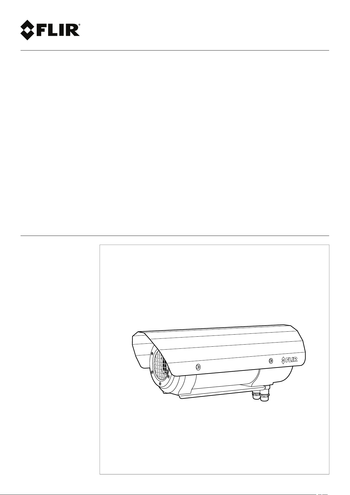
FLIR A310 ex
Page 2

Page 3

User’s manual
FLIR A310 ex
#T559891; r. AD/38469/38469; en-US
iii
Page 4

Page 5

Table of contents
1 Disclaimers ............ .. ..................................... .. ................................. 1
1.1 Legal disclaimer ....................................................................... 1
1.2 Usage statistics ........................................................................1
1.3 Changes to registry ...................................................................1
1.4 U.S. Government Regulations...................................................... 1
1.5 Copyright ................................................................................1
1.6 Quality assurance .....................................................................1
1.7 Patents...................................................................................1
1.8 EULA Terms ............................................................................1
1.9 EULA Terms ............................................................................1
2 Notice to user ......... .. ..................................... .. ................................. 3
2.1 User-to-user forums .................................................................. 3
2.2 Calibration...............................................................................3
2.3 Accuracy ................................................................................ 3
2.4 Disposal of electronic waste........................................................ 3
2.5 Training .................................................................................. 3
2.6 Documentation updates ............................................................. 3
2.7 Important note about this manual.................................................. 3
2.8 Note about authoritative versions..................................................3
3 Customer help .............. .. .. .. ............................... .. .. .. ......................... 4
3.1 General ..................................................................................4
3.2 Submitting a question ................................................................4
3.3 Downloads ..............................................................................5
4 Safety information .......... .. ..................................... .. ..........................6
5 What is FLIR A310 ex?..................................... .. ................................. 7
6 Typical system overview.......................... ..................................... .. ....8
7 Typical system setup procedure...................... ....................................9
8 Technical data ......... .. ..................................... .. ............................... 10
8.1 Online field-of-view calculator .................................................... 10
8.2 Note about technical data ......................................................... 10
8.3 Note about authoritative versions................................................ 10
8.4 FLIR A310 ex 25°.................................................................... 11
8.5 FLIR A310 ex 45°.................................................................... 14
9 Mechanical drawings .. .. ..................................... .............................. 17
10 EC Type Examination Certificate........................... .. ........................... 19
11 EC Type Examination Certificate, 1st supplement. ............................... 22
12 EC Type Examination Certificate, 3rd supplement . .............................. 25
13 EC Declaration of conformity (enclosure) ..................... .. .................... 28
14 Certiticate of conformity (camera) ..... ....................................... ......... 30
15 About FLIR Systems .................. .. ..................................... .. ............. 32
15.1 More than just an infrared camera .............................................. 33
15.2 Sharing our knowledge ............................................................ 33
15.3 Supporting our customers......................................................... 33
16 Glossary .... ..................................... .. ..................................... .. ...... 35
17 Thermographic measurement techniques .............................. .. .......... 38
17.1 Introduction .......................................................................... 38
17.2 Emissivity.............................................................................. 38
17.2.1 Finding the emissivity of a sample.................................... 38
17.3 Reflected apparent temperature ................................................. 41
17.4 Distance ............................................................................... 42
17.5 Relative humidity .................................................................... 42
17.6 Other parameters.................................................................... 42
#T559891; r. AD/38469/38469; en-US
v
Page 6

Table of contents
18 History of infrared technology................................. .. .. .. .................... 43
19 Theory of thermography.. .. ..................................... .. ........................ 46
19.1 Introduction ........................................................................... 46
19.2 The electromagnetic spectrum................................................... 46
19.3 Blackbody radiation................................................................. 46
19.3.1 Planck’s law ................................................................ 47
19.3.2 Wien’s displacement law................................................ 48
19.3.3 Stefan-Boltzmann's law ................................................. 49
19.3.4 Non-blackbody emitters................................................. 50
19.4 Infrared semi-transparent materials............................................. 52
20 The measurement formula....................... ..................................... .. .. 53
21 Emissivity tables ..................................... .. ..................................... . 57
21.1 References............................................................................ 57
21.2 Tables .................................................................................. 57
A OEM manual (German)....... .. .. .. ................................. .. .. .. ................. 68
B OEM manual (English) ....... .. ..................................... ....................... 92
#T559891; r. AD/38469/38469; en-US
vi
Page 7

1
Disclaimers
1.1 Legal disclaimer
All products manufactured by FLIR Systems are warranted against defective
materials and workmanship for a period of one (1) year from the delivery date
of the original purchase, provided such products have been under normal
storage, use and service, and in accordance with FLIR Systems instruction.
Uncooled handheld infrared cameras manufactured by FLIR Systems are
warranted against defective materials and workmanship for a period of two
(2) years from the delivery date of theoriginal purchase, provided such products have been under normal storage, use and service, and in accordance
with FLIR Systems instruction, and provided that the camera has been registered within 60 days of original purchase.
Detectors for uncooled handheld infrared cameras manufactured by FLIR
Systems are warranted against defective materials and workmanship for a
period of ten (10) years from the delivery date of the original purchase, provided such products have been under normal storage, use and service, and
in accordance with FLIR Systems instruction, and provided that the camera
has been registered within 60 days of original purchase.
Products which are not manufactured by FLIR Systems but included in systems delivered by FLIR Systems to the original purchaser, carry the warranty,
if any, of the particular supplier only. FLIR Systems has no responsibility
whatsoever for such products.
The warranty extends only to the original purchaser and is not transferable. It
is not applicable to any product which has been subjected to misuse, neglect,
accident or abnormal conditions of operation. Expendable partsare excluded
from the warranty.
In the case of a defect in a product covered by this warranty the product must
not be further used in order to prevent additional damage. The purchaser
shall promptly report any defect to FLIR Systems or this warranty will not
apply.
FLIR Systems will, at its option, repair or replace any such defective product
free of charge if, upon inspection, it proves to be defective in material or workmanship and provided that it is returned to FLIR Systems within the said oneyear period.
FLIR Systems has no other obligation or liability for defects than those set
forth above.
No other warranty is expressed or implied. FLIR Systems specifically disclaims the implied warranties of merchantability and fitness for a particular
purpose.
FLIR Systems shall not be liable for any direct, indirect, special, incidental or
consequential loss or damage, whether based on contract, tort or anyother
legal theory.
This warranty shall be governed by Swedish law.
Any dispute, controversy or claim arising out of or in connection with thiswar-
ranty, shall be finally settled by arbitration in accordance with the Rules of the
Arbitration Institute of the Stockholm Chamber of Commerce. The place of arbitration shall be Stockholm. The language to be used in thearbitral proceedings shall be English.
1.2 Usage statistics
FLIR Systems reserves the right to gather anonymous usage statistics to help
maintain and improve the quality of our software and services.
1.3 Changes to registry
The registry entry HKEY_LOCAL_MACHINE\SYSTEM\CurrentControlSet
\Control\Lsa\LmCompatibilityLevel will be automatically changed to level 2 if
the FLIR Camera Monitor service detects a FLIR camera connected to the
computer with a USB cable. The modification will only be executed if the
camera device implements a remote network service that supports network
logons.
1.4 U.S. Government Regulations
This product may be subject to U.S. Export Regulations. Please send any inquiries to exportquestions@flir.com.
1.5 Copyright
© 2016, FLIR Systems, Inc. All rights reserved worldwide. No parts of the
software including source code may be reproduced, transmitted, transcribed
or translated into any language or computer language in any form or by any
means, electronic, magnetic, optical, manual or otherwise, without the prior
written permission of FLIR Systems.
The documentation must not, in whole or part, be copied, photocopied,reproduced, translated or transmitted to any electronic mediumor machine
readable form without prior consent, in writing, from FLIR Systems.
Names and marks appearing on the products herein are either registered
trademarks or trademarks of FLIR Systems and/or its subsidiaries. All other
trademarks, trade names or company names referenced herein are used for
identification only and are the property of their respective owners.
1.6 Quality assurance
The Quality Management System under which these products are developed
and manufactured has been certified in accordance with the ISO 9001
standard.
FLIR Systems is committed to a policy of continuous development; therefore
we reserve the right to make changes andimprovements on any of the products without prior notice.
1.7 Patents
One or several of thefollowing patents and/or design patents may apply to
the products and/or features. Additional pending patents and/or pending design patents may also apply.
000279476-0001; 000439161; 000499579-0001; 000653423; 000726344;
000859020; 001106306-0001; 001707738; 001707746; 001707787;
001776519; 001954074; 002021543; 002058180; 002249953; 002531178;
0600574-8; 1144833; 1182246; 1182620; 1285345; 1299699; 1325808;
1336775; 1391114; 1402918; 1404291; 1411581; 1415075; 1421497;
1458284; 1678485; 1732314; 2106017; 2107799; 2381417; 3006596;
3006597; 466540; 483782; 484155; 4889913; 5177595; 60122153.2;
602004011681.5-08; 6707044; 68657; 7034300; 7110035; 7154093;
7157705; 7237946; 7312822; 7332716; 7336823; 7544944; 7667198;
7809258 B2; 7826736; 8,153,971; 8,823,803; 8,853,631; 8018649 B2;
8212210 B2; 8289372; 8354639 B2; 8384783; 8520970; 8565547; 8595689;
8599262; 8654239; 8680468; 8803093; D540838; D549758; D579475;
D584755; D599,392; D615,113; D664,580; D664,581; D665,004; D665,440;
D677298; D710,424 S; D718801; DI6702302-9; DI6903617-9; DI7002221-6;
DI7002891-5; DI7002892-3; DI7005799-0; DM/057692; DM/061609; EP
2115696 B1; EP2315433; SE 0700240-5; US 8340414 B2; ZL
201330267619.5; ZL01823221.3; ZL01823226.4; ZL02331553.9;
ZL02331554.7; ZL200480034894.0; ZL200530120994.2;
ZL200610088759.5; ZL200630130114.4; ZL200730151141.4;
ZL200730339504.7; ZL200820105768.8; ZL200830128581.2;
ZL200880105236.4; ZL200880105769.2; ZL200930190061.9;
ZL201030176127.1; ZL201030176130.3; ZL201030176157.2;
ZL201030595931.3; ZL201130442354.9; ZL201230471744.3;
ZL201230620731.8.
1.8 EULA Terms
• Youhave acquired a device (“INFRARED CAMERA”) that includes software licensed by FLIR Systems AB from Microsoft Licensing, GP or its
affiliates (“MS”). Those installed software products of MS origin, as well
as associated media, printed materials, and “online” or electronic documentation (“SOFTWARE”) are protected by international intellectual
property laws and treaties. The SOFTWARE is licensed, not sold. All
rights reserved.
• IF YOU DO NOT AGREE TO THIS END USER LICENSE AGREEMENT
(“EULA”), DO NOT USE THE DEVICE OR COPY THE SOFTWARE. INSTEAD, PROMPTLY CONTACT FLIR Systems AB FOR INSTRUCTIONS ON RETURN OF THE UNUSED DEVICE(S) FOR A REFUND.
ANY USE OF THE SOFTWARE, INCLUDING BUT NOT LIMITED TO
USE ON THE DEVICE, WILL CONSTITUTE YOUR AGREEMENT TO
THIS EULA (OR RATIFICATION OF ANY PREVIOUS CONSENT).
• GRANT OF SOFTWARE LICENSE. This EULAgrants you the following
license:
◦ Youmay use the SOFTWARE only on the DEVICE.
◦ NOT FAULT TOLERANT. THE SOFTWARE IS NOT FAULT TOL-
ERANT.FLIR SystemsAB HAS INDEPENDENTLYDETERMINED
HOW TO USE THE SOFTWARE IN THE DEVICE, AND MS HAS
RELIED UPON FLIR Systems AB TO CONDUCT SUFFICIENT
TESTING TO DETERMINE THAT THE SOFTWARE IS SUITABLE
FOR SUCH USE.
◦ NO WARRANTIES FOR THE SOFTWARE. THE SOFTWARE is
provided “AS IS” and with all faults. THE ENTIRE RISK AS TO
SATISFACTORY QUALITY, PERFORMANCE, ACCURACY, AND
EFFORT (INCLUDING LACK OF NEGLIGENCE) IS WITH YOU.
ALSO, THERE IS NO WARRANTYAGAINST INTERFERENCE
WITH YOUR ENJOYMENT OF THE SOFTWARE OR AGAINST
INFRINGEMENT.IF YOU HAVE RECEIVED ANY WARRANTIES
REGARDING THE DEVICE OR THE SOFTWARE, THOSE WARRANTIES DO NOT ORIGINATE FROM, AND ARE NOT BINDING
ON, MS.
◦ No Liability for Certain Damages. EXCEPT AS PROHIBITED BY
LAW,MS SHALL HAVE NO LIABILITY FOR ANY INDIRECT,
SPECIAL, CONSEQUENTIAL OR INCIDENTAL DAMAGES
ARISING FROM OR IN CONNECTION WITH THE USE OR PERFORMANCE OF THE SOFTWARE. THIS LIMITATION SHALL
APPLYEVEN IF ANY REMEDY FAILS OF ITS ESSENTIAL PURPOSE. IN NO EVENT SHALL MS BE LIABLE FOR ANY
AMOUNT IN EXCESS OF U.S. TWO HUNDRED FIFTY DOLLARS (U.S.$250.00).
◦ Limitations on Reverse Engineering, Decompilation, and Dis-
assembly. You may not reverse engineer, decompile, or disas-
semble the SOFTWARE, except and only to the extent that such
activity is expressly permitted by applicable law notwithstanding
this limitation.
◦ SOFTWARE TRANSFER ALLOWED BUT WITH RESTRIC-
TIONS. You may permanently transfer rights under this EULA only
as part of a permanent sale or transfer of the Device, and only if
the recipient agrees to this EULA. If the SOFTWARE is an upgrade, any transfer must also include all prior versions of the
SOFTWARE.
◦ EXPORT RESTRICTIONS. You acknowledge that SOFTWARE is
subject to U.S. export jurisdiction. You agree to comply with all applicable international and national laws that apply tothe SOFTWARE, including the U.S. Export AdministrationRegulations, as
well as end-user, end-use and destination restrictions issued by U.
S. and other governments. For additional information see http://
www.microsoft.com/exporting/.
1.9 EULA Terms
Qt4 Core and Qt4 GUI, Copyright ©2013 Nokia Corporation and FLIR Systems AB. This Qt library is a free software; you can redistribute it and/or modify it under the terms of the GNU Lesser General PublicLicense as published
by the Free Software Foundation; either version 2.1 of the License, or (at your
option) any later version. This library is distributed in the hope that it willbe
useful, but WITHOUT ANY WARRANTY; without even the implied warranty of
MERCHANTABILITYor FITNESS FOR A PARTICULAR PURPOSE. See the
GNU Lesser General Public License, http://www.gnu.org/licenses/lgpl-2.1.
#T559891; r. AD/38469/38469; en-US
1
Page 8

Disclaimers1
html. The source code for the libraries Qt4 Core and Qt4GUI may be requested from FLIR Systems AB.
#T559891; r. AD/38469/38469; en-US
2
Page 9

2
Notice to user
2.1 User-to-user forums
Exchange ideas, problems, and infrared solutions with fellow thermographers around the
world in our user-to-user forums. To go to the forums, visit:
http://www.infraredtraining.com/community/boards/
2.2 Calibration
We recommend that you send in the camera for calibration once a year. Contact your local sales office for instructions on where to send the camera.
2.3 Accuracy
For very accurate results, we recommend that you wait 5 minutes after you have started
the camera before measuring a temperature.
2.4 Disposal of electronic waste
As with most electronic products, this equipment must be disposed of in an environmentally friendly way, and in accordance with existing regulations for electronic waste.
Please contact your FLIR Systems representative for more details.
2.5 Training
To read about infrared training, visit:
• http://www.infraredtraining.com
• http://www.irtraining.com
• http://www.irtraining.eu
2.6 Documentation updates
Our manuals are updated several times per year, and we also issue product-critical notifications of changes on a regular basis.
To access the latest manuals, translations of manuals, and notifications, go to the Download tab at:
http://support.flir.com
It only takes a few minutes to register online. In the download area you will also find the
latest releases of manuals for our other products, as well as manuals for our historical
and obsolete products.
2.7 Important note about this manual
FLIR Systems issues generic manuals that cover several cameras within a model line.
This means that this manual may contain descriptions and explanations that do not apply
to your particular camera model.
2.8 Note about authoritative versions
The authoritative version of this publication is English. In the event of divergences due to
translation errors, the English text has precedence.
Any late changes are first implemented in English.
#T559891; r. AD/38469/38469; en-US
3
Page 10
3
Customer help
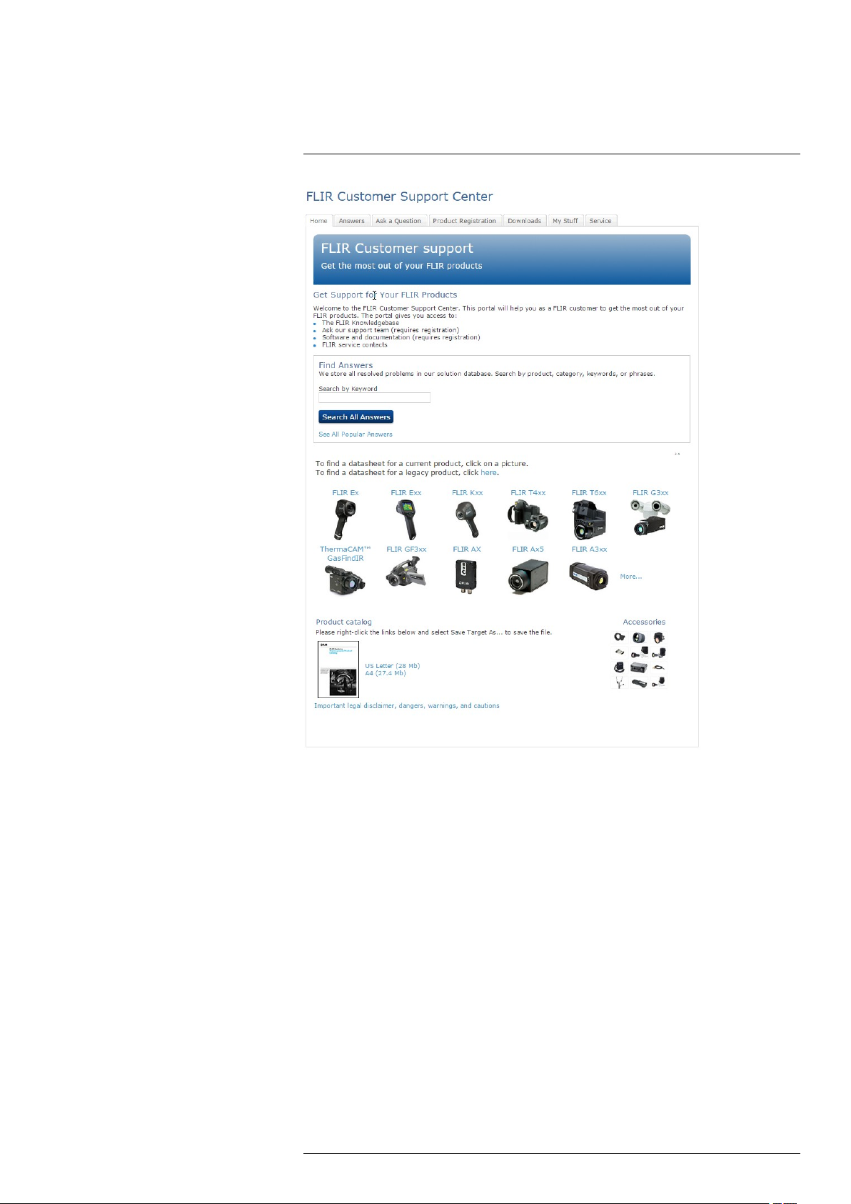
3.1 General
For customer help, visit:
http://support.flir.com
3.2 Submitting a question
To submit a question to the customer help team, you must be a registered user. It only
takes a few minutes to register online. If you only want to search the knowledgebase for
existing questions and answers, you do not need to be a registered user.
When you want to submit a question, make sure that you have the following information
to hand:
• The camera model
• The camera serial number
• The communication protocol, or method, between the camera and your device (for example, HDMI, Ethernet, USB, or FireWire)
• Device type (PC/Mac/iPhone/iPad/Android device, etc.)
• Version of any programs from FLIR Systems
• Full name, publication number, and revision number of the manual
#T559891; r. AD/38469/38469; en-US
4
Page 11

3
Customer help
3.3 Downloads
On the customer help site you can also download the following, when applicable for the
product:
• Firmware updates for your infrared camera.
• Program updates for your PC/Mac software.
• Freeware and evaluation versions of PC/Mac software.
• User documentation for current, obsolete, and historical products.
• Mechanical drawings (in *.dxf and *.pdf format).
• Cad data models (in *.stp format).
• Application stories.
• Technical datasheets.
• Product catalogs.
#T559891; r. AD/38469/38469; en-US
5
Page 12
4
Safety information
CAUTION
Do not point the infrared camera (with or without the lens cover) at strong energy sources, for example,
devices that cause laser radiation, or the sun. This can have an unwanted effect on the accuracy of the
camera. It can also cause damage to the detector in the camera.
CAUTION
Applicability: Cameras with an automatic shutter that can be disabled.
Do not disable the automatic shutter in the camera for a long time period (a maximum of 30 minutes is
typical). If you disable the shutter for a longer time period, damage to the detector can occur.
#T559891; r. AD/38469/38469; en-US
6
Page 13

5
What is FLIR A310 ex?
Explosive atmospheres need to be protected from ignition sources by selecting equipment and protective systems that meet the requirements of the ATEX product directives
and similar regulations.
The FLIR A310 ex is an ATEX-proof solution, with a thermal imaging camera mounted in
an enclosure, making it possible to monitor critical and other valuable assets in explosive
atmospheres. Process monitoring, quality control, and fire detection in potentially explosive locations are typical applications for the FLIR A310 ex.
Key features:
• Thermography monitoring and early fire detection in explosion hazard areas.
• Enclosures for infrared cameras in classification zones 1, 2, 21, and 22.
• ATEX certified to the latest standards.
• Rated to protection class IP67.
• Plug and play installation, with the enclosure delivered ready for use.
#T559891; r. AD/38469/38469; en-US
7
Page 14
6
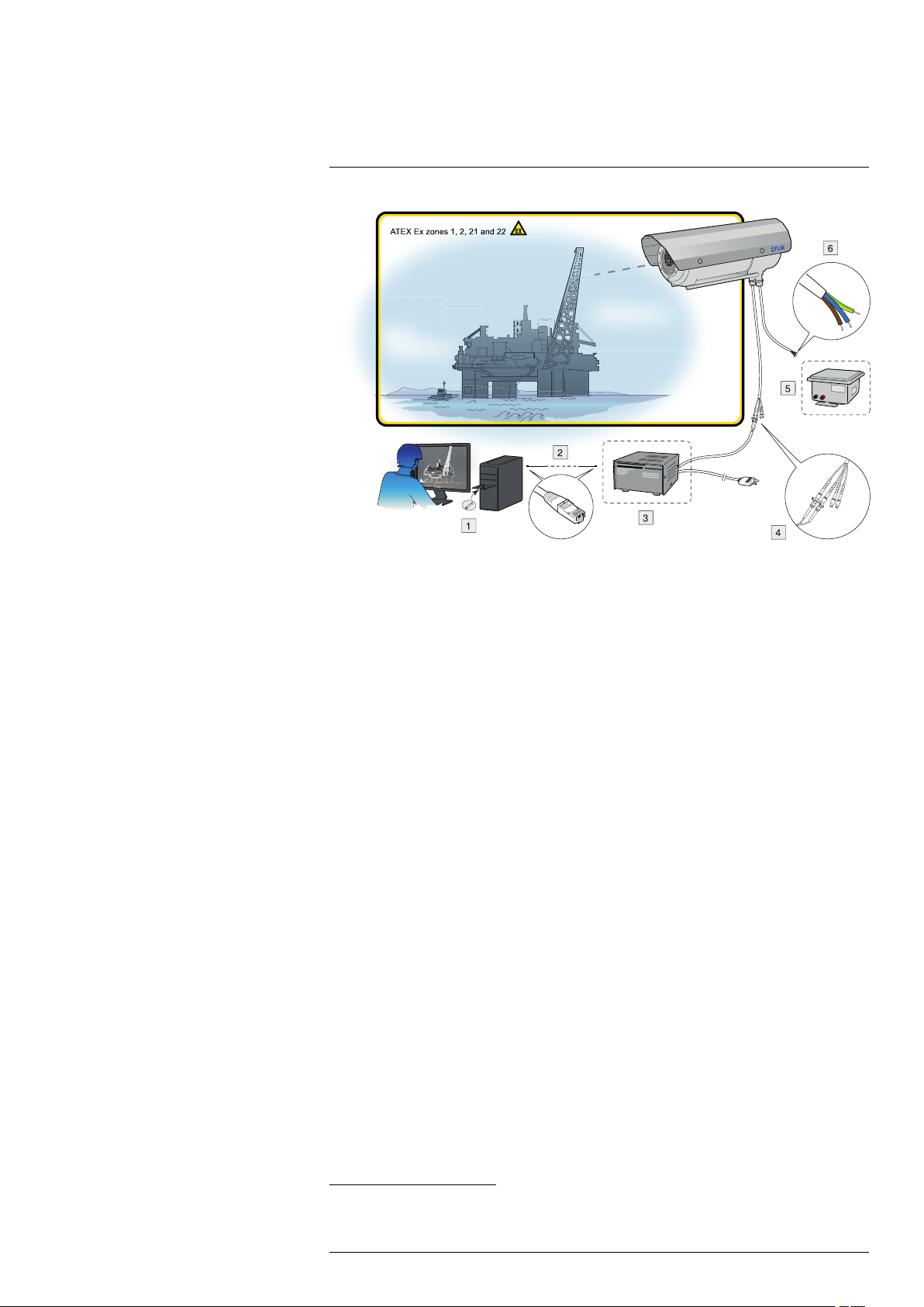
Typical system overview
1. Thermovision System Tools & Utilities CD-ROM.
2. Ethernet cable.
3. Optical-to-Ethernet converter.
4. FC connectors from the camera housing (including two spares).
5. 24 V DC power supply.
6. Pigtail cable from the housing. The color coding of the pigtail cable is:
• Brown: positive (+).
• Blue: negative (–).
• Green/yellow: earth.
1
1
1
1. Not supplied with the camera unit.
#T559891; r. AD/38469/38469; en-US
8
Page 15

7
Typical system setup procedure
1. Unpack the camera unit from the cardboard box.
2. Install the camera unit at the intended location. It is the responsibility of the installer
to meet all applicable safety standards required by the authorities of the region in
which the unit will be operating in.
3. Connect the camera unit to an external power supply.
The color coding of the pigtail cable is:
• Brown: positive +.
• Blue: negative –.
• Green/yellow: earth.
Note The external power supply must not be inside the classified zone.
4. Connect the camera unit to an optical-to-Ethernet converter.
Note The optical-to-Ethernet converter must not be inside the classified zone.
5. Install the Thermovision System Tools & Utilities CD-ROM on a computer connected
to the network. This will install the following software:
• FLIR IP Config.
• FLIR IR Monitor.
• FLIR IR Camera Player.
6. Start FLIR IP Config to identify the unit in the network and automatically assign or
manually set IP addresses, etc. For more information, see the FLIR IP Config manual
on the User Documentation CD-ROM or on the Help menu in FLIR IP Config.
7. Start FLIR IR Monitor to control the camera, e.g., laying out measurement tools and
setting up alarms. For more information, see the FLIR IR Monitor manual on the User
Documentation CD-ROM or on the Help menu in FLIR IR Monitor.
2
The unit requires 24 V DC in.
2
2. Not supplied with the camera unit.
#T559891; r. AD/38469/38469; en-US
9
Page 16

8
Technical data
8.1 Online field-of-view calculator
Please visit http://support.flir.com and click the photo of the camera series for field-ofview tables for all lens–camera combinations.
8.2 Note about technical data
FLIR Systems reserves the right to change specifications at any time without prior notice.
Please check http://support.flir.com for latest changes.
8.3 Note about authoritative versions
The authoritative version of this publication is English. In the event of divergences due to
translation errors, the English text has precedence.
Any late changes are first implemented in English.
#T559891; r. AD/38469/38469; en-US
10
Page 17

Technical data8
8.4 FLIR A310 ex 25°
P/N: 71001-1103
Rev.: 38447
Introduction
The FLIR A310 ex is an ATEX-proof solution, with a thermal imaging camera mounted in
an enclosure—making it possible to monitor critical and other valuable assets in explosive atmospheres. Process monitoring, quality control, and fire detection in potentially
explosive locations are typical applications for the FLIR A310 ex.
• Thermographic monitoring and early fire detection in an explosion–hazard area.
• Enclosures for infrared cameras in Ex zones 1, 2, 21, 22.
• ATEX certified.
• Protection class IP67.
• Plug-and-play installation with the enclosure delivered ready for use.
• Available with additional options.
The certification covers the entire system, which includes the enclosure as well as all
components inside of it, such as the infrared camera, heater, and integrated controller.
This means that no additional certification is required for operation.
The integrated controller is equipped with two fiber optic and two Ethernet ports. This enables a flexible network integration in star ring topologies.
In addition, the integrated controller features several digital I/O channels and sensors for
temperature, humidity, and pressure. Among other functions, the I/O channels enable
the user to switch on/off the camera and the heater via remote control. Access is through
an integrated web interface or Modbus TCP/IP.
Explosion-proof housing
General data
Ambient temperature range for operation –40°C to +60°C (–40°F to +140°F)
Protection class IP67
Weight 6.7 kg (without camera and lens)
Empty volume 5.06 l
External dimensions (without sun shield) D = 170 mm, L = 408 mm
Housing material Nickel-plated aluminium
Surface Powder coated
Protection window
Maximum power of the additional heater 16 W
Operating voltage 24 V DC
Maximum electric connection power 60 W
Power cable Helukabel 37264
Length of power cable 4 m (13 ft.)
Power cable configuration Pigtail
Integrated controller 4-port switch with 2 × fiber-optic LC 100Base-FX
Ethernet medium
Length of Ethernet cable 4 m (13 ft.)
Ethernet configuration Pigtail with FC connector
Germanium, double-sided AR Coated, externally
with additional hard-carbon layer
or 2 × RJ45(10/100) up-links, ring-topology support for reduced cabling effort, 2 × internal temperature sensors, air humidity and pressure
sensor, digital output module controllable via
Modbus TCP/IP or web interface to enable turning
the heater on/off
Multi-mode breakout fiber AT-V(ZN)Y(ZN)Y 4G50/
125 OM2
#T559891; r. AD/38469/38469; en-US
11
Page 18

Technical data8
Explosion protection-specific data
For use in EX zone 1, 2, 21, 22
Ignition protection category Flame-proof enclosure “d”
Maximum surface temperature (according to temperature class T6)
ATEX certification (version -AXC)
Verification certificate ZELM 12 ATEX 0485 X
Maximum 85°C
• II 2G Ex db IIC T6 / T5
• II 2D Ex tb IIIC T85° / T100
Camera system
Imaging and optical data
IR resolution 320 × 240 pixels
Thermal sensitivity/NETD < 0.05°C @ +30°C (+86°F) / 50 mK
Field of view (FOV)
Minimum focus distance 0.4 m (1.31 ft.)
Focal length 18 mm (0.7 in.)
Spatial resolution (IFOV)
Lens identification Automatic
F-number 1.3
Image frequency 30 Hz
Focus Automatic or manual (built in motor)
Zoom 1–8× continuous, digital, interpolating zooming on
25° × 18.8°
1.36 mrad
images
Detector data
Detector type Focal plane array (FPA), uncooled
Spectral range
Detector pitch 25 µm
Detector time constant Typical 12 ms
Measurement
Object temperature range
Accuracy ±4°C (±7.2°F) or ±2% of reading
Measurement analysis
Spotmeter
Area 10 boxes with max./min./average/position
Isotherm
Measurement option Measurement Mask Filter
Difference temperature Delta temperature between measurement func-
Reference temperature Manually set or captured from any measurement
Atmospheric transmission correction Automatic, based on inputs for distance, atmos-
Optics transmission correction Automatic, based on signals from internal sensors
microbolometer
7.5–13 µm
• –20 to +120°C (–4 to +248°F)
• 0 to +350°C (+32 to +662°F)
10
1 with above/below/interval
Schedule response: File sending (ftp), email
(SMTP)
tions or reference temperature
function
pheric temperature and relative humidity
#T559891; r. AD/38469/38469; en-US
12
Page 19

Technical data8
Measurement analysis
Emissivity correction Variable from 0.01 to 1.0
Reflected apparent temperature correction Automatic, based on input of reflected
External optics/windows correction Automatic, based on input of optics/window trans-
Measurement corrections Global and individual object parameters
Alarm
Alarm functions 6 automatic alarms on any selected measurement
Alarm output Digital Out, log, store image, file sending (ftp),
Set-up
Color palettes Color palettes (BW, BW inv, Iron, Rain)
Set-up commands Date/time, Temperature (°C/°F)
temperature
mission and temperature
function, Digital In, Camera temperature, timer
email (SMTP), notification
Storage of images
Storage media Built-in memory for image storage
File formats Standard JPEG, 16-bit measurement data
Ethernet
Ethernet Control, result and image
Ethernet, type 100 Mbps
Ethernet, standard IEEE 802.3
Ethernet, configuration Pigtail with FC-connector (fiber)
Ethernet, communication
Ethernet, video streaming
Ethernet, image streaming 16-bit 320 × 240 pixels @ 7-8 Hz
Ethernet, protocols Ethernet/IP, Modbus TCP, TCP, UDP, SNTP, RTSP,
Shipping information
Packaging, type Cardboard box
List of contents
Packaging, weight
Packaging, size 495 × 370 × 192 mm (19.5 × 14.6 × 7.6 in.)
EAN-13 7332558008355
UPC-12
Country of origin Sweden
included
TCP/IP socket-based FLIR proprietary
MPEG-4, ISO/IEC 14496-1 MPEG-4 ASP@L5
• Radiometric
RTP, HTTP, ICMP, IGMP, ftp, SMTP, SMB (CIFS),
DHCP, MDNS (Bonjour), uPnP
• Infrared camera with lens, in explosion-proof
housing
• Printed documentation
• Utility CD-ROM
845188008703
Supplies & accessories
• T911263ACC; Wall mount kit
• T911288ACC; Pole mount adapter for wall mount kit
#T559891; r. AD/38469/38469; en-US
13
Page 20

Technical data8
8.5 FLIR A310 ex 45°
P/N: 71001-1104
Rev.: 38447
Introduction
The FLIR A310 ex is an ATEX-proof solution, with a thermal imaging camera mounted in
an enclosure—making it possible to monitor critical and other valuable assets in explosive atmospheres. Process monitoring, quality control, and fire detection in potentially
explosive locations are typical applications for the FLIR A310 ex.
• Thermographic monitoring and early fire detection in an explosion–hazard area.
• Enclosures for infrared cameras in Ex zones 1, 2, 21, 22.
• ATEX certified.
• Protection class IP67.
• Plug-and-play installation with the enclosure delivered ready for use.
• Available with additional options.
The certification covers the entire system, which includes the enclosure as well as all
components inside of it, such as the infrared camera, heater, and integrated controller.
This means that no additional certification is required for operation.
The integrated controller is equipped with two fiber optic and two Ethernet ports. This enables a flexible network integration in star ring topologies.
In addition, the integrated controller features several digital I/O channels and sensors for
temperature, humidity, and pressure. Among other functions, the I/O channels enable
the user to switch on/off the camera and the heater via remote control. Access is through
an integrated web interface or Modbus TCP/IP.
Explosion-proof housing
General data
Ambient temperature range for operation –40°C to +60°C (–40°F to +140°F)
Protection class IP67
Weight 6.7 kg (without camera and lens)
Empty volume 5.06 l
External dimensions (without sun shield) D = 170 mm, L = 408 mm
Housing material Nickel-plated aluminium
Surface Powder coated
Protection window
Maximum power of the additional heater 16 W
Operating voltage 24 V DC
Maximum electric connection power 60 W
Power cable Helukabel 37264
Length of power cable 4 m (13 ft.)
Power cable configuration Pigtail
Integrated controller 4-port switch with 2 × fiber-optic LC 100Base-FX
Ethernet medium
Length of Ethernet cable 4 m (13 ft.)
Ethernet configuration Pigtail with FC connector
Germanium, double-sided AR Coated, externally
with additional hard-carbon layer
or 2 × RJ45(10/100) up-links, ring-topology support for reduced cabling effort, 2 × internal temperature sensors, air humidity and pressure
sensor, digital output module controllable via
Modbus TCP/IP or web interface to enable turning
the heater on/off
Multi-mode breakout fiber AT-V(ZN)Y(ZN)Y 4G50/
125 OM2
#T559891; r. AD/38469/38469; en-US
14
Page 21

Technical data8
Explosion protection-specific data
For use in EX zone 1, 2, 21, 22.
Ignition protection category Flame-proof enclosure “d”
Maximum surface temperature (according to temperature class T6)
ATEX certification (version -AXC)
Verification certificate ZELM 12 ATEX 0485 X
Maximum 85°C
• II 2G Ex db IIC T6 / T5
• II 2D Ex tb IIIC T85° / T100
Camera system
Imaging and optical data
IR resolution 320 × 240 pixels
Thermal sensitivity/NETD < 0.05°C @ +30°C (+86°F) / 50 mK
Field of view (FOV)
Minimum focus distance 0.20 m (0.66 ft.)
Focal length 9.66 mm (0.38 in.)
Spatial resolution (IFOV)
Lens identification Automatic
F-number 1.3
Image frequency 30 Hz
Focus Automatic or manual (built in motor)
Zoom 1–8× continuous, digital, interpolating zooming on
45° × 33.8
2.59 mrad
images
Detector data
Detector type Focal plane array (FPA), uncooled
Spectral range
Detector pitch 25 µm
Detector time constant Typical 12 ms
Measurement
Object temperature range
Accuracy ±4°C (±7.2°F) or ±2% of reading
Measurement analysis
Spotmeter
Area 10 boxes with max./min./average/position
Isotherm
Measurement option Measurement Mask Filter
Difference temperature Delta temperature between measurement func-
Reference temperature Manually set or captured from any measurement
Atmospheric transmission correction Automatic, based on inputs for distance, atmos-
Optics transmission correction Automatic, based on signals from internal sensors
microbolometer
7.5–13 µm
• –20 to +120°C (–4 to +248°F)
• 0 to +350°C (+32 to +662°F)
10
1 with above/below/interval
Schedule response: File sending (ftp), email
(SMTP)
tions or reference temperature
function
pheric temperature and relative humidity
#T559891; r. AD/38469/38469; en-US
15
Page 22

Technical data8
Measurement analysis
Emissivity correction Variable from 0.01 to 1.0
Reflected apparent temperature correction Automatic, based on input of reflected
External optics/windows correction Automatic, based on input of optics/window trans-
Measurement corrections Global and individual object parameters
Alarm
Alarm functions 6 automatic alarms on any selected measurement
Alarm output Digital Out, log, store image, file sending (ftp),
Set-up
Color palettes Color palettes (BW, BW inv, Iron, Rain)
Set-up commands Date/time, Temperature (°C/°F)
temperature
mission and temperature
function, Digital In, Camera temperature, timer
email (SMTP), notification
Storage of images
Storage media Built-in memory for image storage
File formats Standard JPEG, 16-bit measurement data
Ethernet
Ethernet Control, result and image
Ethernet, type 100 Mbps
Ethernet, standard IEEE 802.3
Ethernet, configuration Pigtail with FC connector
Ethernet, communication
Ethernet, video streaming
Ethernet, image streaming 16-bit 320 × 240 pixels @ 7-8 Hz
Ethernet, protocols Ethernet/IP, Modbus TCP, TCP, UDP, SNTP, RTSP,
Shipping information
Packaging, type Cardboard box
List of contents
Packaging, weight
Packaging, size 495 × 370 × 192 mm (19.5 × 14.6 × 7.6 in.)
EAN-13 7332558008362
UPC-12
Country of origin Sweden
included
TCP/IP socket-based FLIR proprietary
MPEG-4, ISO/IEC 14496-1 MPEG-4 ASP@L5
• Radiometric
RTP, HTTP, ICMP, IGMP, ftp, SMTP, SMB (CIFS),
DHCP, MDNS (Bonjour), uPnP
• Infrared camera with lens, in explosion-proof
housing
• Printed documentation
• Utility CD-ROM
845188008710
Supplies & accessories
• T911263ACC; Wall mount kit
• T911288ACC; Pole mount adapter for wall mount kit
#T559891; r. AD/38469/38469; en-US
16
Page 23

9
Mechanical drawings
#T559891; r. AD/38469/38469; en-US
17
Page 24
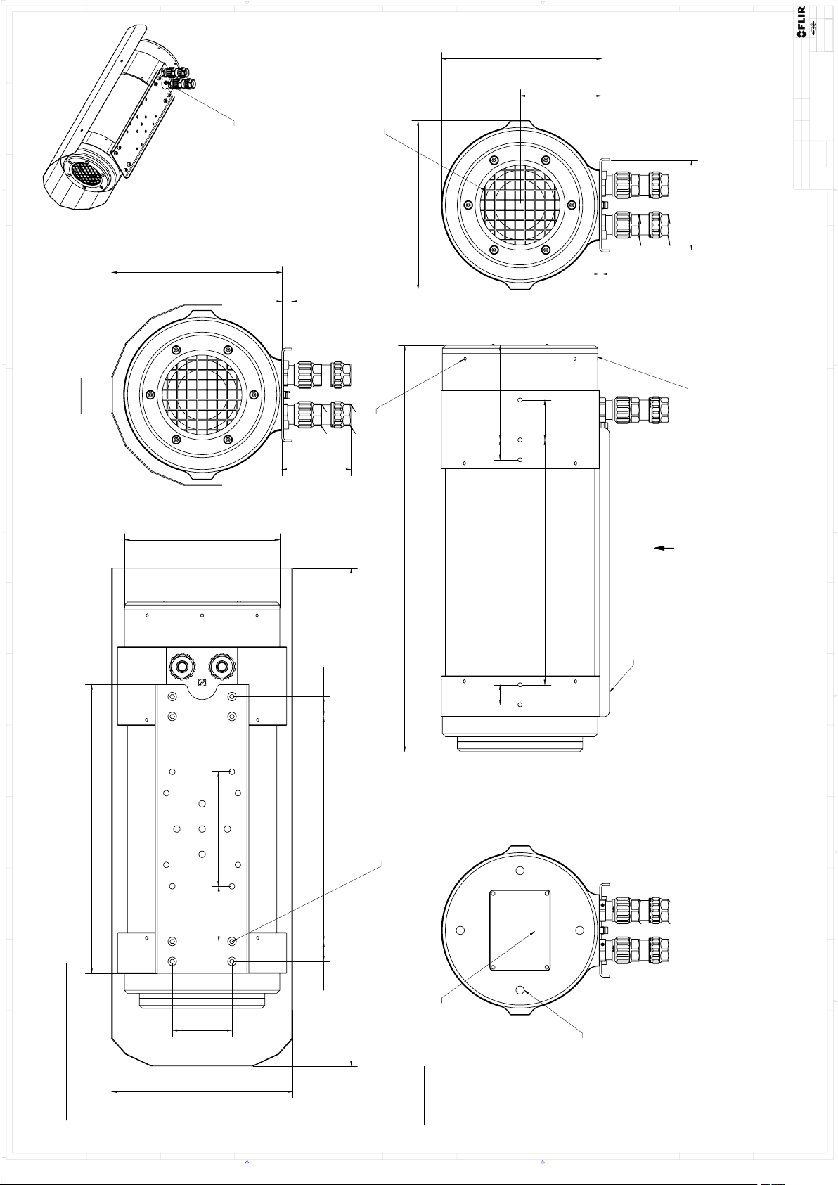
408,20
156,00
60,00
20,00 226,00
170,00
40,00
20,0020,00 95,00
246,00
82,00
2,00
55,50
20,00
115,00
161,00
90,00
290,00
500,00
182,00
171,00
10,00
70mm depending on
EX cable gland
A
A ( 1 : 2 )
Type
label
Mounting
rail
Protective
grid
8x Mounting holes with
M5x8 deep
for Mounting rail or
mounting plate
Overview with Sunshield
installed
Drawing without
Sunshield
Earthing
connection
Hole for
installation
wrench
4x Clamping
screws
Index
screw
All dimensions in
mm
Denna handling får ej delges annan, kopieras i
sin helhet eller delar utan vårt medgivande .
Överträdelse härav beivras med stöd av gällande lag.
FLIR SYSTEMS AB
This document must not be communicated or
copied completely or in part, without our permission.
Any infringement will lead to legal proceedings.
FLIR SYSTEMS AB
Där ej annat anges/Unless otherwise stated
Kanter brutna
Edges broken
Hålkälsradier
Fillet radii
Ytjämnhet/Roughness
Blad/Sheet
Rev
Ritn nr/Drawing No
Art.No.
Skala/Scale
Size
Datum/Date
Kontr/Check
Konstr/Drawn
Material
Ytbehandling/Surface treatment
Gen tol
Benämning/Denomination
A0
Utdrag ur/Excerpt from
ISO 2768-m
±0,1
±0,2
±0,3
±0,5
±0,8
(400)-1000
(120)-400
(30)-120
(6)-30
0,5-6
ISO 2768-mK
1(1)
2:1
H. ÖSTLING
A
T128183
A3xxEx
Basic Dimensions
JAMA
2014-04-14
2014-05-15
H. ÖSTLING
Ändrad av/Modified by
Ändrad/Modified
Ra µm
1 2 3 4 5 6 7 8 9 10 11 12 13 14 15 16
101 11732 1284 1395 6
A
B
C
D
E
F
G
H
I
J
K
B
J
F
G
C
H
D
A
I
E
K
-
Page 25

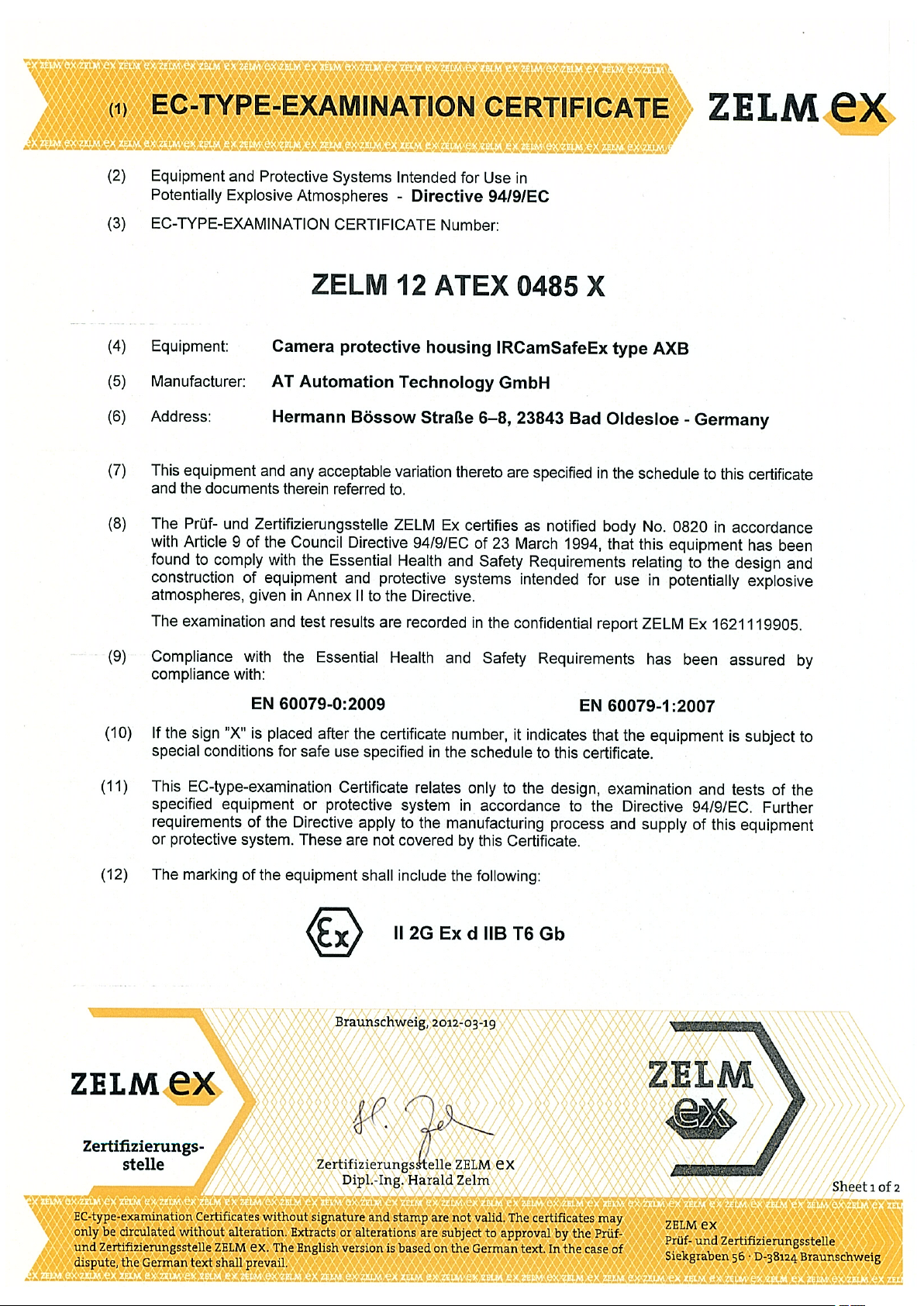
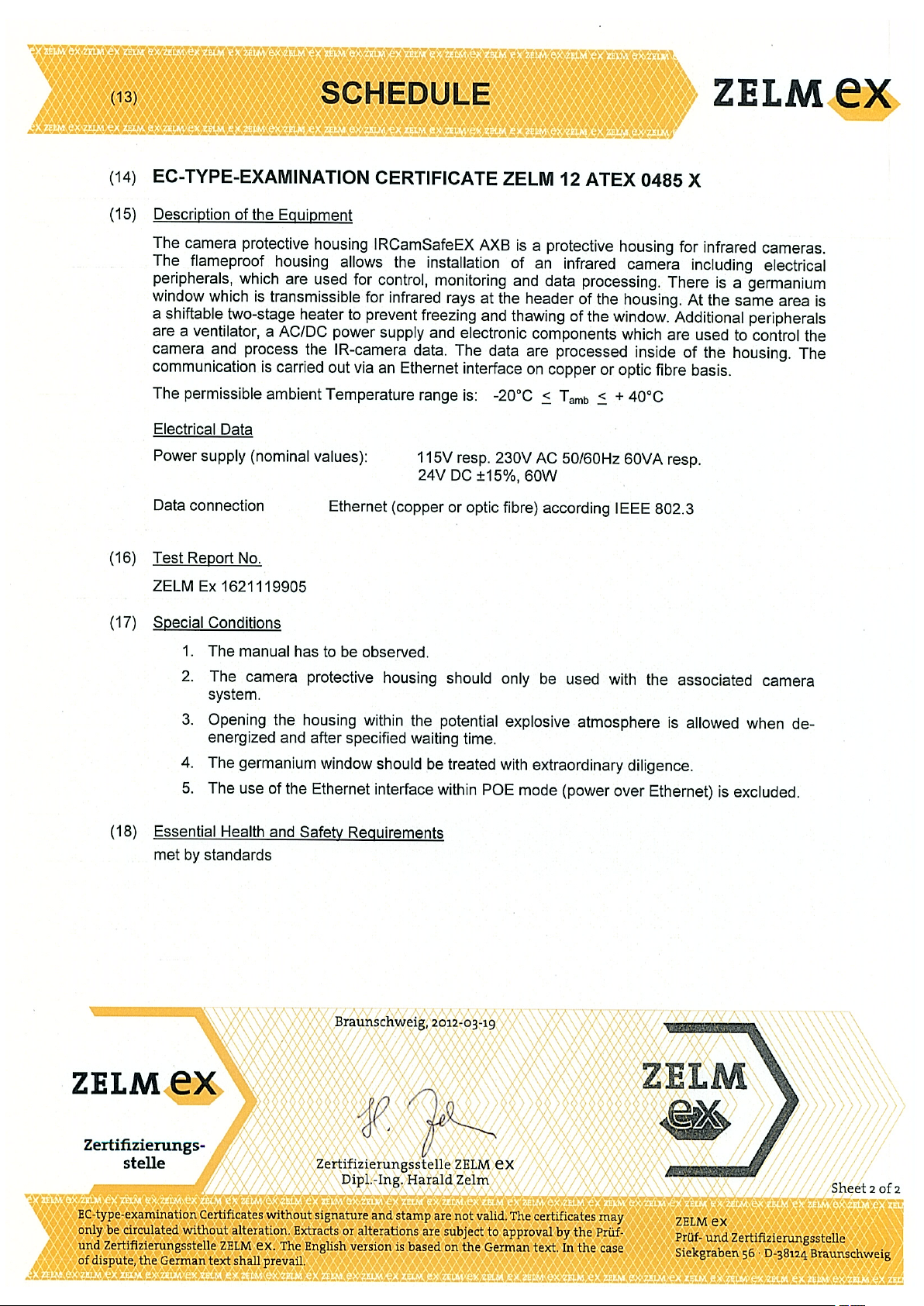
10
EC Type Examination Certificate
#T559891; r. AD/38469/38469; en-US
19
Page 26
Page 27
Page 28

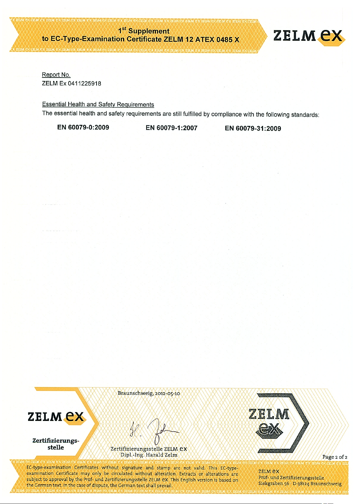
11
EC Type Examination Certificate, 1st supplement
#T559891; r. AD/38469/38469; en-US
22
Page 29

Page 30
Page 31

12
EC Type Examination Certificate, 3rd supplement
#T559891; r. AD/38469/38469; en-US
25
Page 32

Page 33

Page 34

13
EC Declaration of conformity (enclosure)
#T559891; r. AD/38469/38469; en-US
28
Page 35

EG-Konformitätserklärung
EC-Declaration of Conformity
Déclaration de Conformité CE
AT – Automation Technology GmbH • Hermann-Bössow-Strasse 6 – 8 • D-23843 Bad Oldesloe, Germany
erklärt in alleiniger Verantwortung,
declares in its sole responsibility,
déclare sous sa seule responsabilité
dass das Produkt
that the product
que le produit
IRCamSafeEX-AXB
IRCamSafeEX-AXC
Kennzeichnung, marking, marquage (-AXB):
Kennzeichnung, marking, marquage (-AXC):
II 2G Ex d IIB T6 Gb
II 2G Ex d IIC T6 Gb
II 2D Ex tb IIIC T85° Db
mit der EG-Baumusterprüfbescheinigung:
under EC-Type Examination Certificate:
avec Attestation d’examen CE de type:
ZELM 12 ATEX 0485 X
(ZELM Ex e.K.
Siekgraben 56, 38124 Braunschweig)
Kenn-Nr. der benannten Stelle:
Notified Body number:
No de l’organisme de certification:
0820
auf das sich diese Erklärung bezieht, mit den folgenden Normen oder normativen Dokumenten übereinstimmt
which is the subject of this declaration, is in conformity with the following standards or normative documents
auquel cette déclaration se rapporte, est conforme aux normes ou aux documents normatifs suivants
Bestimmungen der Richtlinie
Terms of the directive
Prescription de la directive
Nummer sowie Ausgabedatum der Norm
Number and date of issue of the standard
Numéro ainsi que date d’émission de la norme
94/9/EG: ATEX-Richtlinie
94/9/EC: ATEX Directive
94/9/CE: Directive ATEX
EN 60079-0: 2009
EN 60079-1: 2007
EN 60079-14: 2009
EN 60079-17: 2008
EN 60079-28: 2007
EN 60079-31: 2009
2006/95/EG: Niederspannungsrichtlinie
2006/95/EC: Low Voltage Directive
2006/95/CE: Directive Basse Tension
2004/108/EG: EMV-Richtlinie
2004/108/EC: EMC Directive
2004/108/CE: Directive CEM
Bad Oldesloe, 16. Mai. 2012
Ort und Datum
Place and Date
Lieu et date
Dr. Andrè Kasper
Leiter Qualitätssicherung
Director Quality Management Dept.
Directeur Dept. Assurance de Qualité
Page 36

14
Certiticate of conformity (camera)
#T559891; r. AD/38469/38469; en-US
30
Page 37

Page 38

15
About FLIR Systems
FLIR Systems was established in 1978 to pioneer the development of high-performance
infrared imaging systems, and is the world leader in the design, manufacture, and marketing of thermal imaging systems for a wide variety of commercial, industrial, and government applications. Today, FLIR Systems embraces five major companies with
outstanding achievements in infrared technology since 1958—the Swedish AGEMA Infrared Systems (formerly AGA Infrared Systems), the three United States companies Indigo Systems, FSI, and Inframetrics, and the French company Cedip.
Since 2007, FLIR Systems has acquired several companies with world-leading expertise
in sensor technologies:
• Extech Instruments (2007)
• Ifara Tecnologías (2008)
• Salvador Imaging (2009)
• OmniTech Partners (2009)
• Directed Perception (2009)
• Raymarine (2010)
• ICx Technologies (2010)
• TackTick Marine Digital Instruments (2011)
• Aerius Photonics (2011)
• Lorex Technology (2012)
• Traficon (2012)
• MARSS (2013)
• DigitalOptics micro-optics business (2013)
• DVTEL (2015)
• Point Grey Research (2016)
Figure 15.1 Patent documents from the early 1960s
FLIR Systems has three manufacturing plants in the United States (Portland, OR, Boston, MA, Santa Barbara, CA) and one in Sweden (Stockholm). Since 2007 there is also a
manufacturing plant in Tallinn, Estonia. Direct sales offices in Belgium, Brazil, China,
France, Germany, Great Britain, Hong Kong, Italy, Japan, Korea, Sweden, and the USA
—together with a worldwide network of agents and distributors—support our international customer base.
#T559891; r. AD/38469/38469; en-US
32
Page 39

15
About FLIR Systems
FLIR Systems is at the forefront of innovation in the infrared camera industry. We anticipate market demand by constantly improving our existing cameras and developing new
ones. The company has set milestones in product design and development such as the
introduction of the first battery-operated portable camera for industrial inspections, and
the first uncooled infrared camera, to mention just two innovations.
Figure 15.2 1969: Thermovision Model 661. The
camera weighed approximately 25 kg (55 lb.), the
oscilloscope 20 kg (44 lb.), and the tripod 15 kg
(33 lb.). The operator also needed a 220 VAC
generator set, and a 10 L (2.6 US gallon) jar with
liquid nitrogen. To the left of the oscilloscope the
Polaroid attachment (6 kg/13 lb.) can be seen.
Figure 15.3 2015: FLIR One, an accessory to
iPhone and Android mobile phones. Weight: 90 g
(3.2 oz.).
FLIR Systems manufactures all vital mechanical and electronic components of the camera systems itself. From detector design and manufacturing, to lenses and system electronics, to final testing and calibration, all production steps are carried out and
supervised by our own engineers. The in-depth expertise of these infrared specialists ensures the accuracy and reliability of all vital components that are assembled into your infrared camera.
15.1 More than just an infrared camera
At FLIR Systems we recognize that our job is to go beyond just producing the best infrared camera systems. We are committed to enabling all users of our infrared camera systems to work more productively by providing them with the most powerful camera–
software combination. Especially tailored software for predictive maintenance, R & D,
and process monitoring is developed in-house. Most software is available in a wide variety of languages.
We support all our infrared cameras with a wide variety of accessories to adapt your
equipment to the most demanding infrared applications.
15.2 Sharing our knowledge
Although our cameras are designed to be very user-friendly, there is a lot more to thermography than just knowing how to handle a camera. Therefore, FLIR Systems has
founded the Infrared Training Center (ITC), a separate business unit, that provides certified training courses. Attending one of the ITC courses will give you a truly hands-on
learning experience.
The staff of the ITC are also there to provide you with any application support you may
need in putting infrared theory into practice.
15.3 Supporting our customers
FLIR Systems operates a worldwide service network to keep your camera running at all
times. If you discover a problem with your camera, local service centers have all the
#T559891; r. AD/38469/38469; en-US
33
Page 40

15
About FLIR Systems
equipment and expertise to solve it within the shortest possible time. Therefore, there is
no need to send your camera to the other side of the world or to talk to someone who
does not speak your language.
#T559891; r. AD/38469/38469; en-US
34
Page 41

16
Glossary
absorption
(absorption
factor)
atmosphere The gases between the object being measured and the camera, nor-
autoadjust A function making a camera perform an internal image correction.
autopalette The IR image is shown with an uneven spread of colors, displaying
blackbody Totally non-reflective object. All its radiation is due to its own
blackbody
radiator
calculated atmospheric
transmission
cavity radiator A bottle shaped radiator with an absorbing inside, viewed through
color
temperature
conduction The process that makes heat diffuse into a material.
continuous
adjust
convection
dual isotherm An isotherm with two color bands, instead of one.
emissivity
(emissivity
factor)
emittance Amount of energy emitted from an object per unit of time and area
environment
estimated atmospheric
transmission
external optics Extra lenses, filters, heat shields etc. that can be put between the
filter A material transparent only to some of the infrared wavelengths.
FOV Field of view: The horizontal angle that can be viewed through an IR
FPA Focal plane array: A type of IR detector.
graybody An object that emits a fixed fraction of the amount of energy of a
IFOV Instantaneous field of view: A measure of the geometrical resolution
The amount of radiation absorbed by an object relative to the received radiation. A number between 0 and 1.
mally air.
cold objects as well as hot ones at the same time.
temperature.
An IR radiating equipment with blackbody properties used to cali-
brate IR cameras.
A transmission value computed from the temperature, the relative
humidity of air and the distance to the object.
the bottleneck.
The temperature for which the color of a blackbody matches a spe-
cific color.
A function that adjusts the image. The function works all the time,
continuously adjusting brightness and contrast according to the image content.
Convection is a heat transfer mode where a fluid is brought into motion, either by gravity or another force, thereby transferring heat from
one place to another.
The amount of radiation coming from an object, compared to that of
a blackbody. A number between 0 and 1.
2
(W/m
)
Objects and gases that emit radiation towards the object being
measured.
A transmission value, supplied by a user, replacing a calculated one
camera and the object being measured.
lens.
blackbody for each wavelength.
of an IR camera.
#T559891; r. AD/38469/38469; en-US
35
Page 42

16
Glossary
image correction (internal or
A way of compensating for sensitivity differences in various parts of
live images and also of stabilizing the camera.
external)
infrared Non-visible radiation, having a wavelength from about 2–13 μm.
IR infrared
isotherm A function highlighting those parts of an image that fall above, below
or between one or more temperature intervals.
isothermal
cavity
A bottle-shaped radiator with a uniform temperature viewed through
the bottleneck.
Laser LocatIR An electrically powered light source on the camera that emits laser
radiation in a thin, concentrated beam to point at certain parts of the
object in front of the camera.
laser pointer An electrically powered light source on the camera that emits laser
radiation in a thin, concentrated beam to point at certain parts of the
object in front of the camera.
level The center value of the temperature scale, usually expressed as a
signal value.
manual adjust A way to adjust the image by manually changing certain parameters.
NETD Noise equivalent temperature difference. A measure of the image
noise level of an IR camera.
noise Undesired small disturbance in the infrared image
object
parameters
A set of values describing the circumstances under which the meas-
urement of an object was made, and the object itself (such as emis-
sivity, reflected apparent temperature, distance etc.)
object signal A non-calibrated value related to the amount of radiation received by
the camera from the object.
palette The set of colors used to display an IR image.
pixel
Stands for picture element. One single spot in an image.
radiance Amount of energy emitted from an object per unit of time, area and
2
/sr)
radiant power
angle (W/m
Amount of energy emitted from an object per unit of time (W)
radiation The process by which electromagnetic energy, is emitted by an ob-
ject or a gas.
radiator A piece of IR radiating equipment.
range
The current overall temperature measurement limitation of an IR
camera. Cameras can have several ranges. Expressed as two
blackbody temperatures that limit the current calibration.
reference
temperature
A temperature which the ordinary measured values can be com-
pared with.
reflection The amount of radiation reflected by an object relative to the re-
ceived radiation. A number between 0 and 1.
relative
humidity
Relative humidity represents the ratio between the current water va-
pour mass in the air and the maximum it may contain in saturation
conditions.
saturation
color
The areas that contain temperatures outside the present level/span
settings are colored with the saturation colors. The saturation colors
contain an ‘overflow’ color and an ‘underflow’ color. There is also a
third red saturation color that marks everything saturated by the de-
tector indicating that the range should probably be changed.
#T559891; r. AD/38469/38469; en-US
36
Page 43

16
Glossary
span
The interval of the temperature scale, usually expressed as a signal
value.
spectral (radi-
ant) emittance
temperature
difference, or
Amount of energy emitted from an object per unit of time, area and
wavelength (W/m
2
/μm)
A value which is the result of a subtraction between two temperature
values.
difference of
temperature.
temperature
range
The current overall temperature measurement limitation of an IR
camera. Cameras can have several ranges. Expressed as two
blackbody temperatures that limit the current calibration.
temperature
scale
The way in which an IR image currently is displayed. Expressed as
two temperature values limiting the colors.
thermogram infrared image
transmission
(or transmittance) factor
transparent
isotherm
Gases and materials can be more or less transparent. Transmission
is the amount of IR radiation passing through them. A number be-
tween 0 and 1.
An isotherm showing a linear spread of colors, instead of covering
the highlighted parts of the image.
visual Refers to the video mode of a IR camera, as opposed to the normal,
thermographic mode. When a camera is in video mode it captures
ordinary video images, while thermographic images are captured
when the camera is in IR mode.
#T559891; r. AD/38469/38469; en-US
37
Page 44

17
Thermographic measurement techniques
17.1 Introduction
An infrared camera measures and images the emitted infrared radiation from an object.
The fact that radiation is a function of object surface temperature makes it possible for
the camera to calculate and display this temperature.
However, the radiation measured by the camera does not only depend on the temperature of the object but is also a function of the emissivity. Radiation also originates from
the surroundings and is reflected in the object. The radiation from the object and the reflected radiation will also be influenced by the absorption of the atmosphere.
To measure temperature accurately, it is therefore necessary to compensate for the effects of a number of different radiation sources. This is done on-line automatically by the
camera. The following object parameters must, however, be supplied for the camera:
• The emissivity of the object
• The reflected apparent temperature
• The distance between the object and the camera
• The relative humidity
• Temperature of the atmosphere
17.2 Emissivity
The most important object parameter to set correctly is the emissivity which, in short, is a
measure of how much radiation is emitted from the object, compared to that from a perfect blackbody of the same temperature.
Normally, object materials and surface treatments exhibit emissivity ranging from approximately 0.1 to 0.95. A highly polished (mirror) surface falls below 0.1, while an oxidized
or painted surface has a higher emissivity. Oil-based paint, regardless of color in the visible spectrum, has an emissivity over 0.9 in the infrared. Human skin exhibits an emissivity 0.97 to 0.98.
Non-oxidized metals represent an extreme case of perfect opacity and high reflexivity,
which does not vary greatly with wavelength. Consequently, the emissivity of metals is
low – only increasing with temperature. For non-metals, emissivity tends to be high, and
decreases with temperature.
17.2.1 Finding the emissivity of a sample
17.2.1.1 Step 1: Determining reflected apparent temperature
Use one of the following two methods to determine reflected apparent temperature:
#T559891; r. AD/38469/38469; en-US
38
Page 45

Thermographic measurement techniques17
17.2.1.1.1 Method 1: Direct method
Follow this procedure:
1. Look for possible reflection sources, considering that the incident angle = reflection
angle (a = b).
Figure 17.1 1 = Reflection source
2. If the reflection source is a spot source, modify the source by obstructing it using a
piece if cardboard.
Figure 17.2 1 = Reflection source
#T559891; r. AD/38469/38469; en-US
39
Page 46

Thermographic measurement techniques17
3. Measure the radiation intensity (= apparent temperature) from the reflecting source
using the following settings:
• Emissivity: 1.0
• D
: 0
obj
You can measure the radiation intensity using one of the following two methods:
Figure 17.3 1 = Reflection source Figure 17.4 1 = Reflection source
Using a thermocouple to measure reflected apparent temperature is not recommended
for two important reasons:
• A thermocouple does not measure radiation intensity
• A thermocouple requires a very good thermal contact to the surface, usually by gluing
and covering the sensor by a thermal isolator.
17.2.1.1.2 Method 2: Reflector method
Follow this procedure:
1. Crumble up a large piece of aluminum foil.
2. Uncrumble the aluminum foil and attach it to a piece of cardboard of the same size.
3. Put the piece of cardboard in front of the object you want to measure. Make sure that
the side with aluminum foil points to the camera.
4. Set the emissivity to 1.0.
#T559891; r. AD/38469/38469; en-US
40
Page 47

Thermographic measurement techniques17
5. Measure the apparent temperature of the aluminum foil and write it down.
Figure 17.5 Measuring the apparent temperature of the aluminum foil.
17.2.1.2 Step 2: Determining the emissivity
Follow this procedure:
1. Select a place to put the sample.
2. Determine and set reflected apparent temperature according to the previous
procedure.
3. Put a piece of electrical tape with known high emissivity on the sample.
4. Heat the sample at least 20 K above room temperature. Heating must be reasonably
even.
5. Focus and auto-adjust the camera, and freeze the image.
6. Adjust Level and Span for best image brightness and contrast.
7. Set emissivity to that of the tape (usually 0.97).
8. Measure the temperature of the tape using one of the following measurement
functions:
• Isotherm (helps you to determine both the temperature and how evenly you have
heated the sample)
• Spot (simpler)
• Box Avg (good for surfaces with varying emissivity).
9. Write down the temperature.
10. Move your measurement function to the sample surface.
11. Change the emissivity setting until you read the same temperature as your previous
measurement.
12. Write down the emissivity.
Note
• Avoid forced convection
• Look for a thermally stable surrounding that will not generate spot reflections
• Use high quality tape that you know is not transparent, and has a high emissivity you
are certain of
• This method assumes that the temperature of your tape and the sample surface are
the same. If they are not, your emissivity measurement will be wrong.
17.3 Reflected apparent temperature
This parameter is used to compensate for the radiation reflected in the object. If the
emissivity is low and the object temperature relatively far from that of the reflected it will
be important to set and compensate for the reflected apparent temperature correctly.
#T559891; r. AD/38469/38469; en-US
41
Page 48

Thermographic measurement techniques17
17.4 Distance
The distance is the distance between the object and the front lens of the camera. This
parameter is used to compensate for the following two facts:
• That radiation from the target is absorbed by the atmosphere between the object and
the camera.
• That radiation from the atmosphere itself is detected by the camera.
17.5 Relative humidity
The camera can also compensate for the fact that the transmittance is also dependent
on the relative humidity of the atmosphere. To do this set the relative humidity to the correct value. For short distances and normal humidity the relative humidity can normally be
left at a default value of 50%.
17.6 Other parameters
In addition, some cameras and analysis programs from FLIR Systems allow you to compensate for the following parameters:
• Atmospheric temperature – i.e. the temperature of the atmosphere between the cam-
era and the target
• External optics temperature – i.e. the temperature of any external lenses or windows
used in front of the camera
• External optics transmittance – i.e. the transmission of any external lenses or windows
used in front of the camera
#T559891; r. AD/38469/38469; en-US
42
Page 49

18
History of infrared technology
Before the year 1800, the existence of the infrared portion of the electromagnetic spectrum wasn't even suspected. The original significance of the infrared spectrum, or simply
‘the infrared’ as it is often called, as a form of heat radiation is perhaps less obvious today than it was at the time of its discovery by Herschel in 1800.
Figure 18.1 Sir William Herschel (1738–1822)
The discovery was made accidentally during the search for a new optical material. Sir
William Herschel – Royal Astronomer to King George III of England, and already famous
for his discovery of the planet Uranus – was searching for an optical filter material to reduce the brightness of the sun’s image in telescopes during solar observations. While
testing different samples of colored glass which gave similar reductions in brightness he
was intrigued to find that some of the samples passed very little of the sun’s heat, while
others passed so much heat that he risked eye damage after only a few seconds’
observation.
Herschel was soon convinced of the necessity of setting up a systematic experiment,
with the objective of finding a single material that would give the desired reduction in
brightness as well as the maximum reduction in heat. He began the experiment by actually repeating Newton’s prism experiment, but looking for the heating effect rather than
the visual distribution of intensity in the spectrum. He first blackened the bulb of a sensitive mercury-in-glass thermometer with ink, and with this as his radiation detector he proceeded to test the heating effect of the various colors of the spectrum formed on the top
of a table by passing sunlight through a glass prism. Other thermometers, placed outside
the sun’s rays, served as controls.
As the blackened thermometer was moved slowly along the colors of the spectrum, the
temperature readings showed a steady increase from the violet end to the red end. This
was not entirely unexpected, since the Italian researcher, Landriani, in a similar experiment in 1777 had observed much the same effect. It was Herschel, however, who was
the first to recognize that there must be a point where the heating effect reaches a maximum, and that measurements confined to the visible portion of the spectrum failed to locate this point.
Figure 18.2 Marsilio Landriani (1746–1815)
Moving the thermometer into the dark region beyond the red end of the spectrum, Herschel confirmed that the heating continued to increase. The maximum point, when he
found it, lay well beyond the red end – in what is known today as the ‘infrared
wavelengths’.
#T559891; r. AD/38469/38469; en-US
43
Page 50

18
History of infrared technology
When Herschel revealed his discovery, he referred to this new portion of the electromagnetic spectrum as the ‘thermometrical spectrum’. The radiation itself he sometimes referred to as ‘dark heat’, or simply ‘the invisible rays’. Ironically, and contrary to popular
opinion, it wasn't Herschel who originated the term ‘infrared’. The word only began to appear in print around 75 years later, and it is still unclear who should receive credit as the
originator.
Herschel’s use of glass in the prism of his original experiment led to some early controversies with his contemporaries about the actual existence of the infrared wavelengths.
Different investigators, in attempting to confirm his work, used various types of glass indiscriminately, having different transparencies in the infrared. Through his later experiments, Herschel was aware of the limited transparency of glass to the newly-discovered
thermal radiation, and he was forced to conclude that optics for the infrared would probably be doomed to the use of reflective elements exclusively (i.e. plane and curved mirrors). Fortunately, this proved to be true only until 1830, when the Italian investigator,
Melloni, made his great discovery that naturally occurring rock salt (NaCl) – which was
available in large enough natural crystals to be made into lenses and prisms – is remarkably transparent to the infrared. The result was that rock salt became the principal infrared optical material, and remained so for the next hundred years, until the art of synthetic
crystal growing was mastered in the 1930’s.
Figure 18.3 Macedonio Melloni (1798–1854)
Thermometers, as radiation detectors, remained unchallenged until 1829, the year Nobili
invented the thermocouple. (Herschel’s own thermometer could be read to 0.2 °C
(0.036 °F), and later models were able to be read to 0.05 °C (0.09 °F)). Then a breakthrough occurred; Melloni connected a number of thermocouples in series to form the
first thermopile. The new device was at least 40 times as sensitive as the best thermometer of the day for detecting heat radiation – capable of detecting the heat from a person
standing three meters away.
The first so-called ‘heat-picture’ became possible in 1840, the result of work by Sir John
Herschel, son of the discoverer of the infrared and a famous astronomer in his own right.
Based upon the differential evaporation of a thin film of oil when exposed to a heat pattern focused upon it, the thermal image could be seen by reflected light where the interference effects of the oil film made the image visible to the eye. Sir John also managed
to obtain a primitive record of the thermal image on paper, which he called a
‘thermograph’.
#T559891; r. AD/38469/38469; en-US
44
Page 51

18
History of infrared technology
Figure 18.4 Samuel P. Langley (1834–1906)
The improvement of infrared-detector sensitivity progressed slowly. Another major breakthrough, made by Langley in 1880, was the invention of the bolometer. This consisted of
a thin blackened strip of platinum connected in one arm of a Wheatstone bridge circuit
upon which the infrared radiation was focused and to which a sensitive galvanometer responded. This instrument is said to have been able to detect the heat from a cow at a
distance of 400 meters.
An English scientist, Sir James Dewar, first introduced the use of liquefied gases as cooling agents (such as liquid nitrogen with a temperature of -196 °C (-320.8 °F)) in low temperature research. In 1892 he invented a unique vacuum insulating container in which it
is possible to store liquefied gases for entire days. The common ‘thermos bottle’, used
for storing hot and cold drinks, is based upon his invention.
Between the years 1900 and 1920, the inventors of the world ‘discovered’ the infrared.
Many patents were issued for devices to detect personnel, artillery, aircraft, ships – and
even icebergs. The first operating systems, in the modern sense, began to be developed
during the 1914–18 war, when both sides had research programs devoted to the military
exploitation of the infrared. These programs included experimental systems for enemy
intrusion/detection, remote temperature sensing, secure communications, and ‘flying torpedo’ guidance. An infrared search system tested during this period was able to detect
an approaching airplane at a distance of 1.5 km (0.94 miles), or a person more than 300
meters (984 ft.) away.
The most sensitive systems up to this time were all based upon variations of the bolometer idea, but the period between the two wars saw the development of two revolutionary
new infrared detectors: the image converter and the photon detector. At first, the image
converter received the greatest attention by the military, because it enabled an observer
for the first time in history to literally ‘see in the dark’. However, the sensitivity of the image converter was limited to the near infrared wavelengths, and the most interesting military targets (i.e. enemy soldiers) had to be illuminated by infrared search beams. Since
this involved the risk of giving away the observer’s position to a similarly-equipped enemy
observer, it is understandable that military interest in the image converter eventually
faded.
The tactical military disadvantages of so-called 'active’ (i.e. search beam-equipped) thermal imaging systems provided impetus following the 1939–45 war for extensive secret
military infrared-research programs into the possibilities of developing ‘passive’ (no
search beam) systems around the extremely sensitive photon detector. During this period, military secrecy regulations completely prevented disclosure of the status of infraredimaging technology. This secrecy only began to be lifted in the middle of the 1950’s, and
from that time adequate thermal-imaging devices finally began to be available to civilian
science and industry.
#T559891; r. AD/38469/38469; en-US
45
Page 52

19
Theory of thermography
19.1 Introduction
The subjects of infrared radiation and the related technique of thermography are still new
to many who will use an infrared camera. In this section the theory behind thermography
will be given.
19.2 The electromagnetic spectrum
The electromagnetic spectrum is divided arbitrarily into a number of wavelength regions,
called bands, distinguished by the methods used to produce and detect the radiation.
There is no fundamental difference between radiation in the different bands of the electromagnetic spectrum. They are all governed by the same laws and the only differences
are those due to differences in wavelength.
Figure 19.1 The electromagnetic spectrum. 1: X-ray; 2: UV; 3: Visible; 4: IR; 5: Microwaves; 6:
Radiowaves.
Thermography makes use of the infrared spectral band. At the short-wavelength end the
boundary lies at the limit of visual perception, in the deep red. At the long-wavelength
end it merges with the microwave radio wavelengths, in the millimeter range.
The infrared band is often further subdivided into four smaller bands, the boundaries of
which are also arbitrarily chosen. They include: the near infrared (0.75–3 μm), the middle
infrared (3–6 μm), the far infrared (6–15 μm) and the extreme infrared (15–100 μm).
Although the wavelengths are given in μm (micrometers), other units are often still used
to measure wavelength in this spectral region, e.g. nanometer (nm) and Ångström (Å).
The relationships between the different wavelength measurements is:
19.3 Blackbody radiation
A blackbody is defined as an object which absorbs all radiation that impinges on it at any
wavelength. The apparent misnomer black relating to an object emitting radiation is explained by Kirchhoff’s Law (after Gustav Robert Kirchhoff, 1824–1887), which states that
a body capable of absorbing all radiation at any wavelength is equally capable in the
emission of radiation.
#T559891; r. AD/38469/38469; en-US
46
Page 53

19
Theory of thermography
Figure 19.2 Gustav Robert Kirchhoff (1824–1887)
The construction of a blackbody source is, in principle, very simple. The radiation characteristics of an aperture in an isotherm cavity made of an opaque absorbing material represents almost exactly the properties of a blackbody. A practical application of the
principle to the construction of a perfect absorber of radiation consists of a box that is
light tight except for an aperture in one of the sides. Any radiation which then enters the
hole is scattered and absorbed by repeated reflections so only an infinitesimal fraction
can possibly escape. The blackness which is obtained at the aperture is nearly equal to
a blackbody and almost perfect for all wavelengths.
By providing such an isothermal cavity with a suitable heater it becomes what is termed
a cavity radiator. An isothermal cavity heated to a uniform temperature generates blackbody radiation, the characteristics of which are determined solely by the temperature of
the cavity. Such cavity radiators are commonly used as sources of radiation in temperature reference standards in the laboratory for calibrating thermographic instruments,
such as a FLIR Systems camera for example.
If the temperature of blackbody radiation increases to more than 525°C (977°F), the
source begins to be visible so that it appears to the eye no longer black. This is the incipient red heat temperature of the radiator, which then becomes orange or yellow as the
temperature increases further. In fact, the definition of the so-called color temperature of
an object is the temperature to which a blackbody would have to be heated to have the
same appearance.
Now consider three expressions that describe the radiation emitted from a blackbody.
19.3.1 Planck’s law
Figure 19.3 Max Planck (1858–1947)
Max Planck (1858–1947) was able to describe the spectral distribution of the radiation
from a blackbody by means of the following formula:
#T559891; r. AD/38469/38469; en-US
47
Page 54

19
Theory of thermography
where:
W
λb
c
h Planck’s constant = 6.6 × 10
k
T Absolute temperature (K) of a blackbody.
λ Wavelength (μm).
Blackbody spectral radiant emittance at wavelength λ.
Velocity of light = 3 × 10
Boltzmann’s constant = 1.4 × 10
8
m/s
-34
Joule sec.
-23
Joule/K.
Note The factor 10-6is used since spectral emittance in the curves is expressed in
2
Watt/m
, μm.
Planck’s formula, when plotted graphically for various temperatures, produces a family of
curves. Following any particular Planck curve, the spectral emittance is zero at λ = 0,
then increases rapidly to a maximum at a wavelength λ
and after passing it ap-
max
proaches zero again at very long wavelengths. The higher the temperature, the shorter
the wavelength at which maximum occurs.
Figure 19.4 Blackbody spectral radiant emittance according to Planck’s law, plotted for various absolute
temperatures. 1: Spectral radiant emittance (W/cm
2
× 103(μm)); 2: Wavelength (μm)
19.3.2 Wien’s displacement law
By differentiating Planck’s formula with respect to λ, and finding the maximum, we have:
This is Wien’s formula (after Wilhelm Wien, 1864–1928), which expresses mathematically the common observation that colors vary from red to orange or yellow as the temperature of a thermal radiator increases. The wavelength of the color is the same as the
wavelength calculated for λ
. A good approximation of the value of λ
max
for a given
max
blackbody temperature is obtained by applying the rule-of-thumb 3 000/T μm. Thus, a
very hot star such as Sirius (11 000 K), emitting bluish-white light, radiates with the peak
of spectral radiant emittance occurring within the invisible ultraviolet spectrum, at wavelength 0.27 μm.
#T559891; r. AD/38469/38469; en-US
48
Page 55

19
Theory of thermography
Figure 19.5 Wilhelm Wien (1864–1928)
The sun (approx. 6 000 K) emits yellow light, peaking at about 0.5 μm in the middle of
the visible light spectrum.
At room temperature (300 K) the peak of radiant emittance lies at 9.7 μm, in the far infrared, while at the temperature of liquid nitrogen (77 K) the maximum of the almost insignificant amount of radiant emittance occurs at 38 μm, in the extreme infrared wavelengths.
Figure 19.6 Planckian curves plotted on semi-log scales from 100 K to 1000 K. The dotted line represents
the locus of maximum radiant emittance at each temperature as described by Wien's displacement law. 1:
Spectral radiant emittance (W/cm
2
(μm)); 2: Wavelength (μm).
19.3.3 Stefan-Boltzmann's law
By integrating Planck’s formula from λ = 0 to λ = ∞, we obtain the total radiant emittance
) of a blackbody:
(W
b
This is the Stefan-Boltzmann formula (after Josef Stefan, 1835–1893, and Ludwig Boltz-
mann, 1844–1906), which states that the total emissive power of a blackbody is proportional to the fourth power of its absolute temperature. Graphically, W
represents the
b
area below the Planck curve for a particular temperature. It can be shown that the radiant
emittance in the interval λ = 0 to λ
is only 25% of the total, which represents about the
max
amount of the sun’s radiation which lies inside the visible light spectrum.
#T559891; r. AD/38469/38469; en-US
49
Page 56

19
Theory of thermography
Figure 19.7 Josef Stefan (1835–1893), and Ludwig Boltzmann (1844–1906)
Using the Stefan-Boltzmann formula to calculate the power radiated by the human body,
at a temperature of 300 K and an external surface area of approx. 2 m
2
, we obtain 1 kW.
This power loss could not be sustained if it were not for the compensating absorption of
radiation from surrounding surfaces, at room temperatures which do not vary too drastically from the temperature of the body – or, of course, the addition of clothing.
19.3.4 Non-blackbody emitters
So far, only blackbody radiators and blackbody radiation have been discussed. However,
real objects almost never comply with these laws over an extended wavelength region –
although they may approach the blackbody behavior in certain spectral intervals. For example, a certain type of white paint may appear perfectly white in the visible light spectrum, but becomes distinctly gray at about 2 μm, and beyond 3 μm it is almost black.
There are three processes which can occur that prevent a real object from acting like a
blackbody: a fraction of the incident radiation α may be absorbed, a fraction ρ may be reflected, and a fraction τ may be transmitted. Since all of these factors are more or less
wavelength dependent, the subscript λ is used to imply the spectral dependence of their
definitions. Thus:
• The spectral absorptance α
= the ratio of the spectral radiant power absorbed by an
λ
object to that incident upon it.
• The spectral reflectance ρ
= the ratio of the spectral radiant power reflected by an ob-
λ
ject to that incident upon it.
• The spectral transmittance τ
= the ratio of the spectral radiant power transmitted
λ
through an object to that incident upon it.
The sum of these three factors must always add up to the whole at any wavelength, so
we have the relation:
For opaque materials τλ= 0 and the relation simplifies to:
Another factor, called the emissivity, is required to describe the fraction ε of the radiant
emittance of a blackbody produced by an object at a specific temperature. Thus, we
have the definition:
The spectral emissivity ε
= the ratio of the spectral radiant power from an object to that
λ
from a blackbody at the same temperature and wavelength.
Expressed mathematically, this can be written as the ratio of the spectral emittance of
the object to that of a blackbody as follows:
Generally speaking, there are three types of radiation source, distinguished by the ways
in which the spectral emittance of each varies with wavelength.
• A blackbody, for which ε
• A graybody, for which ε
#T559891; r. AD/38469/38469; en-US
= ε = 1
λ
= ε = constant less than 1
λ
50
Page 57

19
Theory of thermography
• A selective radiator, for which ε varies with wavelength
According to Kirchhoff’s law, for any material the spectral emissivity and spectral absorp-
tance of a body are equal at any specified temperature and wavelength. That is:
From this we obtain, for an opaque material (since αλ+ ρλ= 1):
For highly polished materials ελapproaches zero, so that for a perfectly reflecting material (i.e. a perfect mirror) we have:
For a graybody radiator, the Stefan-Boltzmann formula becomes:
This states that the total emissive power of a graybody is the same as a blackbody at the
same temperature reduced in proportion to the value of ε from the graybody.
Figure 19.8 Spectral radiant emittance of three types of radiators. 1: Spectral radiant emittance; 2: Wavelength; 3: Blackbody; 4: Selective radiator; 5: Graybody.
Figure 19.9 Spectral emissivity of three types of radiators. 1: Spectral emissivity; 2: Wavelength; 3: Blackbody; 4: Graybody; 5: Selective radiator.
#T559891; r. AD/38469/38469; en-US
51
Page 58

19
Theory of thermography
19.4 Infrared semi-transparent materials
Consider now a non-metallic, semi-transparent body – let us say, in the form of a thick flat
plate of plastic material. When the plate is heated, radiation generated within its volume
must work its way toward the surfaces through the material in which it is partially absorbed. Moreover, when it arrives at the surface, some of it is reflected back into the interior. The back-reflected radiation is again partially absorbed, but some of it arrives at the
other surface, through which most of it escapes; part of it is reflected back again.
Although the progressive reflections become weaker and weaker they must all be added
up when the total emittance of the plate is sought. When the resulting geometrical series
is summed, the effective emissivity of a semi-transparent plate is obtained as:
When the plate becomes opaque this formula is reduced to the single formula:
This last relation is a particularly convenient one, because it is often easier to measure
reflectance than to measure emissivity directly.
#T559891; r. AD/38469/38469; en-US
52
Page 59
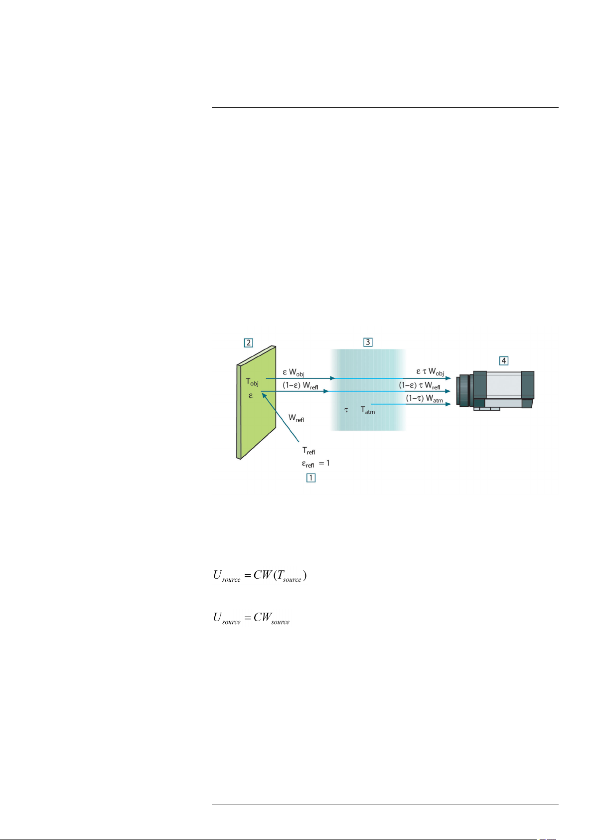
20
The measurement formula
As already mentioned, when viewing an object, the camera receives radiation not only
from the object itself. It also collects radiation from the surroundings reflected via the object surface. Both these radiation contributions become attenuated to some extent by the
atmosphere in the measurement path. To this comes a third radiation contribution from
the atmosphere itself.
This description of the measurement situation, as illustrated in the figure below, is so far
a fairly true description of the real conditions. What has been neglected could for instance be sun light scattering in the atmosphere or stray radiation from intense radiation
sources outside the field of view. Such disturbances are difficult to quantify, however, in
most cases they are fortunately small enough to be neglected. In case they are not negligible, the measurement configuration is likely to be such that the risk for disturbance is
obvious, at least to a trained operator. It is then his responsibility to modify the measurement situation to avoid the disturbance e.g. by changing the viewing direction, shielding
off intense radiation sources etc.
Accepting the description above, we can use the figure below to derive a formula for the
calculation of the object temperature from the calibrated camera output.
Figure 20.1 A schematic representation of the general thermographic measurement situation.1: Surroundings; 2: Object; 3: Atmosphere; 4: Camera
Assume that the received radiation power W from a blackbody source of temperature
T
on short distance generates a camera output signal U
source
the power input (power linear camera). We can then write (Equation 1):
or, with simplified notation:
where C is a constant.
Should the source be a graybody with emittance ε, the received radiation would conse-
quently be εW
We are now ready to write the three collected radiation power terms:
1. Emission from the object = ετW
transmittance of the atmosphere. The object temperature is T
source
.
, where ε is the emittance of the object and τ is the
obj
that is proportional to
source
.
obj
#T559891; r. AD/38469/38469; en-US
53
Page 60

20
The measurement formula
2. Reflected emission from ambient sources = (1 – ε)τW
tance of the object. The ambient sources have the temperature T
It has here been assumed that the temperature T
, where (1 – ε) is the reflec-
refl
.
refl
is the same for all emitting surfa-
refl
ces within the halfsphere seen from a point on the object surface. This is of course
sometimes a simplification of the true situation. It is, however, a necessary simplification in order to derive a workable formula, and T
can – at least theoretically – be giv-
refl
en a value that represents an efficient temperature of a complex surrounding.
Note also that we have assumed that the emittance for the surroundings = 1. This is
correct in accordance with Kirchhoff’s law: All radiation impinging on the surrounding
surfaces will eventually be absorbed by the same surfaces. Thus the emittance = 1.
(Note though that the latest discussion requires the complete sphere around the object to be considered.)
3. Emission from the atmosphere = (1 – τ)τW
mosphere. The temperature of the atmosphere is T
, where (1 – τ) is the emittance of the at-
atm
atm
.
The total received radiation power can now be written (Equation 2):
We multiply each term by the constant C of Equation 1 and replace the CW products by
the corresponding U according to the same equation, and get (Equation 3):
Solve Equation 3 for U
(Equation 4):
obj
This is the general measurement formula used in all the FLIR Systems thermographic
equipment. The voltages of the formula are:
Table 20.1 Voltages
U
obj
U
tot
U
refl
U
atm
Calculated camera output voltage for a blackbody of temperature
i.e. a voltage that can be directly converted into true requested
T
obj
object temperature.
Measured camera output voltage for the actual case.
Theoretical camera output voltage for a blackbody of temperature
T
according to the calibration.
refl
Theoretical camera output voltage for a blackbody of temperature
according to the calibration.
T
atm
The operator has to supply a number of parameter values for the calculation:
• the object emittance ε,
• the relative humidity,
• T
atm
• object distance (D
obj
)
• the (effective) temperature of the object surroundings, or the reflected ambient tem-
perature T
• the temperature of the atmosphere T
refl
, and
atm
This task could sometimes be a heavy burden for the operator since there are normally
no easy ways to find accurate values of emittance and atmospheric transmittance for the
actual case. The two temperatures are normally less of a problem provided the surroundings do not contain large and intense radiation sources.
A natural question in this connection is: How important is it to know the right values of
these parameters? It could though be of interest to get a feeling for this problem already
here by looking into some different measurement cases and compare the relative
#T559891; r. AD/38469/38469; en-US
54
Page 61

20
The measurement formula
magnitudes of the three radiation terms. This will give indications about when it is important to use correct values of which parameters.
The figures below illustrates the relative magnitudes of the three radiation contributions
for three different object temperatures, two emittances, and two spectral ranges: SW and
LW. Remaining parameters have the following fixed values:
• τ = 0.88
• T
= +20°C (+68°F)
refl
• T
= +20°C (+68°F)
atm
It is obvious that measurement of low object temperatures are more critical than measuring high temperatures since the ‘disturbing’ radiation sources are relatively much stronger in the first case. Should also the object emittance be low, the situation would be still
more difficult.
We have finally to answer a question about the importance of being allowed to use the
calibration curve above the highest calibration point, what we call extrapolation. Imagine
that we in a certain case measure U
= 4.5 volts. The highest calibration point for the
tot
camera was in the order of 4.1 volts, a value unknown to the operator. Thus, even if the
object happened to be a blackbody, i.e. U
obj
= U
, we are actually performing extrapola-
tot
tion of the calibration curve when converting 4.5 volts into temperature.
Let us now assume that the object is not black, it has an emittance of 0.75, and the trans-
mittance is 0.92. We also assume that the two second terms of Equation 4 amount to 0.5
volts together. Computation of U
by means of Equation 4 then results in U
obj
obj
= 4.5 /
0.75 / 0.92 – 0.5 = 6.0. This is a rather extreme extrapolation, particularly when considering that the video amplifier might limit the output to 5 volts! Note, though, that the application of the calibration curve is a theoretical procedure where no electronic or other
limitations exist. We trust that if there had been no signal limitations in the camera, and if
it had been calibrated far beyond 5 volts, the resulting curve would have been very much
the same as our real curve extrapolated beyond 4.1 volts, provided the calibration algorithm is based on radiation physics, like the FLIR Systems algorithm. Of course there
must be a limit to such extrapolations.
Figure 20.2 Relative magnitudes of radiation sources under varying measurement conditions (SW camera). 1: Object temperature; 2: Emittance; Obj: Object radiation; Refl: Reflected radiation; Atm: atmosphere radiation. Fixed parameters: τ = 0.88; T
#T559891; r. AD/38469/38469; en-US
= 20°C (+68°F); T
refl
= 20°C (+68°F).
atm
55
Page 62

20
The measurement formula
Figure 20.3 Relative magnitudes of radiation sources under varying measurement conditions (LW cam-
era). 1: Object temperature; 2: Emittance; Obj: Object radiation; Refl: Reflected radiation; Atm: atmosphere radiation. Fixed parameters: τ = 0.88; T
= 20°C (+68°F); T
refl
= 20°C (+68°F).
atm
#T559891; r. AD/38469/38469; en-US
56
Page 63

21
Emissivity tables
This section presents a compilation of emissivity data from the infrared literature and
measurements made by FLIR Systems.
21.1 References
1. Mikaél A. Bramson: Infrared Radiation, A Handbook for Applications, Plenum press,
N.Y.
2. William L. Wolfe, George J. Zissis: The Infrared Handbook, Office of Naval Research,
Department of Navy, Washington, D.C.
3. Madding, R. P.: Thermographic Instruments and systems. Madison, Wisconsin: Uni-
versity of Wisconsin – Extension, Department of Engineering and Applied Science.
4. William L. Wolfe: Handbook of Military Infrared Technology, Office of Naval Research,
Department of Navy, Washington, D.C.
5. Jones, Smith, Probert: External thermography of buildings..., Proc. of the Society of
Photo-Optical Instrumentation Engineers, vol.110, Industrial and Civil Applications of
Infrared Technology, June 1977 London.
6. Paljak, Pettersson: Thermography of Buildings, Swedish Building Research Institute,
Stockholm 1972.
7. Vlcek, J: Determination of emissivity with imaging radiometers and some emissivities
at λ = 5 µm. Photogrammetric Engineering and Remote Sensing.
8. Kern: Evaluation of infrared emission of clouds and ground as measured by weather
satellites, Defence Documentation Center, AD 617 417.
9. Öhman, Claes: Emittansmätningar med AGEMA E-Box. Teknisk rapport, AGEMA
1999. (Emittance measurements using AGEMA E-Box. Technical report, AGEMA
1999.)
10. Matteï, S., Tang-Kwor, E: Emissivity measurements for Nextel Velvet coating 811-21
between –36°C AND 82°C.
11. Lohrengel & Todtenhaupt (1996)
12. ITC Technical publication 32.
13. ITC Technical publication 29.
14. Schuster, Norbert and Kolobrodov, Valentin G. Infrarotthermographie. Berlin: Wiley-
VCH, 2000.
Note The emissivity values in the table below are recorded using a shortwave (SW)
camera. The values should be regarded as recommendations only and used with
caution.
21.2 Tables
Table 21.1 T: Total spectrum; SW: 2–5 µm; LW: 8–14 µm, LLW: 6.5–20 µm; 1: Material; 2: Specification;
3:Temperature in °C; 4: Spectrum; 5: Emissivity: 6:Reference
1 2 3 4 5 6
3M type 35 Vinyl electrical
3M type 88 Black vinyl electri-
3M type 88 Black vinyl electri-
3M type Super 33
+
Aluminum anodized sheet 100 T 0.55 2
Aluminum anodized, black,
Aluminum anodized, black,
Aluminum anodized, light
#T559891; r. AD/38469/38469; en-US
tape (several
colors)
cal tape
cal tape
Black vinyl electrical tape
dull
dull
gray, dull
< 80 LW ≈ 0.96 13
< 105 LW ≈ 0.96 13
< 105 MW < 0.96 13
< 80 LW ≈ 0.96 13
70
70 LW 0.95 9
70
SW
SW
0.67 9
0.61 9
57
Page 64

Emissivity tables21
Table 21.1 T: Total spectrum; SW: 2–5 µm; LW: 8–14 µm, LLW: 6.5–20 µm; 1: Material; 2: Specification;
3:Temperature in °C; 4: Spectrum; 5: Emissivity: 6:Reference (continued)
1 2 3 4 5 6
Aluminum anodized, light
gray, dull
Aluminum as received, plate 100 T 0.09 4
Aluminum as received,
sheet
Aluminum cast, blast
cleaned
Aluminum cast, blast
cleaned
Aluminum dipped in HNO
plate
Aluminum foil
Aluminum foil
Aluminum oxidized, strongly 50–500 T 0.2–0.3 1
Aluminum polished 50–100 T 0.04–0.06 1
Aluminum polished plate 100 T 0.05 4
Aluminum polished, sheet 100 T 0.05 2
Aluminum rough surface
Aluminum roughened 27 10 µm 0.18 3
Aluminum roughened 27 3 µm 0.28 3
Aluminum sheet, 4 samples
differently
scratched
Aluminum sheet, 4 samples
differently
scratched
Aluminum
vacuum
deposited
Aluminum weathered,
heavily
Aluminum bronze 20 T 0.60 1
Aluminum
powder T 0.28 1
hydroxide
Aluminum oxide activated, powder T 0.46 1
Aluminum oxide pure, powder
(alumina)
Asbestos board 20 T 0.96 1
Asbestos fabric T 0.78 1
Asbestos floor tile
Asbestos
paper 40–400 T 0.93–0.95 1
Asbestos powder T 0.40–0.60 1
Asbestos slate 20 T 0.96 1
Asphalt paving 4 LLW 0.967 8
Brass dull, tarnished 20–350 T 0.22 1
Brass oxidized 100 T 0.61 2
Brass oxidized 70
Brass oxidized 70 LW 0.03–0.07 9
Brass oxidized at 600°C
70 LW 0.97 9
100 T 0.09 2
70
SW
0.47 9
70 LW 0.46 9
100 T 0.05 4
,
3
27 10 µm 0.04 3
27 3 µm 0.09 3
20–50 T 0.06–0.07 1
70
SW
0.05–0.08 9
70 LW 0.03–0.06 9
20 T 0.04 2
17
SW
0.83–0.94 5
T 0.16 1
35
SW
SW
0.94 7
0.04–0.09 9
200–600 T 0.59–0.61 1
#T559891; r. AD/38469/38469; en-US
58
Page 65

Emissivity tables21
Table 21.1 T: Total spectrum; SW: 2–5 µm; LW: 8–14 µm, LLW: 6.5–20 µm; 1: Material; 2: Specification;
3:Temperature in °C; 4: Spectrum; 5: Emissivity: 6:Reference (continued)
1 2 3 4 5 6
Brass polished 200 T 0.03 1
Brass polished, highly 100 T 0.03 2
Brass rubbed with 80-
grit emery
Brass sheet, rolled 20 T 0.06 1
Brass sheet, worked
with emery
Brick alumina 17
Brick
common 17
Brick Dinas silica,
glazed, rough
Brick Dinas silica,
refractory
Brick Dinas silica, un-
glazed, rough
Brick firebrick
Brick fireclay
Brick fireclay
Brick fireclay
Brick
Brick
masonry 35
masonry,
plastered
Brick red, common 20 T 0.93 2
Brick red, rough 20 T 0.88–0.93 1
Brick refractory,
corundum
Brick refractory,
magnesite
Brick refractory,
strongly radiating
Brick refractory, weakly
radiating
Brick silica, 95% SiO
Brick sillimanite, 33%
SiO
, 64% Al2O
2
Brick waterproof
Bronze phosphor bronze 70
Bronze phosphor bronze 70 LW 0.06 9
Bronze polished 50 T 0.1 1
Bronze porous, rough 50–150 T 0.55 1
Bronze powder T 0.76–0.80 1
Carbon
Carbon
candle soot 20 T 0.95 2
charcoal powder T 0.96 1
Carbon graphite powder T 0.97 1
Carbon graphite, filed
surface
Carbon lampblack 20–400 T 0.95–0.97 1
20 T 0.20 2
20 T 0.2 1
SW
SW
0.68 5
0.86–0.81 5
1100 T 0.85 1
1000 T 0.66 1
1000 T 0.80 1
17
SW
0.68 5
1000 T 0.75 1
1200 T 0.59 1
20 T 0.85 1
SW
0.94 7
20 T 0.94 1
1000 T 0.46 1
1000–1300 T 0.38 1
500–1000 T 0.8–0.9 1
500–1000 T 0.65–0.75 1
1230 T 0.66 1
2
1500 T 0.29 1
3
17
SW
SW
0.87 5
0.08 9
20 T 0.98 2
#T559891; r. AD/38469/38469; en-US
59
Page 66

Emissivity tables21
Table 21.1 T: Total spectrum; SW: 2–5 µm; LW: 8–14 µm, LLW: 6.5–20 µm; 1: Material; 2: Specification;
3:Temperature in °C; 4: Spectrum; 5: Emissivity: 6:Reference (continued)
1 2 3 4 5 6
Chipboard
Chromium
Chromium polished 500–1000 T 0.28–0.38 1
Clay fired
Cloth
Concrete
Concrete dry 36 SW
Concrete rough 17 SW
Concrete
Copper
Copper electrolytic, care-
Copper
Copper
Copper
Copper
Copper
Copper
Copper
Copper
Copper
Copper polished,
Copper pure, carefully
Copper
Copper dioxide
Copper oxide
Ebonite T 0.89 1
Emery
Enamel 20 T 0.9 1
Enamel lacquer 20 T 0.85–0.95 1
Fiber board hard, untreated 20
Fiber board masonite 70
Fiber board masonite 70 LW 0.88 9
Fiber board particle board 70
Fiber board particle board 70 LW 0.89 9
Fiber board porous, untreated 20
Glass pane (float
glass)
Gold polished 130 T 0.018 1
untreated 20
polished 50 T 0.10 1
70 T 0.91 1
black 20 T 0.98 1
20 T 0.92 2
walkway
commercial,
burnished
fully polished
electrolytic,
polished
molten 1100–1300 T 0.13–0.15 1
oxidized 50 T 0.6–0.7 1
oxidized to
blackness
oxidized, black 27 T 0.78 4
oxidized, heavily 20 T 0.78 2
polished 50–100 T 0.02 1
polished 100 T 0.03 2
polished,
commercial
mechanical
prepared surface
scraped 27 T 0.07 4
powder T 0.84 1
red, powder T 0.70 1
coarse 80 T 0.85 1
non-coated 20 LW 0.97 14
5
20 T 0.07 1
80 T 0.018 1
–34 T 0.006 4
27 T 0.03 4
22 T 0.015 4
22 T 0.008 4
SW
LLW 0.974 8
T 0.88 1
SW
SW
SW
SW
0.90 6
0.95 7
0.97 5
0.85 6
0.75 9
0.77 9
0.85 6
#T559891; r. AD/38469/38469; en-US
60
Page 67

Emissivity tables21
Table 21.1 T: Total spectrum; SW: 2–5 µm; LW: 8–14 µm, LLW: 6.5–20 µm; 1: Material; 2: Specification;
3:Temperature in °C; 4: Spectrum; 5: Emissivity: 6:Reference (continued)
1 2 3 4 5 6
Gold polished, carefully
Gold
Granite
Granite rough 21 LLW 0.879 8
Granite rough, 4 different
Granite rough, 4 different
Gypsum
Ice: See Water
Iron and steel cold rolled 70
Iron and steel cold rolled 70 LW 0.09 9
Iron and steel covered with red
Iron and steel electrolytic 100 T 0.05 4
Iron and steel electrolytic 22 T 0.05 4
Iron and steel electrolytic 260 T 0.07 4
Iron and steel electrolytic, care-
Iron and steel freshly worked
Iron and steel ground sheet 950–1100 T 0.55–0.61 1
Iron and steel heavily rusted
Iron and steel hot rolled 130 T 0.60 1
Iron and steel hot rolled 20 T 0.77 1
Iron and steel oxidized 100 T 0.74 4
Iron and steel oxidized 100 T 0.74 1
Iron and steel oxidized 1227 T 0.89 4
Iron and steel oxidized 125–525 T 0.78–0.82 1
Iron and steel oxidized 200 T 0.79 2
Iron and steel oxidized 200–600 T 0.80 1
Iron and steel oxidized strongly 50 T 0.88 1
Iron and steel oxidized strongly 500 T 0.98 1
Iron and steel polished 100 T 0.07 2
Iron and steel polished 400–1000 T 0.14–0.38 1
Iron and steel polished sheet 750–1050 T 0.52–0.56 1
Iron and steel rolled sheet 50 T 0.56 1
Iron and steel rolled, freshly
Iron and steel rough, plane
Iron and steel rusted red, sheet 22 T 0.69 4
Iron and steel rusted, heavily 17
Iron and steel rusty, red 20 T 0.69 1
Iron and steel shiny oxide layer,
polished, highly 100 T 0.02 2
polished 20 LLW 0.849 8
samples
samples
rust
fully polished
with emery
sheet
surface
sheet,
200–600 T 0.02–0.03 1
70
70 LW 0.77–0.87 9
20 T 0.8–0.9 1
20 T 0.61–0.85 1
175–225 T 0.05–0.06 1
20 T 0.24 1
20 T 0.69 2
20 T 0.24 1
50 T 0.95–0.98 1
20 T 0.82 1
SW
SW
SW
0.95–0.97 9
0.20 9
0.96 5
#T559891; r. AD/38469/38469; en-US
61
Page 68

Emissivity tables21
Table 21.1 T: Total spectrum; SW: 2–5 µm; LW: 8–14 µm, LLW: 6.5–20 µm; 1: Material; 2: Specification;
3:Temperature in °C; 4: Spectrum; 5: Emissivity: 6:Reference (continued)
1 2 3 4 5 6
Iron and steel shiny, etched 150 T 0.16 1
Iron and steel wrought, carefully
Iron galvanized heavily oxidized 70
Iron galvanized heavily oxidized 70 LW 0.85 9
Iron galvanized sheet 92 T 0.07 4
Iron galvanized sheet, burnished 30 T 0.23 1
Iron galvanized sheet, oxidized 20 T 0.28 1
Iron tinned sheet 24 T 0.064 4
Iron, cast casting 50 T 0.81 1
Iron, cast ingots 1000 T 0.95 1
Iron, cast liquid 1300 T 0.28 1
Iron, cast machined 800–1000 T 0.60–0.70 1
Iron, cast oxidized 100 T 0.64 2
Iron, cast oxidized 260 T 0.66 4
Iron, cast oxidized 38 T 0.63 4
Iron, cast oxidized 538 T 0.76 4
Iron, cast oxidized at 600°C
Iron, cast polished 200 T 0.21 1
Iron, cast polished 38 T 0.21 4
Iron, cast polished 40 T 0.21 2
Iron, cast unworked 900–1100 T 0.87–0.95 1
Krylon Ultra-flat
black 1602
Krylon Ultra-flat
black 1602
Lacquer 3 colors sprayed
Lacquer 3 colors sprayed
Lacquer Aluminum on
Lacquer bakelite 80 T 0.83 1
Lacquer black, dull 40–100 T 0.96–0.98 1
Lacquer black, matte 100 T 0.97 2
Lacquer black, shiny,
Lacquer heat–resistant 100 T 0.92 1
Lacquer white 100 T 0.92 2
Lacquer white 40–100 T 0.8–0.95 1
Lead oxidized at 200°C
Lead oxidized, gray 20 T 0.28 1
Lead oxidized, gray 22 T 0.28 4
Lead shiny 250 T 0.08 1
polished
Flat black Room tempera-
Flat black Room tempera-
on Aluminum
on Aluminum
rough surface
sprayed on iron
40–250 T 0.28 1
SW
200–600 T 0.64–0.78 1
ture up to 175
ture up to 175
70
70 LW 0.92–0.94 9
20 T 0.4 1
20 T 0.87 1
200 T 0.63 1
LW ≈ 0.96 12
MW ≈ 0.97 12
SW
0.64 9
0.50–0.53 9
#T559891; r. AD/38469/38469; en-US
62
Page 69

Emissivity tables21
Table 21.1 T: Total spectrum; SW: 2–5 µm; LW: 8–14 µm, LLW: 6.5–20 µm; 1: Material; 2: Specification;
3:Temperature in °C; 4: Spectrum; 5: Emissivity: 6:Reference (continued)
1 2 3 4 5 6
Lead unoxidized,
Lead red 100 T 0.93 4
Lead red, powder 100 T 0.93 1
Leather tanned T 0.75–0.80 1
Lime T 0.3–0.4 1
Magnesium 22 T 0.07 4
Magnesium 260 T 0.13 4
Magnesium 538 T 0.18 4
Magnesium polished 20 T 0.07 2
Magnesium
powder
Molybdenum 1500–2200 T 0.19–0.26 1
Molybdenum 600–1000 T 0.08–0.13 1
Molybdenum filament
Mortar 17
Mortar dry 36
Nextel Velvet
811-21 Black
Nichrome rolled 700 T 0.25 1
Nichrome sandblasted 700 T 0.70 1
Nichrome wire, clean 50 T 0.65 1
Nichrome wire, clean 500–1000 T 0.71–0.79 1
Nichrome wire, oxidized 50–500 T 0.95–0.98 1
Nickel bright matte 122 T 0.041 4
Nickel commercially
Nickel commercially
Nickel electrolytic 22 T 0.04 4
Nickel electrolytic 260 T 0.07 4
Nickel electrolytic 38 T 0.06 4
Nickel electrolytic 538 T 0.10 4
Nickel electroplated on
Nickel electroplated on
Nickel electroplated on
Nickel electroplated,
Nickel oxidized 1227 T 0.85 4
Nickel oxidized 200 T 0.37 2
Nickel oxidized 227 T 0.37 4
Nickel oxidized at 600°C
Nickel polished 122 T 0.045 4
polished
Flat black –60–150 LW > 0.97 10 and
pure, polished
pure, polished
iron, polished
iron, unpolished
iron, unpolished
polished
100 T 0.05 4
T 0.86 1
700–2500 T 0.1–0.3 1
SW
SW
100 T 0.045 1
200–400 T 0.07–0.09 1
22 T 0.045 4
20 T 0.11–0.40 1
22 T 0.11 4
20 T 0.05 2
200–600 T 0.37–0.48 1
0.87 5
0.94 7
11
#T559891; r. AD/38469/38469; en-US
63
Page 70

Emissivity tables21
Table 21.1 T: Total spectrum; SW: 2–5 µm; LW: 8–14 µm, LLW: 6.5–20 µm; 1: Material; 2: Specification;
3:Temperature in °C; 4: Spectrum; 5: Emissivity: 6:Reference (continued)
1 2 3 4 5 6
Nickel wire 200–1000 T 0.1–0.2 1
Nickel oxide 1000–1250 T 0.75–0.86 1
Nickel oxide 500–650 T 0.52–0.59 1
Oil, lubricating 0.025 mm film
Oil, lubricating 0.050 mm film
Oil, lubricating 0.125 mm film
Oil, lubricating film on Ni base:
Oil, lubricating
Paint 8 different colors
Paint 8 different colors
Paint Aluminum, vari-
Paint cadmium yellow T 0.28–0.33 1
Paint chrome green T 0.65–0.70 1
Paint cobalt blue T 0.7–0.8 1
Paint oil 17
Paint oil based, aver-
Paint oil, black flat
Paint oil, black gloss 20
Paint oil, gray flat
Paint oil, gray gloss 20
Paint oil, various colors 100 T 0.92–0.96 1
Paint plastic, black 20
Paint plastic, white 20
Paper 4 different colors
Paper 4 different colors
Paper black T 0.90 1
Paper black, dull T 0.94 1
Paper black, dull 70
Paper black, dull 70 LW 0.89 9
Paper blue, dark T 0.84 1
Paper coated with black
Paper
Paper red T 0.76 1
Paper white 20 T 0.7–0.9 1
Paper white bond 20 T 0.93 2
Paper white, 3 different
Paper white, 3 different
Ni base only
thick coating 20 T 0.82 2
and qualities
and qualities
ous ages
age of 16 colors
lacquer
green
glosses
glosses
20 T 0.27 2
20 T 0.46 2
20 T 0.72 2
20 T 0.05 2
70
70 LW 0.92–0.94 9
50–100 T 0.27–0.67 1
100 T 0.94 2
20
20
70
70 LW 0.92–0.94 9
70
70 LW 0.88–0.90 9
SW
SW
SW
SW
SW
SW
SW
SW
SW
SW
T 0.93 1
T 0.85 1
SW
0.88–0.96 9
0.87 5
0.94 6
0.92 6
0.97 6
0.96 6
0.95 6
0.84 6
0.68–0.74 9
0.86 9
0.76–0.78 9
#T559891; r. AD/38469/38469; en-US
64
Page 71

Emissivity tables21
Table 21.1 T: Total spectrum; SW: 2–5 µm; LW: 8–14 µm, LLW: 6.5–20 µm; 1: Material; 2: Specification;
3:Temperature in °C; 4: Spectrum; 5: Emissivity: 6:Reference (continued)
1 2 3 4 5 6
Paper yellow T 0.72 1
Plaster 17
Plaster plasterboard,
Plaster rough coat 20 T 0.91 2
Plastic glass fibre lami-
Plastic glass fibre lami-
Plastic polyurethane iso-
Plastic polyurethane iso-
Plastic PVC, plastic floor,
Plastic PVC, plastic floor,
Platinum 100 T 0.05 4
Platinum 1000–1500 T 0.14–0.18 1
Platinum 1094 T 0.18 4
Platinum 17 T 0.016 4
Platinum 22 T 0.03 4
Platinum 260 T 0.06 4
Platinum 538 T 0.10 4
Platinum pure, polished 200–600 T 0.05–0.10 1
Platinum ribbon 900–1100 T 0.12–0.17 1
Platinum wire 1400 T 0.18 1
Platinum wire 500–1000 T 0.10–0.16 1
Platinum wire 50–200 T 0.06–0.07 1
Porcelain glazed 20 T 0.92 1
Porcelain white, shiny T 0.70–0.75 1
Rubber hard 20 T 0.95 1
Rubber soft, gray, rough
Sand
Sand
Sandstone
Sandstone rough 19 LLW 0.935 8
Silver
Silver pure, polished 200–600 T 0.02–0.03 1
Skin
Slag
Slag boiler 1400–1800 T 0.69–0.67 1
Slag boiler 200–500 T 0.89–0.78 1
Slag
Snow: See Water
untreated
nate (printed circ.
board)
nate (printed circ.
board)
lation board
lation board
dull, structured
dull, structured
polished 19 LLW 0.909 8
polished 100 T 0.03 2
human 32 T 0.98 2
boiler 0–100 T 0.97–0.93 1
boiler 600–1200 T 0.76–0.70 1
20
70
70 LW 0.91 9
70 LW 0.55 9
70
70
70 LW 0.93 9
20 T 0.95 1
20 T 0.90 2
SW
SW
SW
SW
SW
T 0.60 1
0.86 5
0.90 6
0.94 9
0.29 9
0.94 9
#T559891; r. AD/38469/38469; en-US
65
Page 72

Emissivity tables21
Table 21.1 T: Total spectrum; SW: 2–5 µm; LW: 8–14 µm, LLW: 6.5–20 µm; 1: Material; 2: Specification;
3:Temperature in °C; 4: Spectrum; 5: Emissivity: 6:Reference (continued)
1 2 3 4 5 6
Soil
Soil saturated with
Stainless steel
Stainless steel
Stainless steel
Stainless steel
Stainless steel sheet, polished 70 LW 0.14 9
Stainless steel
Stainless steel sheet, untreated,
Stainless steel type 18-8, buffed
Stainless steel
Stucco
Styrofoam
Tar T 0.79–0.84 1
Tar
Tile glazed 17
Tin burnished 20–50 T 0.04–0.06 1
Tin tin–plated sheet
Titanium
Titanium oxidized at 540°C
Titanium
Titanium polished 1000 T 0.36 1
Titanium polished 200 T 0.15 1
Titanium polished 500 T 0.20 1
Tungsten 1500–2200 T 0.24–0.31 1
Tungsten 200 T 0.05 1
Tungsten 600–1000 T 0.1–0.16 1
Tungsten filament
Varnish flat
Varnish on oak parquet
Varnish on oak parquet
Wallpaper slight pattern,
Wallpaper slight pattern, red 20
Water distilled 20 T 0.96 2
Water frost crystals
Water ice, covered with
dry 20 T 0.92 2
water
alloy, 8% Ni, 18%
Cr
rolled 700 T 0.45 1
sandblasted 700 T 0.70 1
sheet, polished 70
sheet, untreated,
somewhat
scratched
somewhat
scratched
type 18-8, oxidized at 800°C
rough, lime 10–90 T 0.91 1
insulation 37
paper 20 T 0.91–0.93 1
iron
oxidized at 540°C
oxidized at 540°C
floor
floor
light gray
heavy frost
20 T 0.95 2
500 T 0.35 1
SW
70
70 LW 0.28 9
20 T 0.16 2
60 T 0.85 2
100 T 0.07 2
1000 T 0.60 1
200 T 0.40 1
500 T 0.50 1
3300 T 0.39 1
20
70
70 LW 0.90–0.93 9
20
–10 T 0.98 2
0 T 0.98 1
SW
SW
SW
SW
SW
SW
SW
0.18 9
0.30 9
0.60 7
0.94 5
0.93 6
0.90 9
0.85 6
0.90 6
#T559891; r. AD/38469/38469; en-US
66
Page 73

Emissivity tables21
Table 21.1 T: Total spectrum; SW: 2–5 µm; LW: 8–14 µm, LLW: 6.5–20 µm; 1: Material; 2: Specification;
3:Temperature in °C; 4: Spectrum; 5: Emissivity: 6:Reference (continued)
1 2 3 4 5 6
Water ice, smooth 0 T 0.97 1
Water ice, smooth –10 T 0.96 2
Water layer >0.1 mm
Water
Water
Wood 17
Wood 19 LLW 0.962 8
Wood ground T 0.5–0.7 1
Wood pine, 4 different
Wood pine, 4 different
Wood planed 20 T 0.8–0.9 1
Wood planed oak 20 T 0.90 2
Wood planed oak 70
Wood planed oak 70 LW 0.88 9
Wood plywood, smooth,
Wood plywood,
Wood white, damp 20 T 0.7–0.8 1
Zinc
Zinc oxidized surface
Zinc polished 200–300 T 0.04–0.05 1
Zinc sheet 50 T 0.20 1
thick
snow
snow –10 T 0.85 2
samples
samples
dry
untreated
oxidized at 400°C
0–100 T 0.95–0.98 1
T 0.8 1
SW
70
70 LW 0.81–0.89 9
36
20
400 T 0.11 1
1000–1200 T 0.50–0.60 1
SW
SW
SW
SW
0.98 5
0.67–0.75 9
0.77 9
0.82 7
0.83 6
#T559891; r. AD/38469/38469; en-US
67
Page 74

A
OEM manual (German)
This section contains the original manual from the manufacturer of the enclosure.
#T559891; r. AD/38469/38469; en-US
68
Page 75

Betriebsanleitung
IRCamSafeEX-AXC Ex-d Gehäuse für
Infrarotkameras
AT – Automation Technology GmbH
Datum: 01.04.2016
Revision: 1.
3
© AT – Automation Technology GmbH 2016
Page 76

Betriebsanleitung IRCamSafeEX-AXC
Ex-d Gehäuse für Infrarotkameras 1 AT-Automation Technology GmbH
1 Inhaltsverzeichnis
2 Allgemeine Angaben........................................................................................................................ 2
2.1 Hersteller ................................................................................................................................. 2
2.2 Einleitung ................................................................................................................................. 2
2.3 Kennzeichnung ........................................................................................................................ 3
3 Allgemeine Sicherheitshinweise ...................................................................................................... 4
4 Verwendung und Vorgesehener Einsatzbereich ............................................................................. 5
4.1 Zulässige Einbauten ................................................................................................................. 5
4.2 Zulässige Kabeleinführungen und Steckverbinder .................................................................. 6
4.3 Ausführung mit vorkonfektionierten Anschlusskabeln ........................................................... 6
5 Normenkonformität ........................................................................................................................ 7
6 Technische Daten ............................................................................................................................ 8
7 Transport, Lagerung und Entsorgung ........................................................................................... 10
8 Montage und Demontage ............................................................................................................. 10
9 Installation ..................................................................................................................................... 11
9.1 Installation der Anschlussleitungen ...................................................................................... 12
9.1.1 Hinteren Gehäusedeckel abschrauben ......................................................................... 12
9.1.2 Auflegen der Anschlussleitungen .................................................................................. 12
9.1.3 Hinteren Gehäusedeckel schließen ............................................................................... 13
9.1.4 Erdungsanschluss auflegen ........................................................................................... 13
10 Inbetriebnahme ......................................................................................................................... 14
11 Wartung ..................................................................................................................................... 15
11.1 Regelmäßige Wartungsarbeiten ............................................................................................ 15
11.2 Reinigung ............................................................................................................................... 16
12 Zubehör und Ersatzteile ............................................................................................................ 16
13 EG-Baumusterprüfbescheinigung ............................................................................................. 17
14 EG-Konformitätserklärung ......................................................................................................... 21
Page 77

Betriebsanleitung IRCamSafeEX-AXC
Ex-d Gehäuse für Infrarotkameras 2 AT-Automation Technology GmbH
2 Allgemeine Angaben
2.1 Hersteller
AT-Automation Technology GmbH
Hermann-Bössow-Str. 6-8
23843 Bad Oldesloe
Germany
Telefon: +49 4531 88011-0
Telefax: +49 34531 88011-20
Internet: www.AutomationTechnology.de
2.2 Einleitung
Bei den Kameragehäusen der Serie IRCamSafeEX-AXB/C handelt es sich um Schutzgehäuse für
Infrarotkameras. Die Gehäuse sind für den Einsatz von Infrarotkameras der Serie FLIR
A3XX/SC3XX und A615/SC6XX, sowie Flir G300A und AT IRS und Xenics Serval in
explosionsgefährdeten Bereichen konzipiert. Die Variante–AXC ist zudem für den Einsatz in
staubexplosionsgefährlicher Atmosphäre zugelassen.
Die Schutzgehäuse erfüllen die aktuellen EX-Schutz Normen und sind als komplette Einheit mit
allen Einbauten zertifiziert. Eine zusätzliche Zertifizierung nach Einbau der vorgesehenen
Kameras ist somit nicht mehr notwendig.
Page 78

Betriebsanleitung IRCamSafeEX-AXC
Ex-d Gehäuse für Infrarotkameras 3 AT-Automation Technology GmbH
2.3 Kennzeichnung
Gehäusevariante 24V DC:
AT – Automation Technology GmbH
Hermann-Bössow-Straße 6 – 8 • 23843 Bad Oldesloe • Germany
Phone: +49 4531 88011-0 • www.AutomationTechnology.de
Model: IRCamSafeEX-AXC
Serial No.:
71000260
Year: 2016
Power: 24VDC, 60W
T
-40°C - +40°C / 60°C
Certificate:
ZELM 12 ATEX 0485
X 0820
IP67
WARNUNG / WARNING / ADVERTENCIA / ATTENTION !
NICHT UNTER SPANNUNG ÖFFNEN / DE-ENERGIZE BEFORE OPENING
DESENERGIZAR ANTES DE ABRIR / NE PAS OUVIRIR SOUS TENSION
NACH DEM ABSCHALTEN 10 MINUTEN WARTEN VOR DEM ÖFFNEN.
Gehäusevariante 230V AC:
AT –
Automation Technology GmbH
Hermann-Bössow-Straße 6 –
8 • 23843 Bad Oldesloe • Germany
Phone: +49 4531 88011-0 • www.AutomationTechnology.de
Model: IRCamSafeEX-AXC
Serial No.: 71000260 Year: 2016
Power: 230VAC, 60W T
-40°C - +40°C / 60°C
Certificate:
ZELM 12 ATEX 0485 X
0820
IP67
WARNUNG / WARNING / ADVERTENCIA / ATTENTION !
NICHT UNTER SPANNUNG ÖFFNEN / DE-ENERGIZE BEFORE OPENING
DESENERGIZAR ANTES DE ABRIR / NE PAS OUVIRIR SOUS TENSION
NACH DEM ABSCHALTEN 10 MINUTEN WARTEN VOR DEM ÖFFNEN.
II 2G Ex db IIC T6 / T5
II 2D Ex tb IIIC T85° / T100°
II 2G Ex d
b II
C T6 / T
5
II 2D
Ex tb IIIC T
85° / T100°
Page 79

Betriebsanleitung IRCamSafeEX-AXC
Ex-d Gehäuse für Infrarotkameras 4 AT-Automation Technology GmbH
3 Allgemeine Sicherheitshinweise
Die Betriebsanleitung enthält grundlegende Sicherheitshinweise, die bei Aufstellung, Betrieb
und Wartung zu beachten sind. Nichtbeachtung hat eine Gefährdung für Personen, Anlage und
Umwelt zur Folge.
Gefahr durch unbefugte Arbeiten am Gerät!
Montage, Installation, Inbetriebnahme, Betrieb und Wartung dürfen ausschließlich von
dazu befugtem und entsprechend geschultem Personal durchgeführt werden.
Vor Montage/Inbetriebnahme:
• Betriebsanleitung lesen.
• Montage- und Betriebspersonal ausreichend schulen.
• Sicherstellen, dass der Inhalt der Betriebsanleitung vom zuständigen Personal voll
verstanden wird.
• Es gelten die nationalen Montage- und Errichtungsvorschriften (z.B. IEC/EN 60079-14).
Bei Unklarheiten:
Mit dem Hersteller Kontakt aufnehmen.
Bei Betrieb der Geräte:
• Betriebsanleitung am Einsatzort verfügbar halten.
• Sicherheitshinweise beachten.
• Nationale Sicherheits- und Unfallverhütungsvorschriften beachten.
• Gerät nur entsprechend der Leistungsdaten betreiben.
• Wartungsarbeiten bzw. Reparaturen, die nicht in der Betriebsanleitung beschrieben
sind, dürfen nicht ohne vorherige Abstimmung mit dem Hersteller durchgeführt werden.
• Beschädigungen können den Explosionsschutz aufheben.
• Umbauten und Veränderungen am Gerät, die den Explosionsschutz beeinträchtigen, sind
nicht gestattet.
• Gerät nur in unbeschädigtem, trockenem und sauberem Zustand einbauen und
betreiben.
Page 80

Betriebsanleitung IRCamSafeEX-AXC
Ex-d Gehäuse für Infrarotkameras 5 AT-Automation Technology GmbH
4 Verwendung und Vorgesehener Einsatzbereich
Die Schutzgehäuse sind für den Einsatz von Infrarotkameras in explosionsgefährdeten
Bereichen der Zone 1 und 2, sowie 21 und 22 zugelassen.
Gerät nur bestimmungsgemäß einsetzen!
Sonst erlischt Herstellerhaftung und Gewährleistung.
Gerät ausschließlich entsprechend den in dieser Betriebsanleitung festgelegten Betriebsbedingungen verwenden.
Das Gerät darf in explosionsgefährdeten Bereichen nur gemäß dieser Betriebsanleitung betrieben
werden.
4.1 Zulässige Einbauten
Folgende Kamera und Optikkombinationen können eingesetzt werden.
Kamera
Optik
Variante
- AXC
Flir
A3XX
,
SC3XX,
A3XXsc
ohne Zusatzoptik
X
45° Zusatzoptik, f‘ = 10mm
X
15° Zusatzoptik, f‘ = 30mm
X
6°
Zusatzoptik, f‘ = 76mm
X
90° Zusatzoptik, f‘ = 4mm
X
Flir
A615
,
SC6XX,
A6XXsc
15° Optik, f‘ = 41
,
3mm
X
25° Optik, f‘ = 24
,
6mm
X
45° Optik, f‘ = 13
,
1mm
X
AT
IRS-X-GigE NFOV Optiken
X
IRS-X-GigE
Xenics Serval-X-GigE
Optik, f‘ = 11mm
X
Optik, f‘
= 25mm
X
Optik, f‘ =35mm
X
Optik, f‘ = 60mm
X
Optik, f‘ = 100mm
X
Optik, f‘=35
-
105mm
X
AX5 NFOV Optiken
X
Flir
G300A
f‘ = 23mm, F=1
,5
f‘=38mm, F=1,5
X
Installationsarbeiten nur durch Fachpersonal!
Die Montage der Einbauten erfolgt durch den Hersteller oder durch vom Hersteller autorisiertes
Personal.
Page 81
Betriebsanleitung IRCamSafeEX-AXC
Ex-d Gehäuse für Infrarotkameras 6 AT-Automation Technology GmbH
4.2 Zulässige Kabeleinführungen und Steckverbinder
Für den Anschluss der Stromversorgungsleitung und der Datenübertragungsleitung stehen zwei
druckfeste und zünddurchschlagsichere Kabeleinführungen zur Verfügung. Alternativ können
druckfeste und zünddurchschlagsichere Steckverbindersysteme eingesetzt werden. Die
Kabeleinführungen und Steckverbinderbuchsen sind vom Hersteller vormontiert. Optional wird
vom Hersteller das Gehäuse zusätzlich mit bereits angeschlossenen Anschlusskabeln geliefert.
Folgende EX-Kabeleinführungen sind für die Verwendung mit dem Schutzgehäuse geeignet.
Hersteller
Bezeichnung
Größe
Manteldurchmesser
A1 mm
Max. Anzahl
Einzeladern
Stahl
8163/2
-
20S/16
-
PXSS2K
-
M20 20s/16
3.1–
8.7 15
Stahl
8163/2
-
20S-PXSS2K
-
M20 20s 6.1 –
11.7 15
Stahl
8163/2
-20-
PXSS2K
-
M20 20 6.5 –
14.0 15
Stahl
8163/2
-
20S/16
-
PX2K
-
M20 20s/16
6.1 -
11.5 15
Stahl
8163/2
-
20S-PX2K
-
M20 20s 9.5 –
15.9 15
Stahl
8163/2
-20-
PX2K
-
M20 20 12.5
– 20.9 15
Hummel
EXIOS Barrier 1.606.2000.50
20-1 6 – 12 8
Hummel
EXIOS Barrier 1.606.2000.51
20-2 9 – 16 10
Hummel
EXIOS Barrier 1.606.2000.52
20-3
12.5
– 20.5 15
Folgende EX-Steckverbindersysteme sind für die Verwendung mit dem Schutzgehäuse geeignet.
Hersteller
Beschreibung
Bezeichnung
Stahl
Gerätestecker für Stromversorgungsanschluss
2 polig + PE
8591/16.
-06-
3.00
Stahl
Gerätestecker in Ethernet Ausführung 4 polig
8591/467
-01-
3022
Hawke
Einbaubuchse für
Stromversorgungsanschluss, 4 polig
N-
BR1-M-B-P-X-0-3-X-A
Hawke
Einbaubuchse für Ethernetanschluss, 8 polig
N-
BR1-M-C-P-X-0-8-X-A
Im Zuge von Aktualisierungen kann sich die Kennzeichnung entsprechend den aktuellen
Normanforderungen ändern.
Installationsarbeiten nur durch Fachpersonal!
Die Montage der Kabeleinführungen und der gehäuseseitigen Steckverbinder erfolgt durch den
Hersteller oder durch vom Hersteller autorisiertes Personal.
4.3 Ausführung mit vorkonfektionierten Anschlusskabeln
Anschluss 1 (Datenverbindung) ist mit einem LWL-Anschlusskabel mit folgenden Eigenschaften
ausgestattet.
• Vieradriges LWL Breakoutkabel für den Außeneinsatz, AT-V(ZN)Y(ZN)Y 4G50/125 OM2 oder
62.5/125 OM1 (z.B. Helukabel 803348 mit Manteldurchmesser 8,5mm)
• 4x LC Stecker auf der Gehäuseinnenseite vorkonfektioniert, Einzelader Innenlänge 450mm
Page 82

Betriebsanleitung IRCamSafeEX-AXC
Ex-d Gehäuse für Infrarotkameras 7 AT-Automation Technology GmbH
• Zweite Anschlussseite ist nicht-konfektioniert und zum Spleißen geeignet
• Typische Länge 5m
Anschluss 2 (Stromversorgung) ist mit einem 3 adrigen Kupfer-Kabel (z.B. Helukabel 37264) mit
folgenden Eigenschaften ausgestattet.
• Manteldurchmesser: 9.8mm
• Aderquerschnitt: 3 x 1,5mm
2
feindrähtig
• Typische Länge 5m, optional mit Stecker Stahl 8570/12-306 konfektioniert
Kundenspezifische Längen und Konfektionierungen der freien Enden sind auf Anfrage möglich.
5 Normenkonformität
Die Schutzgehäuse entsprechen den folgenden Normen und Richtlinien:
• Richtlinie 94/9/EG
• EN 60079-0:2014; „Explosionsfähige Atmosphäre - Teil 0: Geräte - Allgemeine
Anforderungen“
• EN 60079-1:2014; „Explosionsfähige Atmosphäre - Teil 1: Geräteschutz durch druckfeste
Kapselung „d““
• EN 600079-31:2014; „Explosionsfähige Atmosphäre - Teil 31: Geräte-Staubexplosionsschutz
durch Gehäuse "t"“
Für den Einsatz des Schutzgehäuses sind u.a. folgende Normen zu beachten:
• EN 60079-14:2014; „Explosionsfähige Atmosphäre - Teil 14: Projektierung, Auswahl und
Errichtung elektrischer Anlagen“
• EN 60079-17:2014; „Explosionsfähige Atmosphäre - Teil 17: Prüfung und Instandhaltung
elektrischer Anlagen“
• EN 60079-28:2007; „Explosionsfähige Atmosphäre - Teil 28: Schutz von Einrichtungen und
Übertragungssystemen, die mit optischer Strahlung arbeiten“
Page 83

Betriebsanleitung IRCamSafeEX-AXC
Ex-d Gehäuse für Infrarotkameras 8 AT-Automation Technology GmbH
6 Technische Daten
Allgemeine technische Daten:
• Normal-Betriebsumgebungstemperaturbereich T
a
: -40°C … +60°C
• Schutzart: IP67
• Gewicht: 6,7 kg (ohne Kamera und Optik)
• Leervolumen: 5,06l
• Außenmaße (ohne Sonnendach und Anschlüsse): D=170mm, L=408mm
• Gehäusematerial: Aluminium
• Oberfläche: pulverbeschichtet,
• Material infrarotdurchlässiges Fenster: Germanium, beidseitig AR beschichtet, außen
zusätzlich hardcarbon beschichtet
• Maximale Leistung der Zusatzheizung: 16W + 6W (Fensterheizung)
• Optionale Zusatzheizung für kalte Gebiete: 18W
• Betriebsspannung: 115VAC 60Hz / 230VAC 50Hz / 24V DC
• Maximale elektrische Anschlussleistung: 60W
• Integrierter Controller:
o 4 Port Switch mit 2x LWL-LC 100Base-FX oder 2x RJ45(10/100) Up-Links
o Unterstützt Ring-Topologie für reduzierten Verkabelungsaufwand
o 2 interne Temperatursensoren, Luftfeuchte und Drucksensor
o schaltbare Kameraversorgung und Zusatzheizung via Modbus-TCP/IP
o Web-Interface zur Konfiguration
EX-Schutz spezifische Angaben:
• Für Einsatz in EX-Zone : 1, 2
• Zündschutzart: druckfeste Kapselung „d“
• Maximale Oberflächentemperatur gemäß Temperaturklasse T6: maximal 85°C
• ATEX Kennzeichnung
o II 2G Ex db IIC T6 / T5
o II 2D Ex tb IIIC T85° / T100
• Prüfbescheinigung: ZELM 12 ATEX 0485 X
Page 84

Betriebsanleitung IRCamSafeEX-AXC
Ex-d Gehäuse für Infrarotkameras 9 AT-Automation Technology GmbH
Abb. 1: Übersicht IRCamSafeEX-AXC (alle Maße in mm) – Änderungen vorbehalten
Page 85

Betriebsanleitung IRCamSafeEX-AXC
Ex-d Gehäuse für Infrarotkameras 10 AT-Automation Technology GmbH
7 Transport, Lagerung und Entsorgung
Transport:
Erschütterungsfrei in der Originalverpackung, nicht stürzen, vorsichtig handhaben.
Lagerung:
Trocken in der Originalverpackung lagern
Entsorgung:
Die umweltgerechte Entsorgung aller Bauteile gemäß den gesetzlichen Bestimmungen ist
sicherzustellen.
8 Montage und Demontage
Vor der Montage den Umgebungstemperaturbereich und die Schutzart gemäß Typenschild auf
Zulässigkeit im Montagebereich prüfen.
Die für die Montage vorgesehenen Befestigungsbohrungen sin der Zeichnung Abb. 1 zu entnehmen.
Für die Befestigung des Schutzgehäuses auf eine Montageplatte erfolgt können die 8x M5 Gewinde
des Schutzgehäuses verwendet werden. Alternativ kann eine Befestigungsschiene zur Montage auf
einer Wandhalterung verwendet werden. Bei der Montage auf festen Sitz der Schrauben achten,
maximal 3.5Nm Anzugsdrehmoment in den M5 – Befestigungsgewinden verwenden. Die
Befestigungsschrauben sind gegen Selbstlockern mit Sicherungsscheiben zu sichern.
Bei freier Bewitterung wird empfohlen, das Schutzgehäuse mit Sonnenschutzdach
auszurüsten.
Page 86

Betriebsanleitung IRCamSafeEX-AXC
Ex-d Gehäuse für Infrarotkameras 11 AT-Automation Technology GmbH
9 Installation
Installationsarbeiten nur durch Fachpersonal!
Installationsarbeiten dürfen nur von dazu befugtem und entsprechend geschultem Personal
durchgeführt werden. Geltende nationale Bestimmungen im Einsatzland, z.B. EN 60079-14
beachten. Die Montage der Kabeleinführungen oder gehäuseseitigen Steckverbinder und die
Installation der Anschlussleitungen erfolgt durch den Hersteller oder durch vom Hersteller
autorisiertes Personal.
Gefahr durch spannungsführende Teile!
Es ist sicherzustellen, dass alle Zuleitungen spannungsfrei geschaltet sind und gegen unbefugtes
Schalten gesichert sind.
Gefahr durch unzulässige Kabeleinführungen!
Bei Verwendung unzulässiger Kabeleinführungen ist der Explosionsschutz nicht mehr
gewährleistet. Nur Kabeleinführungen verwenden, die für die geforderte Zündschutzart zugelassen
sind und für das Gehäuse vom Hersteller benannt sind, s. Abschnitt „Zulässige Kabeleinführungen
und Steckverbinder“.
Gefahr durch fehlerhafte Zugentlastung!
Bei Verwendung von Kabeleinführungen ist bei fehlerhafter Zugentlastung der Explosionsschutz
nicht mehr gewährleistet. Kabel und Leitungen fest verlegen. Betriebsanleitung zur
Kabeldurchführung beachten.
Gefahr durch beschädigte Gewinde!
Bei beschädigten Gewinden ist der zünddurchschlagssichere Spalt nicht mehr gewährleistet.
Gehäusedeckel vorsichtig ablegen bzw. vorsichtig auf das Gehäuse aufsetzen. Gehäusedeckel oder
Gehäuse mit beschädigtem Gewinde sofort austauschen!
Gefahr durch fehlerhafte Abdichtung!
Der Explosionsschutz ist in hohem Maße von der Einhaltung der IP-Schutzart abhängig. Bei allen
Arbeiten auf korrekten Sitz und einwandfreien Zustand aller Dichtungen achten.
Page 87

Betriebsanleitung IRCamSafeEX-AXC
Ex-d Gehäuse für Infrarotkameras 12 AT-Automation Technology GmbH
9.1 Installation der Anschlussleitungen
Leitungen
Die Qualität der verwendeten Zuleitung ist so zu wählen, dass sie den thermischen und
mechanischen Anforderungen im Einsatzbereich genügt. Die Kabel müssen den entsprechenden
Richtlinien für direkte Einführung in druckfeste Kapselung nach EN 60079-14 genügen. Die
Kabeleinführung ist mit Vergussmasse zur Abdichtung der Einzeladern auszuführen.
Abb. 2: Darstellung der Anschlüsse am Controllerboard
9.1.1 Hinteren Gehäusedeckel abschrauben
1. 1x Gehäuseindexschraube lösen
2. 4x Gehäuseklemmschraube lösen
3. Montageschlüssel für Deckel hinten aufsetzen und Gehäusedeckel abschrauben
4. Gehäusedeckel vorsichtig ablegen
9.1.2 Auflegen der Anschlussleitungen
• Führen Sie die Anschlussleitungen mit der kompletten äußeren Isolation durch die
Kabeleinführungen in den Anschlussraum.
• Stellen Sie dabei sicher, dass der Kabeldurchmesser mit dem Klemmquerschnitt auf der
Kabeleinführung übereinstimmt und die Abdichtung mit der Vergussmasse gemäß
Bedienungsanleitung der Kabeleinführung ausgeführt ist.
• Ziehen Sie die Sechskantmuttern der Kabeleinführung so fest an, dass die Dichtheit des
Anschlussraumes sowie der Zugentlastungsschutz der Anschlussstellen gesichert sind.
• Die Anzugsdrehmomente entnehmen Sie den Betriebsanleitungen der Komponenten.
• Verlegen Sie die Anschlussleitungen im Anschlussraum so, dass:
o Die für den jeweiligen Leiterquerschnitt zulässigen minimalen Biegeradien nicht
unterschritten werden.
o Mechanische Beschädigungen der Leiterisolation ausgeschlossen sind.
LWL-LC Anschluss
Anschluss Versorgungsleitung
Page 88

Betriebsanleitung IRCamSafeEX-AXC
Ex-d Gehäuse für Infrarotkameras 13 AT-Automation Technology GmbH
Nicht korrekt durchgeführte Installation!
• Bitte beachten Sie die Gewindegrößen für die Leitungseinführungen in der Dokumentation
des Betriebsmittels.
• Die Anschlussleistung muss den geltenden Vorschriften entsprechen und über den
erforderlichen Querschnitt verfügen. Der Durchmesser muss mit den Angaben auf der
Kabeldurchführung übereinstimmen.
• Durch geeignete Auswahl der verwendeten Leitungen sowie durch die Art der Verlegung
muss sichergestellt sein, dass maximal zulässige Leitertemperaturen nicht überschritten
werden.
• Die zulässige Umgebungstemperatur an den eingebauten Komponenten darf nicht
überschritten werden.
• Es muss sichergestellt werden, dass beim Abisolieren die Leiterisolation bis an die
Klemmen heranreicht.
• Der Leiter darf beim Abisolieren nicht beschädigt werden.
• Die Schaltgerätekombination darf nur in trockener und sauberer Umgebung installiert
werden.
9.1.3 Hinteren Gehäusedeckel schließen
1. Korrekten Sitz und einwandfreien Zustand des O-Rings prüfen
2. Gewinde des hinteren Deckels auf einwandfreien Zustand und Sauberkeit prüfen. Bei
Beschädigung des Gewindes muss der Deckel ausgetauscht werden!
3. Prüfen das auf dem Gewinde Montagepaste (z.B. Teflonpaste) aufgebracht ist.
4. Neues Trockenmittel einsetzen
5. Gehäusedeckel vorsichtig aufsetzen und mit Hand zuschrauben
6. Montageschlüssel für Deckel hinten aufsetzen und Gehäusedeckel zuschrauben, bis
Indexposition erreicht ist
7. 1x Gehäuseindexschraube Gewindestift einschrauben und festziehen
8. 4x Gehäuseklemmschraube einschrauben und festziehen
9.1.4 Erdungsanschluss auflegen
Der Erdungsanschluss ist für feindrähtige Kabel bis 1,5mm2 und für eindrähtige Kabel bis 2,5mm2
geeignet. Das abisolierte Ende des Erdungskabels in den Erdungsanschluss einlegen und die M4Schraube des Erdungsanschlusses mit einem maximalen Anzugsdrehmoment von 1,2Nm festziehen.
Page 89

Betriebsanleitung IRCamSafeEX-AXC
Ex-d Gehäuse für Infrarotkameras 14 AT-Automation Technology GmbH
10 Inbetriebnahme
Vor der Inbetriebnahme
• Sicherstellen, dass das Gerät nicht beschädigt ist.
• Sicherstellen, dass das Gerät vorschriftsmäßig installiert ist.
• Sicherstellen, dass das Fenster-Schutzgitter ordnungsgemäß montiert ist.
• Kabeleinführungen auf Schäden untersuchen und auf festen Sitz prüfen.
• Schrauben und Muttern auf festen Sitz prüfen.
• Verlegung der Stromversorgungs- und Datenkabel prüfen. Kabelmantel auf Beschädigungen
untersuchen.
• Anzugsdrehmomente kontrollieren.
• Sicherstellen, dass ggf. nicht benutzte Kabel- und Leitungseinführungen mit gemäß Richtlinie
94/9/EG bescheinigten Stopfen abgedichtet sind.
Schritte während der Inbetriebnahme
1. Netzspannung zuschalten
2. Konfigurieren der Ethernet-Verbindung zum Schutzgehäusekontroller mit dem Tool „EDS
Configurator“
3. Starten der Website des Schutzgehäusekontrollers und ggf. Konfigurieren der Netzwerk-
Switch Einstellungen.
4. Prüfen und Konfigurieren der Ethernet-Verbindung zur Infrarotkamera mit dem Tool „FLIR IP
Config“
5. Starten der Monitorsoftware
6. Prüfen des Kamerabildes
7. Prüfen der Sensorwerte (Temperatur, Luftfeuchte, Druck) des Schutzgehäusekontrollers
Page 90

Betriebsanleitung IRCamSafeEX-AXC
Ex-d Gehäuse für Infrarotkameras 15 AT-Automation Technology GmbH
11 Wartung
Der Betreiber einer elektrischen Anlage in explosionsgefährdeter Umgebung hat diese in
ordnungsgemäßem Zustand zu halten, ordnungsgemäß zu betreiben, zu überwachen und
Instandhaltungs- sowie Instandsetzungsarbeiten durchzuführen! Wartungsarbeiten und Arbeiten zur
Störungsbeseitigung dürfen nur von Fachpersonal durchgeführt werden. Im Rahmen der Wartung
sind vor allem die Teile, von denen die Zündschutzart und die Funktionsfähigkeit abhängen, auf Ihren
ordnungsgemäßen Zustand zu prüfen. Vor der Wartung und/oder Störungsbeseitigung sind die
angegebenen Sicherheitsvorschriften zu beachten.
Gefahr durch spannungsführende Teile!
Vor Beginn der Wartungsarbeiten Gerät spannungsfrei schalten. Gerät gegen unbefugtes Schalten
sichern.
Gefahr bei Öffnen des Gehäuses oder der Kabelverschraubungen!
Vor Öffnen des Gehäuses oder der Kabelverschraubungen sind das Gerät und alle eventuell
angeschlossenen LWL-Einheiten spannungsfrei zu schalten und gegen unbefugtes
Wiedereinschalten zu sichern.
Installationsarbeiten nur durch Fachpersonal!
Installationsarbeiten dürfen nur von dazu befugtem und entsprechend geschultem Personal
durchgeführt werden. Geltende nationale Bestimmungen im Einsatzland, z.B. EN 60079-17 sind zu
beachten.
11.1 Regelmäßige Wartungsarbeiten
Art und Umfang der Prüfungen sind den entsprechenden nationalen Vorschriften (z.B. IEC/EN 60079-
17) zu entnehmen. Die Fristen sind so zu bemessen, dass entstehende Mängel in der Anlage, mit
denen zu rechnen ist, rechtzeitig festgestellt werden.
Im Rahmen der Wartung:
• Das Gerät auf sichtbare Schäden, wie mechanische Beschädigungen, Verzug und Korrosion
prüfen.
• Kabeleinführungen und Leitungen auf festen Sitz prüfen.
• Schrauben und Muttern auf festen Sitz prüfen.
• Kabeleinführung / Steckverbinder auf Schäden untersuchen.
• Sind die Wartungsvorschriften der eingesetzten Kabeleinführungen / Steckverbinder gemäß
deren Bedienungsanleitung zu befolgen.
• Einhaltung der zulässigen Temperaturen gem. IEC/EN 60079-0 prüfen.
• Bestimmungsgemäße Funktion prüfen.
Page 91

Betriebsanleitung IRCamSafeEX-AXC
Ex-d Gehäuse für Infrarotkameras 16 AT-Automation Technology GmbH
11.2 Reinigung
Die Reinigung des Gehäuses kann mit einem Tuch, Besen, Staubsauger o.ä. erfolgen. Sollte für die
Reinigung des Sichtfensters die Demontage des Schutzgitters erforderlich sein ist das Gerät vorher
spannungsfrei zu schalten. Das Fenster kann mit Wasser oder auch mit Isopropanol (vorausgesetzt
das dieses in dem Bereich zulässig ist) gereinigt werden.
Gefahr durch fehlende Schutzvorrichtung!
Vor Demontage des Schutzgitters ist das Gerät und alle eventuell angeschlossenen LWL-Einheiten
spannungsfrei zu schalten und gegen unbefugtes Wiedereinschalten zu sichern.
12 Zubehör und Ersatzteile
Bezeichnung Bestellnummer
O-Ring für
Gehäusedeckel
102141613
-14
Gehäuseindexschraube Gewindestift ISO 4027 M4x6
102141613
-19
Gehäuseklemmschraube Gewindestift ISO 4026 M4x6
102141613
-18
Dichtring Kabelverschraubung M20x2
102141613
-33
Befestigungsschraube Schutzgitter DIN 6912 M5x12
102141613
-17
Sonnenschutzdach
102141613
-11
Befestigungsschiene
102141613
-12
Schraube für Befestigungsschiene M5x8
102141613
-31
Trockenmittel
102141613
-32
Montageschlüssel für Deckel hinten mit Anschluss SW32
102141613
-50
Zubehör
Freiblasvorsatz
102141615
-
120
Kabelverschraubungen und Steckverbinder dürfen nur nach Abstimmung und Autorisierung durch
den Hersteller ausgetauscht werden.
Verwendung unzulässiger Zubehör- und Ersatzteile!
Herstellerhaftung und Gewährleistung erlischt. Nur Original-Zubehör sowie Original-Ersatzteile der
Fa. AT-Automation Technology GmbH verwenden.
Page 92

Betriebsanleitung IRCamSafeEX-AXC
Ex-d Gehäuse für Infrarotkameras 17 AT-Automation Technology GmbH
13 EG-Baumusterprüfbescheinigung
Page 93

Betriebsanleitung IRCamSafeEX-AXC
Ex-d Gehäuse für Infrarotkameras 18 AT-Automation Technology GmbH
Page 94

Betriebsanleitung IRCamSafeEX-AXC
Ex-d Gehäuse für Infrarotkameras 19 AT-Automation Technology GmbH
Page 95

Betriebsanleitung IRCamSafeEX-AXC
Ex-d Gehäuse für Infrarotkameras 20 AT-Automation Technology GmbH
Page 96

Betriebsanleitung IRCamSafeEX-AXC
Ex-d Gehäuse für Infrarotkameras 21 AT-Automation Technology GmbH
14 EG-Konformitätserklärung
EG-Konformitätserklärung
EC-Declaration of Conformity
Déclaration de Conformité CE
AT –
Automation Technology GmbH • Hermann
-
Bössow
-
Strasse 6
– 8 • D
-
23843 Bad Oldesloe, Germany
erklärt in alleiniger Verantwortung, declares in its sole responsibility, déclare sous sa seule responsabilité
dass das Produkt
that the product
que le produit
IRCamSafeEX-AXC
Kennzeichnung, marking, marquage (-AXC):
II 2G Ex db IIC T6 / T5 0820
II 2D Ex tb IIIC T85° / T100° 0820
mit der EG-Baumusterprüfbescheinigung:
under EC-Type Examination Certificate:
avec Attestation d’examen CE de type:
ZELM 12 ATEX 0485 X
(ZELM Ex e.K.
Siekgraben 56, 38124 Braunschweig)
Kenn-Nr. der benannten Stelle:
Notified Body number:
No de l’organisme de certification:
0820
auf das sich diese Erklärung bezieht, mit den folgenden Normen oder normativen Dokumenten übereinstimmt
which is the subject of this declaration, is in conformity with the following standards or normative documents
auquel cette déclaration se rapporte, est conforme aux normes ou aux documents normatifs suivants
Bestimmungen der Richtlinie
Terms of the directive
Prescription de la directive
Nummer sowie Ausgabedatum der Norm
Number and date of issue of the standard
Numéro ainsi que date d’émission de la norme
94/9/EG: ATEX-Richtlinie
94/9/EC: ATEX Directive
94/9/CE: Directive ATEX
EN 60079-0: 2014
EN 60079-1: 2014
EN 60079-31: 2014
2006/95/EG: Niederspannungsrichtlinie
2006/95/EC: Low Voltage Directive
2006/95/CE: Directive Basse Tension
EN 61010-1:2010
2004/108/EG: EMV-Richtlinie
2004/108/EC: EMC Directive
2004/108/CE: Directive CEM
EN 61000-4-2
EN 61000-4-3
EN 61000-4-4
EN 61000-4-5
EN 61000-4-6
EN 61000-4-8
EN 61000-4-11
Bad Oldesloe, 1. April. 2016
Ort und Datum
Place and Date
Lieu et date
Dr. Andrè Kasper
Leiter Qualitätssicherung
Director Quality Management Dept.
Directeur Dept. Assurance de Qualité
Page 97

Betriebsanleitung IRCamSafeEX-AXC
Ex-d Gehäuse für Infrarotkameras 22 AT-Automation Technology GmbH
Page 98

B
OEM manual (English)
This section contains a translation of the original manual from the manufacturer of the
enclosure. The translation has been approved by the manufacturer.
#T559891; r. AD/38469/38469; en-US
92
Page 99

Operating Instructions
IRCamSafeEX-AXC Ex-d Enclosure for Infrared
Cameras
AT – Automation Technology GmbH
Date: 4/1/2016
Version: 1.3
© AT – Automation Technology GmbH 2016
Page 100

Operating Instructions IRCamSafeEX-AXC
Ex d Enclosure for Infrared Cameras
1 AT-Automation Technology GmbH
1 Contents
2 General Information ........................................................................................................................ 2
2.1 Manufacturer .......................................................................................................................... 2
2.2 Introduction ............................................................................................................................. 2
2.3 Labeling ................................................................................................................................... 3
3 General Safety Instructions ............................................................................................................. 4
4 Use and Intended Area of Application ............................................................................................ 5
4.1 Permitted Attachments ........................................................................................................... 5
4.2 Permitted Cable Glands and Connectors ................................................................................ 6
4.3 Construction With Preassembled Connection Cables ............................................................. 6
5 Compliance With Applicable Standards .......................................................................................... 8
6 Technical Data ................................................................................................................................. 9
7 Transport, Storage and Disposal ................................................................................................... 11
8 Assembly and Disassembly ............................................................................................................ 11
9 Installation ..................................................................................................................................... 12
9.1 Installing the Connection Lines ............................................................................................. 13
9.1.1 Unscrewing the Rear Enclosure Cover .......................................................................... 13
9.1.2 Installing the Connection Lines ..................................................................................... 13
9.1.3 Locking the Rear Enclosure Cover ................................................................................. 14
9.1.4 Installing the Earth Connection ..................................................................................... 14
10 Commissioning .......................................................................................................................... 15
11 Maintenance.............................................................................................................................. 16
11.1 Regular Maintenance Work................................................................................................... 16
11.2 Cleaning ................................................................................................................................. 17
12 Fittings and Replacement Parts ................................................................................................. 17
13 EC-Type Examination Certificate ............................................................................................... 18
14 EC Declaration of Conformity .................................................................................................... 22
 Loading...