

Page 1

User’s manual
FLIR Ax5 series
Page 2

Page 3

User’s manual
FLIR Ax5 series
#T559770; r.18834/22369; en-US
iii
Page 4

Page 5

Table of contents
1 Legal disclaimer ....... ....... ....... .......................... ....... ....... ....... ............ 1
1.1 Legal disclaimer .......................................................................1
1.2 Usage statistics ........................................................................ 1
1.3 Changes to registry ................................................................... 1
1.4 U.S. Government Regulations...................................................... 1
1.5 Copyright ................................................................................1
1.6 Quality assurance .....................................................................2
1.7 Patents...................................................................................2
1.8 EULA Terms ............................................................................ 2
2 Safety information .... ....... ....... .......................... ....... ....... ....... ............ 4
3 Notice to user .... ....... ....... ....... ....... ....... ..... ....... ....... ....... ....... ..... .. ....5
3.1 User-to-user forums .................................................................. 5
3.2 Calibration...............................................................................5
3.3 Accuracy ................................................................................ 5
3.4 Disposal of electronic waste ........................................................5
3.5 Training ..................................................................................5
3.6 Documentation updates ............................................................. 5
3.7 Important note about this manual..................................................5
4 Customer help ....... ....... ....... ....... ..... ....... ....... ....... ....... ....... ..............6
4.1 General ..................................................................................6
4.2 Submitting a question ................................................................ 6
4.3 Downloads ..............................................................................7
5 Introduction....................... ....... ....... .......................... ....... ....... .........8
6 List of accessories and services . ....... .......................... ....... ....... .........9
7 Mechanical installation ... ....... ....... ....... ....... ....... .......................... .... 11
8 Focusing the camera . ....... ....... ....... ....... ..... ....... ....... ....... ....... ....... .. 12
8.1 Focusing cameras with 5, 9, 13, and 19 mm lenses ........................ 12
8.1.1 Necessary tools ........................................................... 12
8.1.2 Procedure .................................................................. 12
8.2 Focusing cameras with 25 mm lenses ......................................... 13
8.2.1 Necessary tools ........................................................... 13
8.2.2 Procedure .................................................................. 13
9 Downloads ........ ....... ....... ....... ....... ....... ..... .. ..... ....... ....... ....... ....... .. 14
10 About I/O, synchronization, and measurement ..... ....... ..... ....... ....... ..... 15
10.1 FLIR Ax5 General Purpose I/O................................................... 15
10.2 FLIR Ax5 synchronization ......................................................... 15
10.3 FLIR Ax5 measurement............................................................ 16
11 Technical data . ....... ....... ....... ..... ....... ....... ....... ....... ....... ................... 19
11.1 Online field-of-view calculator .................................................... 19
11.2 Note about technical data ......................................................... 19
11.3 FLIR A15 f=19 mm .................................................................. 20
11.4 FLIR A15 f=19 mm (7.5 Hz)....................................................... 23
11.5 FLIR A15 f=9 mm.................................................................... 26
11.6 FLIR A15 f=9 mm (7.5 Hz) ........................................................ 29
11.7 FLIR A15 f=9 mm with SC kit ..................................................... 32
11.8 FLIR A15 f=9 mm with SC kit (7.5 Hz).......................................... 35
11.9 FLIR A35 f=19 mm .................................................................. 38
11.10 FLIR A35 f=9 mm.................................................................... 41
11.11 FLIR A35 f=9 mm with SC kit ..................................................... 44
11.12 FLIR A5 f=5 mm ..................................................................... 47
11.13 FLIR A5 f=5 mm (7.5 Hz) .......................................................... 50
11.14 FLIR A5 f=5 mm with SC kit....................................................... 53
11.15 FLIR A5 f=5 mm with SC kit (7.5 Hz) ........................................... 56
11.16 FLIR A5 f=9 mm ..................................................................... 59
#T559770; r.18834/22369; en-US
v
Page 6

Table of contents
11.17 FLIR A5 f=9 mm (7.5 Hz) .......................................................... 62
11.18 FLIR A65 f=13 mm .................................................................. 65
11.19 FLIR A65 f=13 mm (7.5 Hz)....................................................... 68
11.20 FLIR A65 f=13 mm with SC kit (7.5 Hz) ........................................ 71
11.21 FLIR A65 f=25 mm .................................................................. 74
11.22 FLIR A65 f=25 mm (7.5 Hz)....................................................... 77
12 Mechanical drawings .. ....... ....... ....... ................... ....... ....... ....... ........ 80
13 Pin configurations and schematics..................... ....... ....... ....... .......... 87
13.1 M12 connector pin configuration ................................................ 87
13.2 Pig-tail end of cable................................................................. 87
13.3 SYNC input/output schematics .................................................. 88
13.4 GP input/output schematics ...................................................... 88
14 Declaration of conformity ... ....... .......................... ....... ....... ............... 89
15 Cleaning the camera ..... ....... ............ ....... ....... ....... ....... ....... ..... .. ..... . 90
15.1 Camera housing, cables, and other items..................................... 90
15.1.1 Liquids....................................................................... 90
15.1.2 Equipment.................................................................. 90
15.1.3 Procedure .................................................................. 90
15.2 Infrared lens .......................................................................... 90
15.2.1 Liquids....................................................................... 90
15.2.2 Equipment.................................................................. 90
15.2.3 Procedure .................................................................. 90
16 About FLIR Systems ....... ....... ....... ....... ....... .......................... ....... .... 91
16.1 More than just an infrared camera .............................................. 92
16.2 Sharing our knowledge ............................................................ 92
16.3 Supporting our customers......................................................... 92
16.4 A few images from our facilities.................................................. 93
17 Glossary ..... .......................... ....... ....... .......................... ....... ....... ... 94
18 Thermographic measurement techniques .... ..... ....... ....... ....... ....... ..... 97
18.1 Introduction .......................................................................... 97
18.2 Emissivity.............................................................................. 97
18.2.1 Finding the emissivity of a sample.................................... 97
18.3 Reflected apparent temperature ............................................... 100
18.4 Distance ............................................................................. 100
18.5 Relative humidity .................................................................. 100
18.6 Other parameters.................................................................. 100
19 History of infrared technology... ....... ....... ....... ................... ....... ....... 102
20 Theory of thermography ....... ..... ....... ....... ....... ....... ....... ..... ....... ...... 105
20.1 Introduction ......................................................................... 105
20.2 The electromagnetic spectrum................................................. 105
20.3 Blackbody radiation............................................................... 105
20.3.1 Planck’s law .............................................................. 106
20.3.2 Wien’s displacement law.............................................. 107
20.3.3 Stefan-Boltzmann's law ............................................... 108
20.3.4 Non-blackbody emitters ............................................... 109
20.4 Infrared semi-transparent materials........................................... 111
21 The measurement formula. ....... ....... ....... ..... ....... ....... ....... ....... ....... 112
22 Emissivity tables .. ....... .......................... ....... ....... .......................... 116
22.1 References.......................................................................... 116
22.2 Tables ................................................................................ 116
#T559770; r.18834/22369; en-US
vi
Page 7

Legal disclaimer
1
1.1 Legal disclaimer
All products manufactured by FLIR Systems are warranted against defective materials
and workmanship for a period of one (1) year from the delivery date of the original purchase, provided such products have been under normal storage, use and service, and in
accordance with FLIR Systems instruction.
Products which are not manufactured by FLIR Systems but included in systems delivered by FLIR Systems to the original purchaser, carry the warranty, if any, of the particular supplier only. FLIR Systems has no responsibility whatsoever for such products.
The warranty extends only to the original purchaser and is not transferable. It is not applicable to any product which has been subjected to misuse, neglect, accident or abnormal
conditions of operation. Expendable parts are excluded from the warranty.
In the case of a defect in a product covered by this warranty the product must not be further used in order to prevent additional damage. The purchaser shall promptly report any
defect to FLIR Systems or this warranty will not apply.
FLIR Systems will, at its option, repair or replace any such defective product free of
charge if, upon inspection, it proves to be defective in material or workmanship and provided that it is returned to FLIR Systems within the said one-year period.
FLIR Systems has no other obligation or liability for defects than those set forth above.
No other warranty is expressed or implied. FLIR Systems specifically disclaims the im-
plied warranties of merchantability and fitness for a particular purpose.
FLIR Systems shall not be liable for any direct, indirect, special, incidental or consequen-
tial loss or damage, whether based on contract, tort or any other legal theory.
This warranty shall be governed by Swedish law.
Any dispute, controversy or claim arising out of or in connection with this warranty, shall
be finally settled by arbitration in accordance with the Rules of the Arbitration Institute of
the Stockholm Chamber of Commerce. The place of arbitration shall be Stockholm. The
language to be used in the arbitral proceedings shall be English.
1.2 Usage statistics
FLIR Systems reserves the right to gather anonymous usage statistics to help maintain
and improve the quality of our software and services.
1.3 Changes to registry
The registry entry HKEY_LOCAL_MACHINE\SYSTEM\CurrentControlSet\Control\Lsa
\LmCompatibilityLevel will be automatically changed to level 2 if the FLIR Camera Monitor service detects a FLIR camera connected to the computer with a USB cable. The
modification will only be executed if the camera device implements a remote network
service that supports network logons.
1.4 U.S. Government Regulations
This product may be subject to U.S. Export Regulations. Please send any inquiries to exportquestions@flir.com.
1.5 Copyright
© 2014, FLIR Systems, Inc. All rights reserved worldwide. No parts of the software including source code may be reproduced, transmitted, transcribed or translated into any
language or computer language in any form or by any means, electronic, magnetic, optical, manual or otherwise, without the prior written permission of FLIR Systems.
The documentation must not, in whole or part, be copied, photocopied, reproduced,
translated or transmitted to any electronic medium or machine readable form without prior consent, in writing, from FLIR Systems.
#T559770; r.18834/22369; en-US
1
Page 8

Legal disclaimer1
Names and marks appearing on the products herein are either registered trademarks or
trademarks of FLIR Systems and/or its subsidiaries. All other trademarks, trade names
or company names referenced herein are used for identification only and are the property of their respective owners.
1.6 Quality assurance
The Quality Management System under which these products are developed and manufactured has been certified in accordance with the ISO 9001 standard.
FLIR Systems is committed to a policy of continuous development; therefore we reserve
the right to make changes and improvements on any of the products without prior notice.
1.7 Patents
One or several of the following patents and/or design patents may apply to the products
and/or features. Additional pending patents and/or pending design patents may also
apply.
000279476-0001; 000439161; 000499579-0001; 000653423; 000726344; 000859020;
001106306-0001; 001707738; 001707746; 001707787; 001776519; 001954074;
002021543; 002058180; 002249953; 002531178; 0600574-8; 1144833; 1182246;
1182620; 1285345; 1299699; 1325808; 1336775; 1391114; 1402918; 1404291;
1411581; 1415075; 1421497; 1458284; 1678485; 1732314; 2106017; 2107799;
2381417; 3006596; 3006597; 466540; 483782; 484155; 4889913; 5177595;
60122153.2; 602004011681.5-08; 6707044; 68657; 7034300; 7110035; 7154093;
7157705; 7237946; 7312822; 7332716; 7336823; 7544944; 7667198; 7809258 B2;
7826736; 8,153,971; 8018649 B2; 8212210 B2; 8289372; 8354639 B2; 8384783;
8520970; 8565547; 8595689; 8599262; 8654239; 8680468; 8803093; D540838;
D549758; D579475; D584755; D599,392; D615,113; D664,580; D664,581; D665,004;
D665,440; D677298; D710,424 S; DI6702302-9; DI6903617-9; DI7002221-6;
DI7002891-5; DI7002892-3; DI7005799-0; DM/057692; DM/061609; EP 2115696 B1;
EP2315433; SE 0700240-5; US 8340414 B2; ZL 201330267619.5; ZL01823221.3;
ZL01823226.4; ZL02331553.9; ZL02331554.7; ZL200480034894.0;
ZL200530120994.2; ZL200610088759.5; ZL200630130114.4; ZL200730151141.4;
ZL200730339504.7; ZL200820105768.8; ZL200830128581.2; ZL200880105236.4;
ZL200880105769.2; ZL200930190061.9; ZL201030176127.1; ZL201030176130.3;
ZL201030176157.2; ZL201030595931.3; ZL201130442354.9; ZL201230471744.3;
ZL201230620731.8.
1.8 EULATerms
• You have acquired a device (“INFRARED CAMERA”) that includes software licensed
by FLIR Systems AB from Microsoft Licensing, GP or its affiliates (“MS”). Those installed software products of MS origin, as well as associated media, printed materials,
and “online” or electronic documentation (“SOFTWARE”) are protected by international intellectual property laws and treaties. The SOFTWARE is licensed, not sold. All
rights reserved.
• IF YOU DO NOTAGREE TO THIS END USER LICENSE AGREEMENT (“EULA”), DO
NOT USE THE DEVICE OR COPY THE SOFTWARE. INSTEAD, PROMPTLY CONTACT FLIR Systems AB FOR INSTRUCTIONS ON RETURN OF THE UNUSED DEVICE(S) FOR A REFUND. ANY USE OF THE SOFTWARE, INCLUDING BUT NOT
LIMITED TO USE ON THE DEVICE, WILL CONSTITUTE YOUR AGREEMENT TO
THIS EULA (OR RATIFICATION OF ANY PREVIOUS CONSENT).
• GRANT OF SOFTWARE LICENSE. This EULA grants you the following license:
• You may use the SOFTWARE only on the DEVICE.
• NOT FAULT TOLERANT. THE SOFTWARE IS NOT FAULT TOLERANT. FLIR Sys-
tems AB HAS INDEPENDENTLY DETERMINED HOW TO USE THE SOFTWARE
IN THE DEVICE, AND MS HAS RELIED UPON FLIR Systems AB TO CONDUCT
SUFFICIENT TESTING TO DETERMINE THAT THE SOFTWARE IS SUITABLE
FOR SUCH USE.
#T559770; r.18834/22369; en-US
2
Page 9

Legal disclaimer1
• NO WARRANTIES FOR THE SOFTWARE. THE SOFTWARE is provided “AS IS”
and with all faults. THE ENTIRE RISK AS TO SATISFACTORY QUALITY, PERFORMANCE, ACCURACY, AND EFFORT (INCLUDING LACK OF NEGLIGENCE)
IS WITH YOU. ALSO, THERE IS NO WARRANTYAGAINST INTERFERENCE
WITH YOUR ENJOYMENT OF THE SOFTWARE OR AGAINST INFRINGEMENT.
IF YOU HAVE RECEIVED ANY WARRANTIES REGARDING THE DEVICE OR
THE SOFTWARE, THOSE WARRANTIES DO NOT ORIGINATE FROM, AND
ARE NOT BINDING ON, MS.
• No Liability for Certain Damages. EXCEPT AS PROHIBITED BY LAW, MS SHALL
HAVE NO LIABILITY FOR ANY INDIRECT, SPECIAL, CONSEQUENTIAL OR INCIDENTAL DAMAGES ARISING FROM OR IN CONNECTION WITH THE USE
OR PERFORMANCE OF THE SOFTWARE. THIS LIMITATION SHALL APPLY
EVEN IF ANY REMEDY FAILS OF ITS ESSENTIAL PURPOSE. IN NO EVENT
SHALL MS BE LIABLE FOR ANY AMOUNT IN EXCESS OF U.S. TWO HUNDRED FIFTY DOLLARS (U.S.$250.00).
• Limitations on Reverse Engineering, Decompilation, and Disassembly. You
may not reverse engineer, decompile, or disassemble the SOFTWARE, except and
only to the extent that such activity is expressly permitted by applicable law notwithstanding this limitation.
• SOFTWARE TRANSFER ALLOWED BUT WITH RESTRICTIONS. You may per-
manently transfer rights under this EULA only as part of a permanent sale or transfer of the Device, and only if the recipient agrees to this EULA. If the SOFTWARE
is an upgrade, any transfer must also include all prior versions of the SOFTWARE.
• EXPORT RESTRICTIONS. You acknowledge that SOFTWARE is subject to U.S.
export jurisdiction. You agree to comply with all applicable international and national laws that apply to the SOFTWARE, including the U.S. Export Administration
Regulations, as well as end-user, end-use and destination restrictions issued by U.
S. and other governments. For additional information see http://www.microsoft.
com/exporting/.
#T559770; r.18834/22369; en-US
3
Page 10

Safety information
2
WARNING
Make sure that you read all applicable MSDS (Material Safety Data Sheets) and warning labels on containers before you use a liquid. The liquids can be dangerous. Injury to persons can occur.
WARNING
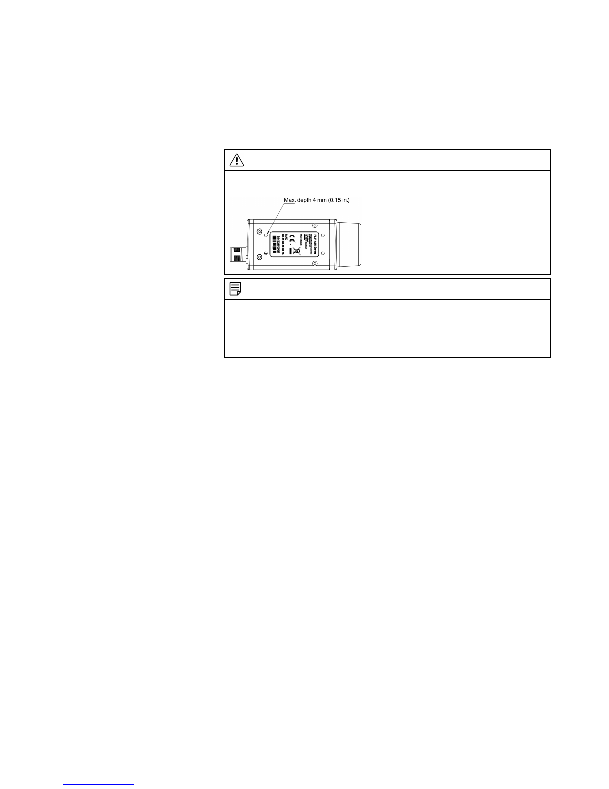
Applicability: FLIR Ax5.
Do not use screws that are too long. If you use screws that are too long, damage to the camera will occur. The maximum depth of the M3 holes is 4 mm (0.15 in.).
CAUTION
Do not point the infrared camera (with or without the lens cover) at strong energy sources, for example,
devices that cause laser radiation, or the sun. This can have an unwanted effect on the accuracy of the
camera. It can also cause damage to the detector in the camera.
CAUTION
Do not use the camera in temperatures more than +50°C (+122°F), unless other information is specified
in the user documentation or technical data. High temperatures can cause damage to the camera.
CAUTION
Do not apply solvents or equivalent liquids to the camera, the cables, or other items. Damage to the battery and injury to persons can occur.
CAUTION
Be careful when you clean the infrared lens. The lens has an anti-reflective coating which is easily damaged. Damage to the infrared lens can occur.
CAUTION
Do not use too much force to clean the infrared lens. This can cause damage to the anti-reflective
coating.
CAUTION
Applicability: Cameras with an automatic shutter that can be disabled.
Do not disable the automatic shutter in the camera for a long time period (a maximum of 30 minutes is
typical). If you disable the shutter for a longer time period, damage to the detector can occur.
NOTE
The encapsulation rating is only applicable when all the openings on the camera are sealed with their
correct covers, hatches, or caps. This includes the compartments for data storage, batteries, and
connectors.
CAUTION
Applicability: Cameras where you can remove the lens and expose the infrared detector.
Do not use the pressurized air from the pneumatic air systems in a workshop when you remove dust
from the detector. The air contains oil mist to lubricate the pneumatic tools and the pressure is too high.
Damage to the detector can occur.
#T559770; r.18834/22369; en-US
4
Page 11

Notice to user
3
3.1 User-to-user forums
Exchange ideas, problems, and infrared solutions with fellow thermographers around the
world in our user-to-user forums. To go to the forums, visit:
http://www.infraredtraining.com/community/boards/
3.2 Calibration
FLIR Systems recommends that you verify your calibration yearly. You can verify the calibration yourself or with the help of a FLIR Systems Partner. If preferred, FLIR Systems offers a calibration, adjustment, and general maintenance service.
3.3 Accuracy
For very accurate results, we recommend that you wait 5 minutes after you have started
the camera before measuring a temperature.
3.4 Disposal of electronic waste
As with most electronic products, this equipment must be disposed of in an environmentally friendly way, and in accordance with existing regulations for electronic waste.
Please contact your FLIR Systems representative for more details.
3.5 Training
To read about infrared training, visit:
• http://www.infraredtraining.com
• http://www.irtraining.com
• http://www.irtraining.eu
3.6 Documentation updates
Our manuals are updated several times per year, and we also issue product-critical notifications of changes on a regular basis.
To access the latest manuals and notifications, go to the Download tab at:
http://support.flir.com
It only takes a few minutes to register online. In the download area you will also find the
latest releases of manuals for our other products, as well as manuals for our historical
and obsolete products.
3.7 Important note about this manual
FLIR Systems issues generic manuals that cover several cameras within a model line.
This means that this manual may contain descriptions and explanations that do not apply
to your particular camera model.
#T559770; r.18834/22369; en-US
5
Page 12
Customer help
4
4.1 General
For customer help, visit:
http://support.flir.com
4.2 Submitting a question
To submit a question to the customer help team, you must be a registered user. It only
takes a few minutes to register online. If you only want to search the knowledgebase for
existing questions and answers, you do not need to be a registered user.
When you want to submit a question, make sure that you have the following information
to hand:
#T559770; r.18834/22369; en-US
6
Page 13

Customer help
4
• The camera model
• The camera serial number
• The communication protocol, or method, between the camera and your device (for example, HDMI, Ethernet, USB, or FireWire)
• Device type (PC/Mac/iPhone/iPad/Android device, etc.)
• Version of any programs from FLIR Systems
• Full name, publication number, and revision number of the manual
4.3 Downloads
On the customer help site you can also download the following:
• Firmware updates for your infrared camera.
• Program updates for your PC/Mac software.
• Freeware and evaluation versions of PC/Mac software.
• User documentation for current, obsolete, and historical products.
• Mechanical drawings (in *.dxf and *.pdf format).
• Cad data models (in *.stp format).
• Application stories.
• Technical datasheets.
• Product catalogs.
#T559770; r.18834/22369; en-US
7
Page 14
Introduction
5
The FLIR Ax5 cameras have features and functions that make them the natural choice
for anyone who uses PC software to solve problems. Available resolutions include 80 ×
64, 160 × 128, and 320 × 256 pixels.
Among their main features are GigE Vision and GenICam compliance, which makes
them plug-and-play when used with software packages such as IMAQ Vision and Halcon.
Key features:
• Very affordable.
• Compact (40 × 43 × 106 mm/1.57 × 1.69 × 4.17 in.).
• GigE Vision and GenICam compliant.
• GigE Vision lockable connector.
• PoE (power over Ethernet).
• 8-bit monochrome image streaming.
• 14-bit radiometric image streaming.
• High frame rates (60 Hz).
• Synchronization between cameras possible.
• 1x+1x GPIO.
• Compliant with any software that supports GenICam, including National Instruments
IMAQ Vision, Stemmers Common Vision Blox, and COGNEX Vision Pro.
• Lenses: 5°, 9°, 13°, 19°, and 25° (model-dependent).
Typical applications:
• Automation, thermal machine vision.
• Entry-level “high-speed” R&D.
#T559770; r.18834/22369; en-US
8
Page 15

List of accessories and services
6
Part number Product name
T198349 Base support
T198348
Cable kit Mains (UK,EU,US)
T127605ACC Cable M12 Pigtail
T127606ACC Cable M12 Sync
T951004ACC Ethernet cable CAT-6, 2m/6.6 ft.
DSW-10000 FLIR IR Camera Player
T198584 FLIR Tools
T198583 FLIR Tools+ (license only)
T198342ACC Focus adjustment tool
T911183 Gigabit PoE injector 16 W, with multi-plugs
ITC-ADV-3021 ITC Advanced General Thermography Course -
attendance, 1 pers.
ITC-ADV-3029 ITC Advanced General Thermography Course-
group of 10 pers.
ITC-CON-1001 ITC conference fee
ITC-EXP-1041 ITC Customized workshop - per person (per day)
ITC-EXP-1021 ITC In-house training - additional attendance 1
pers. (per day)
ITC-EXP-1029 ITC In-house training - group up to 10 pers. (per
day)
ITC-EXP-1050 ITC Infrared application and system consultancy
(per day)
ITC-CER-5105 ITC Level 1 Thermography Course - additional
student to on site class, 1 pers
ITC-CER-5101 ITC Level 1 Thermography Course - attendance,
1 pers.
ITC-CER-5109 ITC Level 1 Thermography Course – group of 10
pers.
ITC-CER-5205 ITC Level 2 Thermography Course - additional
student to on site class, 1 pers
ITC-CER-5201 ITC Level 2 Thermography Course - attendance,
1 pers.
ITC-CER-5209 ITC Level 2 Thermography Course – group of 10
pers.
ITC-EXP-2036 ITC R&D basics for industry users - group up to 6
pers. (2 days)
ITC-EXP-2025 ITC Short course Fever Screening - additional stu-
dent to on site class (2 days)
ITC-EXP-2021 ITC Short course Fever Screening - attendance 1
pers. (2 days)
ITC-EXP-2029 ITC Short course Fever Screening - inclusive 10
pers. (2 days)
ITC-EXP-1019 ITC Short course Introduction to thermography -
inclusive 10 pers. (1 day)
ITC-EXP-1011 ITC Short course Introduction to thermography
-attendance 1 pers. (1 day)
ITC-SOW-0001 ITC Software course - attendance 1 pers. (per
day)
ITC-SOW-0009 ITC Software course - group up to 10 pers. (per
day)
#T559770; r.18834/22369; en-US
9
Page 16

List of accessories and services
6
Part number Product name
ITC-EXP-1001 ITC Training 1 day - attendance 1 pers.
ITC-EXP-1009 ITC Training 1 day - group up to 10 pers.
ITC-EXP-2001 ITC Training 2 days - attendance 1 pers.
ITC-EXP-2009 ITC Training 2 days - group up to 10 pers.
ITC-EXP-3001 ITC Training 3 days - attendance 1 pers.
ITC-EXP-3009 ITC Training 3 days - group up to 10 pers.
ITC-TFT-0100 ITC travel time for instructor
T911112 PoE injector
T198392 Table stand kit
T198371 Transport case Ax5
ITC-TOL-1003 Travel and lodging expenses instructor (Center
and South Africa)
ITC-TOL-1001 Travel and lodging expenses instructor (Europe,
Balcans, Turkey, Cyprus)
ITC-TOL-1005 Travel and lodging expenses instructor (other)
ITC-TOL-1002 Travel and lodging expenses instructor (Russia/
GUS, Middle East, North Africa)
ITC-TOL-1004 Travel and lodging expenses instructor (various)
NOTE
FLIR Systems reserves the right to discontinue models, parts or accessories, and other items, or to
change specifications at any time without prior notice.
#T559770; r.18834/22369; en-US
10
Page 17
Mechanical installation
7
The camera unit has been designed to allow it to be mounted in any position. It has a
mounting interface on the bottom with four metric M3 holes.
WARNING
Do not use screws that are too long. Using screws that are too long will damage the camera. The maximum depth of the M3 holes is 4 mm (0.15 in.).
NOTE
The camera generates a considerable amount of heat during operation. This is normal. In order to
transfer this heat, it is recommended that the camera is mounted on a base support or a heat sink made
of a material that has a high capacity to transfer heat, e.g., aluminum. FLIR Systems provides P/N
T198349 (base support) for this purpose, but other base supports or heat sinks can be used.
The use of the base support is also strongly recommended in order to minimize temperature drift of the
infrared detector in the camera.
If the camera unit is to be permanently mounted on the application site, certain steps
have to be taken. The camera unit might need to be enclosed in a protective housing
and, depending on the ambient conditions (e.g., temperature), the housing may need to
be cooled by means of water or air. In very dusty conditions the installation might also
need to have a stream of pressurized air directed at the lens, in order to prevent dust
build-up.
When mounting the camera unit in harsh environments, every precaution should be taken when it comes to securing the unit. If the environment exposes the unit to severe vibrations, there may arise a need to secure the mounting screws by means of Loctite or
another industrial brand of thread-locking liquid, as well as to dampen the vibrations by
mounting the camera unit on a specially designed mounting base.
For further information regarding mounting recommendations and environmental enclosures, contact FLIR Systems.
The camera is typically powered using PoE (Power over Ethernet). A PoE injector and
cable kit are available from FLIR Systems. See the part numbers below.
• T198348, Cable kit mains (UK, EU, US).
• T911112, PoE injector.
• T951004ACC, Ethernet cable CAT-6, 2 m/6.6 ft.
#T559770; r.18834/22369; en-US
11
Page 18
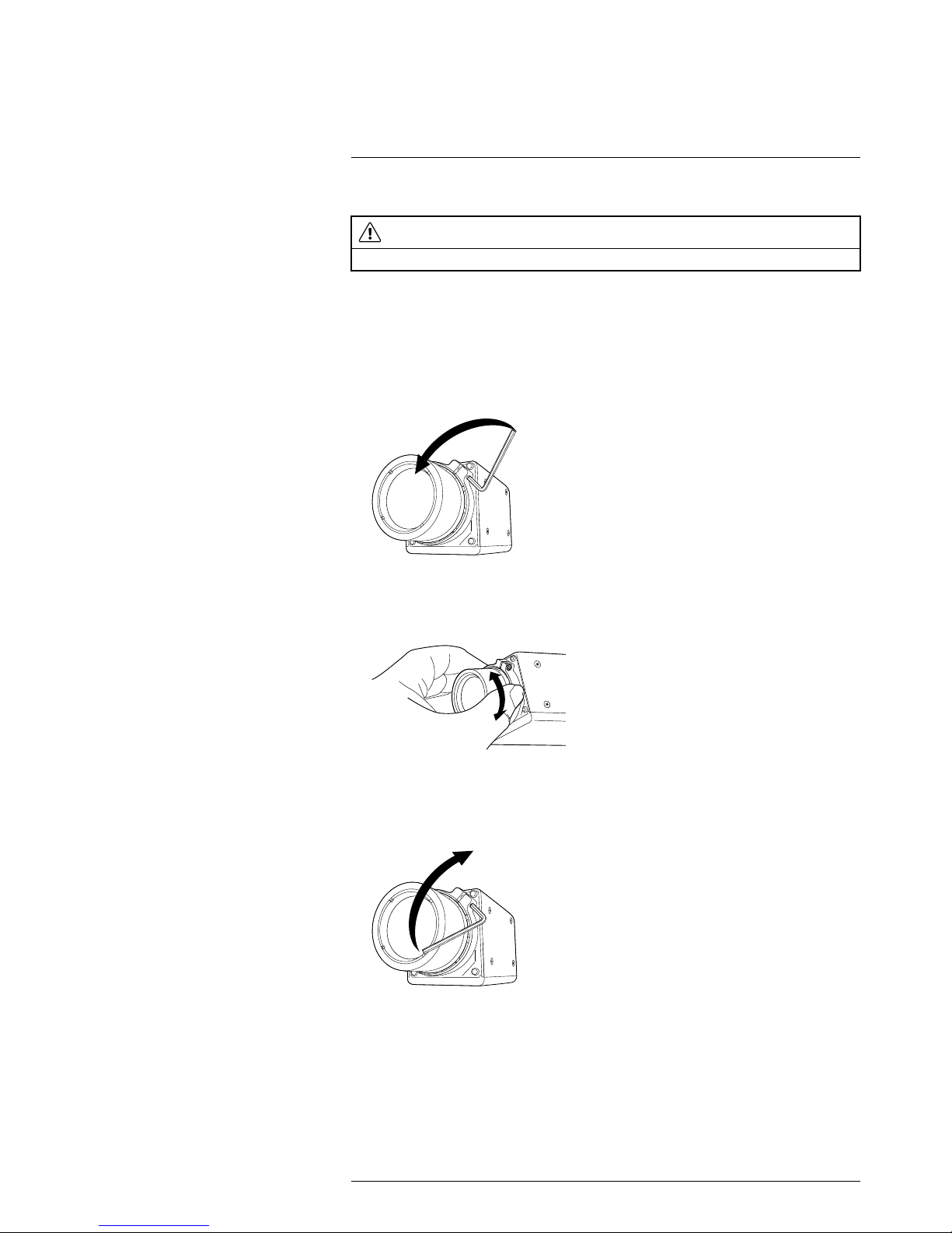
Focusing the camera
8
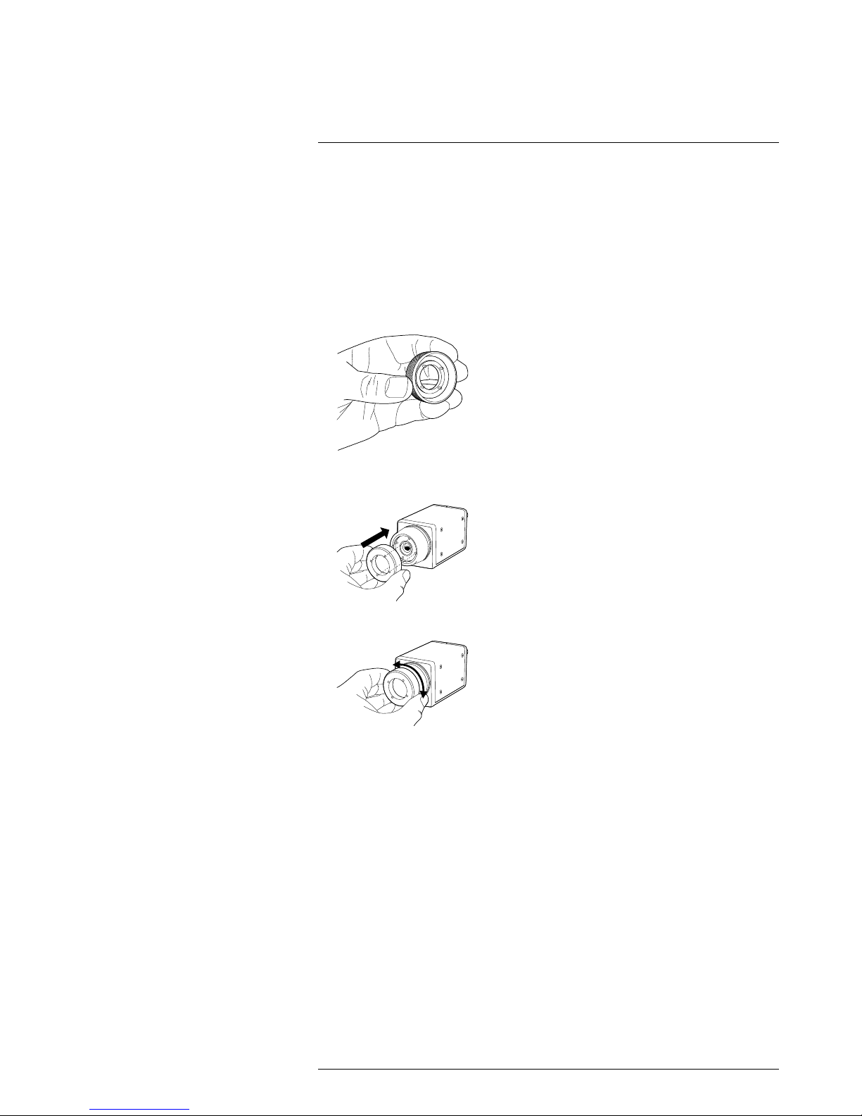
8.1 Focusing cameras with 5, 9, 13, and 19 mm lenses
8.1.1 Necessary tools
Focus adjustment tool (included in the package for cameras with 5, 9, 13, and 19 mm
lenses).
8.1.2 Procedure
Follow this procedure:
1. Note the four pegs on the inside of the focus adjustment tool.
2. Align the four pegs with the corresponding slots on the front of the lens, and push the
focus adjustment tool into position.
3. Rotate the lens.
#T559770; r.18834/22369; en-US
12
Page 19
Focusing the camera8
8.2 Focusing cameras with 25 mm lenses
CAUTION
Do not use the focus adjustment tool when focusing cameras with a 25 mm lens.
8.2.1 Necessary tools
Allen wrench, 1.5 mm.
8.2.2 Procedure
Follow this procedure:
1. Unlock the clamp by loosening the Allen screw.
2. Focus the camera by rotating the lens.
3. Lock the clamp by tightening the Allen screw.
#T559770; r.18834/22369; en-US
13
Page 20

Downloads
9
The principal software used to configure and control the camera is FLIR GEV Demo
1.3.0. This software is based on the PleoraeBus SDK and the runtime Pleora GEVPlayer
that comes with the SDK.
Downloads:
• http://support.flir.com/Ax5-software
• Link to download PureGEV SDK Sample (source code): http://support.flir.com/
SwDownload/app/RssSWDownload.aspx?ID=133
• Link to download FLIR GEV Demo 1.3.0 (installer): http://support.flir.com/SwDownload/app/RssSWDownload.aspx?ID=155
The camera is compliant with the following standards. Additional software and documentation resources can be downloaded from these sites.
• GeniCAM: http:www.genicam.org
• Gigabit Ethernet: http://www.ieee802.org/3
#T559770; r.18834/22369; en-US
14
Page 21

About I/O, synchronization, and
measurement
10
10.1 FLIR Ax5 General Purpose I/O
The FLIR Ax5 camera has one general-purpose input line and one output line that can
be used in control applications.
Typical usage:
• The output line is asserted when an alarm condition is met.
• The input line is used to trigger an action, for example saving an image.
The output line GPO+ is controlled by the register UserOutputValue. Set this register to
True to assert (level equal to GPIO_PWR) the GPO+ signal, and set to False to de-assert
(level is equal to GPIO_GND).
You can monitor the input line by reading the LineStatus register on a regular basis. The
LineStatus register will returnTrue if the input level is asserted (level equal to GPIO_PWR
voltage), and it will returnFalse if the input line is de-asserted (level is equal to GPIO_
GND).
Another option is to configure the camera to send a GigEVision event when the input line
state is changed. In order to configure the camera for event transmission you need to
modify the following registers:
PLC_Q7_Variable0
Enum
Set this register to PLC_I0 (enumeration value 2) to route the
GPI signal
EventSelector
Enum
Set this register to PLC_Interrupt_FIFO0_Q7 (enumeration
value 5)
EventNotification Enum Set this register to GigEVisionE-
vent (enumeration value 3)
To de-bounce the input signal you also might want to configure the LineDebounceFactor
register. This register controls the width of the window during which spurious transitions
from the input line are filtered out (in increments of ~480 ns). This register is 0 by default,
which means that the de-bouncing is disabled. The maximum value for this register is
65535, which corresponds to a maximum holding time of ~31 ms.
The FLIR GEV Demo 1.3 sample illustrates how to setup the event transmission. C++
source code is available in PureGEV SDK Sample.
Applicable downloads:
• Link to download PureGEV SDK Sample (source code): http://support.flir.com/
SwDownload/app/RssSWDownload.aspx?ID=133
• Link to download FLIR GEV Demo 1.3.0 (installer): http://support.flir.com/SwDownload/app/RssSWDownload.aspx?ID=155
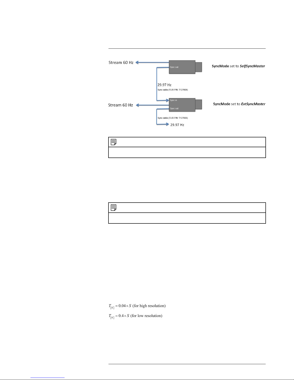
10.2 FLIR Ax5 synchronization
The camera provides an external sync channel that can be used to synchronize the
frame start between two cameras, one configured as the master and the other configured as the slave. It can also be used to synchronize the frame start of a camera with that
of another product.
#T559770; r.18834/22369; en-US
15
Page 22
About I/O, synchronization, and measurement
10
Figure 10.1 Master/slave synchronization between two FLIR Ax5 cameras (NTSC).
NOTE
External synchronization can be applied but only by using an input signal with a frequency of 29.97 Hz
(NTSC).
• The signal voltage (relative to digital GND) is 3.3 V.
• The pulse width (minimum) is 100 ns (will be extended to 1 μs).
Note that the synchronization mode is not persistent. The camera will always return to
SyncMode Disabled after reset or power cycling.
For slow configurations (9 Hz), the output frame rate is a fraction of the sync pulse rate.
Because there is ambiguity as to which received pulse triggers the frame timing, FLIR
does not recommend using the external sync interface with a slow-configured camera.
NOTE
The only difference between ExtSyncMaster and SelfSyncSlave mode is that the incoming sync signal
is relayed to the SYNC_OUT port if set to ExtSyncMaster.
10.3 FLIR Ax5 measurement
The FLIR Ax5 camera has an option to output 14-bit digital video that is temperature
linear.
Each count in the temperature-linear video corresponds to either 0.04 K or 0.4 K in 14-bit
video, depending on the selected resolution.
Temperature-linear output is enabled or disabled with the feature register:
TemperatureLinearMode: On (1) or Off (0)
Temparture-linear resolution is determined with the feature register:
TemperatureLinearResolution: Low 0.4 K (0) or High 0.04 K (1)
If TemperatureLinearMode is On, the signal-to-temperature mapping is calculated us-
ing the equations
S corresponds to the 14-bit pixel value.
If the TemperatureLinearMode is Off, then the camera provides registers that can be
used to convert signal values to temperature. For each measurement range (or gain
mode) there is a set of register values that is used for this conversion.
#T559770; r.18834/22369; en-US
16
Page 23
About I/O, synchronization, and measurement
10
The conversion from the corrected signal S to the temperature T
[K]
is performed using
the external RBFO values for the selected lens and gain mode. The signal-to-temperature mapping is calculated using the equation
ln(x) is the base-e logarithm of the x parameter, and S corresponds to the 14-bit pixel
value.
Register name Type
R Integer
B Float
F Float
O Float (handles only positive vales)
OInt Integer (same as O but handles negative values)
Please note that these registers will be automatically updated when switching between
the high gain mode and the low gain mode.
The FLIR GEV Demo sample illustrates how to use this conversion formula.
You also have the option to do your own one-point calibration by adjusting the offset val-
ue (register OInt) by pointing the camera at an accurately known temperature. Knowing
the temperature, you can then calculate the offset value and update the OInt register.
The FLIR GEV Demo sample illustrates how to perform this kind of calibration. Please
note that you will need to save the current settings if you want the new offset value to be
persistent. Use the command register SensorSetDefaults to set all current settings as
power on defaults.
There are additional registers that also affect the temperature linear output. These registers are grouped together as Object Parameter registers. These registers only affect the
transformation of detector signal values to temperature values when the camera is in
temperature linear mode.
ReflectedTemperature: The estimated reflected background temperature for the target
scene.
ObjectEmissivity: The target scene emissivity factor. The default value is 1.0.
WindowTransmission: The estimated transmission factor for the protective window.
The default value is 1.0.
WindowTemperature: The external window temperature T
win
(in kelvin).
AtmosphericTransmission: The estimated transmission factor for the atmosphere between the camera and the scene.
AtmosphericTemperature: The estimated temperature T
atm
for the atmosphere be-
tween the camera and the scene.
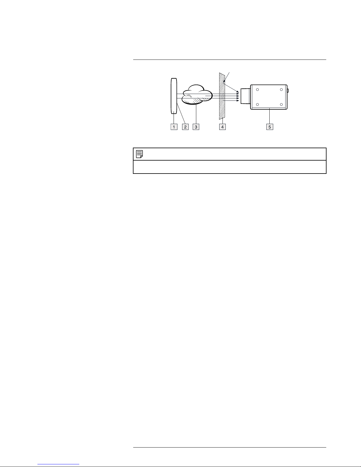
The correction for scene parameters is extended to include the following parameters:
#T559770; r.18834/22369; en-US
17
Page 24
About I/O, synchronization, and measurement
10
Figure 10.2 1: Scene, T
scene
; 2: Reflected background temperature; 3: Atmosphere, T
Atm
; 4: External win-
dow, T
win
; 5: Infrared camera.
NOTE
The default values for the object parameters are set to values that will have no impact on the conversion
between detector signal values and corrected signal values.
#T559770; r.18834/22369; en-US
18
Page 25

Technical data
11
11.1 Online field-of-view calculator
Please visit http://support.flir.com and click the FLIR Ax5 camera for field-of-view tables
for all lens–camera combinations in this camera series.
11.2 Note about technical data
FLIR Systems reserves the right to change specifications at any time without prior notice.
Please check http://support.flir.com for latest changes.
#T559770; r.18834/22369; en-US
19
Page 26

Technical data11
11.3 FLIR A15 f=19 mm
P/N: 62319-0101
Rev.: 22369
General description
The FLIR A15 has features and functions that make it the natural choice for anyone who uses PC software to solve problems and for whom 160 × 128 pixel resolution is sufficient.
Among its main features are GigE Vision and GenICam compliance, which makes it plug-and-play when
used with software packages such as IMAQ Vision and Halcon.
Key features:
• Very affordable.
• Compact (40 mm × 43 mm × 106 mm).
• GigE Vision and GenICam compliant.
• GigE Vision lockable connector.
• PoE (power over Ethernet).
• 8-bit 160 × 128 pixel images streamed at 60 Hz, signal linear.
• 14-bit 160 × 128 pixel images streamed at 60 Hz, signal and temperature linear.
• High frame rates (60 Hz).
• Synchronization between cameras possible.
• 1x+1x GPIO.
• Compliant with any software that supports GenICam, including National Instruments IMAQ Vision,
Stemmers Common Vision Blox, and COGNEX Vision Pro.
Typical applications:
• Automation and thermal machine vision.
• Entry level “high-speed” R&D.
Imaging and optical data
IR resolution 160 × 128 pixels
Thermal sensitivity/NETD < 0.05°C @ +30°C (+86°F) / 50 mK
Field of view (FOV)
25° × 19°
Focal length 19 mm (0.75 in.)
Spatial resolution (IFOV)
2.63 mrad
F-number 1.25
Image frequency 60 Hz
Focus Fixed
Detector data
Detector type Focal Plane Array (FPA), Uncooled VOX
microbolometer
Spectral range
7.5–13 µm
Detector pitch 50 µm
Detector time constant Typical 12 ms
Measurement
Object temperature range
• –25 to +135°C (–13 to 275°F)
• –40 to +550°C (–40 to +1022°F)
Accuracy ±5°C (±9°F) or ±5% of reading
Ethernet
Ethernet Control and image
Ethernet, type Gigabit Ethernet
Ethernet, standard IEEE 802.3
Ethernet, connector type RJ-45
#T559770; r.18834/22369; en-US
20
Page 27

Technical data11
Ethernet
Ethernet, communication GigE Vision ver. 1.2
Client API GenICam compliant
Ethernet, image streaming 8-bit monochrome @ 60 Hz
• Signal linear/ DDE
• Automatic/ Manual
• Flip H&V
14-bit 160 × 128 pixels @ 60 Hz
• Signal linear/ DDE
• Temperature linear
GigE Vision and GenICam compatible
Ethernet, power Power over Ethernet, PoE IEEE 802.3af class 0
Power
Ethernet, protocols TCP, UDP,ICMP, IGMP, DHCP, GigEVision
Digital input/output
Digital input, purpose General purpose
Digital input 1× opto-isolated, "0" <2, "1"=2-12 VDC. NOTE:
Maximum input 12 VDC. If the input is above 12
VDC without a resistor in series there is a risk of
damaging the input. If the input is 24 VDC use a
1.2 kΩ resistor in series. In that case "1" = 3-24
VDC.
Digital output, purpose General purpose Output to ext. device (program-
matically set)
Digital output 1× opto-isolated, 2–40 VDC, max 185 mA
Digital I/O, isolation voltage 500 VRMS
Digital I/O, supply voltage 2–40 VDC, max 200 mA
Digital I/O, connector type 12-pole M12 connector (shared with Digital Syn-
chronization and External power)
Synchronization In, purpose
Frame sync In to control camera
Synchronization In 1×, non-isolated
Synchronization In, type LVC Buffer @3.3V, “0” <0.8 V, “1”>2.0 V.
Synchronization Out, purpose Frame sync Out to control another Ax5 camera
Synchronization Out 1×, non-isolated
Synchronization Out, type LVC Buffer @ 3.3V, ”0”=24 MA max, “1”= –24 mA
max.
Digital Synchronization, connector type 12-pole M12 connector (shared with Digital I/O
and External power)
Power system
External power operation 12/24 VDC, < 3.5 W nominal < 6.0 W absolute
max
External power, connector type 12-pole M12 connector (shared with Digital I/O
and Digital Synchronization )
Voltage Allowed range 10–30 VDC
Environmental data
Operating temperature range –15°C to +50°C (+5°F to +122°F)
Storage temperature range –40°C to +70°C (–40°F to +158°F)
Humidity (operating and storage) IEC 60068-2-30/24 h 95% relative humidity +25°C
to +40°C (+77°F to +104°F)
#T559770; r.18834/22369; en-US
21
Page 28

Technical data11
Environmental data
EMC
• EN 61000-6-2 (Immunity)
• EN 61000-6-3 (Emission)
• FCC 47 CFR Part 15 Class B (Emission)
Encapsulation IP 40 (IEC 60529) with base support mounted
Shock 25 g (IEC 60068-2-27)
Vibration
2 g (IEC 60068-2-6)
Physical data
Weight 0.200 kg (0.44 lb.)
Camera size (L × W × H) 106 × 40 × 43 mm (4.2 × 1.6 × 1.7 in.)
Tripod mounting UNC ¼"-20 (on three sides)
Base mounting 4 × M3 thread mounting holes (bottom)
Housing material Magnesium and aluminum
Shipping information
Packaging, type
Cardboard box
List of contents
• Infrared camera with lens
• FLIR Tools download card
• Focus adjustment tool
• Printed documentation
• User documentation CD-ROM
Packaging, weight
Packaging, size 295 × 200 × 105 mm (11.6 × 7.9 × 4.1 in.)
EAN-13 7332558003992
4743254000605 (Estonia plant)
UPC-12
845188003555
Country of origin Sweden
Supplies & accessories:
• T951004ACC; Ethernet cable CAT-6, 2m/6.6 ft.
• T198349; Base support
• T198348; Cable kit Mains (UK,EU,US)
• T911112; PoE injector
• T198392; Table stand kit
• T911183; Gigabit PoE injector 16 W, with multi-plugs
• T127605ACC; Cable M12 Pigtail
• T127606ACC; Cable M12 Sync
• T198342ACC; Focus adjustment tool
• T198584; FLIR Tools
• T198583; FLIR Tools+ (license only)
• DSW-10000; FLIR IR Camera Player
#T559770; r.18834/22369; en-US
22
Page 29

Technical data11
11.4 FLIR A15 f=19 mm (7.5 Hz)
P/N: 64319-0101
Rev.: 22369
General description
The FLIR A15 has features and functions that make it the natural choice for anyone who uses PC software to solve problems and for whom 160 × 128 pixel resolution is sufficient.
Among its main features are GigE Vision and GenICam compliance, which makes it plug-and-play when
used with software packages such as IMAQ Vision and Halcon.
Key features:
• Very affordable.
• Compact (40 mm × 43 mm × 106 mm).
• GigE Vision and GenICam compliant.
• GigE Vision lockable connector.
• PoE (power over Ethernet).
• 8-bit 160 × 128 pixel images streamed at 7.5 Hz, signal linear.
• 14-bit 160 × 128 pixel images streamed at 7.5 Hz, signal and temperature linear.
• Synchronization between cameras possible.
• 1x+1x GPIO.
• Compliant with any software that supports GenICam, including National Instruments IMAQ Vision,
Stemmers Common Vision Blox, and COGNEX Vision Pro.
Typical applications:
• Automation and thermal machine vision.
• Entry level “high-speed” R&D.
Imaging and optical data
IR resolution 160 × 128 pixels
Thermal sensitivity/NETD < 0.05°C @ +30°C (+86°F) / 50 mK
Field of view (FOV)
25° × 19°
Focal length 19 mm (0.75 in.)
Spatial resolution (IFOV)
2.63 mrad
F-number 1.25
Image frequency 7.5 Hz
Focus Fixed
Detector data
Detector type
Focal Plane Array (FPA), Uncooled VOX
microbolometer
Spectral range
7.5–13 µm
Detector pitch 50 µm
Detector time constant Typical 12 ms
Measurement
Object temperature range
• –25 to +135°C (–13 to 275°F)
• –40 to +550°C (–40 to +1022°F)
Accuracy ±5°C (±9°F) or ±5% of reading
Ethernet
Ethernet Control and image
Ethernet, type
Gigabit Ethernet
Ethernet, standard IEEE 802.3
Ethernet, connector type RJ-45
Ethernet, communication GigE Vision ver. 1.2
Client API GenICam compliant
#T559770; r.18834/22369; en-US
23
Page 30

Technical data11
Ethernet
Ethernet, image streaming 8-bit monochrome @ 7.5 Hz
• Signal linear/ DDE
• Automatic/ Manual
• Flip H&V
14-bit 160 × 128 pixels @ 7.5 Hz
• Signal linear/ DDE
• Temperature linear
GigE Vision and GenICam compatible
Ethernet, power Power over Ethernet, PoE IEEE 802.3af class 0
Power
Ethernet, protocols
TCP, UDP,ICMP, IGMP, DHCP, GigEVision
Digital input/output
Digital input, purpose
General purpose
Digital input
1× opto-isolated, "0" <2, "1"=2-12 VDC. NOTE:
Maximum input 12 VDC. If the input is above 12
VDC without a resistor in series there is a risk of
damaging the input. If the input is 24 VDC use a
1.2 kΩ resistor in series. In that case "1" = 3-24
VDC.
Digital output, purpose
General purpose Output to ext. device (programmatically set)
Digital output
1× opto-isolated, 2–40 VDC, max 185 mA
Digital I/O, isolation voltage 500 VRMS
Digital I/O, supply voltage 2–40 VDC, max 200 mA
Digital I/O, connector type 12-pole M12 connector (shared with Digital Syn-
chronization and External power)
Synchronization In, purpose Frame sync In to control camera
Synchronization In 1×, non-isolated
Synchronization In, type LVC Buffer @3.3V, “0” <0.8 V, “1”>2.0 V.
Synchronization Out, purpose Frame sync Out to control another Ax5 camera
Synchronization Out
1×, non-isolated
Synchronization Out, type LVC Buffer @ 3.3V, ”0”=24 MA max, “1”= –24 mA
max.
Digital Synchronization, connector type 12-pole M12 connector (shared with Digital I/O
and External power)
Power system
External power operation 12/24 VDC, < 3.5 W nominal < 6.0 W absolute
max
External power, connector type 12-pole M12 connector (shared with Digital I/O
and Digital Synchronization )
Voltage
Allowed range 10–30 VDC
Environmental data
Operating temperature range –15°C to +50°C (+5°F to +122°F)
Storage temperature range –40°C to +70°C (–40°F to +158°F)
Humidity (operating and storage) IEC 60068-2-30/24 h 95% relative humidity +25°C
to +40°C (+77°F to +104°F)
EMC
• EN 61000-6-2 (Immunity)
• EN 61000-6-3 (Emission)
• FCC 47 CFR Part 15 Class B (Emission)
Encapsulation IP 40 (IEC 60529) with base support mounted
#T559770; r.18834/22369; en-US
24
Page 31

Technical data11
Environmental data
Shock 25 g (IEC 60068-2-27)
Vibration 2 g (IEC 60068-2-6)
Physical data
Weight 0.200 kg (0.44 lb.)
Camera size (L × W × H) 106 × 40 × 43 mm (4.2 × 1.6 × 1.7 in.)
Tripod mounting UNC ¼"-20 (on three sides)
Base mounting 4 × M3 thread mounting holes (bottom)
Housing material Magnesium and aluminum
Shipping information
Packaging, type Cardboard box
List of contents
• Infrared camera with lens
• FLIR Tools download card
• Focus adjustment tool
• Printed documentation
• User documentation CD-ROM
Packaging, weight
Packaging, size 295 × 200 × 105 mm (11.6 × 7.9 × 4.1 in.)
EAN-13 7332558005668
UPC-12
845188005870
Country of origin Sweden
Supplies & accessories:
• T951004ACC; Ethernet cable CAT-6, 2m/6.6 ft.
• T198349; Base support
• T198348; Cable kit Mains (UK,EU,US)
• T911112; PoE injector
• T198392; Table stand kit
• T911183; Gigabit PoE injector 16 W, with multi-plugs
• T127605ACC; Cable M12 Pigtail
• T127606ACC; Cable M12 Sync
• T198342ACC; Focus adjustment tool
• T198584; FLIR Tools
• T198583; FLIR Tools+ (license only)
• DSW-10000; FLIR IR Camera Player
#T559770; r.18834/22369; en-US
25
Page 32

Technical data11
11.5 FLIR A15 f=9 mm
P/N: 62309-0101
Rev.: 22369
General description
The FLIR A15 has features and functions that make it the natural choice for anyone who uses PC software to solve problems and for whom 160 × 128 pixel resolution is sufficient.
Among its main features are GigE Vision and GenICam compliance, which makes it plug-and-play when
used with software packages such as IMAQ Vision and Halcon.
Key features:
• Very affordable.
• Compact (40 mm × 43 mm × 106 mm).
• GigE Vision and GenICam compliant.
• GigE Vision lockable connector.
• PoE (power over Ethernet).
• 8-bit 160 × 128 pixel images streamed at 60 Hz, signal linear.
• 14-bit 160 × 128 pixel images streamed at 60 Hz, signal and temperature linear.
• High frame rates (60 Hz).
• Synchronization between cameras possible.
• 1x+1x GPIO.
• Compliant with any software that supports GenICam, including National Instruments IMAQ Vision,
Stemmers Common Vision Blox, and COGNEX Vision Pro.
Typical applications:
• Automation and thermal machine vision.
• Entry level “high-speed” R&D.
Imaging and optical data
IR resolution 160 × 128 pixels
Thermal sensitivity/NETD < 0.05°C @ +30°C (+86°F) / 50 mK
Field of view (FOV)
48° × 39°
Focal length 9 mm (0.35 in.)
Spatial resolution (IFOV)
5.56 mrad
F-number 1.25
Image frequency 60 Hz
Focus Fixed
Detector data
Detector type Focal Plane Array (FPA), Uncooled VOX
microbolometer
Spectral range
7.5–13 µm
Detector pitch 50 µm
Detector time constant Typical 12 ms
Measurement
Object temperature range
• –25 to +135°C (–13 to 275°F)
• –40 to +550°C (–40 to +1022°F)
Accuracy ±5°C (±9°F) or ±5% of reading
Ethernet
Ethernet Control and image
Ethernet, type Gigabit Ethernet
Ethernet, standard IEEE 802.3
Ethernet, connector type RJ-45
#T559770; r.18834/22369; en-US
26
Page 33

Technical data11
Ethernet
Ethernet, communication GigE Vision ver. 1.2
Client API GenICam compliant
Ethernet, image streaming 8-bit monochrome @ 60 Hz
• Signal linear/ DDE
• Automatic/ Manual
• Flip H&V
14-bit 160 × 128 pixels @ 60 Hz
• Signal linear/ DDE
• Temperature linear
GigE Vision and GenICam compatible
Ethernet, power Power over Ethernet, PoE IEEE 802.3af class 0
Power
Ethernet, protocols TCP, UDP,ICMP, IGMP, DHCP, GigEVision
Digital input/output
Digital input, purpose General purpose
Digital input 1× opto-isolated, "0" <2, "1"=2-12 VDC. NOTE:
Maximum input 12 VDC. If the input is above 12
VDC without a resistor in series there is a risk of
damaging the input. If the input is 24 VDC use a
1.2 kΩ resistor in series. In that case "1" = 3-24
VDC.
Digital output, purpose General purpose Output to ext. device (program-
matically set)
Digital output 1× opto-isolated, 2–40 VDC, max 185 mA
Digital I/O, isolation voltage 500 VRMS
Digital I/O, supply voltage 2–40 VDC, max 200 mA
Digital I/O, connector type 12-pole M12 connector (shared with Digital Syn-
chronization and External power)
Synchronization In, purpose
Frame sync In to control camera
Synchronization In 1×, non-isolated
Synchronization In, type LVC Buffer @3.3V, “0” <0.8 V, “1”>2.0 V.
Synchronization Out, purpose Frame sync Out to control another Ax5 camera
Synchronization Out 1×, non-isolated
Synchronization Out, type LVC Buffer @ 3.3V, ”0”=24 MA max, “1”= –24 mA
max.
Digital Synchronization, connector type 12-pole M12 connector (shared with Digital I/O
and External power)
Power system
External power operation 12/24 VDC, < 3.5 W nominal < 6.0 W absolute
max
External power, connector type 12-pole M12 connector (shared with Digital I/O
and Digital Synchronization )
Voltage Allowed range 10–30 VDC
Environmental data
Operating temperature range –15°C to +50°C (+5°F to +122°F)
Storage temperature range –40°C to +70°C (–40°F to +158°F)
Humidity (operating and storage) IEC 60068-2-30/24 h 95% relative humidity +25°C
to +40°C (+77°F to +104°F)
#T559770; r.18834/22369; en-US
27
Page 34

Technical data11
Environmental data
EMC
• EN 61000-6-2 (Immunity)
• EN 61000-6-3 (Emission)
• FCC 47 CFR Part 15 Class B (Emission)
Encapsulation IP 40 (IEC 60529) with base support mounted
Shock 25 g (IEC 60068-2-27)
Vibration
2 g (IEC 60068-2-6)
Physical data
Weight 0.200 kg (0.44 lb.)
Camera size (L × W × H) 106 × 40 × 43 mm (4.2 × 1.6 × 1.7 in.)
Tripod mounting UNC ¼"-20 (on three sides)
Base mounting 4 × M3 thread mounting holes (bottom)
Housing material Magnesium and aluminum
Shipping information
Packaging, type
Cardboard box
List of contents
• Infrared camera with lens
• FLIR Tools download card
• Focus adjustment tool
• Printed documentation
• User documentation CD-ROM
Packaging, weight
Packaging, size 295 × 200 × 105 mm (11.6 × 7.9 × 4.1 in.)
EAN-13 7332558003978
4743254000599 (Estonia plant)
UPC-12
845188003548
Country of origin Sweden
Supplies & accessories:
• T951004ACC; Ethernet cable CAT-6, 2m/6.6 ft.
• T198349; Base support
• T198348; Cable kit Mains (UK,EU,US)
• T911112; PoE injector
• T198392; Table stand kit
• T911183; Gigabit PoE injector 16 W, with multi-plugs
• T127605ACC; Cable M12 Pigtail
• T127606ACC; Cable M12 Sync
• T198342ACC; Focus adjustment tool
• T198584; FLIR Tools
• T198583; FLIR Tools+ (license only)
• DSW-10000; FLIR IR Camera Player
#T559770; r.18834/22369; en-US
28
Page 35

Technical data11
11.6 FLIR A15 f=9 mm (7.5 Hz)
P/N: 64309-0101
Rev.: 22369
General description
The FLIR A15 has features and functions that make it the natural choice for anyone who uses PC software to solve problems and for whom 160 × 128 pixel resolution is sufficient.
Among its main features are GigE Vision and GenICam compliance, which makes it plug-and-play when
used with software packages such as IMAQ Vision and Halcon.
Key features:
• Very affordable.
• Compact (40 mm × 43 mm × 106 mm).
• GigE Vision and GenICam compliant.
• GigE Vision lockable connector.
• PoE (power over Ethernet).
• 8-bit 160 × 128 pixel images streamed at 7.5 Hz, signal linear.
• 14-bit 160 × 128 pixel images streamed at 7.5 Hz, signal and temperature linear.
• Synchronization between cameras possible.
• 1x+1x GPIO.
• Compliant with any software that supports GenICam, including National Instruments IMAQ Vision,
Stemmers Common Vision Blox, and COGNEX Vision Pro.
Typical applications:
• Automation and thermal machine vision.
• Entry level “high-speed” R&D.
Imaging and optical data
IR resolution 160 × 128 pixels
Thermal sensitivity/NETD < 0.05°C @ +30°C (+86°F) / 50 mK
Field of view (FOV)
48° × 39°
Focal length 9 mm (0.35 in.)
Spatial resolution (IFOV)
5.56 mrad
F-number 1.25
Image frequency 7.5 Hz
Focus Fixed
Detector data
Detector type
Focal Plane Array (FPA), Uncooled VOX
microbolometer
Spectral range
7.5–13 µm
Detector pitch 50 µm
Detector time constant Typical 12 ms
Measurement
Object temperature range
• –25 to +135°C (–13 to 275°F)
• –40 to +550°C (–40 to +1022°F)
Accuracy ±5°C (±9°F) or ±5% of reading
Ethernet
Ethernet Control and image
Ethernet, type
Gigabit Ethernet
Ethernet, standard IEEE 802.3
Ethernet, connector type RJ-45
Ethernet, communication GigE Vision ver. 1.2
Client API GenICam compliant
#T559770; r.18834/22369; en-US
29
Page 36

Technical data11
Ethernet
Ethernet, image streaming 8-bit monochrome @ 7.5 Hz
• Signal linear/ DDE
• Automatic/ Manual
• Flip H&V
14-bit 160 × 128 pixels @ 7.5 Hz
• Signal linear/ DDE
• Temperature linear
GigE Vision and GenICam compatible
Ethernet, power Power over Ethernet, PoE IEEE 802.3af class 0
Power
Ethernet, protocols
TCP, UDP,ICMP, IGMP, DHCP, GigEVision
Digital input/output
Digital input, purpose
General purpose
Digital input
1× opto-isolated, "0" <2, "1"=2-12 VDC. NOTE:
Maximum input 12 VDC. If the input is above 12
VDC without a resistor in series there is a risk of
damaging the input. If the input is 24 VDC use a
1.2 kΩ resistor in series. In that case "1" = 3-24
VDC.
Digital output, purpose
General purpose Output to ext. device (programmatically set)
Digital output
1× opto-isolated, 2–40 VDC, max 185 mA
Digital I/O, isolation voltage 500 VRMS
Digital I/O, supply voltage 2–40 VDC, max 200 mA
Digital I/O, connector type 12-pole M12 connector (shared with Digital Syn-
chronization and External power)
Synchronization In, purpose Frame sync In to control camera
Synchronization In 1×, non-isolated
Synchronization In, type LVC Buffer @3.3V, “0” <0.8 V, “1”>2.0 V.
Synchronization Out, purpose Frame sync Out to control another Ax5 camera
Synchronization Out
1×, non-isolated
Synchronization Out, type LVC Buffer @ 3.3V, ”0”=24 MA max, “1”= –24 mA
max.
Digital Synchronization, connector type 12-pole M12 connector (shared with Digital I/O
and External power)
Power system
External power operation 12/24 VDC, < 3.5 W nominal < 6.0 W absolute
max
External power, connector type 12-pole M12 connector (shared with Digital I/O
and Digital Synchronization )
Voltage
Allowed range 10–30 VDC
Environmental data
Operating temperature range –15°C to +50°C (+5°F to +122°F)
Storage temperature range –40°C to +70°C (–40°F to +158°F)
Humidity (operating and storage) IEC 60068-2-30/24 h 95% relative humidity +25°C
to +40°C (+77°F to +104°F)
EMC
• EN 61000-6-2 (Immunity)
• EN 61000-6-3 (Emission)
• FCC 47 CFR Part 15 Class B (Emission)
Encapsulation IP 40 (IEC 60529) with base support mounted
#T559770; r.18834/22369; en-US
30
Page 37

Technical data11
Environmental data
Shock 25 g (IEC 60068-2-27)
Vibration 2 g (IEC 60068-2-6)
Physical data
Weight 0.200 kg (0.44 lb.)
Camera size (L × W × H) 106 × 40 × 43 mm (4.2 × 1.6 × 1.7 in.)
Tripod mounting UNC ¼"-20 (on three sides)
Base mounting 4 × M3 thread mounting holes (bottom)
Housing material Magnesium and aluminum
Shipping information
Packaging, type Cardboard box
List of contents
• Infrared camera with lens
• FLIR Tools download card
• Focus adjustment tool
• Printed documentation
• User documentation CD-ROM
Packaging, weight
Packaging, size 295 × 200 × 105 mm (11.6 × 7.9 × 4.1 in.)
EAN-13 7332558005644
UPC-12
845188005856
Country of origin Sweden
Supplies & accessories:
• T951004ACC; Ethernet cable CAT-6, 2m/6.6 ft.
• T198349; Base support
• T198348; Cable kit Mains (UK,EU,US)
• T911112; PoE injector
• T198392; Table stand kit
• T911183; Gigabit PoE injector 16 W, with multi-plugs
• T127605ACC; Cable M12 Pigtail
• T127606ACC; Cable M12 Sync
• T198342ACC; Focus adjustment tool
• T198584; FLIR Tools
• T198583; FLIR Tools+ (license only)
• DSW-10000; FLIR IR Camera Player
#T559770; r.18834/22369; en-US
31
Page 38

Technical data11
11.7 FLIR A15 f=9 mm with SC kit
P/N: 62309-0102
Rev.: 22369
General description
The FLIR A15 has features and functions that make it the natural choice for anyone who uses PC software to solve problems and for whom 160 × 128 pixel resolution is sufficient.
Among its main features are GigE Vision and GenICam compliance, which makes it plug-and-play when
used with software packages such as IMAQ Vision and Halcon.
Key features:
• Very affordable.
• Compact (40 mm × 43 mm × 106 mm).
• GigE Vision and GenICam compliant.
• GigE Vision lockable connector.
• PoE (power over Ethernet).
• 8-bit 160 × 128 pixel images streamed at 60 Hz, signal linear.
• 14-bit 160 × 128 pixel images streamed at 60 Hz, signal and temperature linear.
• High frame rates (60 Hz).
• Synchronization between cameras possible.
• 1x+1x GPIO.
• Compliant with any software that supports GenICam, including National Instruments IMAQ Vision,
Stemmers Common Vision Blox, and COGNEX Vision Pro.
Typical applications:
• Automation and thermal machine vision.
• Entry level “high-speed” R&D.
Imaging and optical data
IR resolution 160 × 128 pixels
Thermal sensitivity/NETD < 0.05°C @ +30°C (+86°F) / 50 mK
Field of view (FOV)
48° × 39°
Focal length 9 mm (0.35 in.)
Spatial resolution (IFOV)
5.56 mrad
F-number 1.25
Image frequency 60 Hz
Focus Fixed
Detector data
Detector type Focal Plane Array (FPA), Uncooled VOX
microbolometer
Spectral range
7.5–13 µm
Detector pitch 50 µm
Detector time constant Typical 12 ms
Measurement
Object temperature range
• –25 to +135°C (–13 to 275°F)
• –40 to +550°C (–40 to +1022°F)
Accuracy ±5°C (±9°F) or ±5% of reading
Ethernet
Ethernet Control and image
Ethernet, type Gigabit Ethernet
Ethernet, standard IEEE 802.3
Ethernet, connector type RJ-45
#T559770; r.18834/22369; en-US
32
Page 39

Technical data11
Ethernet
Ethernet, communication GigE Vision ver. 1.2
Client API GenICam compliant
Ethernet, image streaming 8-bit monochrome @ 60 Hz
• Signal linear/ DDE
• Automatic/ Manual
• Flip H&V
14-bit 160 × 128 pixels @ 60 Hz
• Signal linear/ DDE
• Temperature linear
GigE Vision and GenICam compatible
Ethernet, power Power over Ethernet, PoE IEEE 802.3af class 0
Power
Ethernet, protocols TCP, UDP,ICMP, IGMP, DHCP, GigEVision
Digital input/output
Digital input, purpose General purpose
Digital input 1× opto-isolated, "0" <2, "1"=2-12 VDC. NOTE:
Maximum input 12 VDC. If the input is above 12
VDC without a resistor in series there is a risk of
damaging the input. If the input is 24 VDC use a
1.2 kΩ resistor in series. In that case "1" = 3-24
VDC.
Digital output, purpose General purpose Output to ext. device (program-
matically set)
Digital output 1× opto-isolated, 2–40 VDC, max 185 mA
Digital I/O, isolation voltage 500 VRMS
Digital I/O, supply voltage 2–40 VDC, max 200 mA
Digital I/O, connector type 12-pole M12 connector (shared with Digital Syn-
chronization and External power)
Synchronization In, purpose
Frame sync In to control camera
Synchronization In 1×, non-isolated
Synchronization In, type LVC Buffer @3.3V, “0” <0.8 V, “1”>2.0 V.
Synchronization Out, purpose Frame sync Out to control another Ax5 camera
Synchronization Out 1×, non-isolated
Synchronization Out, type LVC Buffer @ 3.3V, ”0”=24 MA max, “1”= –24 mA
max.
Digital Synchronization, connector type 12-pole M12 connector (shared with Digital I/O
and External power)
Power system
External power operation 12/24 VDC, < 3.5 W nominal < 6.0 W absolute
max
External power, connector type 12-pole M12 connector (shared with Digital I/O
and Digital Synchronization )
Voltage Allowed range 10–30 VDC
Environmental data
Operating temperature range –15°C to +50°C (+5°F to +122°F)
Storage temperature range –40°C to +70°C (–40°F to +158°F)
Humidity (operating and storage) IEC 60068-2-30/24 h 95% relative humidity +25°C
to +40°C (+77°F to +104°F)
#T559770; r.18834/22369; en-US
33
Page 40

Technical data11
Environmental data
EMC
• EN 61000-6-2 (Immunity)
• EN 61000-6-3 (Emission)
• FCC 47 CFR Part 15 Class B (Emission)
Encapsulation IP 40 (IEC 60529) with base support mounted
Shock 25 g (IEC 60068-2-27)
Vibration
2 g (IEC 60068-2-6)
Physical data
Weight 0.200 kg (0.44 lb.)
Camera size (L × W × H) 106 × 40 × 43 mm (4.2 × 1.6 × 1.7 in.)
Tripod mounting UNC ¼"-20 (on three sides)
Base mounting 4 × M3 thread mounting holes (bottom)
Housing material Magnesium and aluminum
Shipping information
Packaging, type
Cardboard box
List of contents
• Hard transport case
• Infrared camera with lens
• Base support
• Cable tie (2 ea.)
• Ethernet cable CAT-6, 2m/6.6 ft (2 ea.)
• FLIR ResearchIR Standard 4
• Focus adjustment tool
• Gooseneck
• Mains cable kit (UK,EU,US)
• PoE Injector (power over Ethernet)
• Printed documentation
• Table stand
• User documentation CD-ROM
Packaging, weight
Packaging, size 370 × 180 × 320 mm (14.6 × 7.1 × 12.6 in.)
EAN-13 7332558003985
4743254000612 (Estonia plant)
UPC-12
845188003562
Country of origin Sweden
Supplies & accessories:
• T951004ACC; Ethernet cable CAT-6, 2m/6.6 ft.
• T198349; Base support
• T198348; Cable kit Mains (UK,EU,US)
• T911112; PoE injector
• T198371; Transport case Ax5
• T198392; Table stand kit
• T911183; Gigabit PoE injector 16 W, with multi-plugs
• T127605ACC; Cable M12 Pigtail
• T127606ACC; Cable M12 Sync
• T198342ACC; Focus adjustment tool
• T198584; FLIR Tools
• T198583; FLIR Tools+ (license only)
• DSW-10000; FLIR IR Camera Player
#T559770; r.18834/22369; en-US
34
Page 41

Technical data11
11.8 FLIR A15 f=9 mm with SC kit (7.5 Hz)
P/N: 64309-0102
Rev.: 22369
General description
The FLIR A15 has features and functions that make it the natural choice for anyone who uses PC software to solve problems and for whom 160 × 128 pixel resolution is sufficient.
Among its main features are GigE Vision and GenICam compliance, which makes it plug-and-play when
used with software packages such as IMAQ Vision and Halcon.
Key features:
• Very affordable.
• Compact (40 mm × 43 mm × 106 mm).
• GigE Vision and GenICam compliant.
• GigE Vision lockable connector.
• PoE (power over Ethernet).
• 8-bit 160 × 128 pixel images streamed at 7.5 Hz, signal linear.
• 14-bit 160 × 128 pixel images streamed at 7.5 Hz, signal and temperature linear.
• Synchronization between cameras possible.
• 1x+1x GPIO.
• Compliant with any software that supports GenICam, including National Instruments IMAQ Vision,
Stemmers Common Vision Blox, and COGNEX Vision Pro.
Typical applications:
• Automation and thermal machine vision.
• Entry level “high-speed” R&D.
Imaging and optical data
IR resolution 160 × 128 pixels
Thermal sensitivity/NETD < 0.05°C @ +30°C (+86°F) / 50 mK
Field of view (FOV)
48° × 39°
Focal length 9 mm (0.35 in.)
Spatial resolution (IFOV)
5.56 mrad
F-number 1.25
Image frequency 7.5 Hz
Focus Fixed
Detector data
Detector type
Focal Plane Array (FPA), Uncooled VOX
microbolometer
Spectral range
7.5–13 µm
Detector pitch 50 µm
Detector time constant Typical 12 ms
Measurement
Object temperature range
• –25 to +135°C (–13 to 275°F)
• –40 to +550°C (–40 to +1022°F)
Accuracy ±5°C (±9°F) or ±5% of reading
Ethernet
Ethernet Control and image
Ethernet, type
Gigabit Ethernet
Ethernet, standard IEEE 802.3
Ethernet, connector type RJ-45
Ethernet, communication GigE Vision ver. 1.2
Client API GenICam compliant
#T559770; r.18834/22369; en-US
35
Page 42

Technical data11
Ethernet
Ethernet, image streaming 8-bit monochrome @ 7.5 Hz
• Signal linear/ DDE
• Automatic/ Manual
• Flip H&V
14-bit 160 × 128 pixels @ 7.5 Hz
• Signal linear/ DDE
• Temperature linear
GigE Vision and GenICam compatible
Ethernet, power Power over Ethernet, PoE IEEE 802.3af class 0
Power
Ethernet, protocols
TCP, UDP,ICMP, IGMP, DHCP, GigEVision
Digital input/output
Digital input, purpose
General purpose
Digital input
1× opto-isolated, "0" <2, "1"=2-12 VDC. NOTE:
Maximum input 12 VDC. If the input is above 12
VDC without a resistor in series there is a risk of
damaging the input. If the input is 24 VDC use a
1.2 kΩ resistor in series. In that case "1" = 3-24
VDC.
Digital output, purpose
General purpose Output to ext. device (programmatically set)
Digital output
1× opto-isolated, 2–40 VDC, max 185 mA
Digital I/O, isolation voltage 500 VRMS
Digital I/O, supply voltage 2–40 VDC, max 200 mA
Digital I/O, connector type 12-pole M12 connector (shared with Digital Syn-
chronization and External power)
Synchronization In, purpose Frame sync In to control camera
Synchronization In 1×, non-isolated
Synchronization In, type LVC Buffer @3.3V, “0” <0.8 V, “1”>2.0 V.
Synchronization Out, purpose Frame sync Out to control another Ax5 camera
Synchronization Out
1×, non-isolated
Synchronization Out, type LVC Buffer @ 3.3V, ”0”=24 MA max, “1”= –24 mA
max.
Digital Synchronization, connector type 12-pole M12 connector (shared with Digital I/O
and External power)
Power system
External power operation 12/24 VDC, < 3.5 W nominal < 6.0 W absolute
max
External power, connector type 12-pole M12 connector (shared with Digital I/O
and Digital Synchronization )
Voltage
Allowed range 10–30 VDC
Environmental data
Operating temperature range –15°C to +50°C (+5°F to +122°F)
Storage temperature range –40°C to +70°C (–40°F to +158°F)
Humidity (operating and storage) IEC 60068-2-30/24 h 95% relative humidity +25°C
to +40°C (+77°F to +104°F)
EMC
• EN 61000-6-2 (Immunity)
• EN 61000-6-3 (Emission)
• FCC 47 CFR Part 15 Class B (Emission)
Encapsulation IP 40 (IEC 60529) with base support mounted
#T559770; r.18834/22369; en-US
36
Page 43

Technical data11
Environmental data
Shock 25 g (IEC 60068-2-27)
Vibration 2 g (IEC 60068-2-6)
Physical data
Weight 0.200 kg (0.44 lb.)
Camera size (L × W × H) 106 × 40 × 43 mm (4.2 × 1.6 × 1.7 in.)
Tripod mounting UNC ¼"-20 (on three sides)
Base mounting 4 × M3 thread mounting holes (bottom)
Housing material Magnesium and aluminum
Shipping information
Packaging, type Cardboard box
List of contents
• Hard transport case
• Infrared camera with lens
• Base support
• Cable tie (2 ea.)
• Ethernet cable CAT-6, 2m/6.6 ft (2 ea.)
• FLIR ResearchIR Standard 4
• Focus adjustment tool
• Gooseneck
• Mains cable kit (UK,EU,US)
• PoE Injector (power over Ethernet)
• Printed documentation
• Table stand
• User documentation CD-ROM
Packaging, weight
Packaging, size 370 × 180 × 320 mm (14.6 × 7.1 × 12.6 in.)
EAN-13 7332558005651
UPC-12
845188005863
Country of origin Sweden
Supplies & accessories:
• T951004ACC; Ethernet cable CAT-6, 2m/6.6 ft.
• T198349; Base support
• T198348; Cable kit Mains (UK,EU,US)
• T911112; PoE injector
• T198371; Transport case Ax5
• T198392; Table stand kit
• T911183; Gigabit PoE injector 16 W, with multi-plugs
• T127605ACC; Cable M12 Pigtail
• T127606ACC; Cable M12 Sync
• T198342ACC; Focus adjustment tool
• T198584; FLIR Tools
• T198583; FLIR Tools+ (license only)
• DSW-10000; FLIR IR Camera Player
#T559770; r.18834/22369; en-US
37
Page 44

Technical data11
11.9 FLIR A35 f=19 mm
P/N: 63219-0101
Rev.: 22369
General description
The FLIR A35 has features and functions that make it the natural choice for anyone who uses PC software to solve problems and for whom 320 × 256 pixel resolution is sufficient.
Among its main features are GigE Vision and GenICam compliance, which makes it plug-and-play when
used with software packages such as IMAQ Vision and Halcon.
Key features:
• Very affordable.
• Compact (40 mm × 43 mm × 106 mm).
• GigE Vision and GenICam compliant.
• GigE Vision lockable connector.
• PoE (power over Ethernet).
• 8-bit 320 × 256 pixel images streamed at 60 Hz, signal linear.
• 14-bit 320 × 256 pixel images streamed at 60 Hz, signal and temperature linear.
• High frame rates (60 Hz).
• Synchronization between cameras possible.
• 1x+1x GPIO.
• Compliant with any software that supports GenICam, including National Instruments IMAQ Vision,
Stemmers Common Vision Blox, and COGNEX Vision Pro.
Typical applications:
• Automation and thermal machine vision.
• Entry level “high-speed” R&D.
Imaging and optical data
IR resolution 320 × 256 pixels
Thermal sensitivity/NETD < 0.05°C @ +30°C (+86°F) / 50 mK
Field of view (FOV)
25° × 19°
Focal length 19 mm (0.75 in.)
Spatial resolution (IFOV)
1.32 mrad
F-number 1.25
Image frequency 60 Hz
Focus Fixed
Detector data
Detector type Focal Plane Array (FPA), Uncooled VOX
microbolometer
Spectral range
7.5–13 µm
Detector pitch 25 µm
Detector time constant Typical 12 ms
Measurement
Object temperature range
• –25 to +135°C (–13 to 275°F)
• –40 to +550°C (–40 to +1022°F)
Accuracy ±5°C (±9°F) or ±5% of reading
Ethernet
Ethernet Control and image
Ethernet, type Gigabit Ethernet
Ethernet, standard IEEE 802.3
Ethernet, connector type RJ-45
#T559770; r.18834/22369; en-US
38
Page 45

Technical data11
Ethernet
Ethernet, communication GigE Vision ver. 1.2
Client API GenICam compliant
Ethernet, image streaming 8-bit monochrome @ 60 Hz
• Signal linear/ DDE
• Automatic/ Manual
• Flip H&V
14-bit 320 × 256 pixels @ 60 Hz
• Signal linear/ DDE
• Temperature linear
GigE Vision and GenICam compatible
Ethernet, power Power over Ethernet, PoE IEEE 802.3af class 0
Power
Ethernet, protocols TCP, UDP,ICMP, IGMP, DHCP, GigEVision
Digital input/output
Digital input, purpose General purpose
Digital input 1× opto-isolated, "0" <2, "1"=2-12 VDC. NOTE:
Maximum input 12 VDC. If the input is above 12
VDC without a resistor in series there is a risk of
damaging the input. If the input is 24 VDC use a
1.2 kΩ resistor in series. In that case "1" = 3-24
VDC.
Digital output, purpose General purpose Output to ext. device (program-
matically set)
Digital output 1× opto-isolated, 2–40 VDC, max 185 mA
Digital I/O, isolation voltage 500 VRMS
Digital I/O, supply voltage 2–40 VDC, max 200 mA
Digital I/O, connector type 12-pole M12 connector (shared with Digital Syn-
chronization and External power)
Synchronization In, purpose
Frame sync In to control camera
Synchronization In 1×, non-isolated
Synchronization In, type LVC Buffer @3.3V, “0” <0.8 V, “1”>2.0 V.
Synchronization Out, purpose Frame sync Out to control another Ax5 camera
Synchronization Out 1×, non-isolated
Synchronization Out, type LVC Buffer @ 3.3V, ”0”=24 MA max, “1”= –24 mA
max.
Digital Synchronization, connector type 12-pole M12 connector (shared with Digital I/O
and External power)
Power system
External power operation 12/24 VDC, < 3.5 W nominal < 6.0 W absolute
max
External power, connector type 12-pole M12 connector (shared with Digital I/O
and Digital Synchronization )
Voltage Allowed range 10–30 VDC
Environmental data
Operating temperature range –15°C to +50°C (+5°F to +122°F)
Storage temperature range –40°C to +70°C (–40°F to +158°F)
Humidity (operating and storage) IEC 60068-2-30/24 h 95% relative humidity +25°C
to +40°C (+77°F to +104°F)
#T559770; r.18834/22369; en-US
39
Page 46

Technical data11
Environmental data
EMC
• EN 61000-6-2 (Immunity)
• EN 61000-6-3 (Emission)
• FCC 47 CFR Part 15 Class B (Emission)
Encapsulation IP 40 (IEC 60529) with base support mounted
Shock 25 g (IEC 60068-2-27)
Vibration
2 g (IEC 60068-2-6)
Physical data
Weight 0.200 kg (0.44 lb.)
Camera size (L × W × H) 106 × 40 × 43 mm (4.2 × 1.6 × 1.7 in.)
Tripod mounting UNC ¼"-20 (on three sides)
Base mounting 4 × M3 thread mounting holes (bottom)
Housing material Magnesium and aluminum
Shipping information
Packaging, type
Cardboard box
List of contents
• Infrared camera with lens
• FLIR Tools download card
• Focus adjustment tool
• Printed documentation
• User documentation CD-ROM
Packaging, weight
Packaging, size 295 × 200 × 105 mm (11.6 × 7.9 × 4.1 in.)
EAN-13 7332558004104
4743254000568 (Estonia plant)
UPC-12
845188003517
Country of origin Sweden
Supplies & accessories:
• T951004ACC; Ethernet cable CAT-6, 2m/6.6 ft.
• T198349; Base support
• T198348; Cable kit Mains (UK,EU,US)
• T911112; PoE injector
• T198392; Table stand kit
• T911183; Gigabit PoE injector 16 W, with multi-plugs
• T127605ACC; Cable M12 Pigtail
• T127606ACC; Cable M12 Sync
• T198342ACC; Focus adjustment tool
• T198584; FLIR Tools
• T198583; FLIR Tools+ (license only)
• DSW-10000; FLIR IR Camera Player
#T559770; r.18834/22369; en-US
40
Page 47

Technical data11
11.10 FLIR A35 f=9 mm
P/N: 63209-0101
Rev.: 22369
General description
The FLIR A35 has features and functions that make it the natural choice for anyone who uses PC software to solve problems and for whom 320 × 256 pixel resolution is sufficient.
Among its main features are GigE Vision and GenICam compliance, which makes it plug-and-play when
used with software packages such as IMAQ Vision and Halcon.
Key features:
• Very affordable.
• Compact (40 mm × 43 mm × 106 mm).
• GigE Vision and GenICam compliant.
• GigE Vision lockable connector.
• PoE (power over Ethernet).
• 8-bit 320 × 256 pixel images streamed at 60 Hz, signal linear.
• 14-bit 320 × 256 pixel images streamed at 60 Hz, signal and temperature linear.
• High frame rates (60 Hz).
• Synchronization between cameras possible.
• 1x+1x GPIO.
• Compliant with any software that supports GenICam, including National Instruments IMAQ Vision,
Stemmers Common Vision Blox, and COGNEX Vision Pro.
Typical applications:
• Automation and thermal machine vision.
• Entry level “high-speed” R&D.
Imaging and optical data
IR resolution 320 × 256 pixels
Thermal sensitivity/NETD < 0.05°C @ +30°C (+86°F) / 50 mK
Field of view (FOV)
48° × 39°
Focal length 9 mm (0.35 in.)
Spatial resolution (IFOV)
2.78 mrad
F-number 1.25
Image frequency 60 Hz
Focus Fixed
Detector data
Detector type Focal Plane Array (FPA), Uncooled VOX
microbolometer
Spectral range
7.5–13 µm
Detector pitch 25 µm
Detector time constant Typical 12 ms
Measurement
Object temperature range
• –25 to +135°C (–13 to 275°F)
• –40 to +550°C (–40 to +1022°F)
Accuracy ±5°C (±9°F) or ±5% of reading
Ethernet
Ethernet Control and image
Ethernet, type Gigabit Ethernet
Ethernet, standard IEEE 802.3
Ethernet, connector type RJ-45
#T559770; r.18834/22369; en-US
41
Page 48

Technical data11
Ethernet
Ethernet, communication GigE Vision ver. 1.2
Client API GenICam compliant
Ethernet, image streaming 8-bit monochrome @ 60 Hz
• Signal linear/ DDE
• Automatic/ Manual
• Flip H&V
14-bit 320 × 256 pixels @ 60 Hz
• Signal linear/ DDE
• Temperature linear
GigE Vision and GenICam compatible
Ethernet, power Power over Ethernet, PoE IEEE 802.3af class 0
Power
Ethernet, protocols TCP, UDP,ICMP, IGMP, DHCP, GigEVision
Digital input/output
Digital input, purpose General purpose
Digital input 1× opto-isolated, "0" <2, "1"=2-12 VDC. NOTE:
Maximum input 12 VDC. If the input is above 12
VDC without a resistor in series there is a risk of
damaging the input. If the input is 24 VDC use a
1.2 kΩ resistor in series. In that case "1" = 3-24
VDC.
Digital output, purpose General purpose Output to ext. device (program-
matically set)
Digital output 1× opto-isolated, 2–40 VDC, max 185 mA
Digital I/O, isolation voltage 500 VRMS
Digital I/O, supply voltage 2–40 VDC, max 200 mA
Digital I/O, connector type 12-pole M12 connector (shared with Digital Syn-
chronization and External power)
Synchronization In, purpose
Frame sync In to control camera
Synchronization In 1×, non-isolated
Synchronization In, type LVC Buffer @3.3V, “0” <0.8 V, “1”>2.0 V.
Synchronization Out, purpose Frame sync Out to control another Ax5 camera
Synchronization Out 1×, non-isolated
Synchronization Out, type LVC Buffer @ 3.3V, ”0”=24 MA max, “1”= –24 mA
max.
Digital Synchronization, connector type 12-pole M12 connector (shared with Digital I/O
and External power)
Power system
External power operation 12/24 VDC, < 3.5 W nominal < 6.0 W absolute
max
External power, connector type 12-pole M12 connector (shared with Digital I/O
and Digital Synchronization )
Voltage Allowed range 10–30 VDC
Environmental data
Operating temperature range –15°C to +50°C (+5°F to +122°F)
Storage temperature range –40°C to +70°C (–40°F to +158°F)
Humidity (operating and storage) IEC 60068-2-30/24 h 95% relative humidity +25°C
to +40°C (+77°F to +104°F)
#T559770; r.18834/22369; en-US
42
Page 49

Technical data11
Environmental data
EMC
• EN 61000-6-2 (Immunity)
• EN 61000-6-3 (Emission)
• FCC 47 CFR Part 15 Class B (Emission)
Encapsulation IP 40 (IEC 60529) with base support mounted
Shock 25 g (IEC 60068-2-27)
Vibration
2 g (IEC 60068-2-6)
Physical data
Weight 0.200 kg (0.44 lb.)
Camera size (L × W × H) 106 × 40 × 43 mm (4.2 × 1.6 × 1.7 in.)
Tripod mounting UNC ¼"-20 (on three sides)
Base mounting 4 × M3 thread mounting holes (bottom)
Housing material Magnesium and aluminum
Shipping information
Packaging, type
Cardboard box
List of contents
• Infrared camera with lens
• FLIR Tools download card
• Focus adjustment tool
• Printed documentation
• User documentation CD-ROM
Packaging, weight
Packaging, size 295 × 200 × 105 mm (11.6 × 7.9 × 4.1 in.)
EAN-13 7332558004081
4743254000551 (Estonia plant
UPC-12
845188003500
Country of origin Sweden
Supplies & accessories:
• T951004ACC; Ethernet cable CAT-6, 2m/6.6 ft.
• T198349; Base support
• T198348; Cable kit Mains (UK,EU,US)
• T911112; PoE injector
• T198392; Table stand kit
• T911183; Gigabit PoE injector 16 W, with multi-plugs
• T127605ACC; Cable M12 Pigtail
• T127606ACC; Cable M12 Sync
• T198342ACC; Focus adjustment tool
• T198584; FLIR Tools
• T198583; FLIR Tools+ (license only)
• DSW-10000; FLIR IR Camera Player
#T559770; r.18834/22369; en-US
43
Page 50

Technical data11
11.11 FLIR A35 f=9 mm with SC kit
P/N: 63209-0102
Rev.: 22369
General description
The FLIR A35 has features and functions that make it the natural choice for anyone who uses PC software to solve problems and for whom 320 × 256 pixel resolution is sufficient.
Among its main features are GigE Vision and GenICam compliance, which makes it plug-and-play when
used with software packages such as IMAQ Vision and Halcon.
Key features:
• Very affordable.
• Compact (40 mm × 43 mm × 106 mm).
• GigE Vision and GenICam compliant.
• GigE Vision lockable connector.
• PoE (power over Ethernet).
• 8-bit 320 × 256 pixel images streamed at 60 Hz, signal linear.
• 14-bit 320 × 256 pixel images streamed at 60 Hz, signal and temperature linear.
• High frame rates (60 Hz).
• Synchronization between cameras possible.
• 1x+1x GPIO.
• Compliant with any software that supports GenICam, including National Instruments IMAQ Vision,
Stemmers Common Vision Blox, and COGNEX Vision Pro.
Typical applications:
• Automation and thermal machine vision.
• Entry level “high-speed” R&D.
Imaging and optical data
IR resolution 320 × 256 pixels
Thermal sensitivity/NETD < 0.05°C @ +30°C (+86°F) / 50 mK
Field of view (FOV)
48° × 39°
Focal length 9 mm (0.35 in.)
Spatial resolution (IFOV)
2.78 mrad
F-number 1.25
Image frequency 60 Hz
Focus Fixed
Detector data
Detector type Focal Plane Array (FPA), Uncooled VOX
microbolometer
Spectral range
7.5–13 µm
Detector pitch 25 µm
Detector time constant Typical 12 ms
Measurement
Object temperature range
• –25 to +135°C (–13 to 275°F)
• –40 to +550°C (–40 to +1022°F)
Accuracy ±5°C (±9°F) or ±5% of reading
Ethernet
Ethernet Control and image
Ethernet, type Gigabit Ethernet
Ethernet, standard IEEE 802.3
Ethernet, connector type RJ-45
#T559770; r.18834/22369; en-US
44
Page 51

Technical data11
Ethernet
Ethernet, communication GigE Vision ver. 1.2
Client API GenICam compliant
Ethernet, image streaming 8-bit monochrome @ 60 Hz
• Signal linear/ DDE
• Automatic/ Manual
• Flip H&V
14-bit 320 × 256 pixels @ 60 Hz
• Signal linear/ DDE
• Temperature linear
GigE Vision and GenICam compatible
Ethernet, power Power over Ethernet, PoE IEEE 802.3af class 0
Power
Ethernet, protocols TCP, UDP,ICMP, IGMP, DHCP, GigEVision
Digital input/output
Digital input, purpose General purpose
Digital input 1× opto-isolated, "0" <2, "1"=2-12 VDC. NOTE:
Maximum input 12 VDC. If the input is above 12
VDC without a resistor in series there is a risk of
damaging the input. If the input is 24 VDC use a
1.2 kΩ resistor in series. In that case "1" = 3-24
VDC.
Digital output, purpose General purpose Output to ext. device (program-
matically set)
Digital output 1× opto-isolated, 2–40 VDC, max 185 mA
Digital I/O, isolation voltage 500 VRMS
Digital I/O, supply voltage 2–40 VDC, max 200 mA
Digital I/O, connector type 12-pole M12 connector (shared with Digital Syn-
chronization and External power)
Synchronization In, purpose
Frame sync In to control camera
Synchronization In 1×, non-isolated
Synchronization In, type LVC Buffer @3.3V, “0” <0.8 V, “1”>2.0 V.
Synchronization Out, purpose Frame sync Out to control another Ax5 camera
Synchronization Out 1×, non-isolated
Synchronization Out, type LVC Buffer @ 3.3V, ”0”=24 MA max, “1”= –24 mA
max.
Digital Synchronization, connector type 12-pole M12 connector (shared with Digital I/O
and External power)
Power system
External power operation 12/24 VDC, < 3.5 W nominal < 6.0 W absolute
max
External power, connector type 12-pole M12 connector (shared with Digital I/O
and Digital Synchronization )
Voltage Allowed range 10–30 VDC
Environmental data
Operating temperature range –15°C to +50°C (+5°F to +122°F)
Storage temperature range –40°C to +70°C (–40°F to +158°F)
Humidity (operating and storage) IEC 60068-2-30/24 h 95% relative humidity +25°C
to +40°C (+77°F to +104°F)
#T559770; r.18834/22369; en-US
45
Page 52

Technical data11
Environmental data
EMC
• EN 61000-6-2 (Immunity)
• EN 61000-6-3 (Emission)
• FCC 47 CFR Part 15 Class B (Emission)
Encapsulation IP 40 (IEC 60529) with base support mounted
Shock 25 g (IEC 60068-2-27)
Vibration
2 g (IEC 60068-2-6)
Physical data
Weight 0.200 kg (0.44 lb.)
Camera size (L × W × H) 106 × 40 × 43 mm (4.2 × 1.6 × 1.7 in.)
Tripod mounting UNC ¼"-20 (on three sides)
Base mounting 4 × M3 thread mounting holes (bottom)
Housing material Magnesium and aluminum
Shipping information
Packaging, type
Cardboard box
List of contents
• Hard transport case
• Infrared camera with lens
• Base support
• Cable tie (2 ea.)
• Ethernet cable CAT-6, 2m/6.6 ft (2 ea.)
• FLIR ResearchIR Standard 4
• Focus adjustment tool
• Gooseneck
• Mains cable kit (UK,EU,US)
• PoE Injector (power over Ethernet)
• Printed documentation
• Table stand
• User documentation CD-ROM
Packaging, weight
Packaging, size 370 × 180 × 320 mm (14.6 × 7.1 × 12.6 in.)
EAN-13 7332558004098
UPC-12
845188003524
Country of origin Sweden
Supplies & accessories:
• T951004ACC; Ethernet cable CAT-6, 2m/6.6 ft.
• T198349; Base support
• T198348; Cable kit Mains (UK,EU,US)
• T911112; PoE injector
• T198371; Transport case Ax5
• T198392; Table stand kit
• T911183; Gigabit PoE injector 16 W, with multi-plugs
• T127605ACC; Cable M12 Pigtail
• T127606ACC; Cable M12 Sync
• T198342ACC; Focus adjustment tool
• T198584; FLIR Tools
• T198583; FLIR Tools+ (license only)
• DSW-10000; FLIR IR Camera Player
#T559770; r.18834/22369; en-US
46
Page 53

Technical data11
11.12 FLIR A5 f=5 mm
P/N: 62205-0101
Rev.: 22369
General description
The FLIR A5 has features and functions that make it the natural choice for anyone who uses PC software to solve problems and for whom 80 × 64 pixel resolution is sufficient.
Among its main features are GigE Vision and GenICam compliance, which makes it plug-and-play when
used with software packages such as IMAQ Vision and Halcon.
Key features:
• Very affordable.
• Compact (40 mm × 43 mm × 106 mm).
• GigE Vision and GenICam compliant.
• GigE Vision lockable connector.
• PoE (power over Ethernet).
• 8-bit 80 × 64 pixel images streamed at 60 Hz, signal linear.
• 14-bit 80 × 64 pixel images streamed at 60 Hz, signal and temperature linear.
• High frame rates (60 Hz).
• Synchronization between cameras possible.
• 1x+1x GPIO.
• Compliant with any software that supports GenICam, including National Instruments IMAQ Vision,
Stemmers Common Vision Blox, and COGNEX Vision Pro.
Typical applications:
• Automation and thermal machine vision.
• Entry level “high-speed” R&D.
Imaging and optical data
IR resolution 80 × 64 pixels
Thermal sensitivity/NETD < 0.05°C @ +30°C (+86°F) / 50 mK
Field of view (FOV)
44° × 36°
Focal length 5 mm (0.20 in.)
Spatial resolution (IFOV)
10.0 mrad
F-number 1.25
Image frequency 60 Hz
Focus Fixed
Detector data
Detector type Focal Plane Array (FPA), Uncooled VOX
microbolometer
Spectral range
7.5–13 µm
Detector pitch 50 µm
Detector time constant Typical 12 ms
Measurement
Object temperature range
• –25 to +135°C (–13 to 275°F)
• –40 to +550°C (–40 to +1022°F)
Accuracy ±5°C (±9°F) or ±5% of reading
Ethernet
Ethernet Control and image
Ethernet, type Gigabit Ethernet
Ethernet, standard IEEE 802.3
Ethernet, connector type RJ-45
#T559770; r.18834/22369; en-US
47
Page 54

Technical data11
Ethernet
Ethernet, communication GigE Vision ver. 1.2
Client API GenICam compliant
Ethernet, image streaming 8-bit monochrome @ 60 Hz
• Signal linear/ DDE
• Automatic/ Manual
• Flip H&V
14-bit 80 × 64 pixels @ 60 Hz
• Signal linear/ DDE
• Temperature linear
GigE Vision and GenICam compatible
Ethernet, power Power over Ethernet, PoE IEEE 802.3af class 0
Power
Ethernet, protocols TCP, UDP,ICMP, IGMP, DHCP, GigEVision
Digital input/output
Digital input, purpose General purpose
Digital input 1× opto-isolated, "0" <2, "1"=2-12 VDC. NOTE:
Maximum input 12 VDC. If the input is above 12
VDC without a resistor in series there is a risk of
damaging the input. If the input is 24 VDC use a
1.2 kΩ resistor in series. In that case "1" = 3-24
VDC.
Digital output, purpose General purpose Output to ext. device (program-
matically set)
Digital output 1× opto-isolated, 2–40 VDC, max 185 mA
Digital I/O, isolation voltage 500 VRMS
Digital I/O, supply voltage 2–40 VDC, max 200 mA
Digital I/O, connector type 12-pole M12 connector (shared with Digital Syn-
chronization and External power)
Synchronization In, purpose
Frame sync In to control camera
Synchronization In 1×, non-isolated
Synchronization In, type LVC Buffer @3.3V, “0” <0.8 V, “1”>2.0 V.
Synchronization Out, purpose Frame sync Out to control another Ax5 camera
Synchronization Out 1×, non-isolated
Synchronization Out, type LVC Buffer @ 3.3V, ”0”=24 MA max, “1”= –24 mA
max.
Digital Synchronization, connector type 12-pole M12 connector (shared with Digital I/O
and External power)
Power system
External power operation 12/24 VDC, < 3.5 W nominal < 6.0 W absolute
max
External power, connector type 12-pole M12 connector (shared with Digital I/O
and Digital Synchronization )
Voltage Allowed range 10–30 VDC
Environmental data
Operating temperature range –15°C to +50°C (+5°F to +122°F)
Storage temperature range –40°C to +70°C (–40°F to +158°F)
Humidity (operating and storage) IEC 60068-2-30/24 h 95% relative humidity +25°C
to +40°C (+77°F to +104°F)
#T559770; r.18834/22369; en-US
48
Page 55

Technical data11
Environmental data
EMC
• EN 61000-6-2 (Immunity)
• EN 61000-6-3 (Emission)
• FCC 47 CFR Part 15 Class B (Emission)
Encapsulation IP 40 (IEC 60529) with base support mounted
Shock 25 g (IEC 60068-2-27)
Vibration
2 g (IEC 60068-2-6)
Physical data
Weight 0.200 kg (0.44 lb.)
Camera size (L × W × H) 106 × 40 × 43 mm (4.2 × 1.6 × 1.7 in.)
Tripod mounting UNC ¼"-20 (on three sides)
Base mounting 4 × M3 thread mounting holes (bottom)
Housing material Magnesium and aluminum
Shipping information
Packaging, type
Cardboard box
List of contents
• Infrared camera with lens
• FLIR Tools download card
• Focus adjustment tool
• Printed documentation
• User documentation CD-ROM
Packaging, weight
Packaging, size 295 × 200 × 105 mm (11.6 × 7.9 × 4.1 in.)
EAN-13 7332558003930
4743254000636 (Estonia plant)
UPC-12
845188003586
Country of origin Sweden
Supplies & accessories:
• T951004ACC; Ethernet cable CAT-6, 2m/6.6 ft.
• T198349; Base support
• T198348; Cable kit Mains (UK,EU,US)
• T911112; PoE injector
• T198392; Table stand kit
• T911183; Gigabit PoE injector 16 W, with multi-plugs
• T127605ACC; Cable M12 Pigtail
• T127606ACC; Cable M12 Sync
• T198342ACC; Focus adjustment tool
• T198584; FLIR Tools
• T198583; FLIR Tools+ (license only)
• DSW-10000; FLIR IR Camera Player
#T559770; r.18834/22369; en-US
49
Page 56

Technical data11
11.13 FLIR A5 f=5 mm (7.5 Hz)
P/N: 64205-0101
Rev.: 22369
General description
The FLIR A5 has features and functions that make it the natural choice for anyone who uses PC software to solve problems and for whom 80 × 64 pixel resolution is sufficient.
Among its main features are GigE Vision and GenICam compliance, which makes it plug-and-play when
used with software packages such as IMAQ Vision and Halcon.
Key features:
• Very affordable.
• Compact (40 mm × 43 mm × 106 mm).
• GigE Vision and GenICam compliant.
• GigE Vision lockable connector.
• PoE (power over Ethernet).
• 8-bit 80 × 64 pixel images streamed at 7.5 Hz, signal linear.
• 14-bit 80 × 64 pixel images streamed at 7.5 Hz, signal and temperature linear.
• Synchronization between cameras possible.
• 1x+1x GPIO.
• Compliant with any software that supports GenICam, including National Instruments IMAQ Vision,
Stemmers Common Vision Blox, and COGNEX Vision Pro.
Typical applications:
• Automation and thermal machine vision.
• Entry level “high-speed” R&D.
Imaging and optical data
IR resolution 80 × 64 pixels
Thermal sensitivity/NETD < 0.05°C @ +30°C (+86°F) / 50 mK
Field of view (FOV)
44° × 36°
Focal length 5 mm (0.20 in.)
Spatial resolution (IFOV)
10.0 mrad
F-number 1.25
Image frequency 7.5 Hz
Focus Fixed
Detector data
Detector type
Focal Plane Array (FPA), Uncooled VOX
microbolometer
Spectral range
7.5–13 µm
Detector pitch 50 µm
Detector time constant Typical 12 ms
Measurement
Object temperature range
• –25 to +135°C (–13 to 275°F)
• –40 to +550°C (–40 to +1022°F)
Accuracy ±5°C (±9°F) or ±5% of reading
Ethernet
Ethernet Control and image
Ethernet, type
Gigabit Ethernet
Ethernet, standard IEEE 802.3
Ethernet, connector type RJ-45
Ethernet, communication GigE Vision ver. 1.2
Client API GenICam compliant
#T559770; r.18834/22369; en-US
50
Page 57

Technical data11
Ethernet
Ethernet, image streaming 8-bit monochrome @ 7.5 Hz
• Signal linear/ DDE
• Automatic/ Manual
• Flip H&V
14-bit 80 × 64 pixels @ 7.5 Hz
• Signal linear/ DDE
• Temperature linear
GigE Vision and GenICam compatible
Ethernet, power Power over Ethernet, PoE IEEE 802.3af class 0
Power
Ethernet, protocols
TCP, UDP,ICMP, IGMP, DHCP, GigEVision
Digital input/output
Digital input, purpose
General purpose
Digital input
1× opto-isolated, "0" <2, "1"=2-12 VDC. NOTE:
Maximum input 12 VDC. If the input is above 12
VDC without a resistor in series there is a risk of
damaging the input. If the input is 24 VDC use a
1.2 kΩ resistor in series. In that case "1" = 3-24
VDC.
Digital output, purpose
General purpose Output to ext. device (programmatically set)
Digital output
1× opto-isolated, 2–40 VDC, max 185 mA
Digital I/O, isolation voltage 500 VRMS
Digital I/O, supply voltage 2–40 VDC, max 200 mA
Digital I/O, connector type 12-pole M12 connector (shared with Digital Syn-
chronization and External power)
Synchronization In, purpose Frame sync In to control camera
Synchronization In 1×, non-isolated
Synchronization In, type LVC Buffer @3.3V, “0” <0.8 V, “1”>2.0 V.
Synchronization Out, purpose Frame sync Out to control another Ax5 camera
Synchronization Out
1×, non-isolated
Synchronization Out, type LVC Buffer @ 3.3V, ”0”=24 MA max, “1”= –24 mA
max.
Digital Synchronization, connector type 12-pole M12 connector (shared with Digital I/O
and External power)
Power system
External power operation 12/24 VDC, < 3.5 W nominal < 6.0 W absolute
max
External power, connector type 12-pole M12 connector (shared with Digital I/O
and Digital Synchronization )
Voltage
Allowed range 10–30 VDC
Environmental data
Operating temperature range –15°C to +50°C (+5°F to +122°F)
Storage temperature range –40°C to +70°C (–40°F to +158°F)
Humidity (operating and storage) IEC 60068-2-30/24 h 95% relative humidity +25°C
to +40°C (+77°F to +104°F)
EMC
• EN 61000-6-2 (Immunity)
• EN 61000-6-3 (Emission)
• FCC 47 CFR Part 15 Class B (Emission)
Encapsulation IP 40 (IEC 60529) with base support mounted
#T559770; r.18834/22369; en-US
51
Page 58

Technical data11
Environmental data
Shock 25 g (IEC 60068-2-27)
Vibration 2 g (IEC 60068-2-6)
Physical data
Weight 0.200 kg (0.44 lb.)
Camera size (L × W × H) 106 × 40 × 43 mm (4.2 × 1.6 × 1.7 in.)
Tripod mounting UNC ¼"-20 (on three sides)
Base mounting 4 × M3 thread mounting holes (bottom)
Housing material Magnesium and aluminum
Shipping information
Packaging, type Cardboard box
List of contents
• Infrared camera with lens
• FLIR Tools download card
• Focus adjustment tool
• Printed documentation
• User documentation CD-ROM
Packaging, weight
Packaging, size 295 × 200 × 105 mm (11.6 × 7.9 × 4.1 in.)
EAN-13 7332558005620
UPC-12
845188005832
Country of origin Sweden
Supplies & accessories:
• T951004ACC; Ethernet cable CAT-6, 2m/6.6 ft.
• T198349; Base support
• T198348; Cable kit Mains (UK,EU,US)
• T911112; PoE injector
• T198392; Table stand kit
• T911183; Gigabit PoE injector 16 W, with multi-plugs
• T127605ACC; Cable M12 Pigtail
• T127606ACC; Cable M12 Sync
• T198342ACC; Focus adjustment tool
• T198584; FLIR Tools
• T198583; FLIR Tools+ (license only)
• DSW-10000; FLIR IR Camera Player
#T559770; r.18834/22369; en-US
52
Page 59

Technical data11
11.14 FLIR A5 f=5 mm with SC kit
P/N: 62205-0102
Rev.: 22369
General description
The FLIR A5 has features and functions that make it the natural choice for anyone who uses PC software to solve problems and for whom 80 × 64 pixel resolution is sufficient.
Among its main features are GigE Vision and GenICam compliance, which makes it plug-and-play when
used with software packages such as IMAQ Vision and Halcon.
Key features:
• Very affordable.
• Compact (40 mm × 43 mm × 106 mm).
• GigE Vision and GenICam compliant.
• GigE Vision lockable connector.
• PoE (power over Ethernet).
• 8-bit 80 × 64 pixel images streamed at 60 Hz, signal linear.
• 14-bit 80 × 64 pixel images streamed at 60 Hz, signal and temperature linear.
• High frame rates (60 Hz).
• Synchronization between cameras possible.
• 1x+1x GPIO.
• Compliant with any software that supports GenICam, including National Instruments IMAQ Vision,
Stemmers Common Vision Blox, and COGNEX Vision Pro.
Typical applications:
• Automation and thermal machine vision.
• Entry level “high-speed” R&D.
Imaging and optical data
IR resolution 80 × 64 pixels
Thermal sensitivity/NETD < 0.05°C @ +30°C (+86°F) / 50 mK
Field of view (FOV)
44° × 36°
Focal length 5 mm (0.20 in.)
Spatial resolution (IFOV)
10.0 mrad
F-number 1.25
Image frequency 60 Hz
Focus Fixed
Detector data
Detector type Focal Plane Array (FPA), Uncooled VOX
microbolometer
Spectral range
7.5–13 µm
Detector pitch 50 µm
Detector time constant Typical 12 ms
Measurement
Object temperature range
• –25 to +135°C (–13 to 275°F)
• –40 to +550°C (–40 to +1022°F)
Accuracy ±5°C (±9°F) or ±5% of reading
Ethernet
Ethernet Control and image
Ethernet, type Gigabit Ethernet
Ethernet, standard IEEE 802.3
Ethernet, connector type RJ-45
#T559770; r.18834/22369; en-US
53
Page 60

Technical data11
Ethernet
Ethernet, communication GigE Vision ver. 1.2
Client API GenICam compliant
Ethernet, image streaming 8-bit monochrome @ 60 Hz
• Signal linear/ DDE
• Automatic/ Manual
• Flip H&V
14-bit 80 × 64 pixels @ 60 Hz
• Signal linear/ DDE
• Temperature linear
GigE Vision and GenICam compatible
Ethernet, power Power over Ethernet, PoE IEEE 802.3af class 0
Power
Ethernet, protocols TCP, UDP,ICMP, IGMP, DHCP, GigEVision
Digital input/output
Digital input, purpose General purpose
Digital input 1× opto-isolated, "0" <2, "1"=2-12 VDC. NOTE:
Maximum input 12 VDC. If the input is above 12
VDC without a resistor in series there is a risk of
damaging the input. If the input is 24 VDC use a
1.2 kΩ resistor in series. In that case "1" = 3-24
VDC.
Digital output, purpose General purpose Output to ext. device (program-
matically set)
Digital output 1× opto-isolated, 2–40 VDC, max 185 mA
Digital I/O, isolation voltage 500 VRMS
Digital I/O, supply voltage 2–40 VDC, max 200 mA
Digital I/O, connector type 12-pole M12 connector (shared with Digital Syn-
chronization and External power)
Synchronization In, purpose
Frame sync In to control camera
Synchronization In 1×, non-isolated
Synchronization In, type LVC Buffer @3.3V, “0” <0.8 V, “1”>2.0 V.
Synchronization Out, purpose Frame sync Out to control another Ax5 camera
Synchronization Out 1×, non-isolated
Synchronization Out, type LVC Buffer @ 3.3V, ”0”=24 MA max, “1”= –24 mA
max.
Digital Synchronization, connector type 12-pole M12 connector (shared with Digital I/O
and External power)
Power system
External power operation 12/24 VDC, < 3.5 W nominal < 6.0 W absolute
max
External power, connector type 12-pole M12 connector (shared with Digital I/O
and Digital Synchronization )
Voltage Allowed range 10–30 VDC
Environmental data
Operating temperature range –15°C to +50°C (+5°F to +122°F)
Storage temperature range –40°C to +70°C (–40°F to +158°F)
Humidity (operating and storage) IEC 60068-2-30/24 h 95% relative humidity +25°C
to +40°C (+77°F to +104°F)
#T559770; r.18834/22369; en-US
54
Page 61

Technical data11
Environmental data
EMC
• EN 61000-6-2 (Immunity)
• EN 61000-6-3 (Emission)
• FCC 47 CFR Part 15 Class B (Emission)
Encapsulation IP 40 (IEC 60529) with base support mounted
Shock 25 g (IEC 60068-2-27)
Vibration
2 g (IEC 60068-2-6)
Physical data
Weight 0.200 kg (0.44 lb.)
Camera size (L × W × H) 106 × 40 × 43 mm (4.2 × 1.6 × 1.7 in.)
Tripod mounting UNC ¼"-20 (on three sides)
Base mounting 4 × M3 thread mounting holes (bottom)
Housing material Magnesium and aluminum
Shipping information
Packaging, type
Cardboard box
List of contents
• Hard transport case
• Infrared camera with lens
• Base support
• Cable tie (2 ea.)
• Ethernet cable CAT-6, 2m/6.6 ft (2 ea.)
• FLIR ResearchIR Standard 4
• Focus adjustment tool
• Gooseneck
• Mains cable kit (UK,EU,US)
• PoE Injector (power over Ethernet)
• Printed documentation
• Table stand
• User documentation CD-ROM
Packaging, weight
Packaging, size 370 × 180 × 320 mm (14.6 × 7.1 × 12.6 in.)
EAN-13 7332558003947
4743254000650 (Estonia plant)
UPC-12
845188003609
Country of origin Sweden
Supplies & accessories:
• T951004ACC; Ethernet cable CAT-6, 2m/6.6 ft.
• T198349; Base support
• T198348; Cable kit Mains (UK,EU,US)
• T911112; PoE injector
• T198371; Transport case Ax5
• T198392; Table stand kit
• T911183; Gigabit PoE injector 16 W, with multi-plugs
• T127605ACC; Cable M12 Pigtail
• T127606ACC; Cable M12 Sync
• T198342ACC; Focus adjustment tool
• T198584; FLIR Tools
• T198583; FLIR Tools+ (license only)
• DSW-10000; FLIR IR Camera Player
#T559770; r.18834/22369; en-US
55
Page 62

Technical data11
11.15 FLIR A5 f=5 mm with SC kit (7.5 Hz)
P/N: 64205-0102
Rev.: 22369
General description
The FLIR A5 has features and functions that make it the natural choice for anyone who uses PC software to solve problems and for whom 80 × 64 pixel resolution is sufficient.
Among its main features are GigE Vision and GenICam compliance, which makes it plug-and-play when
used with software packages such as IMAQ Vision and Halcon.
Key features:
• Very affordable.
• Compact (40 mm × 43 mm × 106 mm).
• GigE Vision and GenICam compliant.
• GigE Vision lockable connector.
• PoE (power over Ethernet).
• 8-bit 80 × 64 pixel images streamed at 7.5 Hz, signal linear.
• 14-bit 80 × 64 pixel images streamed at 7.5 Hz, signal and temperature linear.
• Synchronization between cameras possible.
• 1x+1x GPIO.
• Compliant with any software that supports GenICam, including National Instruments IMAQ Vision,
Stemmers Common Vision Blox, and COGNEX Vision Pro.
Typical applications:
• Automation and thermal machine vision.
• Entry level “high-speed” R&D.
Imaging and optical data
IR resolution 80 × 64 pixels
Thermal sensitivity/NETD < 0.05°C @ +30°C (+86°F) / 50 mK
Field of view (FOV)
44° × 36°
Focal length 5 mm (0.20 in.)
Spatial resolution (IFOV)
10.0 mrad
F-number 1.25
Image frequency 7.5 Hz
Focus Fixed
Detector data
Detector type
Focal Plane Array (FPA), Uncooled VOX
microbolometer
Spectral range
7.5–13 µm
Detector pitch 50 µm
Detector time constant Typical 12 ms
Measurement
Object temperature range
• –25 to +135°C (–13 to 275°F)
• –40 to +550°C (–40 to +1022°F)
Accuracy ±5°C (±9°F) or ±5% of reading
Ethernet
Ethernet Control and image
Ethernet, type
Gigabit Ethernet
Ethernet, standard IEEE 802.3
Ethernet, connector type RJ-45
Ethernet, communication GigE Vision ver. 1.2
Client API GenICam compliant
#T559770; r.18834/22369; en-US
56
Page 63

Technical data11
Ethernet
Ethernet, image streaming 8-bit monochrome @ 7.5 Hz
• Signal linear/ DDE
• Automatic/ Manual
• Flip H&V
14-bit 80 × 64 pixels @ 7.5 Hz
• Signal linear/ DDE
• Temperature linear
GigE Vision and GenICam compatible
Ethernet, power Power over Ethernet, PoE IEEE 802.3af class 0
Power
Ethernet, protocols
TCP, UDP,ICMP, IGMP, DHCP, GigEVision
Digital input/output
Digital input, purpose
General purpose
Digital input
1× opto-isolated, "0" <2, "1"=2-12 VDC. NOTE:
Maximum input 12 VDC. If the input is above 12
VDC without a resistor in series there is a risk of
damaging the input. If the input is 24 VDC use a
1.2 kΩ resistor in series. In that case "1" = 3-24
VDC.
Digital output, purpose
General purpose Output to ext. device (programmatically set)
Digital output
1× opto-isolated, 2–40 VDC, max 185 mA
Digital I/O, isolation voltage 500 VRMS
Digital I/O, supply voltage 2–40 VDC, max 200 mA
Digital I/O, connector type 12-pole M12 connector (shared with Digital Syn-
chronization and External power)
Synchronization In, purpose Frame sync In to control camera
Synchronization In 1×, non-isolated
Synchronization In, type LVC Buffer @3.3V, “0” <0.8 V, “1”>2.0 V.
Synchronization Out, purpose Frame sync Out to control another Ax5 camera
Synchronization Out
1×, non-isolated
Synchronization Out, type LVC Buffer @ 3.3V, ”0”=24 MA max, “1”= –24 mA
max.
Digital Synchronization, connector type 12-pole M12 connector (shared with Digital I/O
and External power)
Power system
External power operation 12/24 VDC, < 3.5 W nominal < 6.0 W absolute
max
External power, connector type 12-pole M12 connector (shared with Digital I/O
and Digital Synchronization )
Voltage
Allowed range 10–30 VDC
Environmental data
Operating temperature range –15°C to +50°C (+5°F to +122°F)
Storage temperature range –40°C to +70°C (–40°F to +158°F)
Humidity (operating and storage) IEC 60068-2-30/24 h 95% relative humidity +25°C
to +40°C (+77°F to +104°F)
EMC
• EN 61000-6-2 (Immunity)
• EN 61000-6-3 (Emission)
• FCC 47 CFR Part 15 Class B (Emission)
Encapsulation IP 40 (IEC 60529) with base support mounted
#T559770; r.18834/22369; en-US
57
Page 64

Technical data11
Environmental data
Shock 25 g (IEC 60068-2-27)
Vibration 2 g (IEC 60068-2-6)
Physical data
Weight 0.200 kg (0.44 lb.)
Camera size (L × W × H) 106 × 40 × 43 mm (4.2 × 1.6 × 1.7 in.)
Tripod mounting UNC ¼"-20 (on three sides)
Base mounting 4 × M3 thread mounting holes (bottom)
Housing material Magnesium and aluminum
Shipping information
Packaging, type Cardboard box
List of contents
• Hard transport case
• Infrared camera with lens
• Base support
• Cable tie (2 ea.)
• Ethernet cable CAT-6, 2m/6.6 ft (2 ea.)
• FLIR ResearchIR Standard 4
• Focus adjustment tool
• Gooseneck
• Mains cable kit (UK,EU,US)
• PoE Injector (power over Ethernet)
• Printed documentation
• Table stand
• User documentation CD-ROM
Packaging, weight
Packaging, size 370 × 180 × 320 mm (14.6 × 7.1 × 12.6 in.)
EAN-13 7332558005675
UPC-12
845188005887
Country of origin Sweden
Supplies & accessories:
• T951004ACC; Ethernet cable CAT-6, 2m/6.6 ft.
• T198349; Base support
• T198348; Cable kit Mains (UK,EU,US)
• T911112; PoE injector
• T198392; Table stand kit
• T911183; Gigabit PoE injector 16 W, with multi-plugs
• T127605ACC; Cable M12 Pigtail
• T127606ACC; Cable M12 Sync
• T198342ACC; Focus adjustment tool
• T198584; FLIR Tools
• T198583; FLIR Tools+ (license only)
• DSW-10000; FLIR IR Camera Player
#T559770; r.18834/22369; en-US
58
Page 65

Technical data11
11.16 FLIR A5 f=9 mm
P/N: 62209-0101
Rev.: 22369
General description
The FLIR A5 has features and functions that make it the natural choice for anyone who uses PC software to solve problems and for whom 80 × 64 pixel resolution is sufficient.
Among its main features are GigE Vision and GenICam compliance, which makes it plug-and-play when
used with software packages such as IMAQ Vision and Halcon.
Key features:
• Very affordable.
• Compact (40 mm × 43 mm × 106 mm).
• GigE Vision and GenICam compliant.
• GigE Vision lockable connector.
• PoE (power over Ethernet).
• 8-bit 80 × 64 pixel images streamed at 60 Hz, signal linear.
• 14-bit 80 × 64 pixel images streamed at 60 Hz, signal and temperature linear.
• High frame rates (60 Hz).
• Synchronization between cameras possible.
• 1x+1x GPIO.
• Compliant with any software that supports GenICam, including National Instruments IMAQ Vision,
Stemmers Common Vision Blox, and COGNEX Vision Pro.
Typical applications:
• Automation and thermal machine vision.
• Entry level “high-speed” R&D.
Imaging and optical data
IR resolution 80 × 64 pixels
Thermal sensitivity/NETD < 0.05°C @ +30°C (+86°F) / 50 mK
Field of view (FOV)
25° × 20°
Focal length 9 mm (0.35 in.)
Spatial resolution (IFOV)
5.56 mrad
F-number 1.25
Image frequency 60 Hz
Focus Fixed
Detector data
Detector type Focal Plane Array (FPA), Uncooled VOX
microbolometer
Spectral range
7.5–13 µm
Detector pitch 50 µm
Detector time constant Typical 12 ms
Measurement
Object temperature range
• –25 to +135°C (–13 to 275°F)
• –40 to +550°C (–40 to +1022°F)
Accuracy ±5°C (±9°F) or ±5% of reading
Ethernet
Ethernet Control and image
Ethernet, type Gigabit Ethernet
Ethernet, standard IEEE 802.3
Ethernet, connector type RJ-45
#T559770; r.18834/22369; en-US
59
Page 66

Technical data11
Ethernet
Ethernet, communication GigE Vision ver. 1.2
Client API GenICam compliant
Ethernet, image streaming 8-bit monochrome @ 60 Hz
• Signal linear/ DDE
• Automatic/ Manual
• Flip H&V
14-bit 80 × 64 pixels @ 60 Hz
• Signal linear/ DDE
• Temperature linear
GigE Vision and GenICam compatible
Ethernet, power Power over Ethernet, PoE IEEE 802.3af class 0
Power
Ethernet, protocols TCP, UDP,ICMP, IGMP, DHCP, GigEVision
Digital input/output
Digital input, purpose General purpose
Digital input 1× opto-isolated, "0" <2, "1"=2-12 VDC. NOTE:
Maximum input 12 VDC. If the input is above 12
VDC without a resistor in series there is a risk of
damaging the input. If the input is 24 VDC use a
1.2 kΩ resistor in series. In that case "1" = 3-24
VDC.
Digital output, purpose General purpose Output to ext. device (program-
matically set)
Digital output 1× opto-isolated, 2–40 VDC, max 185 mA
Digital I/O, isolation voltage 500 VRMS
Digital I/O, supply voltage 2–40 VDC, max 200 mA
Digital I/O, connector type 12-pole M12 connector (shared with Digital Syn-
chronization and External power)
Synchronization In, purpose
Frame sync In to control camera
Synchronization In 1×, non-isolated
Synchronization In, type LVC Buffer @3.3V, “0” <0.8 V, “1”>2.0 V.
Synchronization Out, purpose Frame sync Out to control another Ax5 camera
Synchronization Out 1×, non-isolated
Synchronization Out, type LVC Buffer @ 3.3V, ”0”=24 MA max, “1”= –24 mA
max.
Digital Synchronization, connector type 12-pole M12 connector (shared with Digital I/O
and External power)
Power system
External power operation 12/24 VDC, < 3.5 W nominal < 6.0 W absolute
max
External power, connector type 12-pole M12 connector (shared with Digital I/O
and Digital Synchronization )
Voltage Allowed range 10–30 VDC
Environmental data
Operating temperature range –15°C to +50°C (+5°F to +122°F)
Storage temperature range –40°C to +70°C (–40°F to +158°F)
Humidity (operating and storage) IEC 60068-2-30/24 h 95% relative humidity +25°C
to +40°C (+77°F to +104°F)
#T559770; r.18834/22369; en-US
60
Page 67

Technical data11
Environmental data
EMC
• EN 61000-6-2 (Immunity)
• EN 61000-6-3 (Emission)
• FCC 47 CFR Part 15 Class B (Emission)
Encapsulation IP 40 (IEC 60529) with base support mounted
Shock 25 g (IEC 60068-2-27)
Vibration
2 g (IEC 60068-2-6)
Physical data
Weight 0.200 kg (0.44 lb.)
Camera size (L × W × H) 106 × 40 × 43 mm (4.2 × 1.6 × 1.7 in.)
Tripod mounting UNC ¼"-20 (on three sides)
Base mounting 4 × M3 thread mounting holes (bottom)
Housing material Magnesium and aluminum
Shipping information
Packaging, type
Cardboard box
List of contents
• Infrared camera with lens
• FLIR Tools download card
• Focus adjustment tool
• Printed documentation
• User documentation CD-ROM
Packaging, weight
Packaging, size 295 × 200 × 105 mm (11.6 × 7.9 × 4.1 in.)
EAN-13 7332558003954
4743254000643 (Estonia plant)
UPC-12
845188003593
Country of origin Sweden
Supplies & accessories:
• T951004ACC; Ethernet cable CAT-6, 2m/6.6 ft.
• T198349; Base support
• T198348; Cable kit Mains (UK,EU,US)
• T911112; PoE injector
• T198392; Table stand kit
• T911183; Gigabit PoE injector 16 W, with multi-plugs
• T127605ACC; Cable M12 Pigtail
• T127606ACC; Cable M12 Sync
• T198342ACC; Focus adjustment tool
• T198584; FLIR Tools
• T198583; FLIR Tools+ (license only)
• DSW-10000; FLIR IR Camera Player
#T559770; r.18834/22369; en-US
61
Page 68

Technical data11
11.17 FLIR A5 f=9 mm (7.5 Hz)
P/N: 64209-0101
Rev.: 22369
General description
The FLIR A5 has features and functions that make it the natural choice for anyone who uses PC software to solve problems and for whom 80 × 64 pixel resolution is sufficient.
Among its main features are GigE Vision and GenICam compliance, which makes it plug-and-play when
used with software packages such as IMAQ Vision and Halcon.
Key features:
• Very affordable.
• Compact (40 mm × 43 mm × 106 mm).
• GigE Vision and GenICam compliant.
• GigE Vision lockable connector.
• PoE (power over Ethernet).
• 8-bit 80 × 64 pixel images streamed at 7.5 Hz, signal linear.
• 14-bit 80 × 64 pixel images streamed at 7.5 Hz, signal and temperature linear.
• Synchronization between cameras possible.
• 1x+1x GPIO.
• Compliant with any software that supports GenICam, including National Instruments IMAQ Vision,
Stemmers Common Vision Blox, and COGNEX Vision Pro.
Typical applications:
• Automation and thermal machine vision.
• Entry level “high-speed” R&D.
Imaging and optical data
IR resolution 80 × 64 pixels
Thermal sensitivity/NETD < 0.05°C @ +30°C (+86°F) / 50 mK
Field of view (FOV)
25° × 20°
Focal length 9 mm (0.35 in.)
Spatial resolution (IFOV)
5.56 mrad
F-number 1.25
Image frequency 7.5 Hz
Focus Fixed
Detector data
Detector type
Focal Plane Array (FPA), Uncooled VOX
microbolometer
Spectral range
7.5–13 µm
Detector pitch 50 µm
Detector time constant Typical 12 ms
Measurement
Object temperature range
• –25 to +135°C (–13 to 275°F)
• –40 to +550°C (–40 to +1022°F)
Accuracy ±5°C (±9°F) or ±5% of reading
Ethernet
Ethernet Control and image
Ethernet, type
Gigabit Ethernet
Ethernet, standard IEEE 802.3
Ethernet, connector type RJ-45
Ethernet, communication GigE Vision ver. 1.2
Client API GenICam compliant
#T559770; r.18834/22369; en-US
62
Page 69

Technical data11
Ethernet
Ethernet, image streaming 8-bit monochrome @ 7.5 Hz
• Signal linear/ DDE
• Automatic/ Manual
• Flip H&V
14-bit 80 × 64 pixels @ 7.5 Hz
• Signal linear/ DDE
• Temperature linear
GigE Vision and GenICam compatible
Ethernet, power Power over Ethernet, PoE IEEE 802.3af class 0
Power
Ethernet, protocols
TCP, UDP,ICMP, IGMP, DHCP, GigEVision
Digital input/output
Digital input, purpose
General purpose
Digital input
1× opto-isolated, "0" <2, "1"=2-12 VDC. NOTE:
Maximum input 12 VDC. If the input is above 12
VDC without a resistor in series there is a risk of
damaging the input. If the input is 24 VDC use a
1.2 kΩ resistor in series. In that case "1" = 3-24
VDC.
Digital output, purpose
General purpose Output to ext. device (programmatically set)
Digital output
1× opto-isolated, 2–40 VDC, max 185 mA
Digital I/O, isolation voltage 500 VRMS
Digital I/O, supply voltage 2–40 VDC, max 200 mA
Digital I/O, connector type 12-pole M12 connector (shared with Digital Syn-
chronization and External power)
Synchronization In, purpose Frame sync In to control camera
Synchronization In 1×, non-isolated
Synchronization In, type LVC Buffer @3.3V, “0” <0.8 V, “1”>2.0 V.
Synchronization Out, purpose Frame sync Out to control another Ax5 camera
Synchronization Out
1×, non-isolated
Synchronization Out, type LVC Buffer @ 3.3V, ”0”=24 MA max, “1”= –24 mA
max.
Digital Synchronization, connector type 12-pole M12 connector (shared with Digital I/O
and External power)
Power system
External power operation 12/24 VDC, < 3.5 W nominal < 6.0 W absolute
max
External power, connector type 12-pole M12 connector (shared with Digital I/O
and Digital Synchronization )
Voltage
Allowed range 10–30 VDC
Environmental data
Operating temperature range –15°C to +50°C (+5°F to +122°F)
Storage temperature range –40°C to +70°C (–40°F to +158°F)
Humidity (operating and storage) IEC 60068-2-30/24 h 95% relative humidity +25°C
to +40°C (+77°F to +104°F)
EMC
• EN 61000-6-2 (Immunity)
• EN 61000-6-3 (Emission)
• FCC 47 CFR Part 15 Class B (Emission)
Encapsulation IP 40 (IEC 60529) with base support mounted
#T559770; r.18834/22369; en-US
63
Page 70

Technical data11
Environmental data
Shock 25 g (IEC 60068-2-27)
Vibration 2 g (IEC 60068-2-6)
Physical data
Weight 0.200 kg (0.44 lb.)
Camera size (L × W × H) 106 × 40 × 43 mm (4.2 × 1.6 × 1.7 in.)
Tripod mounting UNC ¼"-20 (on three sides)
Base mounting 4 × M3 thread mounting holes (bottom)
Housing material Magnesium and aluminum
Shipping information
Packaging, type Cardboard box
List of contents
• Infrared camera with lens
• FLIR Tools download card
• Focus adjustment tool
• Printed documentation
• User documentation CD-ROM
Packaging, weight
Packaging, size 295 × 200 × 105 mm (11.6 × 7.9 × 4.1 in.)
EAN-13 7332558005637
UPC-12
845188005849
Country of origin Sweden
Supplies & accessories:
• T951004ACC; Ethernet cable CAT-6, 2m/6.6 ft.
• T198349; Base support
• T198348; Cable kit Mains (UK,EU,US)
• T911112; PoE injector
• T198392; Table stand kit
• T911183; Gigabit PoE injector 16 W, with multi-plugs
• T127605ACC; Cable M12 Pigtail
• T127606ACC; Cable M12 Sync
• T198342ACC; Focus adjustment tool
• T198584; FLIR Tools
• T198583; FLIR Tools+ (license only)
• DSW-10000; FLIR IR Camera Player
#T559770; r.18834/22369; en-US
64
Page 71

Technical data11
11.18 FLIR A65 f=13 mm
P/N: 62613-0101
Rev.: 22369
General description
The FLIR A65 has features and functions that make it the natural choice for anyone who uses PC software to solve problems and for whom 640 × 512 pixel resolution is sufficient.
Among its main features are GigE Vision and GenICam compliance, which makes it plug-and-play when
used with software packages such as IMAQ Vision and Halcon.
Key features:
• Very affordable.
• Compact (40 mm × 43 mm × 106 mm).
• GigE Vision and GenICam compliant.
• GigE Vision lockable connector.
• PoE (power over Ethernet).
• 8-bit 640 × 512 pixel images streamed at 30 Hz, signal linear
• 14-bit 640 × 512 pixel images streamed at 30 Hz, signal and temperature linear
• Synchronization between cameras possible.
• 1x+1x GPIO.
• Compliant with any software that supports GenICam, including National Instruments IMAQ Vision,
Stemmers Common Vision Blox, and COGNEX Vision Pro.
Typical applications:
• Automation and thermal machine vision.
• Entry level “high-speed” R&D.
Imaging and optical data
IR resolution 640 × 512 pixels
Thermal sensitivity/NETD < 0.05°C @ +30°C (+86°F) / 50 mK
Field of view (FOV)
45° × 37°
Focal length 13 mm (0.5 in.)
Spatial resolution (IFOV)
1.31 mrad
F-number 1.25
Image frequency 30 Hz
Focus Fixed
Detector data
Detector type
Focal Plane Array (FPA), Uncooled VOX
microbolometer
Spectral range
7.5–13 µm
Detector pitch 17 µm
Detector time constant Typical 12 ms
Measurement
Object temperature range –25 to +135°C (–13 to 275°F)
Accuracy
±5°C (±9°F) or ±5% of reading
Ethernet
Ethernet
Control and image
Ethernet, type Gigabit Ethernet
Ethernet, standard IEEE 802.3
Ethernet, connector type RJ-45
Ethernet, communication
GigE Vision ver. 1.2
Client API GenICam compliant
#T559770; r.18834/22369; en-US
65
Page 72

Technical data11
Ethernet
Ethernet, image streaming 8-bit monochrome @ 30 Hz
• Signal linear/ DDE
• Automatic/ Manual
• Flip H&V
14-bit 640 × 512 pixels @ 30 Hz
• Signal linear/ DDE
• Temperature linear
GigE Vision and GenICam compatible
Ethernet, power Power over Ethernet, PoE IEEE 802.3af class 0
Power
Ethernet, protocols
TCP, UDP,ICMP, IGMP, DHCP, GigEVision
Digital input/output
Digital input, purpose
General purpose
Digital input
1× opto-isolated, "0" <2, "1"=2-12 VDC. NOTE:
Maximum input 12 VDC. If the input is above 12
VDC without a resistor in series there is a risk of
damaging the input. If the input is 24 VDC use a
1.2 kΩ resistor in series. In that case "1" = 3-24
VDC.
Digital output, purpose
General purpose Output to ext. device (programmatically set)
Digital output
1× opto-isolated, 2–40 VDC, max 185 mA
Digital I/O, isolation voltage 500 VRMS
Digital I/O, supply voltage 2–40 VDC, max 200 mA
Digital I/O, connector type 12-pole M12 connector (shared with Digital Syn-
chronization and External power)
Synchronization In, purpose Frame sync In to control camera
Synchronization In 1×, non-isolated
Synchronization In, type LVC Buffer @3.3V, “0” <0.8 V, “1”>2.0 V.
Synchronization Out, purpose Frame sync Out to control another Ax5 camera
Synchronization Out
1×, non-isolated
Synchronization Out, type LVC Buffer @ 3.3V, ”0”=24 MA max, “1”= –24 mA
max.
Digital Synchronization, connector type 12-pole M12 connector (shared with Digital I/O
and External power)
Power system
External power operation 12/24 VDC, < 3.5 W nominal < 6.0 W absolute
max
External power, connector type 12-pole M12 connector (shared with Digital I/O
and Digital Synchronization )
Voltage
Allowed range 10–30 VDC
Environmental data
Operating temperature range –15°C to +50°C (+5°F to +122°F)
Storage temperature range –40°C to +70°C (–40°F to +158°F)
Humidity (operating and storage) IEC 60068-2-30/24 h 95% relative humidity +25°C
to +40°C (+77°F to +104°F)
EMC
• EN 61000-6-2 (Immunity)
• EN 61000-6-3 (Emission)
• FCC 47 CFR Part 15 Class B (Emission)
Encapsulation IP 40 (IEC 60529) with base support mounted
#T559770; r.18834/22369; en-US
66
Page 73

Technical data11
Environmental data
Shock 25 g (IEC 60068-2-27)
Vibration 2 g (IEC 60068-2-6)
Physical data
Weight 0.200 kg (0.44 lb.)
Camera size (L × W × H) 106 × 40 × 43 mm (4.2 × 1.6 × 1.7 in.)
Tripod mounting UNC ¼"-20 (on three sides)
Base mounting 4 × M3 thread mounting holes (bottom)
Housing material Magnesium and aluminum
Shipping information
Packaging, type Cardboard box
List of contents
• Infrared camera with lens
• FLIR Tools download card
• Focus adjustment tool
• Printed documentation
• User documentation CD-ROM
Packaging, weight
Packaging, size 295 × 200 × 105 mm (11.6 × 7.9 × 4.1 in.)
EAN-13 7332558005460
UPC-12
845188005665
Country of origin
Estonia
Supplies & accessories:
• T951004ACC; Ethernet cable CAT-6, 2m/6.6 ft.
• T198349; Base support
• T198348; Cable kit Mains (UK,EU,US)
• T911112; PoE injector
• T198392; Table stand kit
• T911183; Gigabit PoE injector 16 W, with multi-plugs
• T127605ACC; Cable M12 Pigtail
• T127606ACC; Cable M12 Sync
• T198342ACC; Focus adjustment tool
• T198584; FLIR Tools
• T198583; FLIR Tools+ (license only)
• DSW-10000; FLIR IR Camera Player
#T559770; r.18834/22369; en-US
67
Page 74

Technical data11
11.19 FLIR A65 f=13 mm (7.5 Hz)
P/N: 62513-0101
Rev.: 22369
General description
The FLIR A65 has features and functions that make it the natural choice for anyone who uses PC software to solve problems and for whom 640 × 512 pixel resolution is sufficient.
Among its main features are GigE Vision and GenICam compliance, which makes it plug-and-play when
used with software packages such as IMAQ Vision and Halcon.
Key features:
• Very affordable.
• Compact (40 mm × 43 mm × 106 mm).
• GigE Vision and GenICam compliant.
• GigE Vision lockable connector.
• PoE (power over Ethernet).
• 8-bit 640 × 512 pixel images streamed at 7.5 Hz, signal linear
• 14-bit 640 × 512 pixel images streamed at 7.5 Hz, signal and temperature linear
• Synchronization between cameras possible.
• 1x+1x GPIO.
• Compliant with any software that supports GenICam, including National Instruments IMAQ Vision,
Stemmers Common Vision Blox, and COGNEX Vision Pro.
Typical applications:
• Automation and thermal machine vision.
• Entry level “high-speed” R&D.
Imaging and optical data
IR resolution 640 × 512 pixels
Thermal sensitivity/NETD < 0.05°C @ +30°C (+86°F) / 50 mK
Field of view (FOV)
45° × 37°
Focal length 13 mm (0.5 in.)
Spatial resolution (IFOV)
1.31 mrad
F-number 1.25
Image frequency 7.5 Hz
Focus Fixed
Detector data
Detector type
Focal Plane Array (FPA), Uncooled VOX
microbolometer
Spectral range
7.5–13 µm
Detector pitch 17 µm
Detector time constant Typical 12 ms
Measurement
Object temperature range –25 to +135°C (–13 to 275°F)
Accuracy
±5°C (±9°F) or ±5% of reading
Ethernet
Ethernet
Control and image
Ethernet, type Gigabit Ethernet
Ethernet, standard IEEE 802.3
Ethernet, connector type RJ-45
Ethernet, communication
GigE Vision ver. 1.2
Client API GenICam compliant
#T559770; r.18834/22369; en-US
68
Page 75

Technical data11
Ethernet
Ethernet, image streaming 8-bit monochrome @ 7.5 Hz
• Signal linear/ DDE
• Automatic/ Manual
• Flip H&V
14-bit 640 × 512 pixels @ 7.5 Hz
• Signal linear/ DDE
• Temperature linear
GigE Vision and GenICam compatible
Ethernet, power Power over Ethernet, PoE IEEE 802.3af class 0
Power
Ethernet, protocols
TCP, UDP,ICMP, IGMP, DHCP, GigEVision
Digital input/output
Digital input, purpose
General purpose
Digital input
1× opto-isolated, "0" <2, "1"=2-12 VDC. NOTE:
Maximum input 12 VDC. If the input is above 12
VDC without a resistor in series there is a risk of
damaging the input. If the input is 24 VDC use a
1.2 kΩ resistor in series. In that case "1" = 3-24
VDC.
Digital output, purpose
General purpose Output to ext. device (programmatically set)
Digital output
1× opto-isolated, 2–40 VDC, max 185 mA
Digital I/O, isolation voltage 500 VRMS
Digital I/O, supply voltage 2–40 VDC, max 200 mA
Digital I/O, connector type 12-pole M12 connector (shared with Digital Syn-
chronization and External power)
Synchronization In, purpose Frame sync In to control camera
Synchronization In 1×, non-isolated
Synchronization In, type LVC Buffer @3.3V, “0” <0.8 V, “1”>2.0 V.
Synchronization Out, purpose Frame sync Out to control another Ax5 camera
Synchronization Out
1×, non-isolated
Synchronization Out, type LVC Buffer @ 3.3V, ”0”=24 MA max, “1”= –24 mA
max.
Digital Synchronization, connector type 12-pole M12 connector (shared with Digital I/O
and External power)
Power system
External power operation 12/24 VDC, < 3.5 W nominal < 6.0 W absolute
max
External power, connector type 12-pole M12 connector (shared with Digital I/O
and Digital Synchronization )
Voltage
Allowed range 10–30 VDC
Environmental data
Operating temperature range –15°C to +50°C (+5°F to +122°F)
Storage temperature range –40°C to +70°C (–40°F to +158°F)
Humidity (operating and storage) IEC 60068-2-30/24 h 95% relative humidity +25°C
to +40°C (+77°F to +104°F)
EMC
• EN 61000-6-2 (Immunity)
• EN 61000-6-3 (Emission)
• FCC 47 CFR Part 15 Class B (Emission)
Encapsulation IP 40 (IEC 60529) with base support mounted
#T559770; r.18834/22369; en-US
69
Page 76

Technical data11
Environmental data
Shock 25 g (IEC 60068-2-27)
Vibration 2 g (IEC 60068-2-6)
Physical data
Weight 0.200 kg (0.44 lb.)
Camera size (L × W × H) 106 × 40 × 43 mm (4.2 × 1.6 × 1.7 in.)
Tripod mounting UNC ¼"-20 (on three sides)
Base mounting 4 × M3 thread mounting holes (bottom)
Housing material Magnesium and aluminum
Shipping information
Packaging, type Cardboard box
List of contents
• Infrared camera with lens
• FLIR Tools download card
• Focus adjustment tool
• Printed documentation
• User documentation CD-ROM
Packaging, weight
Packaging, size 295 × 200 × 105 mm (11.6 × 7.9 × 4.1 in.)
EAN-13 7332558004067
4743254000537 (Estonia plant)
UPC-12
845188003623
Country of origin Sweden
Supplies & accessories:
• T951004ACC; Ethernet cable CAT-6, 2m/6.6 ft.
• T198349; Base support
• T198348; Cable kit Mains (UK,EU,US)
• T911112; PoE injector
• T198392; Table stand kit
• T911183; Gigabit PoE injector 16 W, with multi-plugs
• T127605ACC; Cable M12 Pigtail
• T127606ACC; Cable M12 Sync
• T198342ACC; Focus adjustment tool
• T198584; FLIR Tools
• T198583; FLIR Tools+ (license only)
• DSW-10000; FLIR IR Camera Player
#T559770; r.18834/22369; en-US
70
Page 77

Technical data11
11.20 FLIR A65 f=13 mm with SC kit (7.5 Hz)
P/N: 62513-0102
Rev.: 22369
General description
The FLIR A65 has features and functions that make it the natural choice for anyone who uses PC software to solve problems and for whom 640 × 512 pixel resolution is sufficient.
Among its main features are GigE Vision and GenICam compliance, which makes it plug-and-play when
used with software packages such as IMAQ Vision and Halcon.
Key features:
• Very affordable.
• Compact (40 mm × 43 mm × 106 mm).
• GigE Vision and GenICam compliant.
• GigE Vision lockable connector.
• PoE (power over Ethernet).
• 8-bit 640 × 512 pixel images streamed at 7.5 Hz, signal linear
• 14-bit 640 × 512 pixel images streamed at 7.5 Hz, signal and temperature linear
• Synchronization between cameras possible.
• 1x+1x GPIO.
• Compliant with any software that supports GenICam, including National Instruments IMAQ Vision,
Stemmers Common Vision Blox, and COGNEX Vision Pro.
Typical applications:
• Automation and thermal machine vision.
• Entry level “high-speed” R&D.
Imaging and optical data
IR resolution 640 × 512 pixels
Thermal sensitivity/NETD < 0.05°C @ +30°C (+86°F) / 50 mK
Field of view (FOV)
45° × 37°
Focal length 13 mm (0.5 in.)
Spatial resolution (IFOV)
1.31 mrad
F-number 1.25
Image frequency 7.5 Hz
Focus Fixed
Detector data
Detector type
Focal Plane Array (FPA), Uncooled VOX
microbolometer
Spectral range
7.5–13 µm
Detector pitch 17 µm
Detector time constant Typical 12 ms
Measurement
Object temperature range –25 to +135°C (–13 to 275°F)
Accuracy
±5°C (±9°F) or ±5% of reading
Ethernet
Ethernet
Control and image
Ethernet, type Gigabit Ethernet
Ethernet, standard IEEE 802.3
Ethernet, connector type RJ-45
Ethernet, communication
GigE Vision ver. 1.2
Client API GenICam compliant
#T559770; r.18834/22369; en-US
71
Page 78

Technical data11
Ethernet
Ethernet, image streaming 8-bit monochrome @ 7.5 Hz
• Signal linear/ DDE
• Automatic/ Manual
• Flip H&V
14-bit 640 × 512 pixels @ 7.5 Hz
• Signal linear/ DDE
• Temperature linear
GigE Vision and GenICam compatible
Ethernet, power Power over Ethernet, PoE IEEE 802.3af class 0
Power
Ethernet, protocols
TCP, UDP,ICMP, IGMP, DHCP, GigEVision
Digital input/output
Digital input, purpose
General purpose
Digital input
1× opto-isolated, "0" <2, "1"=2-12 VDC. NOTE:
Maximum input 12 VDC. If the input is above 12
VDC without a resistor in series there is a risk of
damaging the input. If the input is 24 VDC use a
1.2 kΩ resistor in series. In that case "1" = 3-24
VDC.
Digital output, purpose
General purpose Output to ext. device (programmatically set)
Digital output
1× opto-isolated, 2–40 VDC, max 185 mA
Digital I/O, isolation voltage 500 VRMS
Digital I/O, supply voltage 2–40 VDC, max 200 mA
Digital I/O, connector type 12-pole M12 connector (shared with Digital Syn-
chronization and External power)
Synchronization In, purpose Frame sync In to control camera
Synchronization In 1×, non-isolated
Synchronization In, type LVC Buffer @3.3V, “0” <0.8 V, “1”>2.0 V.
Synchronization Out, purpose Frame sync Out to control another Ax5 camera
Synchronization Out
1×, non-isolated
Synchronization Out, type LVC Buffer @ 3.3V, ”0”=24 MA max, “1”= –24 mA
max.
Digital Synchronization, connector type 12-pole M12 connector (shared with Digital I/O
and External power)
Power system
External power operation 12/24 VDC, < 3.5 W nominal < 6.0 W absolute
max
External power, connector type 12-pole M12 connector (shared with Digital I/O
and Digital Synchronization )
Voltage
Allowed range 10–30 VDC
Environmental data
Operating temperature range –15°C to +50°C (+5°F to +122°F)
Storage temperature range –40°C to +70°C (–40°F to +158°F)
Humidity (operating and storage) IEC 60068-2-30/24 h 95% relative humidity +25°C
to +40°C (+77°F to +104°F)
EMC
• EN 61000-6-2 (Immunity)
• EN 61000-6-3 (Emission)
• FCC 47 CFR Part 15 Class B (Emission)
Encapsulation IP 40 (IEC 60529) with base support mounted
#T559770; r.18834/22369; en-US
72
Page 79

Technical data11
Environmental data
Shock 25 g (IEC 60068-2-27)
Vibration 2 g (IEC 60068-2-6)
Physical data
Weight 0.200 kg (0.44 lb.)
Camera size (L × W × H) 106 × 40 × 43 mm (4.2 × 1.6 × 1.7 in.)
Tripod mounting UNC ¼"-20 (on three sides)
Base mounting 4 × M3 thread mounting holes (bottom)
Housing material Magnesium and aluminum
Shipping information
Packaging, type Cardboard box
List of contents
• Hard transport case
• Infrared camera with lens
• Base support
• Cable tie (2 ea.)
• Ethernet cable CAT-6, 2m/6.6 ft (2 ea.)
• FLIR ResearchIR Standard 4
• Focus adjustment tool
• Gooseneck
• Mains cable kit (UK,EU,US)
• PoE Injector (power over Ethernet)
• Printed documentation
• Table stand
• User documentation CD-ROM
Packaging, weight 5.3 kg (11.7 lb.)
Packaging, size 370 × 180 × 320 mm (14.6 × 7.1 × 12.6 in.)
EAN-13 7332558008492
UPC-12
845188008857
Country of origin Sweden
Supplies & accessories:
• T951004ACC; Ethernet cable CAT-6, 2m/6.6 ft.
• T198349; Base support
• T198348; Cable kit Mains (UK,EU,US)
• T911112; PoE injector
• T198392; Table stand kit
• T911183; Gigabit PoE injector 16 W, with multi-plugs
• T127605ACC; Cable M12 Pigtail
• T127606ACC; Cable M12 Sync
• T198342ACC; Focus adjustment tool
• T198584; FLIR Tools
• T198583; FLIR Tools+ (license only)
• DSW-10000; FLIR IR Camera Player
#T559770; r.18834/22369; en-US
73
Page 80

Technical data11
11.21 FLIR A65 f=25 mm
P/N: 62625-0101
Rev.: 22369
General description
The FLIR A65 has features and functions that make it the natural choice for anyone who uses PC software to solve problems and for whom 640 × 512 pixel resolution is sufficient.
Among its main features are GigE Vision and GenICam compliance, which makes it plug-and-play when
used with software packages such as IMAQ Vision and Halcon.
Key features:
• Very affordable.
• Compact (40 mm × 43 mm × 106 mm).
• GigE Vision and GenICam compliant.
• GigE Vision lockable connector.
• PoE (power over Ethernet).
• 8-bit 640 × 512 pixel images streamed at 30 Hz, signal linear
• 14-bit 640 × 512 pixel images streamed at 30 Hz, signal and temperature linear
• Synchronization between cameras possible.
• 1x+1x GPIO.
• Compliant with any software that supports GenICam, including National Instruments IMAQ Vision,
Stemmers Common Vision Blox, and COGNEX Vision Pro.
Typical applications:
• Automation and thermal machine vision.
• Entry level “high-speed” R&D.
Imaging and optical data
IR resolution 640 × 512 pixels
Thermal sensitivity/NETD < 0.05°C @ +30°C (+86°F) / 50 mK
Field of view (FOV)
25° × 20°
Focal length 25 mm (0.98 in.)
Spatial resolution (IFOV)
0.68 mrad
F-number 1.25
Image frequency 30 Hz
Focus Fixed
Detector data
Detector type
Focal Plane Array (FPA), Uncooled VOX
microbolometer
Spectral range
7.5–13 µm
Detector pitch 17 µm
Detector time constant Typical 12 ms
Measurement
Object temperature range –25 to +135°C (–13 to 275°F)
Accuracy
±5°C (±9°F) or ±5% of reading
Ethernet
Ethernet
Control and image
Ethernet, type Gigabit Ethernet
Ethernet, standard IEEE 802.3
Ethernet, connector type RJ-45
Ethernet, communication
GigE Vision ver. 1.2
Client API GenICam compliant
#T559770; r.18834/22369; en-US
74
Page 81

Technical data11
Ethernet
Ethernet, image streaming 8-bit monochrome @ 30 Hz
• Signal linear/ DDE
• Automatic/ Manual
• Flip H&V
14-bit 640 × 512 pixels @ 30 Hz
• Signal linear/ DDE
• Temperature linear
GigE Vision and GenICam compatible
Ethernet, power Power over Ethernet, PoE IEEE 802.3af class 0
Power
Ethernet, protocols
TCP, UDP,ICMP, IGMP, DHCP, GigEVision
Digital input/output
Digital input, purpose
General purpose
Digital input
1× opto-isolated, "0" <2, "1"=2-12 VDC. NOTE:
Maximum input 12 VDC. If the input is above 12
VDC without a resistor in series there is a risk of
damaging the input. If the input is 24 VDC use a
1.2 kΩ resistor in series. In that case "1" = 3-24
VDC.
Digital output, purpose
General purpose Output to ext. device (programmatically set)
Digital output
1× opto-isolated, 2–40 VDC, max 185 mA
Digital I/O, isolation voltage 500 VRMS
Digital I/O, supply voltage 2–40 VDC, max 200 mA
Digital I/O, connector type 12-pole M12 connector (shared with Digital Syn-
chronization and External power)
Synchronization In, purpose Frame sync In to control camera
Synchronization In 1×, non-isolated
Synchronization In, type LVC Buffer @3.3V, “0” <0.8 V, “1”>2.0 V.
Synchronization Out, purpose Frame sync Out to control another Ax5 camera
Synchronization Out
1×, non-isolated
Synchronization Out, type LVC Buffer @ 3.3V, ”0”=24 MA max, “1”= –24 mA
max.
Digital Synchronization, connector type 12-pole M12 connector (shared with Digital I/O
and External power)
Power system
External power operation 12/24 VDC, < 3.5 W nominal < 6.0 W absolute
max
External power, connector type 12-pole M12 connector (shared with Digital I/O
and Digital Synchronization )
Voltage
Allowed range 10–30 VDC
Environmental data
Operating temperature range –15°C to +50°C (+5°F to +122°F)
Storage temperature range –40°C to +70°C (–40°F to +158°F)
Humidity (operating and storage) IEC 60068-2-30/24 h 95% relative humidity +25°C
to +40°C (+77°F to +104°F)
EMC
• EN 61000-6-2 (Immunity)
• EN 61000-6-3 (Emission)
• FCC 47 CFR Part 15 Class B (Emission)
Encapsulation IP 40 (IEC 60529) with base support mounted
#T559770; r.18834/22369; en-US
75
Page 82

Technical data11
Environmental data
Shock 25 g (IEC 60068-2-27)
Vibration 2 g (IEC 60068-2-6)
Physical data
Weight 0.200 kg (0.44 lb.)
Camera size (L × W × H) 106 × 40 × 43 mm (4.2 × 1.6 × 1.7 in.)
Tripod mounting UNC ¼"-20 (on three sides)
Base mounting 4 × M3 thread mounting holes (bottom)
Housing material Magnesium and aluminum
Shipping information
Packaging, type Cardboard box
List of contents
• Infrared camera with lens
• FLIR Tools download card
• Printed documentation
• User documentation CD-ROM
Packaging, weight
Packaging, size 295 × 200 × 105 mm (11.6 × 7.9 × 4.1 in.)
EAN-13 7332558005453
UPC-12
845188005658
Country of origin Sweden
Supplies & accessories:
• T951004ACC; Ethernet cable CAT-6, 2m/6.6 ft.
• T198349; Base support
• T198348; Cable kit Mains (UK,EU,US)
• T911112; PoE injector
• T198392; Table stand kit
• T911183; Gigabit PoE injector 16 W, with multi-plugs
• T127605ACC; Cable M12 Pigtail
• T127606ACC; Cable M12 Sync
• T198584; FLIR Tools
• T198583; FLIR Tools+ (license only)
• DSW-10000; FLIR IR Camera Player
#T559770; r.18834/22369; en-US
76
Page 83

Technical data11
11.22 FLIR A65 f=25 mm (7.5 Hz)
P/N: 62525-0101
Rev.: 22369
General description
The FLIR A65 has features and functions that make it the natural choice for anyone who uses PC software to solve problems and for whom 640 × 512 pixel resolution is sufficient.
Among its main features are GigE Vision and GenICam compliance, which makes it plug-and-play when
used with software packages such as IMAQ Vision and Halcon.
Key features:
• Very affordable.
• Compact (40 mm × 43 mm × 106 mm).
• GigE Vision and GenICam compliant.
• GigE Vision lockable connector.
• PoE (power over Ethernet).
• 8-bit 640 × 512 pixel images streamed at 7.5 Hz, signal linear
• 14-bit 640 × 512 pixel images streamed at 7.5 Hz, signal and temperature linear
• Synchronization between cameras possible.
• 1x+1x GPIO.
• Compliant with any software that supports GenICam, including National Instruments IMAQ Vision,
Stemmers Common Vision Blox, and COGNEX Vision Pro.
Typical applications:
• Automation and thermal machine vision.
• Entry level “high-speed” R&D.
Imaging and optical data
IR resolution 640 × 512 pixels
Thermal sensitivity/NETD < 0.05°C @ +30°C (+86°F) / 50 mK
Field of view (FOV)
25° × 20°
Focal length 25 mm (0.98 in.)
Spatial resolution (IFOV)
0.68 mrad
F-number 1.25
Image frequency 7.5 Hz
Focus Fixed
Detector data
Detector type
Focal Plane Array (FPA), Uncooled VOX
microbolometer
Spectral range
7.5–13 µm
Detector pitch 17 µm
Detector time constant Typical 12 ms
Measurement
Object temperature range –25 to +135°C (–13 to 275°F)
Accuracy
±5°C (±9°F) or ±5% of reading
Ethernet
Ethernet
Control and image
Ethernet, type Gigabit Ethernet
Ethernet, standard IEEE 802.3
Ethernet, connector type RJ-45
Ethernet, communication
GigE Vision ver. 1.2
Client API GenICam compliant
#T559770; r.18834/22369; en-US
77
Page 84

Technical data11
Ethernet
Ethernet, image streaming 8-bit monochrome @ 7.5 Hz
• Signal linear/ DDE
• Automatic/ Manual
• Flip H&V
14-bit 640 × 512 pixels @ 7.5 Hz
• Signal linear/ DDE
• Temperature linear
GigE Vision and GenICam compatible
Ethernet, power Power over Ethernet, PoE IEEE 802.3af class 0
Power
Ethernet, protocols
TCP, UDP,ICMP, IGMP, DHCP, GigEVision
Digital input/output
Digital input, purpose
General purpose
Digital input
1× opto-isolated, "0" <2, "1"=2-12 VDC. NOTE:
Maximum input 12 VDC. If the input is above 12
VDC without a resistor in series there is a risk of
damaging the input. If the input is 24 VDC use a
1.2 kΩ resistor in series. In that case "1" = 3-24
VDC.
Digital output, purpose
General purpose Output to ext. device (programmatically set)
Digital output
1× opto-isolated, 2–40 VDC, max 185 mA
Digital I/O, isolation voltage 500 VRMS
Digital I/O, supply voltage 2–40 VDC, max 200 mA
Digital I/O, connector type 12-pole M12 connector (shared with Digital Syn-
chronization and External power)
Synchronization In, purpose Frame sync In to control camera
Synchronization In 1×, non-isolated
Synchronization In, type LVC Buffer @3.3V, “0” <0.8 V, “1”>2.0 V.
Synchronization Out, purpose Frame sync Out to control another Ax5 camera
Synchronization Out
1×, non-isolated
Synchronization Out, type LVC Buffer @ 3.3V, ”0”=24 MA max, “1”= –24 mA
max.
Digital Synchronization, connector type 12-pole M12 connector (shared with Digital I/O
and External power)
Power system
External power operation 12/24 VDC, < 3.5 W nominal < 6.0 W absolute
max
External power, connector type 12-pole M12 connector (shared with Digital I/O
and Digital Synchronization )
Voltage
Allowed range 10–30 VDC
Environmental data
Operating temperature range –15°C to +50°C (+5°F to +122°F)
Storage temperature range –40°C to +70°C (–40°F to +158°F)
Humidity (operating and storage) IEC 60068-2-30/24 h 95% relative humidity +25°C
to +40°C (+77°F to +104°F)
EMC
• EN 61000-6-2 (Immunity)
• EN 61000-6-3 (Emission)
• FCC 47 CFR Part 15 Class B (Emission)
Encapsulation IP 40 (IEC 60529) with base support mounted
#T559770; r.18834/22369; en-US
78
Page 85

Technical data11
Environmental data
Shock 25 g (IEC 60068-2-27)
Vibration 2 g (IEC 60068-2-6)
Physical data
Weight 0.200 kg (0.44 lb.)
Camera size (L × W × H) 106 × 40 × 43 mm (4.2 × 1.6 × 1.7 in.)
Tripod mounting UNC ¼"-20 (on three sides)
Base mounting 4 × M3 thread mounting holes (bottom)
Housing material Magnesium and aluminum
Shipping information
Packaging, type Cardboard box
List of contents
• Infrared camera with lens
• FLIR Tools download card
• Printed documentation
• User documentation CD-ROM
Packaging, weight
Packaging, size 295 × 200 × 105 mm (11.6 × 7.9 × 4.1 in.)
EAN-13 7332558004074
4743254000544 (Estonia plant)
UPC-12
845188003630
Country of origin Sweden
Supplies & accessories:
• T951004ACC; Ethernet cable CAT-6, 2m/6.6 ft.
• T198349; Base support
• T198348; Cable kit Mains (UK,EU,US)
• T911112; PoE injector
• T198392; Table stand kit
• T911183; Gigabit PoE injector 16 W, with multi-plugs
• T127605ACC; Cable M12 Pigtail
• T127606ACC; Cable M12 Sync
• T198584; FLIR Tools
• T198583; FLIR Tools+ (license only)
• DSW-10000; FLIR IR Camera Player
#T559770; r.18834/22369; en-US
79
Page 86

1,69
43
1,57
40
0,91
23
0,79
20
4,1
104,1
0,54
13,7
2,83
72
Connector GP I/O
M12 12-pin
2x M2
0,79
20
0,31
8
0,53
13,4
1,26
32,1
0,05
1,2
LED Power indicator
Connector Ethernet
RJ45
1,77
±0,004
45
±0,1
0,47
12
0,55
±0,004
14
±0,1
1,38
35
0,28
7
1,2
30,5
4x M3
Depth max 4 mm
Basic dimensions
for cameras with
focal length:
f= 7,5 mm
f= 9 mm
f=13 mm
f=19 mm
Där ej annat anges/Unless otherwise stated
Kanter brutna
Edges broken
Hålkälsradier
Ra µm
Fillet radii
Ytjämnhet/Roughness
Blad/Sheet
Rev
Ritn nr/Drawing No
ArtNo.
Skala/Scale
Size
Datum/Date
Kontr/Check
Konstr/Drawn
Material
Ytbehandling/Surface treatment
Gen tol
Benämning/Denomination
Denna handling får ej delges annan, kopieras i
sin helhet eller delar utan vårt medgivande .
Överträdelse härav beivras med stöd av gällande lag.
FLIR SYSTEMS AB
This document must not be communicated or
copied completely or in part, without our permission.
Any infringement will lead to legal proceedings.
FLIR SYSTEMS AB
A3
Utdrag ur/Excerpt from ISO 2768-m
±0,1
±0,2
±0,3
±0,5
±0,8
(400)-1000
(120)-400
(30)-120
(6)-30
0,5-6
ISO 2768-mK
1(7)
1:1
-
P. MARCUS
A
T128116
f=7,5 mm to f=100 mm
Basic dimensions Ax5
MABR
2014-01-29
2014-02-11
P. MARCUS
Ändrad av/Modified by
Ändrad/Modified
1 2 3 4 5 6 7 8 9 10
A
B
C
D
E
F
G
H
1 32 54
C
F
B
D
G
E
A
-
Page 87

1,3
33
1,34
34
0,4
10
4,1
104
0,28
7
2,17
55
0,81
20,5
0,55
14
3/8"-16 1/4"-20
Basic dimensions for
add-on base support
Där ej annat anges/Unless otherwise stated
Kanter brutna
Edges broken
Hålkälsradier
Ra µm
Fillet radii
Ytjämnhet/Roughness
Blad/Sheet
Rev
Ritn nr/Drawing No
ArtNo.
Skala/Scale
Size
Datum/Date
Kontr/Check
Konstr/Drawn
Material
Ytbehandling/Surface treatment
Gen tol
Benämning/Denomination
Denna handling får ej delges annan, kopieras i
sin helhet eller delar utan vårt medgivande .
Överträdelse härav beivras med stöd av gällande lag.
FLIR SYSTEMS AB
This document must not be communicated or
copied completely or in part, without our permission.
Any infringement will lead to legal proceedings.
FLIR SYSTEMS AB
A3
Utdrag ur/Excerpt from ISO 2768-m
±0,1
±0,2
±0,3
±0,5
±0,8
(400)-1000
(120)-400
(30)-120
(6)-30
0,5-6
ISO 2768-mK
2(7)
1:1
-
P. MARCUS
A
T128116
f=7,5 mm to f=100 mm
Basic dimensions Ax5
MABR
2014-01-29
2014-02-11
P. MARCUS
Ändrad av/Modified by
Ändrad/Modified
1 2 3 4 5 6 7 8 9 10
A
B
C
D
E
F
G
H
1 32 54
C
F
B
D
G
E
A
-
Page 88

1,31
33,3
1,5
38,1
1,29
+
0,04
0,00
32,8
+
1
0
0,59
15
Basic dimensions:
Camera with focal length
f=25 mm IR lens.
Only dimensions valid for
this IR lens.
For all other dimensions see pages
1 and 2.
Där ej annat anges/Unless otherwise stated
Kanter brutna
Edges broken
Hålkälsradier
Ra µm
Fillet radii
Ytjämnhet/Roughness
Blad/Sheet
Rev
Ritn nr/Drawing No
ArtNo.
Skala/Scale
Size
Datum/Date
Kontr/Check
Konstr/Drawn
Material
Ytbehandling/Surface treatment
Gen tol
Benämning/Denomination
Denna handling får ej delges annan, kopieras i
sin helhet eller delar utan vårt medgivande .
Överträdelse härav beivras med stöd av gällande lag.
FLIR SYSTEMS AB
This document must not be communicated or
copied completely or in part, without our permission.
Any infringement will lead to legal proceedings.
FLIR SYSTEMS AB
A3
Utdrag ur/Excerpt from ISO 2768-m
±0,1
±0,2
±0,3
±0,5
±0,8
(400)-1000
(120)-400
(30)-120
(6)-30
0,5-6
ISO 2768-mK
3(7)
1:1
-
P. MARCUS
A
T128116
f=7,5 mm to f=100 mm
Basic dimensions Ax5
MABR
2014-01-29
2014-02-11
P. MARCUS
Ändrad av/Modified by
Ändrad/Modified
1 2 3 4 5 6 7 8 9 10
A
B
C
D
E
F
G
H
1 32 54
C
F
B
D
G
E
A
-
Page 89

1,68
+
0,04
0,00
42,8
+
1
0
1,77
+
0,04
0,00
45
+
1
0
Basic dimensions:
Camera with focal length
f=35 mm IR lens.
Only dimensions valid for
this IR lens.
For all other dimensions see pages
1 and 2.
Där ej annat anges/Unless otherwise stated
Kanter brutna
Edges broken
Hålkälsradier
Ra µm
Fillet radii
Ytjämnhet/Roughness
Blad/Sheet
Rev
Ritn nr/Drawing No
ArtNo.
Skala/Scale
Size
Datum/Date
Kontr/Check
Konstr/Drawn
Material
Ytbehandling/Surface treatment
Gen tol
Benämning/Denomination
Denna handling får ej delges annan, kopieras i
sin helhet eller delar utan vårt medgivande .
Överträdelse härav beivras med stöd av gällande lag.
FLIR SYSTEMS AB
This document must not be communicated or
copied completely or in part, without our permission.
Any infringement will lead to legal proceedings.
FLIR SYSTEMS AB
A3
Utdrag ur/Excerpt from ISO 2768-m
±0,1
±0,2
±0,3
±0,5
±0,8
(400)-1000
(120)-400
(30)-120
(6)-30
0,5-6
ISO 2768-mK
4(7)
1:1
-
P. MARCUS
A
T128116
f=7,5 mm to f=100 mm
Basic dimensions Ax5
MABR
2014-01-29
2014-02-11
P. MARCUS
Ändrad av/Modified by
Ändrad/Modified
1 2 3 4 5 6 7 8 9 10
A
B
C
D
E
F
G
H
1 32 54
C
F
B
D
G
E
A
-
Page 90

2,3
+
0,04
0,00
58,4
+
1
0
2,76
+
0,04
0,00
70,1
+
1
0
Basic dimensions:
Camera with focal length
f=50 mm IR lens.
Only dimensions valid for
this IR lens.
For all other dimensions see pages
1 and 2.
Där ej annat anges/Unless otherwise stated
Kanter brutna
Edges broken
Hålkälsradier
Ra µm
Fillet radii
Ytjämnhet/Roughness
Blad/Sheet
Rev
Ritn nr/Drawing No
ArtNo.
Skala/Scale
Size
Datum/Date
Kontr/Check
Konstr/Drawn
Material
Ytbehandling/Surface treatment
Gen tol
Benämning/Denomination
Denna handling får ej delges annan, kopieras i
sin helhet eller delar utan vårt medgivande .
Överträdelse härav beivras med stöd av gällande lag.
FLIR SYSTEMS AB
This document must not be communicated or
copied completely or in part, without our permission.
Any infringement will lead to legal proceedings.
FLIR SYSTEMS AB
A3
Utdrag ur/Excerpt from ISO 2768-m
±0,1
±0,2
±0,3
±0,5
±0,8
(400)-1000
(120)-400
(30)-120
(6)-30
0,5-6
ISO 2768-mK
5(7)
1:1
-
P. MARCUS
A
T128116
f=7,5 mm to f=100 mm
Basic dimensions Ax5
MABR
2014-01-29
2014-02-11
P. MARCUS
Ändrad av/Modified by
Ändrad/Modified
1 2 3 4 5 6 7 8 9 10
A
B
C
D
E
F
G
H
1 32 54
C
F
B
D
G
E
A
-
Page 91

2,65
+
0,04
0,00
67,2
+
1
0
2,42
61,4
Basic dimensions:
Camera with focal length
f=60 mm IR lens.
Only dimensions valid for
this IR lens.
For all other dimensions see pages
1 and 2.
Där ej annat anges/Unless otherwise stated
Kanter brutna
Edges broken
Hålkälsradier
Ra µm
Fillet radii
Ytjämnhet/Roughness
Blad/Sheet
Rev
Ritn nr/Drawing No
ArtNo.
Skala/Scale
Size
Datum/Date
Kontr/Check
Konstr/Drawn
Material
Ytbehandling/Surface treatment
Gen tol
Benämning/Denomination
Denna handling får ej delges annan, kopieras i
sin helhet eller delar utan vårt medgivande .
Överträdelse härav beivras med stöd av gällande lag.
FLIR SYSTEMS AB
This document must not be communicated or
copied completely or in part, without our permission.
Any infringement will lead to legal proceedings.
FLIR SYSTEMS AB
A3
Utdrag ur/Excerpt from ISO 2768-m
±0,1
±0,2
±0,3
±0,5
±0,8
(400)-1000
(120)-400
(30)-120
(6)-30
0,5-6
ISO 2768-mK
6(7)
1:1
-
P. MARCUS
A
T128116
f=7,5 mm to f=100 mm
Basic dimensions Ax5
MABR
2014-01-29
2014-02-11
P. MARCUS
Ändrad av/Modified by
Ändrad/Modified
1 2 3 4 5 6 7 8 9 10
A
B
C
D
E
F
G
H
1 32 54
C
F
B
D
G
E
A
-
Page 92

4,8
+
0,04
0,00
122
+
1
0
1,48
+
0,04
0,00
37,5
+
1
0
3,23
82
4x M3
2,68
68
Scale 1:2
Basic dimensions:
Camera with focal length
f=100 mm IR lens.
Only dimensions valid for
this IR lens.
For all other dimensions see pages
1 and 2.
Där ej annat anges/Unless otherwise stated
Kanter brutna
Edges broken
Hålkälsradier
Ra µm
Fillet radii
Ytjämnhet/Roughness
Blad/Sheet
Rev
Ritn nr/Drawing No
ArtNo.
Skala/Scale
Size
Datum/Date
Kontr/Check
Konstr/Drawn
Material
Ytbehandling/Surface treatment
Gen tol
Benämning/Denomination
Denna handling får ej delges annan, kopieras i
sin helhet eller delar utan vårt medgivande .
Överträdelse härav beivras med stöd av gällande lag.
FLIR SYSTEMS AB
This document must not be communicated or
copied completely or in part, without our permission.
Any infringement will lead to legal proceedings.
FLIR SYSTEMS AB
A3
Utdrag ur/Excerpt from ISO 2768-m
±0,1
±0,2
±0,3
±0,5
±0,8
(400)-1000
(120)-400
(30)-120
(6)-30
0,5-6
ISO 2768-mK
7(7)
1:1
-
P. MARCUS
A
T128116
f=7,5 mm to f=100 mm
Basic dimensions Ax5
MABR
2014-01-29
2014-02-11
P. MARCUS
Ändrad av/Modified by
Ändrad/Modified
1 2 3 4 5 6 7 8 9 10
A
B
C
D
E
F
G
H
1 32 54
C
F
B
D
G
E
A
-
Page 93

Pin configurations and
schematics
13
13.1 M12 connector pin configuration
This section specifies the pin configuration for the M12 connector at the rear of the
camera.
Figure 13.1 Pin assignment M12 male connector: 12 positions, male side view.
Table 13.1 Mapping table, pin to signal
Pin Signal Explanation
1
RET_GB Camera PWR –
2
PWR_GB Camera PWR +
3
SYNC_OUT LVC Buffer @ 3.3 V, ”0” = 24 MA
max, “1” = –24 mA max.
4
SYNC_OUT_GND = RET_GB = Camera PWR –
5
SYNC_IN LVC Buffer @ 3.3 V, “0” < 0.8 V,
“1” > 2.0 V
6
SYNC_IN_GND = RET_GB = Camera PWR –
7
GPO+ 1 × opto-isolated, 2–40 VDC,
max. 185 mA
8
GPO– = GP Input return
9
GPIO_PWR GP Output PWR. 2–40 VDC,
max. 200 mA
10
GPIO_GND GP Ouput PWR return
11
GPI+ 1 × opto-isolated, “0” < 2, “1” =
2–40 VDC
12
GPI- GP Input return
Cables for the M12 connector are available from FLIR Systems. See the part numbers
below.
• T127605, Cable M12 pigtail.
• T127606, Cable M12 sync.
13.2 Pig-tail end of cable
Figure 13.2 Mapping table, signal type to cable color.
#T559770; r.18834/22369; en-US
87
Page 94

Pin configurations and schematics
13
13.3 SYNC input/output schematics
Figure 13.3 Schematics of SYNC input and output.
13.4 GP input/output schematics
Figure 13.4 Schematics of GP input and output.
#T559770; r.18834/22369; en-US
88
Page 95

Declaration of conformity
14
#T559770; r.18834/22369; en-US
89
Page 96

Cleaning the camera
15
15.1 Camera housing, cables, and other items
15.1.1 Liquids
Use one of these liquids:
• Warm water
• A weak detergent solution
15.1.2 Equipment
A soft cloth
15.1.3 Procedure
Follow this procedure:
1. Soak the cloth in the liquid.
2. Twist the cloth to remove excess liquid.
3. Clean the part with the cloth.
CAUTION
Do not apply solvents or similar liquids to the camera, the cables, or other items. This can cause
damage.
15.2 Infrared lens
15.2.1 Liquids
Use one of these liquids:
• A commercial lens cleaning liquid with more than 30% isopropyl alcohol.
• 96% ethyl alcohol (C
2H5
OH).
15.2.2 Equipment
Cotton wool
15.2.3 Procedure
Follow this procedure:
1. Soak the cotton wool in the liquid.
2. Twist the cotton wool to remove excess liquid.
3. Clean the lens one time only and discard the cotton wool.
WARNING
Make sure that you read all applicable MSDS (Material Safety Data Sheets) and warning labels on containers before you use a liquid: the liquids can be dangerous.
CAUTION
• Be careful when you clean the infrared lens. The lens has a delicate anti-reflective coating.
• Do not clean the infrared lens too vigorously. This can damage the anti-reflective coating.
#T559770; r.18834/22369; en-US
90
Page 97

About FLIR Systems
16
FLIR Systems was established in 1978 to pioneer the development of high-performance
infrared imaging systems, and is the world leader in the design, manufacture, and marketing of thermal imaging systems for a wide variety of commercial, industrial, and government applications. Today, FLIR Systems embraces five major companies with
outstanding achievements in infrared technology since 1958—the Swedish AGEMA Infrared Systems (formerly AGA Infrared Systems), the three United States companies Indigo Systems, FSI, and Inframetrics, and the French company Cedip.
Since 2007, FLIR Systems has acquired several companies with world-leading expertise
in sensor technologies:
• Extech Instruments (2007)
• Ifara Tecnologías (2008)
• Salvador Imaging (2009)
• OmniTech Partners (2009)
• Directed Perception (2009)
• Raymarine (2010)
• ICx Technologies (2010)
• TackTick Marine Digital Instruments (2011)
• Aerius Photonics (2011)
• Lorex Technology (2012)
• Traficon (2012)
• MARSS (2013)
• DigitalOptics micro-optics business (2013)
Figure 16.1 Patent documents from the early 1960s
The company has sold more than 350,000 infrared cameras worldwide for applications
such as predictive maintenance, R & D, non-destructive testing, process control and automation, and machine vision, among many others.
FLIR Systems has three manufacturing plants in the United States (Portland, OR, Boston, MA, Santa Barbara, CA) and one in Sweden (Stockholm). Since 2007 there is also a
manufacturing plant in Tallinn, Estonia. Direct sales offices in Belgium, Brazil, China,
France, Germany, Great Britain, Hong Kong, Italy, Japan, Korea, Sweden, and the USA
—together with a worldwide network of agents and distributors—support our international customer base.
#T559770; r.18834/22369; en-US
91
Page 98

About FLIR Systems
16
FLIR Systems is at the forefront of innovation in the infrared camera industry. We anticipate market demand by constantly improving our existing cameras and developing new
ones. The company has set milestones in product design and development such as the
introduction of the first battery-operated portable camera for industrial inspections, and
the first uncooled infrared camera, to mention just two innovations.
Figure 16.2 LEFT: Thermovision Model 661 from 1969. The camera weighed approximately 25 kg
(55 lb.), the oscilloscope 20 kg (44 lb.), and the tripod 15 kg (33 lb.). The operator also needed a 220 VAC
generator set, and a 10 L (2.6 US gallon) jar with liquid nitrogen. To the left of the oscilloscope the Polaroid
attachment (6 kg/13 lb.) can be seen. RIGHT: FLIR One, which was launched in January 2014, is a slideon attachment that gives iPhones thermal imaging capabilities. Weight: 90 g (3.2 oz.).
FLIR Systems manufactures all vital mechanical and electronic components of the camera systems itself. From detector design and manufacturing, to lenses and system electronics, to final testing and calibration, all production steps are carried out and
supervised by our own engineers. The in-depth expertise of these infrared specialists ensures the accuracy and reliability of all vital components that are assembled into your infrared camera.
16.1 More than just an infrared camera
At FLIR Systems we recognize that our job is to go beyond just producing the best infrared camera systems. We are committed to enabling all users of our infrared camera systems to work more productively by providing them with the most powerful camera–
software combination. Especially tailored software for predictive maintenance, R & D,
and process monitoring is developed in-house. Most software is available in a wide variety of languages.
We support all our infrared cameras with a wide variety of accessories to adapt your
equipment to the most demanding infrared applications.
16.2 Sharing our knowledge
Although our cameras are designed to be very user-friendly, there is a lot more to thermography than just knowing how to handle a camera. Therefore, FLIR Systems has
founded the Infrared Training Center (ITC), a separate business unit, that provides certified training courses. Attending one of the ITC courses will give you a truly hands-on
learning experience.
The staff of the ITC are also there to provide you with any application support you may
need in putting infrared theory into practice.
16.3 Supporting our customers
FLIR Systems operates a worldwide service network to keep your camera running at all
times. If you discover a problem with your camera, local service centers have all the
equipment and expertise to solve it within the shortest possible time. Therefore, there is
no need to send your camera to the other side of the world or to talk to someone who
does not speak your language.
#T559770; r.18834/22369; en-US
92
Page 99

About FLIR Systems
16
16.4 A few images from our facilities
Figure 16.3 LEFT: Development of system electronics; RIGHT: Testing of an FPA detector
Figure 16.4 LEFT: Diamond turning machine; RIGHT: Lens polishing
#T559770; r.18834/22369; en-US
93
Page 100

Glossary
17
absorption
(absorption
factor)
The amount of radiation absorbed by an object relative to the received radiation. A number between 0 and 1.
atmosphere The gases between the object being measured and the camera, nor-
mally air.
autoadjust A function making a camera perform an internal image correction.
autopalette The IR image is shown with an uneven spread of colors, displaying
cold objects as well as hot ones at the same time.
blackbody Totally non-reflective object. All its radiation is due to its own
temperature.
blackbody
radiator
An IR radiating equipment with blackbody properties used to cali-
brate IR cameras.
calculated at-
mospheric
transmission
A transmission value computed from the temperature, the relative
humidity of air and the distance to the object.
cavity radiator A bottle shaped radiator with an absorbing inside, viewed through
the bottleneck.
color
temperature
The temperature for which the color of a blackbody matches a spe-
cific color.
conduction The process that makes heat diffuse into a material.
continuous
adjust
A function that adjusts the image. The function works all the time,
continuously adjusting brightness and contrast according to the im-
age content.
convection
Convection is a heat transfer mode where a fluid is brought into mo-
tion, either by gravity or another force, thereby transferring heat from
one place to another.
dual isotherm An isotherm with two color bands, instead of one.
emissivity
(emissivity
factor)
The amount of radiation coming from an object, compared to that of
a blackbody. A number between 0 and 1.
emittance Amount of energy emitted from an object per unit of time and area
(W/m
2
)
environment
Objects and gases that emit radiation towards the object being
measured.
estimated at-
mospheric
transmission
A transmission value, supplied by a user, replacing a calculated one
external optics Extra lenses, filters, heat shields etc. that can be put between the
camera and the object being measured.
filter A material transparent only to some of the infrared wavelengths.
FOV Field of view: The horizontal angle that can be viewed through an IR
lens.
FPA Focal plane array: A type of IR detector.
graybody An object that emits a fixed fraction of the amount of energy of a
blackbody for each wavelength.
IFOV Instantaneous field of view: A measure of the geometrical resolution
of an IR camera.
#T559770; r.18834/22369; en-US
94
 Loading...