

Flir 427-0075-04-00, 427-0075-04-00S, 427-0075-05-00, 427-0075-05-00S, 427-0075-06-00 User Manual
...Page 1
427-0075-01-12 Revision 140 October 2019
This document does not contain any export-controlled information.
Page 2
427-0075-01-12 Revision 140 October 2019 2
This document does not contain any export-controlled information.
Page 3

Table of Contents
PT-Series HD Camera Installation
1.1 Camera Overview ...................................................................................................................... 5
1.2 Installation Overview ..................................................................................................................5
1.2.1 Camera Connection Options ............................................................................................5
1.2.2 Serial Communications Overview ....................................................................................6
1.2.3 Supplied Components ......................................................................................................6
1.2.4 Required Components .....................................................................................................6
1.3 Location Considerations ............................................................................................................7
1.4 Bench Testing ............................................................................................................................7
1.5 Camera Mounting ......................................................................................................................7
1.5.1 Galvanic Isolation .............................................................................................................7
1.5.2 Earth Ground Connection .................................................................................................8
1.5.3 Installation of Camera and Galvanic Isolation Kit .............................................................9
1.6 Camera Connections ...............................................................................................................12
1.6.1 Remove the Back Cover ................................................................................................12
1.6.2 Connecting power .......................................................................................................... 13
1.6.3 Video Connections ......................................................................................................... 14
1.6.4 Ethernet Connection .......................................................................................................14
1.6.5 Serial Connection ...........................................................................................................14
1.6.6 Serial Communications Settings - Hardware DIP Switches ...........................................15
1.6.7 Back Cover Gasket ........................................................................................................ 17
1.6.8 Cable Gland Sealing ...................................................................................................... 17
1.7 PT-Series HD Camera Specifications ...................................................................................... 19
Basic Operation and Configuration
2.1 IP Camera, ONVIF Profile S Compliant ...................................................................................21
2.1.1 Serial and/or IP Communications ...................................................................................21
2.1.2 Server Configuration ...................................................................................................... 21
2.2 Camera Bench Test .................................................................................................................21
2.2.1 Set IP Address using the FLIR Discovery Network Assistant (DNA) .............................22
2.3 Log into the Camera Web Page ...............................................................................................23
2.3.1 Live Video Page .............................................................................................................24
2.3.2 Camera Control and Status ............................................................................................25
2.3.3 Web Control Panel .........................................................................................................25
2.4 Camera Configuration ..............................................................................................................27
2.4.1 Expert and Admin Accounts ...........................................................................................28
2.4.2 Setup Menu .................................................................................................................... 29
2.4.3 Maintenance Menu .........................................................................................................34
2.4.4 Files Menu ......................................................................................................................50
2.5 Thermal Imaging Overview ......................................................................................................52
2.6 Troubleshooting Tips ...............................................................................................................53
Serial Address: Decimal To Binary Conversion
3.1 Address Conversion Table .......................................................................................................56
427-0075-01-12 Revision 140 October 2019 3
This document does not contain any export-controlled information.
Page 4
PT-Series HD Camera Installation
The PT-Series HD pan/tilt thermal security camera for medium- to long-range applications can be used
with traditional analog video installations or IP video networks. It incorporates a high-sensitivity thermal
camera with a choice of lenses and a long-range daylight camera all within a precision pan/tilt platform.
The PT-602CZ HD pairs a cooled mid-wave focal plane array (FPA) thermal detector with the daylight
camera.
This manual describes the installation of the PT-Series HD cameras. If help is needed during the
installation process, please refer to for support. All
installers and integrators are encouraged to take advantage of the training offered by FLIR; visit
for more information.
This manual includes the following topics:
• Installation overview
• Mounting the camera and its components
• Connecting the electronics
• Bench testing the camera
• Configuration and operation of the camera
• Camera specifications
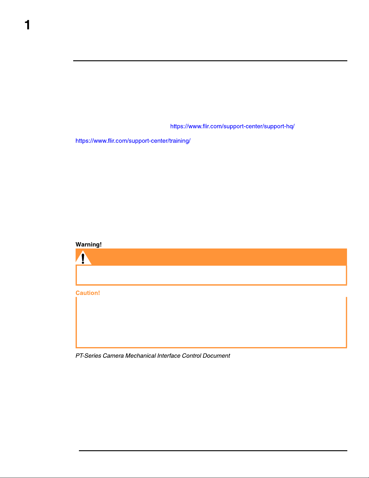
For safety, and to achieve the highest levels of performance from the camera system, follow the
warnings and cautions in this manual when handling and operating the camera system.
If mounting the camera on a pole, tower or any elevated location, use industry standard safe
practices to avoid injuries.
Except as described in this manual, do not open the camera for any reason. Disassembly of the
camera (including removal of the cover) can cause permanent damage and will void the warranty.
Be careful not to leave fingerprints on the camera’s infrared optics.
The camera requires a power supply of 24 Volts nominal. Operating the camera outside of the
specified input voltage range or the specified operating temperature range can cause permanent
damage.
(ICD)
(FLIR Doc # 427-0075-XX-19)—available from the FLIR website, provides further details regarding
mechanical dimensions and mounting for the PT-Series HD camera.
427-0075-01-12 Revision 140 October 2019 4
This document does not contain any export-controlled information.
Page 5
PT-Series HD Camera Installation
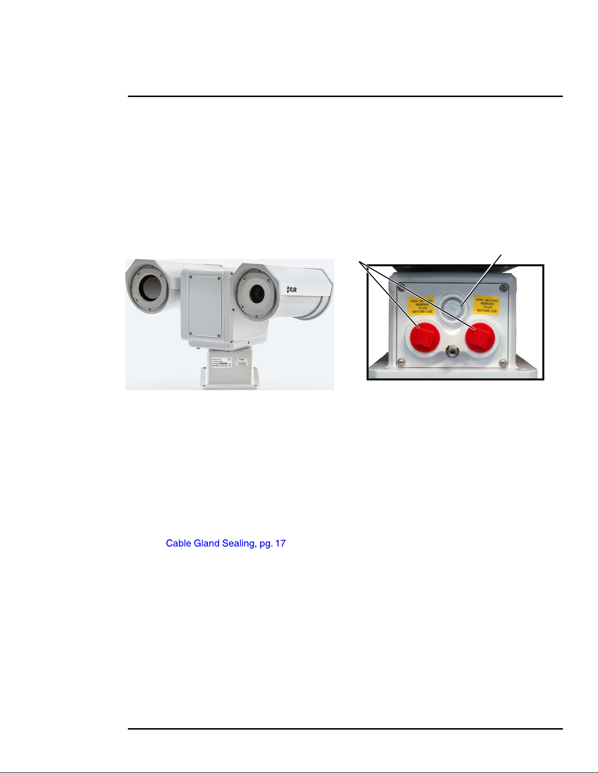
Shipping plugs only -
1.1 Camera Overview
The PT-Series HD camera is both an analog and an IP camera. The video from the camera can be
viewed over a traditional analog video network or it can be viewed by streaming it over an IP network
using MJPEG or H.264 encoding. Analog video will require a connection to a video monitor or an
analog matrix/switch. The IP video will require a connection to an Ethernet network switch and the
appropriate software for viewing the video stream.
1.2 Installation Overview
Remove before installing
Vent
Figure 1-1: PT-Series HD
The PT-Series HD camera is intended to be mounted outdoors on a medium-duty fixed pedestal
mount or wall mount commonly used in the CCTV industry. Cables will exit from the back of the
camera housing. The mount must support up to 45 lbs (20 KG). The camera can be controlled
through either serial or IP communications. The camera operates on 21 Vac to 30 Vac or 21 Vdc to
30 Vdc. In order to access the electrical connections and install the cables, it is necessary to
temporarily remove the back cover of the camera housing. Ensure the back cover is replaced in the
same orientation, with the two cable glands below the central pressure equalization vent.
1.2.1 Camera Connection Options
Camera connections are made through water-tight cable gland seals on the rear of the camera.
Refer to to ensure the glands are used correctly and the connections
are sealed.
Analog video will require at least one connection to a video monitor or an analog video matrix switch.
In most analog installations, two video connections will be used—one for the thermal camera video,
and one for the daylight camera video. The camera provides two BNC connectors for these analog
video channels.
An Ethernet connection is provided for IP video streaming and for command and control
communications using a web browser.
For analog installations that are not using Ethernet/IP, a serial cable (RS232 or RS422) can be
connected and used for command and control communications, supporting either Pelco D or Bosch
protocols. It is recommended an Ethernet cable should also be installed to allow easy remote access
for camera configuration, operation, and troubleshooting.
427-0075-01-12 Revision 140 October 2019 5
This document does not contain any export-controlled information.
Page 6

PT-Series HD Camera Installation
Network Security
The camera supports IEEE 802.1x authentication when connected to a network supporting the
following requirements:
• Network device (Authenticator) such as an Ethernet switch configured with 802.1x
• Authentication server supporting either TLS
Refer to for information on how to configure the LAN settings.
1.2.2 Serial Communications Overview
The installer must decide if the serial communications settings will be configured via hardware (DIP
switch settings) or software (default). If the camera has an Ethernet connection, then generally it is
easier (and more convenient) to make configuration settings via software. Then configuration
changes can be made over the network without physically accessing the camera. Also the settings
can be saved to a file and backed up or restored as needed.
If the camera is configured via hardware, then configuration changes in the future may require
accessing the camera on a tower or pole, dismounting it, and removing the back and so on. If the
camera does not have an Ethernet connection, the DIP switches must be used to set the serial
communication options.
1.2.3 Supplied Components
The PT-Series HD camera ships with these standard components:
• Multi-sensor pan/tilt camera unit
• Galvanic isolation kit (PN 4204960)
• Noise suppression ferrite
• Cable glands and spare parts kit
1.2.4 Required Components
The installer will need to supply the following items; the cable lengths are specific to the installation.
• 24 Vdc or 24 Vac power supply
Note
A single ferrite is supplied with this equipment, the equipment was tested for compliance with the
FCC limits for a Class A digital device using the ferrite installed on the system power cable. When
connecting one or two power cables to the equipment, the supplied ferrite must be installed with this
equipment. A power installation using metal conduit does not require installing the ferrite.
• Electrical cables, for system power and heater power; 3-conductors are required for system
power (one ground) and two conductors are required for heater power (no ground). The wire
gauge must be determined by cable length and supply voltage. A single 5-conductor, shielded
cable or two individual cables may be used. Refer to for additional
information.
• Camera grounding strap
• Coaxial RG59U video cables and a BNC adapter at the camera end for analog video
427-0075-01-12 Revision 140 October 2019 6
This document does not contain any export-controlled information.
Page 7
PT-Series HD Camera Installation
• Shielded CAT6 Ethernet cable for streaming video, control, and for software updates. CAT5e
Ethernet cable may be adequate in many installations except when closely installed with power
cables in demanding video streaming networks.
• Serial cable for serial communications—optional
• Miscellaneous electrical hardware, camera mount (with stainless steel washers and bolts),
connectors, and tools
1.3 Location Considerations
Install the camera in a location that will allow access for regular periodic cleaning (fresh water rinse),
inspection of mounting integrity and mechanical soundness, and preventative maintenance. Ensure
the camera and the camera mount are routinely inspected on a periodic basis.
The camera will require connections for power, communications (IP Ethernet, serial), and video
(analog, IP digital).
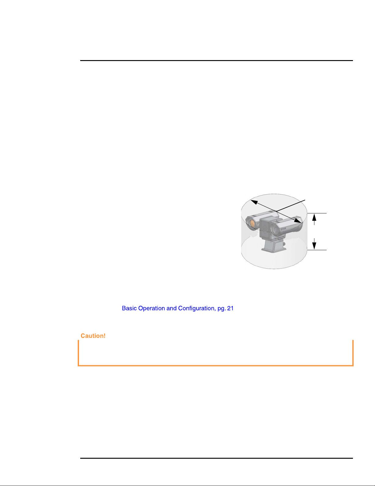
• Ensure the 360° pan and 180° tilt exclusion zone is
free of all obstructions.
Diameter 25.5 in
• Install all cameras with an easily accessible Ethernet
connection to support future software updates.
• Ensure that cable distances do not exceed the
specifications and that cables adhere to all local and
17.4 in
high
industry standards, codes, and best practices.
1.4 Bench Testing
Connect the power, video, serial, and Ethernet
connections and confirm that the video is displayed on a
monitor when the power is turned on. Confirm the camera
can be controlled by moving it (pan/tilt). For configuration
and basic setup information using the onboard web
server, refer to .
Maximum keep-out cylinder
1.5 Camera Mounting
Ensure that the camera base is electrically isolated and properly grounded when it is secured to its
mount. Contact between the stainless steel fasteners and any bare aluminum may cause galvanic
corrosion which will shorten the life of the installation and may void the camera warranty.
Galvanic isolation is critical in preventing corrosion. Proper installation of galvanic isolation pad and
washers is important for long product life.
There are two critical steps related to proper galvanic isolation camera mounting:
• Installation of galvanic isolation kit
• Proper grounding (bonding) to earth ground
1.5.1 Galvanic Isolation
The Galvanic Isolation Kit (FLIR PN 4204960) is for use with all PT-Series HD cameras. The
isolation plate and nylon shoulder or flat washers provide electrical isolation between the stainless
427-0075-01-12 Revision 140 October 2019 7
This document does not contain any export-controlled information.
Page 8
PT-Series HD Camera Installation
steel fasteners and the aluminum camera base, and electrically isolates the complete PT-Series HD
camera from the customer mount. Galvanic isolation is critical in preventing corrosion. Proper
installation of galvanic isolation pad and washers is important for long product life. Refer to
for specific instructions.
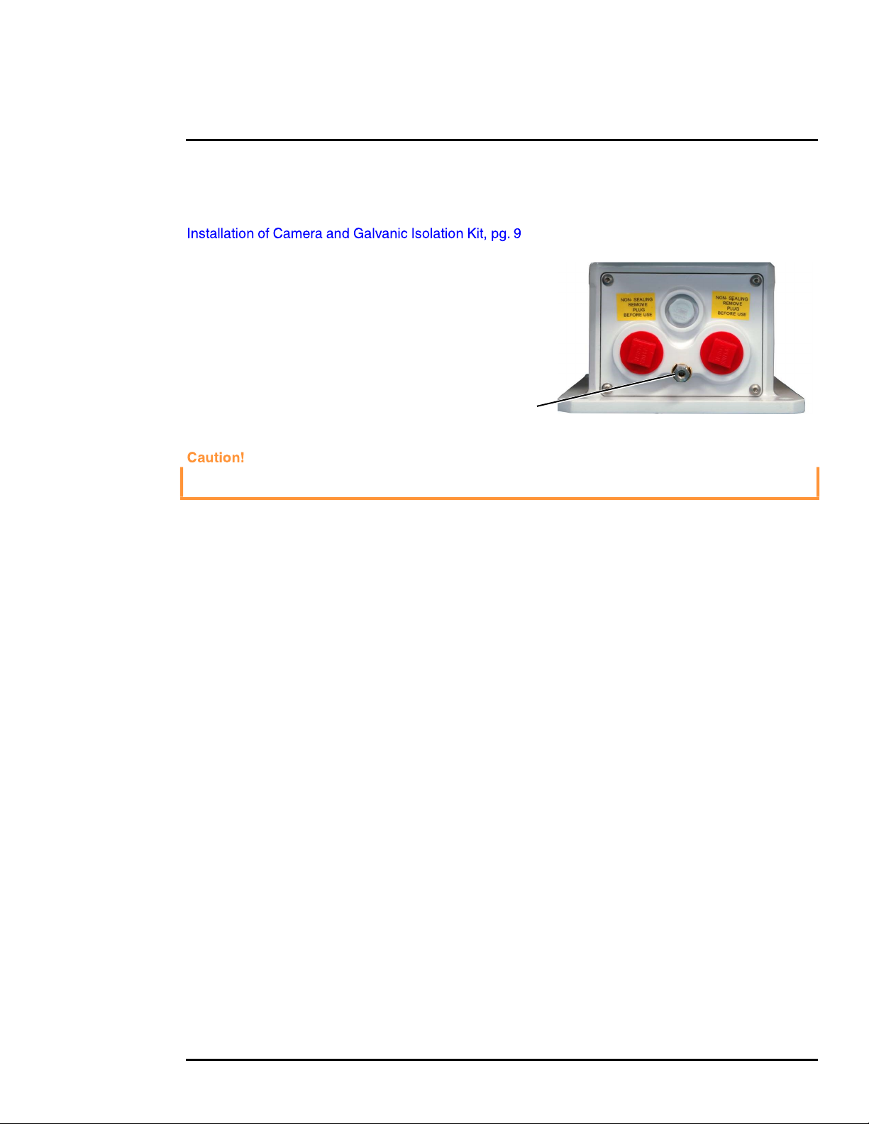
1.5.2 Earth Ground Connection
Earth ground connection is very
important to protect PT-series from
surge induced failures and corrosion
caused by stray current/ground loops.
Attach ground wire (16 AWG or larger)
to ground lug on access panel. Use the
large hex nut to secure ground wire to
stud on access panel. Ground stud is
Ground Lug
#8-32 thread.
When lifting the camera use the camera body and base, not the tubes.
427-0075-01-12 Revision 140 October 2019 8
This document does not contain any export-controlled information.
Page 9
PT-Series HD Camera Installation
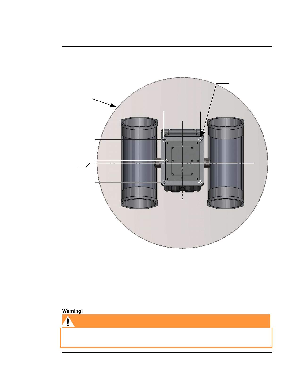
PT-Series HD cameras must be mounted upright on top of the mounting surface, with the base
below the camera. The unit should not be hung upside down.
Not to scale
All dimensions in inches
Pan volume
minimum Ø25.5
2X 3.17 ± .02
0
0.295
2X 3.21 ± .02
2X 2.72 ± .02
4X Ø.354 THRU
2X 2.72 ± .02
0
Tilt Axis
Pan Axis
Figure 1-2: PT-Series HD Camera Mounting
1.5.3 Installation of Camera and Galvanic Isolation Kit
Important Safeguards and Warnings
• Installation and servicing should be done by qualified installation and service personnel only.
• Installation should be done according to all local and national electrical and mechanical codes,
using only approved materials.
Before drilling into walls or ceilings for mounting the camera, verify that areas behind these positions
do not contain electrical or other utility service lines. Serious injury or death may result from failure
to heed this warning.
427-0075-01-12 Revision 140 October 2019 9
This document does not contain any export-controlled information.
Page 10
PT-Series HD Camera Installation
• Once the mounting location has been selected, verify both sides of the mounting surface are
accessible and free of utility service lines or other obstructions.
• Use stainless steel hardware to fasten mounts to outdoor surfaces.
• Use a thread locking compound such as Loctite 242 or equivalent with all metal to metal
threaded connections.
• To prevent damage from water leakage when installing outdoors, apply sealant around the bolt
holes between the mount and the mounting surface.
Following this procedure is critical to maintaining the warranty on your PT-Series HD product.
Failure to follow these instructions can potentially void the camera warranty.
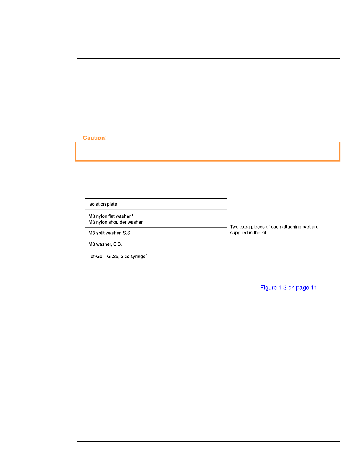
Table 1-1: Kit Contents
Description Qty
1
6
6
6
6
optional
a. Use the alternate nylon flat washers and Tef-Gel lubricant on fasteners for PT-Series HD camera bases
with mounting holes that are too small to accept the shoulder washers. A syringe of Tef-Gel will be supplied
in the mounting kit when the nylon flat washer is required.
Step 1 Determine the correct positioning of the isolation plate (See ).
Step 2 Place the isolation plate and the camera on the mounting structure aligning the bolt holes
or studs.
Step 3 Install nylon shoulder washers (4x) or nylon flat washers (4x) onto camera base.
If using nylon flat washers, apply a generous coat of Tef-Gel filling all gaps and voids.
Step 4 Secure the camera using 5/16” or M8 fasteners (4x) with stainless steel flat washers and
split washers on top of the nylon washers.
427-0075-01-12 Revision 140 October 2019 10
This document does not contain any export-controlled information.
Page 11
PT-Series HD Camera Installation
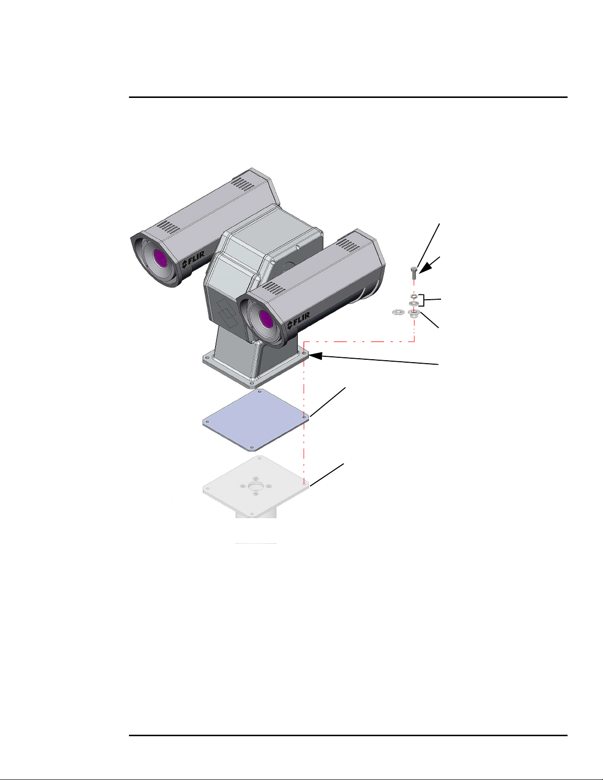
Step 5 Ensure the camera is properly grounded. FLIR requires using a 14 AWG to 16 AWG
grounding strap anchored to the ground lug on the back plate of the camera housing and
then terminated to the nearest earth-grounding point.
M8 or 5/16” fasteners (not supplied)
4 places, minimum length 1 in.
(dependent on mounting structure)
If using nylon flat washers,
apply a generous coat of Tef-Gel
filling all gaps and voids.
(4 places)
M8 split lock washer (4 places)
M8 flat washer (4 places)
M8 nylon shoulder washer or
nylon flat washer (4 places)
If using nylon flat washers,
apply a generous coat of Tef-Gel
isolation plate
example mounting structure
(FLIR PN 500-0461-00)
filling all gaps and voids.
(4 places)
Figure 1-3: PT-Series HD Galvanic Isolation Kit (PN 4204960)
427-0075-01-12 Revision 140 October 2019 11
This document does not contain any export-controlled information.
Page 12
PT-Series HD Camera Installation
Analog Video
IP Network
Analog Visible Video
1.6 Camera Connections
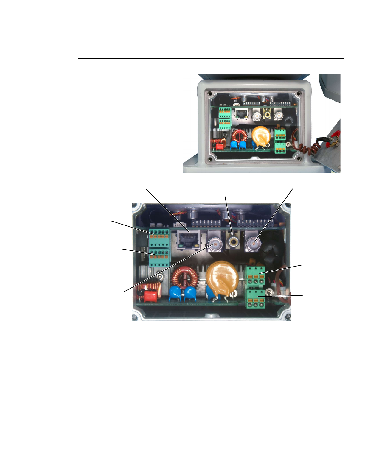
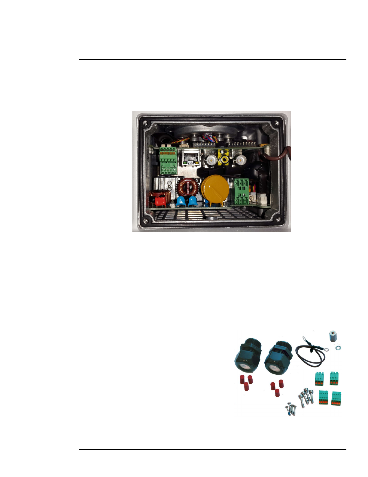
1.6.1 Remove the Back Cover
Use a 2.5 mm hex key to loosen the
captive screws and remove the cover,
exposing the connections at the back
of the camera. There is a grounding
wire connected between the case and
the back cover
(monitoring output only)
Not used
Serial Connector
for local control
Analog Infrared
Video
Camera Power
Heater Power
Figure 1-4: PT-Series HD Camera Connections
427-0075-01-12 Revision 140 October 2019 12
This document does not contain any export-controlled information.
Page 13
PT-Series HD Camera Installation
3/4” NPT for Cable
Gland or Conduit
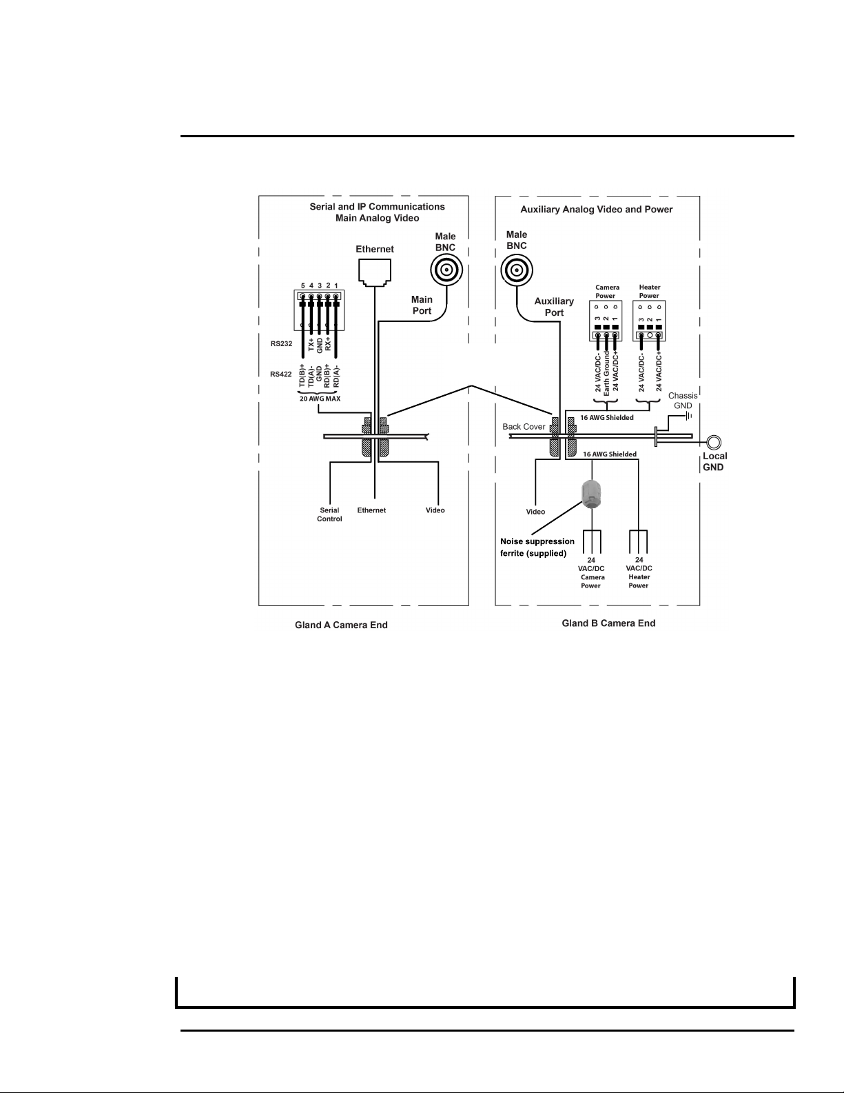
Figure 1-5: PT-Series HD Camera Connection Schematic
1.6.2 Connecting power
The camera itself does not have an on/off switch. Generally a circuit breaker will be used to apply or
remove power to the camera. If power is supplied to it, the camera will be in one of two modes:
Booting Up or Powered On.
The power cables supplied by the installer must use wires that are sufficient size gauge (16 AWG
recommended) for the supply voltage and length of the cable run. Always follow local building codes!
To satisfy FCC requirements, the supplied noise suppression ferrite must be installed on the camera
system power cable unless power cables are enclosed in metal conduit. Refer to Figure 1-4.
Note that the heater power cable requires two-wire power. Do not connect to the power supply
ground.
Ensure the camera is properly grounded. Typical to good grounding practices, the camera chassis
ground should be provided using the lowest resistance path possible. FLIR requires using a
grounding strap anchored to the grounding lug on the back plate of the camera housing and
connected to the nearest earth-grounding point.
Note
The terminal blocks for power connections will accept a maximum 16 AWG wire size.
427-0075-01-12 Revision 140 October 2019 13
This document does not contain any export-controlled information.
Page 14

PT-Series HD Camera Installation
Lens Heaters
The lens heaters are intended to provide lens de-fogging and de-icing in the event of:
• A power interruption which disables the camera for an extended period, and
• Freezing rain which fully covers the lens and obstructs the image.
The PT-Series HD cameras are shipped from the factory with the lens heaters enabled. The lens
heaters are configured to dynamically maintain the camera window at a constant temperature.
The lens heaters may be turned on manually from the Live Video web page (De-Ice button). Refer to
. The heaters, when turned on manually, will run for approximately one
hour unless turned off either by the user (De-Ice button) or the thermostat control.
1.6.3 Video Connections
The analog video connections on the back of the camera are BNC connectors. The camera also
provides an RCA video connector that can be used to temporarily monitor the daylight camera
(DLTV) video output.
The video cables used should be rated as RG59U or better to ensure a quality video signal.
Note
Insert the cable through the cable glands on the enclosure before terminating and connecting them.
In general, the terminated connectors will not fit through the cable gland. If terminated, it is possible
to make a clean and singular cut in the gland seal to install the cable into the gland seal.
1.6.4 Ethernet Connection
The cable gland seal is designed for use with shielded Ethernet cable.
Note
Insert the cable through the cable glands on the enclosure before terminating and connecting them.
In general, the terminated connectors will not fit through the cable gland. If terminated, it is possible
to make a clean and singular cut in the gland seal to install the cable into the gland seal.
1.6.5 Serial Connection
For serial communications, it is necessary to set the parameters such as the signaling standard (RS232 or RS-422), baud rate, number of stop bits, parity and so on. It is also necessary to select the
communication protocol used (either Pelco D or Bosch) and the camera address. By default, the
serial interface uses Pelco D, RS-422 standard, 9600 baud rate, 8/1/none, and address 1.
Note
Typical Bosch systems operate using a biphase connection. FLIR cameras do not accept biphase
signals directly. It may be necessary to install a biphase converter in order to use the Bosch protocol.
Connect the wires of the serial cable as show in . When using the RS-422
standard, ensure the transmit pair of the camera goes to the receive pair of the other device, and
vice versa.
Note
The terminal blocks for serial connections will accept a maximum 20 AWG wire size.
427-0075-01-12 Revision 140 October 2019 14
This document does not contain any export-controlled information.
Page 15
PT-Series HD Camera Installation
Switch
Note
The serial communications parameters for the PT-Series HD camera are set or modified either via
hardware DIP switch settings or via software, through a web browser interface. A single DIP switch
(SW103-9), Software Override determines whether the configuration comes from the hardware DIP
switches or the software settings.
Note
The DIP switches are only used to control serial communications parameters. Other settings, related
to IP camera functions and so on, must be modified via software (using a web browser).
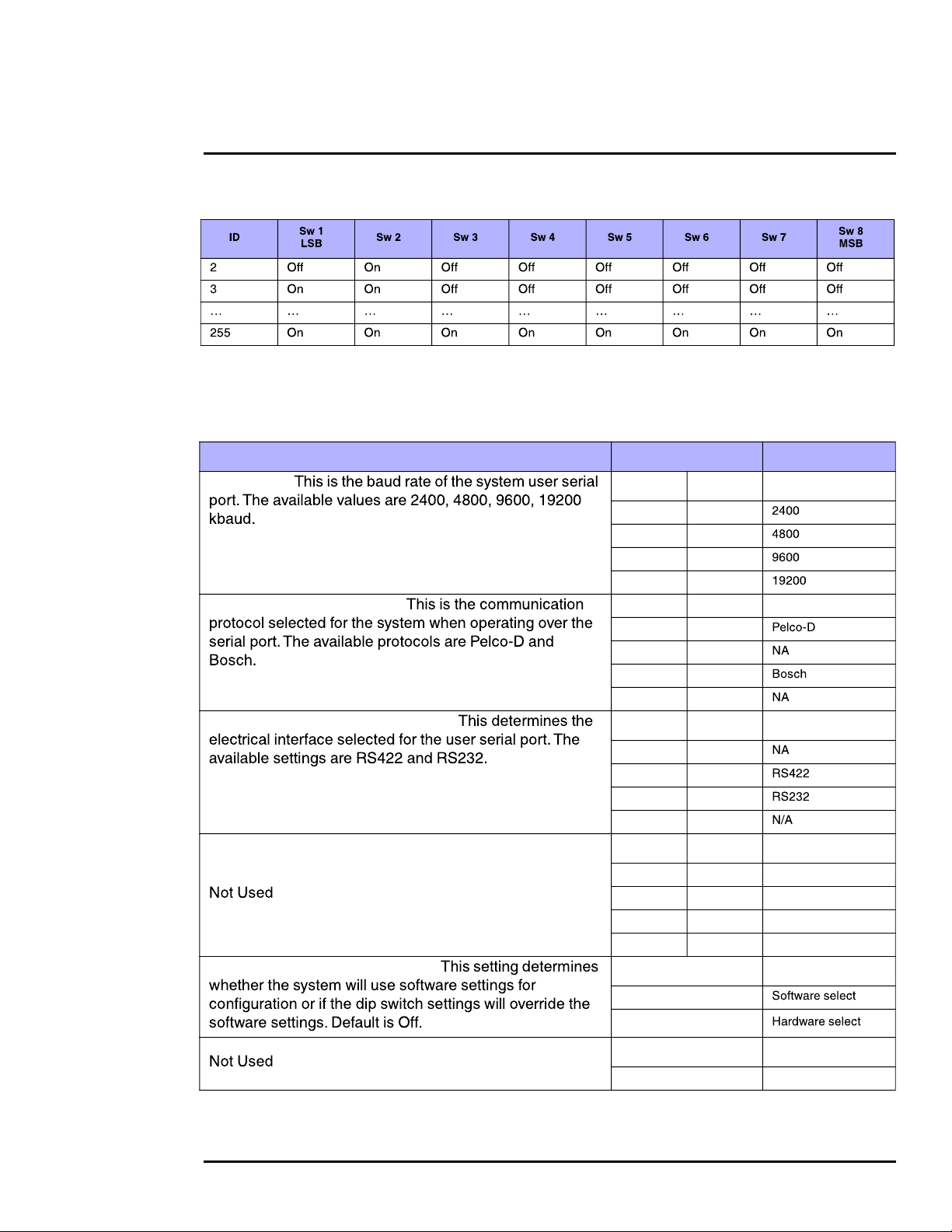
1.6.6 Serial Communications Settings - Hardware DIP Switches
The camera has two blocks of DIP switches that are used to configure the serial communications
settings. One block of switches has 8 switches and is used to set the serial address (or ID) of the
camera. The other block of switches has 10 switches and is used to set baud rate, hardware protocol
(RS-232 or RS-422), serial protocol (Pelco D or Bosch), and Software Override.
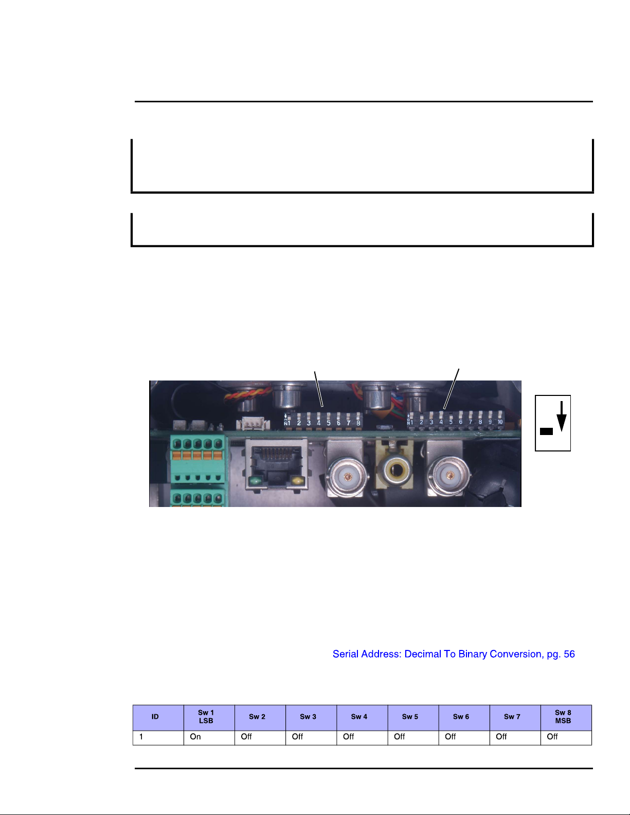
The figure below shows the locations of dip switches SW102 and SW103.
SW102 SW103
Position
Off
On
Figure 1-6: PT-Series HD Serial Communications Configuration
When the Software Override DIP switch is set to the Off position (as it is by default), all of the other
DIP switches will be ignored, and configuration changes must be made through software. If the
switch is set to the On position, all configuration settings related to serial communications are made
with the DIP switches, and changes that are made via software (with a web browser) will be ignored.
Serial Address: Use the block of switches on the left (SW102) to set the serial address of the
camera. The available range of values is from decimal 1 to 255. The dip switches are interpreted as
a binary number, with switch 1 representing the least significant bit (the switches are in the reverse
order of the bits). For convenience, a table of serial addresses and their binary equivalents is
included at the end of the manual. Refer to
Table 1-2: Dip Switch Address/ID Settings—SW101
427-0075-01-12 Revision 140 October 2019 15
This document does not contain any export-controlled information.
Page 16
PT-Series HD Camera Installation
Table 1-2: Dip Switch Address/ID Settings—SW101
Other Serial Communication Parameters: The tables below defines the switch locations, bit
numbering and on/off settings used in controlling the other serial communication parameters.
Table 1-3: Dip Switch Settings—SW103
Settings Description
Baud rate:
Camera Control Protocol:
Serial Communication Standard:
Software Override DIP Switch:
Bit 1 Bit 2
OFF OFF
ON OFF
OFF ON
ON ON
Bit 3 Bit 4
OFF OFF
ON OFF
OFF ON
ON ON
Bit 5 Bit 6
OFF OFF
ON OFF
OFF ON
ON ON
Bit 7 Bit 8
X X
X X
X X
X X
Bit 9
OFF
ON
Bit 10
X
427-0075-01-12 Revision 140 October 2019 16
This document does not contain any export-controlled information.
Page 17
PT-Series HD Camera Installation
1.6.7 Back Cover Gasket
When preparing to re-attach the back cover, make sure that the gasket rests securely in the groove
so that attaching the cover does not cut or otherwise damage the gasket. The picture below shows
the black gasket properly in place.
If possible, lay the camera down to install the gasket and cover. If doing so is not possible, before
installing the cover, apply a small amount of O-ring lubricant to the gasket to help hold it in place.
1.6.8 Cable Gland Sealing
Proper installation of cable sealing glands and use of appropriate elastomer inserts is critical to long
term reliability. Cables enter the camera mount enclosure through liquid-tight compression glands.
Be sure to insert the cables through the cable glands on the enclosure before terminating and
connecting them (the connectors will not fit through the cable gland). Leave the gland nuts loosened
until all cable installation has been completed. Inspect and install gland fittings in the back cover with
suitable leak sealant and tighten to ensure water tight fittings. Teflon tape or pipe sealant (for
example DuPont RectorSeal T™) are suitable for this purpose.
Cable Glands and Spare Parts Kit
The kit contains the two 3/4” cable glands and gland
seal plugs required for non-conduit installations.
The remaining parts included in the kit are:
• a spare ground wire
• a spare ground nut and lock washer
• two spare power terminal block plugs
• two spare serial port terminal block plugs
• four spare F-Series back cover screws
• four spare PT-Series back cover screws
427-0075-01-12 Revision 140 October 2019 17
This document does not contain any export-controlled information.
Page 18
PT-Series HD Camera Installation
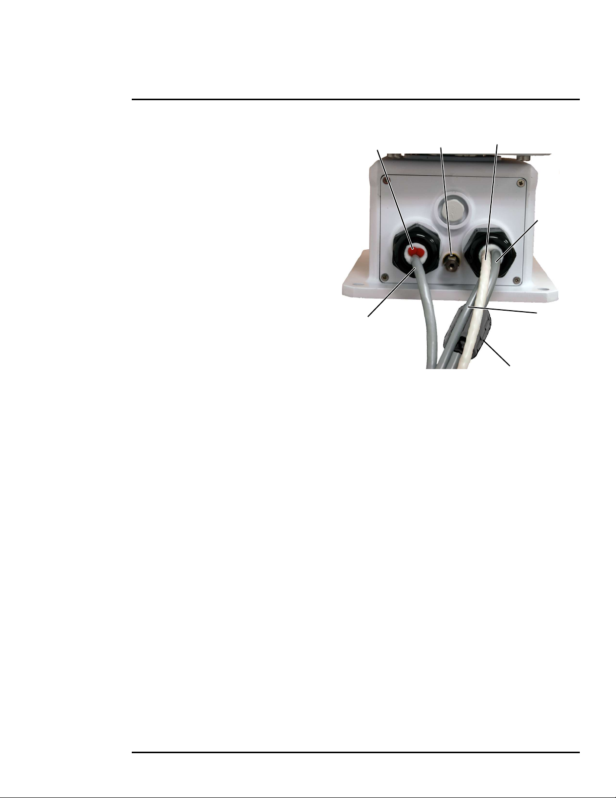
Cable Gland Seal Inserts
Cables may be between 0.23" to 0.29" OD.
Up to six cables may be installed. Plugs are
required for the hole(s) not being used. The
photograph at the right shows two power
cables, an Ethernet cable, an analog video
cable, and two gland seal plugs.
If non-standard cable diameters are used, it
may be necessary to locate or fabricate the
appropriate insert to fit the desired cable.
FLIR Systems, Inc. does not provide cable
gland inserts other than what is supplied with
the system.
Gland seal plugs
Ethernet
Ground
Lug
Analog video
Camera
Power
Heater
Power
Ferrite on camera
power only
427-0075-01-12 Revision 140 October 2019 18
This document does not contain any export-controlled information.
Page 19

PT-Series HD Camera Installation
1.7 PT-Series HD Camera Specifications
Uncooled
Thermal Camera
Model FOV Focal Length
Optical
Characteristics
Visible Camera
Cooled Thermal
Camera
PT-602CZ HD
Compliance and
Certifications
427-0075-01-12 Revision 140 October 2019 19
This document does not contain any export-controlled information.
Page 20

PT-Series HD Camera Installation
Video
System
Integration
Pan/Tilt
General
Environmental
Method 514.6, Procedure 1b
a. Power consumption is independent of the input voltage when the heater is off. The power drawn by the heaters in -
creases with the input voltage to a maximum at 30 Volts.
427-0075-01-12 Revision 140 October 2019 20
This document does not contain any export-controlled information.
Page 21

Basic Operation and Configuration
This chapter provides basic information on how to operate the PT-Series HD camera. A bench test can
be used to verify camera operation before the camera is configured for the local network. This chapter
also provides general configuration information.
2.1 IP Camera, ONVIF Profile S Compliant
When the camera is connected to the network it functions as a server; it provides services such as
camera control, video streaming, network communications, and geo-referencing capabilities. The
communications protocol used is an open, standards-based protocol that allows the server to
communicate with a video management client, such as FLIR Latitude or with a third-party VMS
client, including systems that are compatible with ONVIF Profile S. These clients can be used to
control the camera and stream video during day-to-day operations. Refer to the individual product web
page at for a listing of supported VMS
clients.
2.1.1 Serial and/or IP Communications
For a camera that is installed in a legacy-type CCTV network using analog video, the camera may
commonly be controlled with serial communications. The serial cable from the camera will be
connected to a keyboard/joystick device, or to a video switch, encoder, or DVR that has a serial
communication port. In this case the installer may want to configure parameters such as the address of
the camera, the baud rate, and so on. These parameters can be set through software using a web
browser. The parameters can also be set using DIP switches when IP communications are not used.
2.1.2 Server Configuration
It may be necessary for the installer to make a limited number of configuration changes to the camera
server, such as setting the IP communication parameters, setting new login passwords, as well as
some scene specific parameters. Many of the configuration parameters will remain unchanged from
the factory default settings.
2.2 Camera Bench Test
Since the camera offers both analog video and IP video, the installer should test the camera using the
same type of connections as the final installation. If using analog video and serial communications in
the final installation, also test the IP communications when performing the bench test. If any image
adjustments are necessary, they can be done using a web browser over the IP connection, and saved
as power-on default settings.
When the camera is turned on, the Analog Visible Video temporarily shows the IP address of the
camera web server.
PT-602CZ HD Only—The thermal imager is cooled by a integral Stirling cooler (also known as a
cryocooler) which starts automatically when the camera is powered on. The cryocooler makes an
audible noise when operating, and requires up to 8 minutes to cool the detector down to its operating
temperature. When cooling down, the thermal video image shows a blue screen with the note:
Unit cooling, kindly wait.
Test serial communications by connecting a serial device such as a keyboard and confirm the camera
is responding to serial commands. It may be necessary to configure the serial device interface to
operate with the camera.
427-0075-01-12 Revision 140 October 2019 21
This document does not contain any export-controlled information.
Page 22

Basic Operation and Configuration
Online manual
Select a filter
Once the camera is connected to a network and powered on, set camera network parameters using
the FLIR Discovery Network Assistant (DNA) software, perform a bench test by using a web browser
to view the video and control the camera, or view video in the local Network Video Management
System (for example, FLIR Latitude). The FLIR Discovery Network Assistant (DNA) software does
not require a license to use and is a free download from the individual product web page at:
.
2.2.1 Set IP Address using the FLIR Discovery Network Assistant (DNA)
The PT-Series HD camera is shipped with Dynamic Host Configuration Protocol (DHCP) enabled to
assign IP addresses. Assuming the existing network has a DHCP server, the camera will be
assigned an appropriate IP address. If the network does not have a DHCP server, the PT-Series HD
camera will default to 192.168.0.250. Configuring the camera for IP communications generally
involves the following steps:
Step 1 Connect the Ethernet port of the camera to the existing IP camera network.
Step 2 Connect a PC or laptop to the same network.
Step 3 From the PC connected to the camera network, use the DNA utility to discover and display
the camera’s current IP address.
Click to sort
Right-click
Select IP Setup
427-0075-01-12 Revision 140 October 2019 22
This document does not contain any export-controlled information.
Page 23

Basic Operation and Configuration
Step 4
Step 5 Double-click the camera in DNA’s
Discovery List to open the camera’s web
server Login page in a web browser, or
point a web browser to the camera’s IP
address.
Step 6 Using a web browser, configure the
camera settings, such as camera date/
time, and other parameters, so the
camera is compatible with the existing
network.
2.3 Log into the Camera Web Page
Use a web browser to connect to the camera’s web server using one of three User Names: user,
expert, or admin (the default passwords are user, expert, and admin respectively).
To prevent unauthorized access, change all of the login passwords (admin login required). For
information on how to change the passwords, refer to .
The user login can be used to do the initial bench test of the camera. The expert login may be used
to make configuration changes such as setting the IP address and other server settings. The admin
login has access to all configuration, setup, and maintenance settings.
Two web sessions can be active at once. An inactive session will be logged out after 20 minutes.
Open a web browser — Google Chrome, Mozilla Firefox, Microsoft Internet Explorer 11, or Microsoft
Edge — and enter the camera IP address. The login screen with a picture of the camera will appear.
Enter for the User Name and for the Password, and click Log in.
427-0075-01-12 Revision 140 October 2019 23
This document does not contain any export-controlled information.
Page 24

Basic Operation and Configuration
2.3.1 Live Video Page
The Live Video page displays a live image from the camera on the left part of the screen. Along the
top of the screen are some menu choices, including Live Video (the red text indicates it is selected),
Help and Log out.
On the right side are control buttons and a virtual joystick (for pan/tilt capability).
Toggle Time
Figure 2-1: Live Video Web Page – user login
In the lower right corner of the web page there is a frame rate selector. This selector allows the user
to change the rate at which the frames are displayed in the browser from the default 8 fps up to 16
fps. This controls the frame rate of the user’s own web browser only, and does not affect the video
streams to other users or to an NVR. If the live video is not displayed, refer to
.
Help
The menu displays software version information. If it is necessary to contact FLIR Technical
Support for assistance, it will be helpful to have the information from this page on hand. For
information about the camera including hardware part numbers and serial numbers refer to the
Maintenance > Product Info > Identification web page (requires Admin login).
Log out
Use this button to disconnect from the camera and stop the display of the video stream. If a web
session is inactive for 20 minutes, it will be stopped and it will be necessary to log in again.
Toggle PC/Camera time
Use this button to display either the PC time or the camera time.
427-0075-01-12 Revision 140 October 2019 24
This document does not contain any export-controlled information.
Page 25

Basic Operation and Configuration
2.3.2 Camera Control and Status
In the lower left of the screen are two indicator lights: Control and Status.
Initially the Control light is off, as in the image above, indicating the user is
not able to control the camera immediately. When multiple users are
connected to a camera, only one user at a time can issue commands to the
camera. If another user has control of the camera, the Control light is yellow.
A user is able to request control of the camera by clicking on the yellow or
black light, or simply by sending a command to the camera. After a short
pause, the Control light should turn green. Be patient, there may be a slight
delay between each command while the browser waits for a response from
the camera.
If a command is sent to the camera when the user does not have control, the command will not be
executed, and it is necessary to send the command again once the light is green.
2.3.3 Web Control Panel
The control buttons on the right side of the page can control the camera. When the mouse cursor is
positioned over a button, a tool tip is displayed which explains the function of the button.
When the mouse is positioned over the video window, the video stream source is shown in the upper
left corner of the video image and a snapshot button is shown in the upper right corner of the video
image. The snapshot button will save an image as a .jpg file to the selected destination folder or as
determined by the web browser.
Save snapshot
Video stream
or
This same web interface is used with various FLIR thermal cameras, some of which have different
capabilities. As a result, different buttons in the control panel will appear for different FLIR cameras.
not present for PT-602CZ HD
Go to Preset position.
See Surveillance > Scan List.
Thermal Control Keypad
PT-606Z HD
427-0075-01-12 Revision 140 October 2019 25
This document does not contain any export-controlled information.
Visible Control Keypad
Page 26

Basic Operation and Configuration
The functions of the buttons appearing for the PT-Series HD cameras are described below:
Zoom In/Zoom Out
These buttons zoom the active camera (IR or daylight). On cameras with optical
zoom lenses, digital zoom or E-Zoom extends the ability to zoom in beyond the
optical zoom range, but at the expense of resolution. Also, refer to
.
Toggle Video Source
This button causes the active video source to be switched between the thermal IR
camera and the daylight camera. Refer to
.
Focus Near—IR only—PT-602CZ HD and PT-606Z HD only
This button manually focuses the thermal IR lens closer to the camera. Use it to fine-tune
the focus, if necessary.
Focus Far—IR only—PT-602CZ HD and PT-606Z HD only
This button manually focuses the thermal IR lens further away from the camera. Use it to
fine-tune the focus, if necessary.
Toggle Polarity—IR only
This button changes the way various objects are displayed in the image, for example,
with hot objects displayed as white and cold objects as black, or vice versa.
Toggle Palette—IR only
This button causes the IR camera to cycle through different color palettes. Each of the
palettes presents the IR image using a different color scheme. Use the Toggle Polarity
button to invert the palette, for example, between white hot and black hot.
LowLight Mode On/Off—Visible only
This button enables or disables the mode for improving the video image in low lighting
conditions.
De-Ice On/Off—Configuration dependent
This button manually turns the lens heaters on or off. The heaters, when turned on
manually, will run for approximately one hour unless turned off either by the user (De-Ice
button) or the thermostat control. Refer to .
Freeze Video—Visible only
This button stops the video on a single frame. Click again to start the video.
427-0075-01-12 Revision 140 October 2019 26
This document does not contain any export-controlled information.
Page 27

Basic Operation and Configuration
Autofocus
This button causes the DLTV camera to toggle the autofocus mode. Clicking the button a
second time reinstates the autofocus mode and causes an autofocus operation. This
button causes the IR camera with a zoom lens to perform a one-time autofocus
operation.
Perform IR NUC Calibration—IR only—not present for PT-602CZ HD
This button causes the camera to do a manual Non-Uniformity Correction (NUC)
operation. The PT-Series HD camera, by default, does an automatic NUC calibration as
required based on changes in temperature. The PT-602CZ HD camera (cooled) does not
require a NUC operation.
Pan/Tilt Home
This button causes the camera to go to the Home position. To set a new Home position,
hold the button for approximately 3 seconds.
Electronic Stabilization On/Off—Visible only
This button enables or disables electronic stabilization on the visible video image.
Function—not present for PT-606Z HD
When the Function button is selected, the keypad changes to
a numeric keypad. A tool tip can be shown when a function
has been assigned to a number. Use the back ( ) arrow
to return to the Control Panel.
Go to Preset
The PT-Series HD camera can have a set of predetermined pan/tilt locations, each of
which is known as a preset. For example, a preset may be set for each of the locations
where security surveillance is most needed, a gate, doorway, and other points of access.
When the Go to Preset button is selected, the keypad changes to a
numeric keypad.
To cause the camera to go to a predefined location view (Preset) select a
number.
Use the back ( ) arrow to return to the Control Panel.
2.4 Camera Configuration
The following procedures describe how to do the most common camera configuration steps, such as
setting the camera IP address and hostname and changing the user passwords. To make these
changes, it is necessary to log in using the admin account.
427-0075-01-12 Revision 140 October 2019 27
This document does not contain any export-controlled information.
Page 28

Basic Operation and Configuration
Note
In most installations, the only camera settings needed are available from the Live Video page
(using Scene Presets or Polarity). Use caution when modifying the camera settings described in
this section. Some settings may adversely affect the thermal image over time or may completely
disable the camera or the network interface.
2.4.1 Expert and Admin Accounts
When a user logs in as expert or admin, additional menus,
Setup and Maintenance are available. The Setup menu is used
to make advanced adjustments to the thermal camera, the
daylight camera, and the pan/tilt platform.
The basic camera configuration steps are accessed through the menu,
using the menus on the left side of the page. The , , and
selections are described below ( ). The login has access to the
pages. The admin login provides access to all configuration options. The login passwords
should be changed (admin login required) to prevent unauthorized access.
427-0075-01-12 Revision 140 October 2019 28
This document does not contain any export-controlled information.
Page 29

Basic Operation and Configuration
2.4.2 Setup Menu
The menu is used for GEO Settings, camera setup, and defining parameters for surveillance
zones.
When configuration changes are made with the web browser, the settings are saved to a
configuration file. It is a good idea to make a backup of the existing configuration file prior to making
changes, and another backup once the changes are finalized. If necessary the camera can be
restored to its original factory configuration or one of the saved configurations (refer to
).
It is necessary to have control of the camera to make Setup changes. Changes made through the
menu have an immediate effect (it is not necessary to stop and restart the server). To use
these settings at power up, it is necessary to save the changes.
Adjustments to the IR settings should only be made by someone who has expertise with thermal
cameras and a thorough understanding of how the various settings affect the image. In most
installations, the only camera settings needed are available from the Web Control panel on the Live
Video page (Scene Presets, Polarity, Palettes, and AGC). Haphazard changes can lead to image
problems including a complete loss of video.
Camera Control
Video
By default, two video streams are enabled for each camera: Video 0 and Video 1 are sourced from
the DLTV camera, Video 2 and Video 3 are sourced from the IR thermal imager. All video streams
are available for viewing from a client program such as FLIR Latitude, a stand-alone video player, or
a third-party VMS (including ONVIF systems).
427-0075-01-12 Revision 140 October 2019 29
This document does not contain any export-controlled information.
Page 30

Basic Operation and Configuration
To modify parameters that affect a particular IP Video stream from the camera, select the
appropriate link (for example, ).
The default parameters provide high-quality full frame-rate video streams with reasonable bandwidth
usage. In general, for most installations it will not be necessary to modify the default parameters. In
some cases, such as when a video stream is sent over a wireless network, it may be useful to adjust
the frame rate of the video stream to reduce the required bandwidth.
Select video format
After making adjustments, scroll down to save the changes through power cycles.
427-0075-01-12 Revision 140 October 2019 30
This document does not contain any export-controlled information.
Page 31

Basic Operation and Configuration
The parameters in the Encoding section will have a
significant impact on the quality and bandwidth
requirements of the video stream. In general it is
recommended that the default values are used initially, and
then individual parameters can be modified and tested
incrementally to determine if the bandwidth and quality
requirements are met.
For the video streams, the Codec options are H.264 Main
or MJPEG.
The Bit Rate parameter is only used when the Rate Control
parameter is set to CBR (Constant Bit Rate). With the CBR
setting, the system attempts to keep the video at or near
the target bit rate.
The I-Frame Interval parameter controls the number of P-frames used between I-frames. I-frames
are full frames of video and the P-frames contain the changes that occurred since the last I-frame. A
smaller I-Frame Interval results in higher bandwidth (more full frames sent) and better video quality.
A higher I-Frame Interval number means fewer I-frames are sent and therefore results in possibly
lower bandwidth and possibly lower quality.
The Resolution parameter controls the video resolution and therefore can have a large impact on
bandwidth usage. The higher the resolution, the larger the size of the frame and the higher the
network bandwidth required. Table 2-1 provides the corresponding resolution for each setting.
VIDEO - 0
VIDEO - 1
VIDEO - 2
VIDEO - 3
a. Factory default resolution is shown in bold type.
If the video will be viewed on its own and on a reasonably large screen, a large image size setting
may look better. On the other hand, if the video is shown as a tile in a video wall, a smaller image
size may look as good and consume less bandwidth.
The default RTP Settings for connecting to an IP video
stream from the PT-Series HD are shown in the
illustration. The RTP Port and the Stream Name are used
when establishing a session from a client.
The connection string for each of the video streams are
as follows:
VIDEO 0 - rtsp://192.168.0.250:554/stream1/sensor1
VIDEO 1 - rtsp://192.168.0.250:554/stream2/sensor1
VIDEO 2 - rtsp://192.168.0.250:554/stream1/sensor2
VIDEO 3 - rtsp://192.168.0.250:554/stream2/sensor2
427-0075-01-12 Revision 140 October 2019 31
This document does not contain any export-controlled information.
Page 32

Basic Operation and Configuration
For enhanced security, RTSP authentication can be
enabled.
There are some challenges with streaming video over an
IP network, when compared to applications which are less
time-critical, such as email and web browsing. There are
requirements which must be fulfilled to ensure satisfactory
video quality in professional security environments. There are many parameters and factors related
to network infrastructure, protocols, codecs, and so on that can affect the quality and bit rate of a
video stream when it is established between the camera and a client.
RTSP is originated and received on even port numbers and the associated RTCP communication
uses the next higher odd port number; the default RTSP Port is 554.
IR > AGC ROI
The IR camera adjustments to the region of interest (ROI) determine what portion of the image is
used by the Automatic Gain Control (AGC) algorithm. By default all of the pixels in the image are
considered; in some cases it may provide an improved image if a portion of the image is excluded.
For example, the sky is generally very cold, so if the ROI excludes the sky it may add more contrast
to the rest of the image. A pull-down list offers some convenient options.
When Custom is selected, a handle is
shown in the center of the screen.
Drag the handle to set
the size of the ROI box.
Drag the ROI box over
the portion of the scene
that will control the AGC.
427-0075-01-12 Revision 140 October 2019 32
This document does not contain any export-controlled information.
Page 33

Basic Operation and Configuration
To move the camera:
IR > AGC
The AGC parameters affect how the overall IR video image appears. Using the AGC button on the
Live Video page (refer to ), toggle through five AGC
algorithms. The default algorithms are suitable for most installations, but each selection allows a
combination of further adjustments that may provide a more appealing image, depending on
personal preferences. Be aware that the settings that are optimal at one time may be less optimal a
short time later, since conditions such as weather and time of day affect the image and are
constantly changing.
Experiment with different AGC parameters to find the settings that work best for the particular
installation. Select button at the bottom of the page to keep the settings after a power
cycle or select the button to return the settings to default values.
• Brightness (ITT Mean) setting determines the temperature that is at the middle of the 256
“shades of gray” produced by the AGC. Positive values allow more detail in hotter scenes, while
negative values allow more detail in lower temperature scenes. Range is -4 to 4.
• Contrast (Max Gain) can be used to increase contrast, especially for scenes with little
temperature variation (it may also increase noise due to increased gain). Range is 12 to 24.
• Sharpness (DDE Gain) is used to enhance image details and/or suppress fixed pattern noise.
Positive values increase Sharpness, while negative values soften the image and filter fixed
pattern noise. A setting of 0 is neutral and will not have any effect. Range is -10 to 40.
• AGC Filter determines how quickly a scene will adjust when a hot object appears (or
disappears) within the AGC ROI. If set to a low value, when a hot object enters the ROI, the
AGC will adjust more slowly to the hot object, resulting in a more gradual transition. Range is 1
to 32.
Pan and Tilt
Current camera
coordinates and
pan/tilt mode
enter coordinates,
click Go to
The azimuth and elevation angles are measured in degrees. The elevation angle is measured from
horizontal; negative values are down, positive values are up. The Azimuth angle is measured from
the front of the pan/tilt unit; negative values are counter-clockwise, positive values are clockwise.
427-0075-01-12 Revision 140 October 2019 33
This document does not contain any export-controlled information.
Page 34

Basic Operation and Configuration
To setup Presets:
Set Autoscan parameters:
Surveillance > Scan List
position camera,
select Preset ID
Click Set
Surveillance > Auto Scan
To start Auto Scan:
select width and speed,
then select Start
select speed,
select limits,
click Save
Relative Auto Scan (Surveillance mode) will scan the scene starting with the current position of the
camera. Absolute Auto Scan will scan the scene starting with the zero azimuth position of the
camera. Both can be started and the parameters set in the web page. Absolute Auto Scan can also
be started as an option in the Startup mode when the camera boots. Refer to
.
2.4.3 Maintenance Menu
When a user logs in as , a complete menu is available. The basic camera
configuration steps are accessed through the Maintenance menu, using the Server submenu on
the left side of the page.The LAN Settings, Date and Time, Server Status, and Security Options
selections are described below. Generally with these settings it is necessary to save the changes to
make them effective, but it is not necessary to stop and restart the server.
427-0075-01-12 Revision 140 October 2019 34
This document does not contain any export-controlled information.
Page 35

Basic Operation and Configuration
Server > LAN Settings
The page can be used to set the hostname, default gateway, and IP address for the
camera. Scroll down to see settings for Domain Name System (DNS) server and 802.1x Security.
IP Address
When set to DHCP, if the network does not have a DHCP server, the PT-Series HD camera will
default to an IP address of 192.168.0.250. To set the IP address using DNA, refer to
.
If the IP address of the camera is changed, the PC may no longer be on the same network and
therefore may not be able to access the camera until the IP address on the PC is changed also. For
that reason, it may be preferable to change the IP address after making other configuration changes.
When the LAN settings are changed and the Save button is clicked,
a pop-up message will appear to indicate the network interface
should be restarted. Once all the changes have been made and
saved, click on the Restart Network button at the bottom of the
page.
IEEE 802.1x Security
The IEEE 802.1x standard is designed to enhance the security of local area networks. The standard
provides an authentication framework, allowing a user to be authenticated by a central authority. The
PT-Series HD supports authentication using Transport Layer Security (TLS) protocol.
Notes
The camera must be connected to a switch or other device on the network that supports
IEEE 802.1x.
The camera also supports TLS for communication with clients outside the LAN, such as
web browsers. For information about enabling and configuring TLS for communication
outside the LAN, see .
427-0075-01-12 Revision 140 October 2019 35
This document does not contain any export-controlled information.
Page 36

Basic Operation and Configuration
To configure 802.1x security on the LAN using TLS authentication:
Step 1 On the LAN Settings page, scroll down
to 802.1X Security.
Step 2 Select the Use 802.1x security
checkbox.
Step 3 From the Authentication drop-down
menu, select TLS.
Step 4 In the Identity text box, enter a name to
associate with the camera.
Step 5 If uploading a PKCS #8 certificate file,
use the Browse and Upload buttons to
upload the associated CA Certificate
from the server provided by the network
administrator.
If uploading a PKCS #12 certificate file,
you do not need to upload a CA
Certificate.
Step 6 Use the Browse and Upload buttons to upload the Client Certificate from the server
provided by the network administrator.
Step 7 Using the Browse and Upload buttons, upload the Private Key associated with the
identity. The Private Key Password field can be left blank if a password is not required.
If uploading a PKCS #8 file, the private key must be a valid PKCS #8 file.
If uploading a PKCS #12 file, the private key must be a valid PKCS #12 file.
Certificates and keys must be in PEM format. Common file extensions for TLS files in PEM format
are:
• For certificate and public key files: *.crt, *.cer, *.cert, *.pem
• For private key files: *.key
427-0075-01-12 Revision 140 October 2019 36
This document does not contain any export-controlled information.
Page 37

Basic Operation and Configuration
Server > Services > Date and Time
The date, time, and time zone can be obtained from an NTP server, or can be entered manually. If
the NTP mode is selected, the NTP server information can be entered. The NTP server address can
be entered as a static address or can be obtained via DHCP.
Note
The server must be stopped before date and time settings can be changed.
Set the date and time parameters, then select the Save button at the bottom. After saving the
settings, reboot the system. Refer to .
If the Custom mode is selected, a pop-up window allows the information to be entered manually.
Select
Custom
Set Date
427-0075-01-12 Revision 140 October 2019 37
This document does not contain any export-controlled information.
Page 38

Basic Operation and Configuration
Server > Services > Systems
Use the page to set up a connection to a mail server to send outgoing email
notifications.
If the email server is on a different network, ensure the IP default gateway and DNS servers are
configured in the LAN Settings; refer to . Configure the Msg Systems
page with mail server information and then click Save.
Server > Services > Notification Lists
Use this page to setup multiple email addresses and other notifications that can be sent as a result
of alarms being processed by the Alarm Manager.
427-0075-01-12 Revision 140 October 2019 38
This document does not contain any export-controlled information.
Page 39

Basic Operation and Configuration
Server > Services > TLS Config
The settings on this page enable secure, encrypted communication between clients and the camera;
for example, when your web browser accesses the camera’s web interface.
Note
The camera also supports TLS authentication over the camera’s LAN. For information
about configuring TLS authentication for LAN communication, see
.
By default, TLS is disabled. Before enabling it, you need to generate or upload a valid certificate.
You can:
• Use the camera web interface to generate a self-signed certificate.
• Upload a self-signed certificate and a private key.
• Upload a certificate signed by a third-party, a public key, and a private key.
Certificates and keys must be in PEM format. Common file extensions for TLS files in PEM format
are:
For certificate and public key files: *.crt, *.cer, *.cert, *.pem
For private key files: *.key
From the TLS Config page, you can also download certificates and keys previously uploaded to or
generated by the camera. If the certificate saved on the camera is self-signed, you can download the
private and public key files. If the certificate was signed by a third-party CA, you can download the
CA Certificate and the private and public key files.
427-0075-01-12 Revision 140 October 2019 39
This document does not contain any export-controlled information.
Page 40

Basic Operation and Configuration
To generate and install a self-signed certificate:
Step 1 Under Generate Certificate, for Method, select Self-Signed.
Step 1 Enter information such as country code, city name, and organization name.
Step 2 Scroll to the bottom of the page and click Generate Certificate.
Step 3 Allow 15 seconds for the camera to generate the certificate, at which point a confirmation
appears.
To upload a self-signed or third-party CA signed certificate:
Step 1 For Method, select Upload
Certificates.
Step 2 If you are uploading a self-signed
certificate, under Upload Certificate,
browse for and upload the public key
file. Then, under Private Key, browse
for and upload the private key file.
If you are uploading a third-party CA
signed certificate, under Upload
Certificate, browse for and upload the
public key file. Under CA Certificate,
browse for and upload the CA
certificate file. Under Private Key,
browse for and upload the private key
file.
Step 3 Verify that the camera certificate files are valid. Make sure Certificates are OK appears
under Method.
427-0075-01-12 Revision 140 October 2019 40
This document does not contain any export-controlled information.
Page 41

Basic Operation and Configuration
Certificate information appears at the bottom of the TLS Config page, under Certificate
Information:
To enable and configure TLS:
Step 1 Under TLS Configuration, for Enabled, select
Yes.
Step 2 Select whether to redirect HTTP requests to
HTTPS.
Step 3 Click Save.
Step 4 Click Reboot. The camera reboots. After the camera reboots, TLS is enabled.
Server > Server Status
The page provides an indication of the current server status (either running or
stopped) and buttons for starting or stopping the server and for rebooting the system. The Uptime
section of the Server Status page shows how long the camera has been running, number of users,
and the load on the camera processor. All values are updated only when the Server Status page is
first accessed.
427-0075-01-12 Revision 140 October 2019 41
This document does not contain any export-controlled information.
Page 42

Basic Operation and Configuration
After making configuration changes, it is necessary to save the changes to the server (there is a
Save button at the bottom of each configuration page). The configuration changes do not take effect
immediately. Generally, it is also necessary to stop and restart the server for the changes to become
effective. The server has a configuration that is active and running, and another configuration that is
saved (and possibly different than the running configuration).
The message at the bottom of the page indicates the
saved configuration is different than the active (running)
configuration, and it is necessary to restart the server.
It may take up to 20 seconds or more to stop the server, especially when there are multiple video
streams open. Be patient when stopping the server.
When the server is stopped and the page is refreshed, the status will
show Server Stopped and the Start button will be enabled.
Click on the Start button to restart the server, and when the page
refreshes, the status will again show Server Running. The Start button will
be replaced by a Stop button when the startup procedure has completed.
Note
Server > Security Options
Use the page to enhance the camera’s security by:
• Restricting access through the camera web server to specific IP addresses
• Setting or changing passwords
• Enabling the camera’s firewall and enabling or disabling specific services and their ports
• Enabling Nexus CGI digest authentication
427-0075-01-12 Revision 140 October 2019 42
This document does not contain any export-controlled information.
Page 43

Basic Operation and Configuration
Restrict web configuration
Add IP
address
The admin login can limit which computers have access to the web browser interface. Simply add a
computer’s IP address and click Add. After all the allowed IP addresses are entered, click Save to
save the changes.
Password management
To maintain security of the system, set new passwords for all of the login accounts.
• —Used for ONVIF communication.
• —The user account can only use the page and controls.
• —The expert account can use the page, the camera page, the Server
pages on the menu, and set the password for the expert login.
• —The admin account can use all pages and set all passwords.
Select login
Click Edit
Enter new password
Confirm password
Click Save
Note
427-0075-01-12 Revision 140 October 2019 43
This document does not contain any export-controlled information.
Page 44

Basic Operation and Configuration
Firewall settings
For enhanced security, a firewall can be enabled (by scrolling down on the Security Options page).
With the firewall enabled, you can open the following services and their default ports by selecting
Enabled:
• RTSP
• SSH
• uPnP Discovery
• Nexus SDK
• TRK Interface
Select
Yes
Important Note
Nexus CGI digest authentication
Below the firewall settings, you can enable Nexus CGI digest authentication.
Select
Digest
427-0075-01-12 Revision 140 October 2019 44
This document does not contain any export-controlled information.
Page 45

Basic Operation and Configuration
Sensor > Communications > Serial Remote
Bosch
settings
Pelco-D
settings
Select
protocol
Save
Toggle Server (Stop/Start)
Sensor > Communications > VMS Remote
The VMS Remote page provides communication interfaces for devices that connect to the camera.
Authentication when enabled uses the same passwords set from the Server Security Options
page. Refer to .
For ONVIF,
use the settings
in Interface 1
Scroll down
For Nexus CGI,
use the settings
in Interface 0
Nexus CGI Interface
After the interface is configured, scroll down and click on the Save button to save the configuration.
The changes will not take effect until the server is stopped and started.
427-0075-01-12 Revision 140 October 2019 45
This document does not contain any export-controlled information.
Page 46

Basic Operation and Configuration
ONVIF Interface
The ONVIF (Open Network Video Interface Forum) is an open industry forum for the development of
a global standard for the interface of network video products. An ONVIF-compliant VMS can be used
to control a FLIR camera. Refer to the VMS documentation to determine what parameters are
needed. By default, the camera is configured with a VMS Remote interface with ONVIF 2.0
parameters (Profile S). After the interface is configured, scroll down and click on the Save button to
save the configuration. The changes will not take effect until the server is stopped and started.
Several types of third-party Video Management Systems (VMS) are supported by FLIR IP cameras.
Because these systems tend to evolve and change over time, contact the local FLIR representative
or FLIR Technical Support to resolve any difficulties or questions about using this feature.
Sensor > Devices > IR > Zoom Slave
The Zoom Slave function is set from the IR web page. To slave the IR camera to the DLTV zoom
select the IR web page and scroll down to Zoom Slave.
Set to Yes
Select zoom mode
Select camera
controlling zoom
Scroll down
to Save
When the IR camera zoom is slaved to the DLTV camera (Specific Camera), the cameras will only
zoom when the DLTV camera is the active camera.
427-0075-01-12 Revision 140 October 2019 46
This document does not contain any export-controlled information.
Page 47

Basic Operation and Configuration
Sensor > Devices > Pan & Tilt
Scroll down to select an action the camera will perform at startup (power cycle or server reset).
Scroll down
to Save
Select an action
from the menu
Sensor > Modules > Video
By default, four video streams are enabled for the camera: Video 0, Video 1, Video 2, and Video 3.
The streams are available for viewing from a client program such as FLIR Latitude, a stand-alone
video player, or a third-party VMS including ONVIF systems. By default, Video 0 and Video 1 are
from the visible camera, while Video 2 and Video 3 are from the IR sensor.
Adjustments to these settings should only be made by someone trained with thermal cameras
and a thorough understanding of how the various settings affect the image.
Haphazard changes can lead to image problems including a complete loss of video.
427-0075-01-12 Revision 140 October 2019 47
This document does not contain any export-controlled information.
Page 48

Basic Operation and Configuration
To modify parameters that affect a particular IP Video stream from the camera, select the
appropriate link at the top of the page (for example, ).
The default RTP Settings for connecting to an IP video stream
from the PT-Series HD are shown in the illustration. The RTP
Port and the Stream Name are used when establishing a
session from a client.
Given the camera IP address of 192.168.0.250, the complete
connection string for each of the video streams are as follows:
VIDEO 0 - rtsp://192.168.0.250:554/stream1/sensor1
VIDEO 1 - rtsp://192.168.0.250:554/stream2/sensor1
VIDEO 2 - rtsp://192.168.0.250:554/stream1/sensor2
VIDEO 3 - rtsp://192.168.0.250:554/stream2/sensor2
In addition, to maintain compatibility with legacy systems the
stream names are aliased as: ch0 = stream1/sensor1,
ch1 = stream2/sensor1, ch2 = stream1/sensor2, and ch3 = stream2/sensor2.
The video streams can be accessed with the shortened strings, such as rtsp://192.168.0.250/ch0.
In some networks, the RTP/RTSP traffic is carried (tunneled) over Hypertext Transfer Protocol
(HTTP) as that may allow the traffic to cross network boundaries and firewalls. While this method
involves more overhead due to encapsulation, it may be necessary for clients to access the video
streams when HTTP proxies are used.
By default, the video streams from the camera are sent
using multicast packets. With Multicast enabled, video
packets are shared by streaming clients, so additional
clients do not cause bandwidth to increase as dramatically.
If more than one camera is providing multicast streams on
the network, be sure to configure each stream with a unique
multicast Destination Network IP address and Destination
Port combination.
427-0075-01-12 Revision 140 October 2019 48
This document does not contain any export-controlled information.
Page 49

Basic Operation and Configuration
The time-to-live field controls the ability of IP packets to traverse network boundaries. A value of 1
restricts the stream to the same subnet. Greater values allow increasing access between networks.
The video streaming is done using a protocol generally referred to as Real-time Transport Protocol
(RTP), but there are actually many protocols involved, including Real-Time Transport Control
Protocol (RTCP) and Real Time Streaming Protocol (RTSP). In the background, a “negotiation”
takes place to establish a session between the client (such as FLIR Latitude, a third party VMS, or
video player) and the camera. The ports which form a session are negotiated using a protocol such
as RTSP. A client typically requests a video stream using its preferred settings, and the camera can
respond with its preferred settings. As a result, many of the details are established dynamically,
which may run contrary to network security requirements.
The parameters in the Stream Settings section will have a
significant impact on the quality and bandwidth requirements
of the video stream. In general it is recommended that the
default values be used initially, and then individual
parameters can be modified and tested incrementally to
determine if the bandwidth and quality requirements are
met.
For video streams, the Codec options are H.264 and
MJPEG.
The Frame Rate parameter controls the number of frames
per second in the video stream.
The I-Frame Interval parameter controls the number of P-frames used between I-frames. I-frames
are full frames of video and the P-frames contain the changes that occurred since the last I-frame. A
smaller I-Frame Interval results in higher bandwidth (more full frames sent) and better video quality.
A higher I-Frame Interval number means fewer I-frames are sent and therefore results in lower
bandwidth and possibly lower quality.
When the Rate Control Type parameter is set to VBR (Variable Bit Rate), the Bit Rate parameter is
used as an upper limit bit rate and the system keeps the stream at or under the target bit rate. When
the Rate Control Type parameter is set to CBR (Constant Bit Rate), the Bit Rate parameter is used
as a target bit rate. The system attempts to keep the bit rate of the video at or near the target.
427-0075-01-12 Revision 140 October 2019 49
This document does not contain any export-controlled information.
Page 50

Basic Operation and Configuration
2.4.4 Files Menu
The administrative actions for accessing, updating, and transferring files are accessed through the
menu on the left side of the page. Selected actions from the Firmware, , and
Log pages are described below.
Stop server
Files > Firmware
For camera firmware updates, manually install a firmware update file by first stopping the camera
server, browsing to select the update file on your computer, and selecting Upload. The firmware files
will be uploaded and installed.
Files > Configuration
The Configuration page allows the Nexus Server configuration to be displayed or backed up locally
(on the camera). The configuration file can also be downloaded to another computer for backup, or a
new configuration file can be uploaded from a computer to the camera. Shown at the top of the page
427-0075-01-12 Revision 140 October 2019 50
This document does not contain any export-controlled information.
Page 51

Basic Operation and Configuration
is the configuration script file in a scrollable window. This can be useful if help is ever needed from a
support engineer.
In the Backup & Recovery section, click the Restore link associated with the factory.defaults
configuration to restore the camera to its factory settings. This file can not be modified or deleted, so
it is always available.
Use the Backup button to make a backup of the final settings. This will make a backup copy of the
configuration file and store it locally on the camera.
In the Upload & Download section, the Download Configuration File link can be used to save a copy
to a PC for safe keeping. A pop-up window will ask for a file name and destination folder.
The Upload button is used to transfer a configuration file from a PC to the camera.
Note
427-0075-01-12 Revision 140 October 2019 51
This document does not contain any export-controlled information.
Page 52

Basic Operation and Configuration
Files > Log > Field Support Log
Scroll down and select the button under Field Support Log to download a zip file to the
computer for field service evaluation.
2.5 Thermal Imaging Overview
PT-602CZ HD Only—When power is applied to the PT-602CZ HD camera, a compact integral
Stirling cooler (also known as a cryocooler) starts automatically. The cryocooler makes an audible
noise when it is operating, and requires up to 8 minutes to cool the thermal imager down to its
operating temperature. When cooling down, the thermal video image shows a blue screen with the
note:
Unit cooling, kindly wait.
The thermal camera makes an image based on temperature differences. In the thermal image, by
default the hottest item in the scene appears as white and the coldest item is black, and all other
items are represented as a gray scale value between white and black.
It may take some time to get used to the thermal imagery from the camera, especially for someone
who only has experience with normal daylight cameras. Having a basic understanding of the
differences between thermal and daylight cameras can help with getting the best performance from
the thermal camera.
Both thermal and daylight cameras have detectors (pixels) that detect energy. One difference
between thermal and daylight cameras has to do with where the energy comes from to create an
image. When viewing an image with an ordinary camera, there has to be some source of visible light
(something hot, such as the sun or lights) that reflects off the objects in the scene to the camera. The
same is true with human eyesight; the vast majority of what people see is based on reflected light
energy.
427-0075-01-12 Revision 140 October 2019 52
This document does not contain any export-controlled information.
Page 53

Basic Operation and Configuration
On the other hand, the thermal camera detects energy that
is directly radiated from objects in the scene. Most objects
in typical surroundings are not hot enough to radiate visible
light, but they easily radiate the type of infrared energy that
the thermal camera can detect. Even very cold objects, like
ice and snow, radiate this type of energy.
The camera is capable of sensing very small temperature
differences, and produces a video image that typically has
dramatic contrast in comparison to daylight cameras. This
high contrast level from the thermal video enables intelligent
video analytic software to perform more reliably.
The performance of the camera varies throughout the day. Right after sunset, objects warmed by the
sun will appear warmest. Early in the morning, many of these objects will appear cooler than their
surroundings, so be sure to look for subtle differences in the scene, as opposed to just hot targets.
While the imagery on the monitor may at first look similar to ordinary black and white daylight video,
experience with the camera in varying conditions and seasons will lead to an appreciation of the
characteristics that make thermal imaging distinct. A few tips on how to interpret some of the
imagery may help to make the most of the system.
The camera senses small differences in apparent radiation from the objects in view, and displays
them as either white (or lighter shades of gray) for warmer objects, and black (or darker shades of
gray) for colder objects. This is why hot objects such as parts on an engines and exhaust pipes
appear white, while the sky, puddles of water and other cold objects appear dark (or cool). Scenes
with familiar objects will be easy to interpret with some experience. The camera automatically
optimizes the image to provide the best contrast in most conditions.
2.6 Troubleshooting Tips
If help is needed during the installation process, contact your local FLIR representative. FLIR
Systems, Inc. offers a selection of training courses to help get the best performance and value from
your thermal imaging camera.
Find out more at the FLIR training web page: .
No video: Check the video connection at the camera and at the display. If the connectors appear to
be properly connected but the camera still does not produce an image, ensure that power has been
properly applied to the camera and the circuit breaker is set properly. If a fuse was used, be sure the
fuse is not blown. If the video cabling is suspected as a possible source of the problem, plug a
monitor into the RCA connection inside the camera and determine if it produces an image.
If the camera still does not produce an image, contact the FLIR dealer or reseller who provided the
camera, or contact FLIR directly (contact information is provided on the rear cover of this manual).
Performance varies with time of day: It may be possible to observe differences in the way the
camera performs at different times of the day, due to the diurnal cycle of the sun. Recall that the
camera produces an image based on temperature differences.
At certain times of the day, such as just before dawn, the objects in the image scene may all be
roughly the same temperature, compared to other times of the day. Compare this to imagery right
after sunset, when objects in the image may be radiating heat energy that has been absorbed during
427-0075-01-12 Revision 140 October 2019 53
This document does not contain any export-controlled information.
Page 54

Basic Operation and Configuration
the day due to solar loading. Greater temperature differences in the scene generally will allow the
camera to produce higher-contrast imagery.
Performance may also be affected when objects in the scene are wet rather than dry, such as on a
foggy day or in the early morning when everything may be coated with dew. Under these conditions,
it may be difficult for the camera to show the temperature the object itself, rather than of the water
coating.
Unable To Communicate Over Ethernet: First check to ensure the physical connections are intact
and that the camera is powered on and providing analog video to the monitor. When the camera is
turned on, confirm the camera IP address is shown on the Analog Visible Video monitor after
approximately 90 seconds.
Confirm that the IP address for the PC is on the same network as the camera.
By default the camera will broadcast a discovery packet two times per second. Use the FLIR
Discovery Network Assistant (DNA) a packet sniffer utility such as Wireshark and confirm the
packets are being received by the PC from the camera.
Determine if Windows Personal Firewall is blocking the packets. Turn off the firewall or add an
exception for the client program. Typically when a program runs for the first time, a pop-up
notification may ask for permission to communicate on the network. Select the check boxes
(domain/private/public) that are appropriate for the network.
Unable to View Video Stream: If the video stream from the camera is not displayed in a client
program, it could be that the packets are blocked by the firewall, or there could be a conflict with
video codecs that are installed for other video programs.
When displaying video with FLIR Latitude or a VMS for the first time, the Windows Personal Firewall
may ask for permission to allow the video player to communicate on the network. Select the check
boxes (domain/private/public) that are appropriate for the network.
If necessary, test to make sure the video from the camera can be viewed by a generic video player
such as VLC media player ( ). To view the video stream, specify RTSP
port 554 and the appropriate stream name. For example:
rtsp://192.168.0.250:554/stream1/sensor2.
In addition, to maintain compatibility with legacy systems the stream names are aliased as:
ch0 = stream1/sensor1, ch1 = stream2/sensor1, ch2 = stream1/sensor2, and ch3 = stream2/
sensor2.
The video streams can be accessed with the shortened strings, such as rtsp://192.168.0.250/ch0.
Refer to .
Noisy image: A noisy image is usually attributed to a cable problem (too long or inferior quality) or
the cable is picking up electromagnetic interference (EMI) from another device. Although coax cable
has built-in losses, the longer the cable, or the smaller the wire gauge, the more severe the losses
become; and the higher the signal frequency, the more pronounced the losses. Unfortunately this is
one of the most common and unnecessary problems that plagues video systems in general.
Cable characteristics are determined by a number of factors (core material, dielectric material and
shield construction, among others) and must be carefully matched to the specific application.
Moreover, the transmission characteristics of the cable will be influenced by the physical
environment through which the cable is run and the method of installation.
427-0075-01-12 Revision 140 October 2019 54
This document does not contain any export-controlled information.
Page 55

Basic Operation and Configuration
Check cable connector terminations. Inferior quality connections may use multiple adapters which
can cause unacceptable noise. Use a high-quality video distribution amplifier when splitting the
signal to multiple monitors.
Image too dark or too light: By default the PT-Series HD thermal camera uses an Automatic Gain
Control (AGC) setting that has proven to be superior for most applications, and the camera will
respond to varying conditions automatically. The installer should keep in mind that the sky is quite
cold and can strongly affect the overall image. It may be possible to avoid a problem by slightly
moving the camera up or down to include (or exclude) items with hot or cold temperatures that
influence the overall image. For example, a very cold background (such as the sky) could cause the
camera to use a wider temperature range than appropriate.
Eastern or Western Exposure: Once installed, the camera may point directly east or west, and
this may cause the sun to be in the field of view during certain portions of the day. We do not
recommend intentionally viewing the sun, but looking at the sun will not permanently damage the
sensor. The thermal imaging camera often provides a considerable advantage over a visible camera
in a back-lit situation. However, the sun may introduce image artifacts that eventually will be
corrected but it may take some time to recover. The amount of time needed will depend on how long
the camera was exposed to the sun. The longer the exposure, the longer the recovery time needed.
Figure 2-2: Images facing sun
thermal cameravisible camera
427-0075-01-12 Revision 140 October 2019 55
This document does not contain any export-controlled information.
Page 56

Serial Address: Decimal To Binary
Conversion
Note, the order of the switches 1-8 is the reverse of the binary digits. For example, for address 1 the
binary equivalent is 00000001 and the left-most switch (switch1) is on.
3.1 Address Conversion Table
Address Sw1 Sw 2 Sw 3 Sw4 Sw 5 Sw 6 Sw 7 Sw 8
1 ON OFF OFF OFF OFF OFF OFF OFF
2 OFF ON OFF OFF OFF OFF OFF OFF
3 ON ON OFF OFF OFF OFF OFF OFF
… … … … … … … … …
255 ON ON ON ON ON ON ON ON
The following table shows the binary equivalent for each decimal address between 1 and 255.
427-0075-01-12 Revision 140 October 2019 56
This document does not contain any export-controlled information.
Page 57

Serial Address: Decimal To Binary Conversion
427-0075-01-12 Revision 140 October 2019 57
This document does not contain any export-controlled information.
Page 58

FLIR Systems, Inc.
6769 Hollister Ave
Goleta, CA 93117
USA
Corporate Headquarters
FLIR Systems, Inc.
27700 SW Parkway Ave.
Wilsonville, OR 97070
USA
Support:
Document:
427-0075-01-12
Revision: 140
Date: October 2019
This document does not contain any export-controlled information.
 Loading...