

Flir 427-0064-80-00, 427-0064-90-00, 427-1064-11-00, 427-1064-21-00, 427-0064-51-00S User Manual
...Page 1
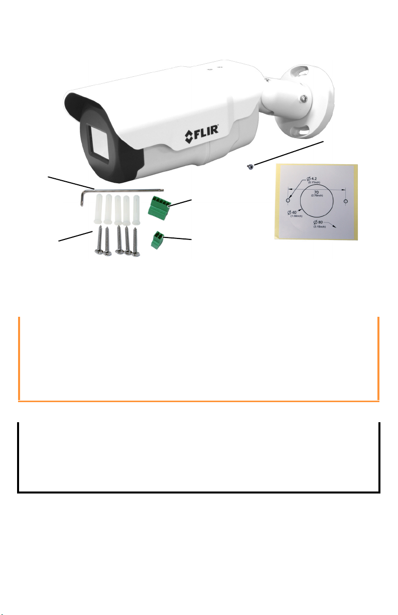
FB-Series Camera
Items Included in Kit
Screws
Mounting
Power
template
plug
and anchors
Alarm
plug
To r x
wrench
Tor x sc r ew
(spare)
Quick Connect Guide
Caution!
Do not disassemble the FB-Series camera. Damage to the camera can occur
as the result of careless handling or electrostatic discharge (ESD).
Before installing the FB-Series camera you should read and understand the
following documents which provide details regarding mechanical dimensions
and installation safety.
• FLIR FB-Series Installation Manual (427-0064-00-12)
Power: Power Over Ethernet (PoE) or 12 Vdc or 24 Vac
Power terminal plug: wire size from 16 AWG to 20 AWG
Analog Video Cable: BNC-terminated RG-59/U solid-center coax cable
Ethernet Cable: Cat5e or Cat6
I/O terminal plug: not supported
FLIR Systems, Inc.
6769 Hollister Avenue
Goleta, CA 93117
USA
Support: http://www.flir.com/security/display/?id=71083
427-0064-00-28 Rev 100 August 2017
Corporate Headquarters
27700 SW Parkway Ave.
Wilsonville, OR 97070
USA
Page 2
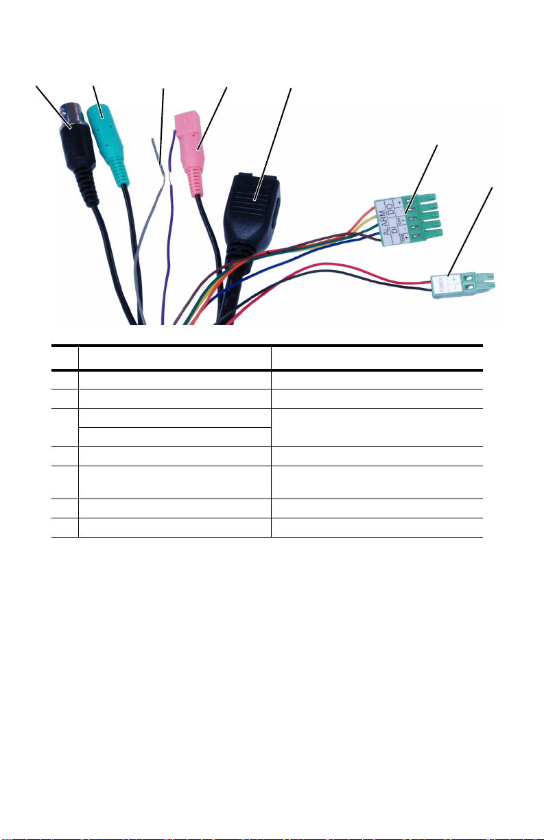
Figure 1-1: Camera Connections
1
7
6
5234
Connection Purpose
1BNC Analog video
2 Green barrel not supported
3
Purple D-
not supported
Grey D+
4 Pink barrel not supported
5Ethernet
PoE power, communications, IP video
stream
6 5-pin plug not supported
7 2-pin plug Vac or Vdc power
427-0064-00-28 Rev 100 August 2017
Page 3
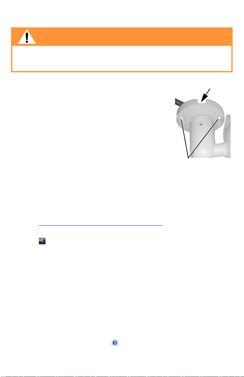
Step 1 Mount came ra.
M4 mounting
slots
Slot for surface
mounting cable
Warning!
Before drilling into walls or ceilings for mounting the camera, verify that areas
behind these positions do not contain electrical or other utility service lines.
Serious injury or death may result from failure to heed this warning.
a.To install the camera, place the supplied sticky
back template in position.
b.Drill a cable entry hole in the center of template or
use the slot for surface mounting the cables.
c.Drill holes slightly smaller than the supplied
plastic screw anchor on each marked screw hole.
d.Insert the plastic screw anchors into the holes.
e.Connect the camera cables. Refer to Camera
Connections for connecting cables.
f. Cable connections are not waterproof. Seal all
exposed connections.
g.Match the screw holes of the camera with the plastic screw anchors and
fasten the camera with the supplied M4 screws.
Step 2 Discover camera: Power the camera. Use a PC connected to the
camera network and the DNA utility to discover the camera.
a.Download the DNA utility (2.1.3.15 or later) from:
http://www.flir.com/security/display/?id=73533
b. Un-zip the utility, then double-click and run the executable file
DNA.exe. All the units on the VLAN are discovered.
c.Select the camera, then select Assign IP to change the IP addressing
from the default static IP address (192.168.0.250) to DHCP or to an
appropriate address for the network.
d.Double-click the camera in DNA’s Discovery List. The unit’s Login
window opens in your browser (IE 8 or above).
e.Enter the user name (“admin”) and default password (“admin”). The
camera’s Live Video web page opens.
f. Use the video scene on the Live Video web page to finalize the camera
position for the desired scene. Refer to Point camera.
g.For instructions on other functions available using DNA, such as
selecting between PAL or NTSC analog video format, refer to the DNA
User’s Manual in the Help ( ) link while the software is running.
427-0064-00-28 Rev 100 August 2017
.
Page 4

Step 3 Point camera. Setting the final scene view of the camera may
α
Ball-joint
set screws
Base set screw
require two people; one to view the video, the other to point the camera.
Typically direct the camera towards the ground with a tilt angle α of 45° to
60°. Include as little skyline as possible in the field of view.
a.Loosen the base set screw in order to rotate the
camera at the base.
b.Loosen the two ball-joint set screws in order to
manipulate the camera positioning at the ball
joint. The camera can be twisted and pointed up
or down at the ball joint.
c.Point the camera in the desired direction and
fasten the screws.
427-0064-00-28 Rev 100 August 2017
 Loading...