

Page 1
INSTALLATION MANUAL
®
monitor mount system
US Patent No. 7,509,912
flipIT
Technical Support:
www.smartdesks.com
800-770-7042
Procedure for
these models:
• FIK-19
• FIH-19
• FIK-23
• FIH-23
1. Use included templates for cutting table top
and pilot holes; or
2. Start on page 8 to install flipIT® into a factory-cut
table top with pilot holes.
This manual is used for all flipIT®
monitor mount systems.
The difference in cut-out
width dimension has no impact
on the installation procedure.
The appropriate template is
included with your flipIT Kit
for 19 or 23 configuration.
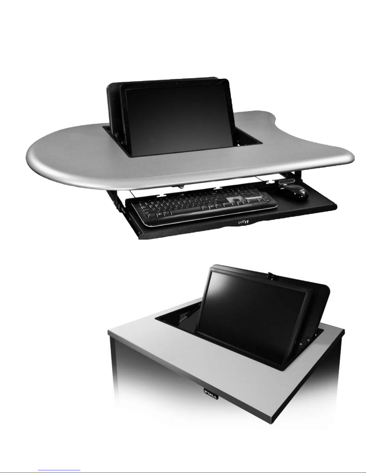
Models FIK-19 and FIK-23 include a keyboard
tray which assists in opening the flipIT® lid.
ATTENTION:
The weight of the monitor counterbalances the force of the
pneumatic cylinder (gas spring).
It is advised to install the gas spring just before installing
the monitor. If the gas spring is installed without a monitor,
take care to control the lid by hand. The lid will open too
fast if the monitor is not installed.
©2015 CBT Supply, Inc. dba SMARTdesks®. All rights reserved. SMARTdesks and flipIT® are registered trademarks of CBT Supply, Inc. REV 08252015
Models FIH-19 and FIH-23 have no keyboard
tray, but include a PULL handle for opening.
Page 2
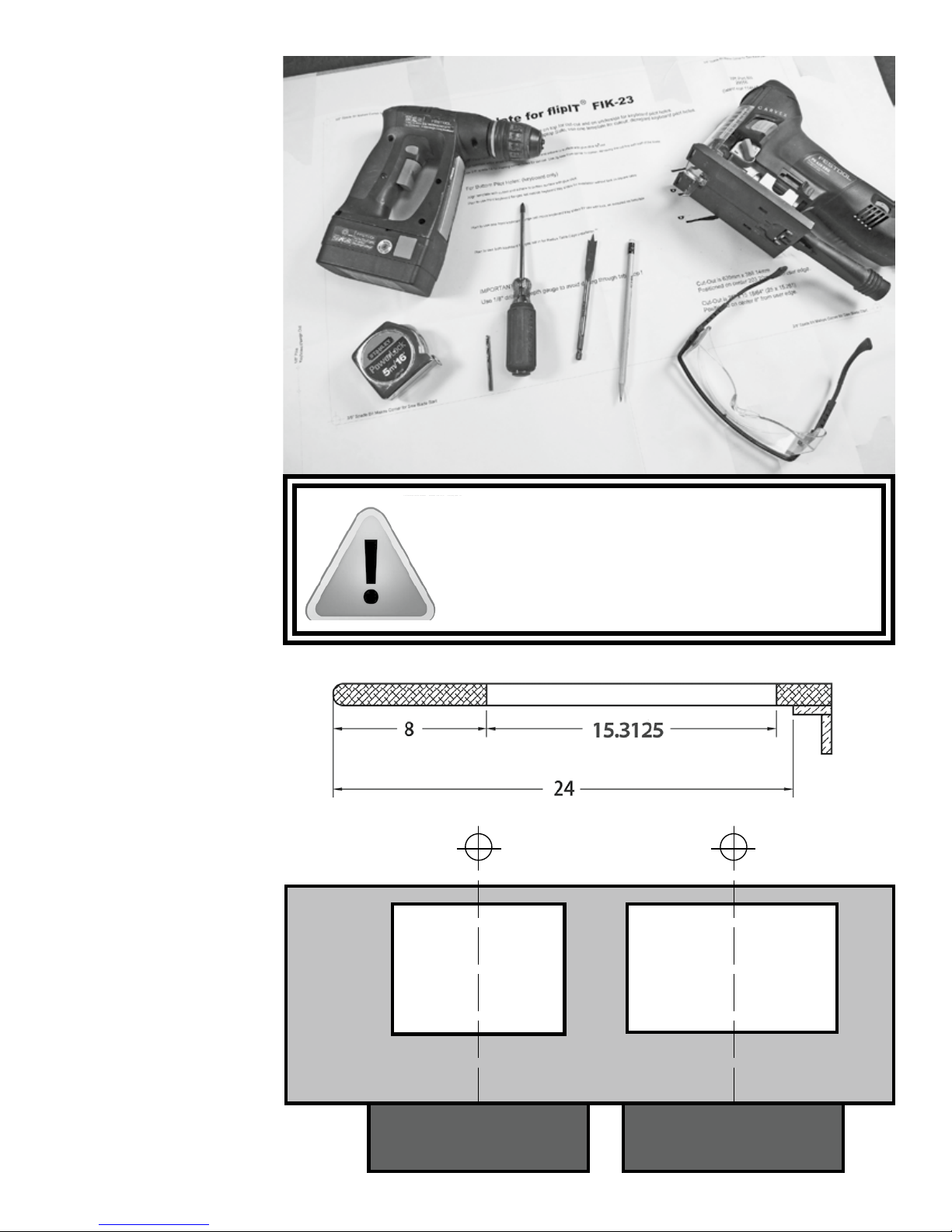
Tools needed for
full installation:
• power drill/screw gun
• tape measure
• commercial grade jig saw*
• Phillips #2 screwdriver bit
• 3/8” drill bit
• 1/8” drill bit
• pencil
• masking tape
• SAFETY GOGGLES
* STOP!
The installer must possess
the skill to cut within tolerance of the template layout
line if no factory-cutout is
made in the table top.
Do not attempt this
installation without this
level of craftsmanship skill.
Only skills of using a screw
driver and wrench are
required for installation into a
factory-made cutout.
Notes for easy
installation
Whenever possible, install the
flipIT before assembling the desk.
You will be installing from the top
and the underside: sawhorses
are recommended. If the desk is
assembled, see if the desktop can
be removed. Always protect the
surface of your desktop and work
safely with power tools.
• The template guides the
placement of the cutout 8”
from the user edge.
• If the front edge is contoured
concave or convex, experiment with a scrap piece to
allow placement of keyboard
tray or handle.
• When 2 or more ipITs are
installed side by side, keep a
30” interval between centers.
• Other factors may enter
in: the placement of legs,
brackets and CPU holders
may require greater distance
between centers.
26” table depth
overall
WARNING: PoWeR Tools ARe DANGeRous
Review the safety procedures supplied by your power tool
manufacturers for your safety’s sake. Always use safety glasses
and wear proper apparel that won’t get caught in moving parts.
CBT Supply, Inc. will not be held liable for misuse of tools and
disregard for power tool manufacturers’ safety precautions.
Position FIK workstations 30” between centers
2.875 depth on the approach side
FIK | FIH 19
20.62 x 15.312
8” table depth on the user side
for dual arm keyboard to retract
FIK | FIH 23
25 x 15.312
2 technical support 800-770-7042 www.smartdesks.com
Page 3
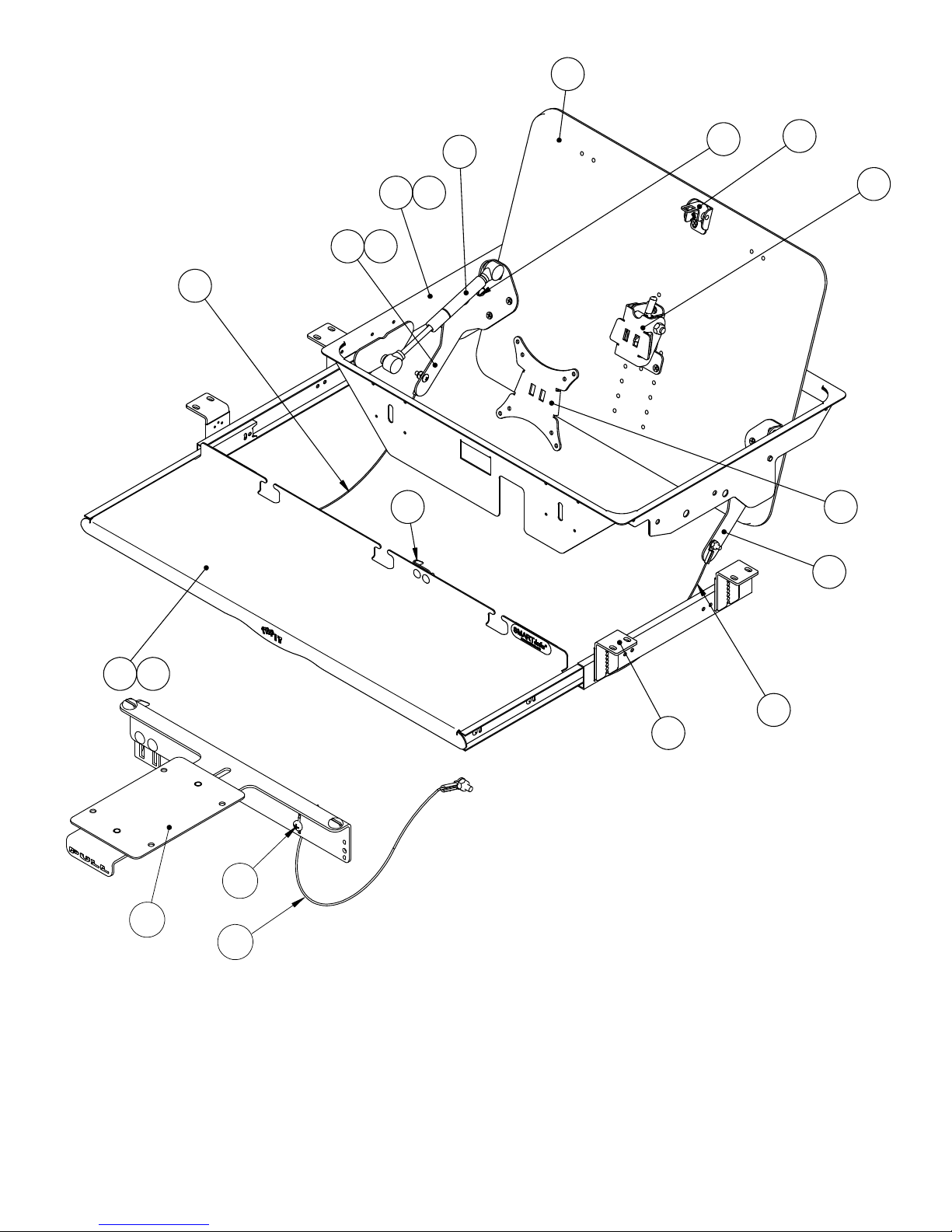
Parts and Hardware
1.2
FIK
1.3.3
1.3
1.6
1.5
1.11
1.3.1
2.8 3
1.9
1.8
1.4
2.1 2
5
4
FIH
1.4.3
Parts Identification
If there is an issue with function,
use this chart to identify the part
to our service team.
1.4.3
2.6
Item No. Qty. Part ID Description
1 1 31500 flipIT FIK|H-19 Desktop Assembly
1 1 31450 flipIT FIK|H-23 Desktop Assembly
1.1 1 31498 Grommet / Subassembly
1.2 1 31499 Top Lid
1.3 1 29784 LH Cable Arm Assembly
1.3.1 1 28473-LH LH Arm Catch Assembly
1.3.3 1 29763 Cable Assembly
1.4 1 29785 RH Cable / Arm Assembly
1.4.3 1 29763 Cable Assembly
1.5 2 27332 Bushing
1.6 1 27919 Gas Spring
1.8 1 28190 Flat Screen Tilt Assembly
1.9 1 31459 Pivot Keeper Assembly
2 1 31462 26”w Keyboard Tray Assembly
2.1 1 31455 26” Keyboard Tray Subassembly
2.6 4 29222 Slide Mounting Bracket
2.8 1 31456 Latch Hook
3 1 27888 VESA Mounting Bracket
4 1 31534 Latch / PULL Handle Assembly
5 1 TS295 #10-32 3/8 Trilobe
3
Page 4
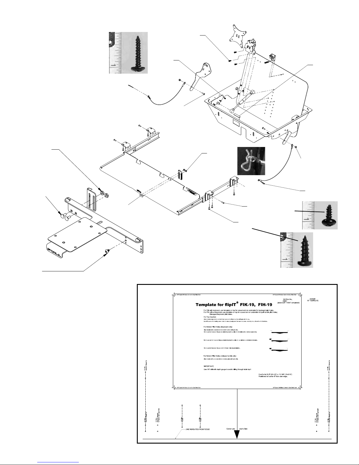
Parts
Identification
Hardware store specifications for
screws and nuts.
#10-24 NUT
(18399) (2)
EURO SCREW 16MM LONG
WOOD SCREW
(28163) (11)
#6 X 3/4 TRUSS HEAD (low profile)
WOOD SCREW
(TS313) (10)
#10-24 X 5/8 MACHINE SCREW
(MS330) (2)
#10-24 NUT
(18399) (2)
STOP PAD
(27910) (2)
#10-24 NYLON
INSERT LOCK NUT
(N130) (2)
#10-24 CARRIAGE BOLT
(MS278) (2)
#10-24 CARRIAGE BOLT
(MS278) (2)
#10-32 X 3/8 PH,PR,TRILOBE
(TS295) (1)
Paper template
Provided appropriate for your flipIT Kit:
Not used when installing into a factory
made, flipIT Ready product.
COTTER PIN
#8 X 3/8 ROUND HEAD
SELF TAPPING SCREW
(TS290) (4)
#10 X 5/8 ROUND HEAD
WOOD SCREW (21486) (8)
COTTER PIN
(21166) (2)
Cut-out placement is referenced from
the center line of the user space. Make
the cut-out top surface up. The spade
bit will make a clean hole from the top.
The same template is used on the
underside for making pilot holes for
keyboard tray or PULL handle, referencing the center line of the user side front
edge.
4 technical support 800-770-7042 www.smartdesks.com
Page 5
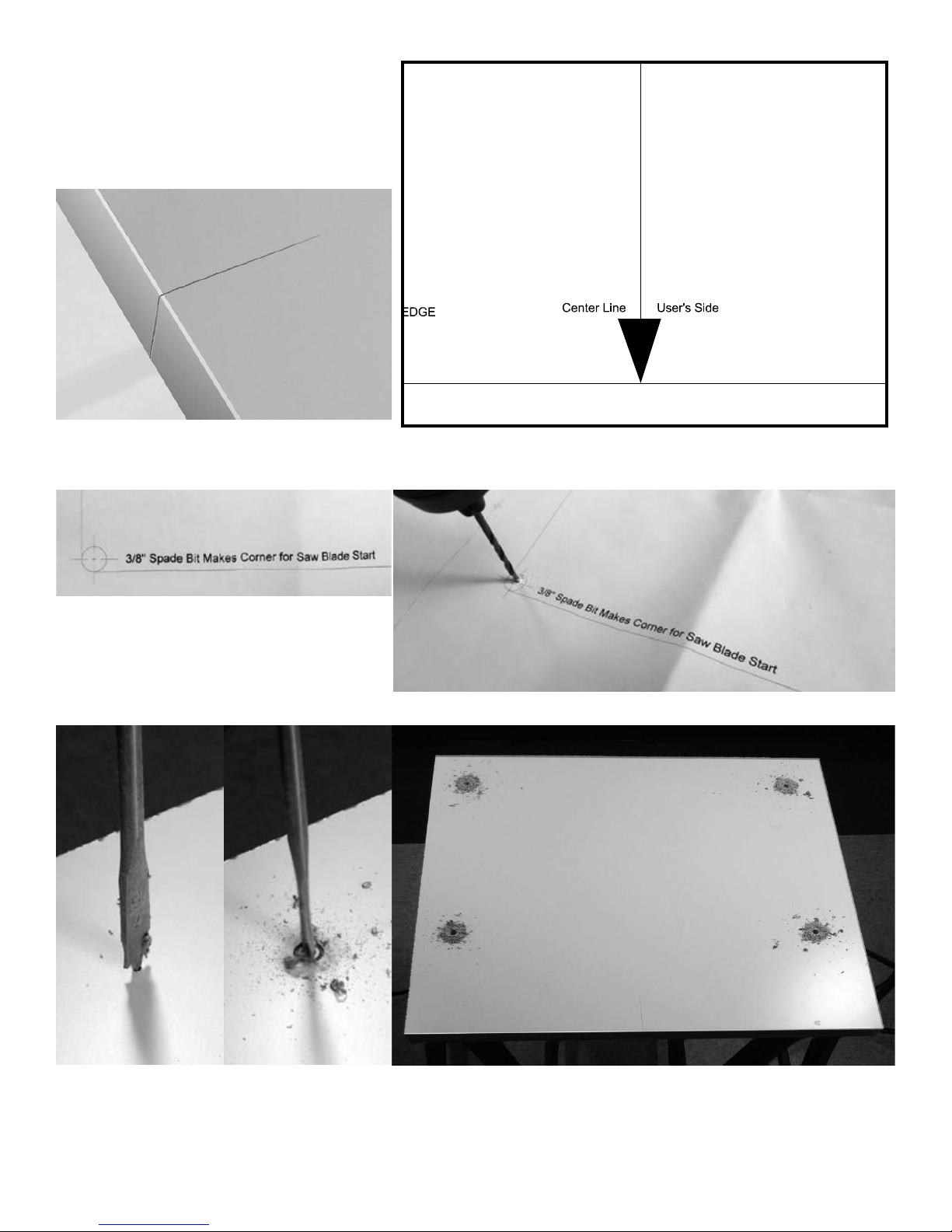
Make cutout using template
• Determine the center of the user space and
mark this center line in pencil.
• Fold template at user edge and align with
center line and front edge
• For accurate placement , use a 1/8” drill bit to
mark the drilling center for the 3/8” spade bit.
• After all 4 centers are marked,
carefully remove the template.
• Table top surface up: tape the template in position,
keeping the paper as flat as possible.
• Using your drill center pilots… …make 4 corner holes in your desktop using a 3/8” spade bit.
5
Page 6
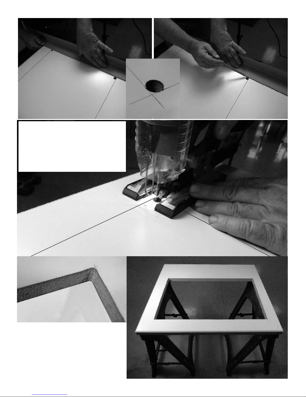
• Use a straight edge to scribe lines for mak-
ing the cut-out that are tangent to the 3/8”
holes
• Use a jig saw, starting the cut at the point
of tangency
• Remove the scribed line with the kerf of
the blade
• Your corners should look like the above
• Your perfectly cut table top should look like
the one on the right
• The flipIT collar has a trim flange that will
hide any slight imperfections in the cut line
and finish the installation
6 technical support 800-770-7042 www.smartdesks.com
Page 7
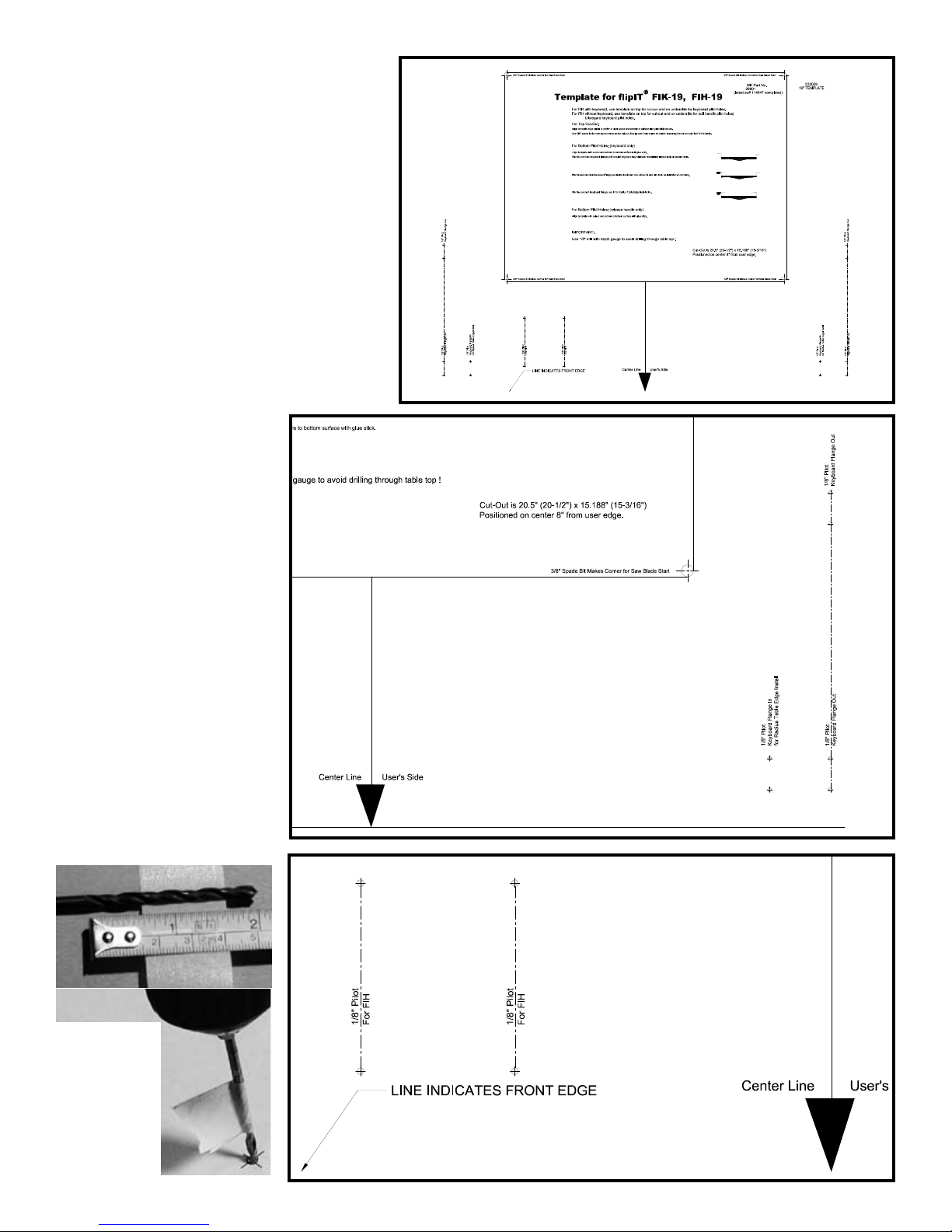
Make pilot holes for Keyboard
Tray (FIK) or Pull Handle (FIH)
• Turn the table top over to work on the
underside
• If you are installing the FIK-19 or FIK-23, use
the same template used for making the top
cut-out.
• Align the template to the Center Line of the
user side. You will also be able to reference
the actual cut-out to assure alignment.
• Use a 1/8” drill bit to
scribe the placement
of the pilot holes
• Note that the choice of
flange in or flange out is
possible to accommodate
the tight placement of other
fixtures or base
cabinet restrictions.
• If you need to change your
mind about which to use,
scribe all of the pilot holes.
• To finish the pilot holes,
remove the paper
template, use a depth gauge
on the drill bit, and make
3/8” deep holes.
• Takecaretonotdrillcompletelythroughyourtable
topandruinthesurface!
Make a
depth gauge
using tape
if you don’t
have a metal
one with a
set screw.
• The FIH section of the template is
used to mount the PULL Handle on
the user’s right, referenced from the
CenterLine and user edge.
• Scribe the position with the 1/8” drill
bit, remove the template and finish
the pilot holes with a depth gauge.
7
Page 8
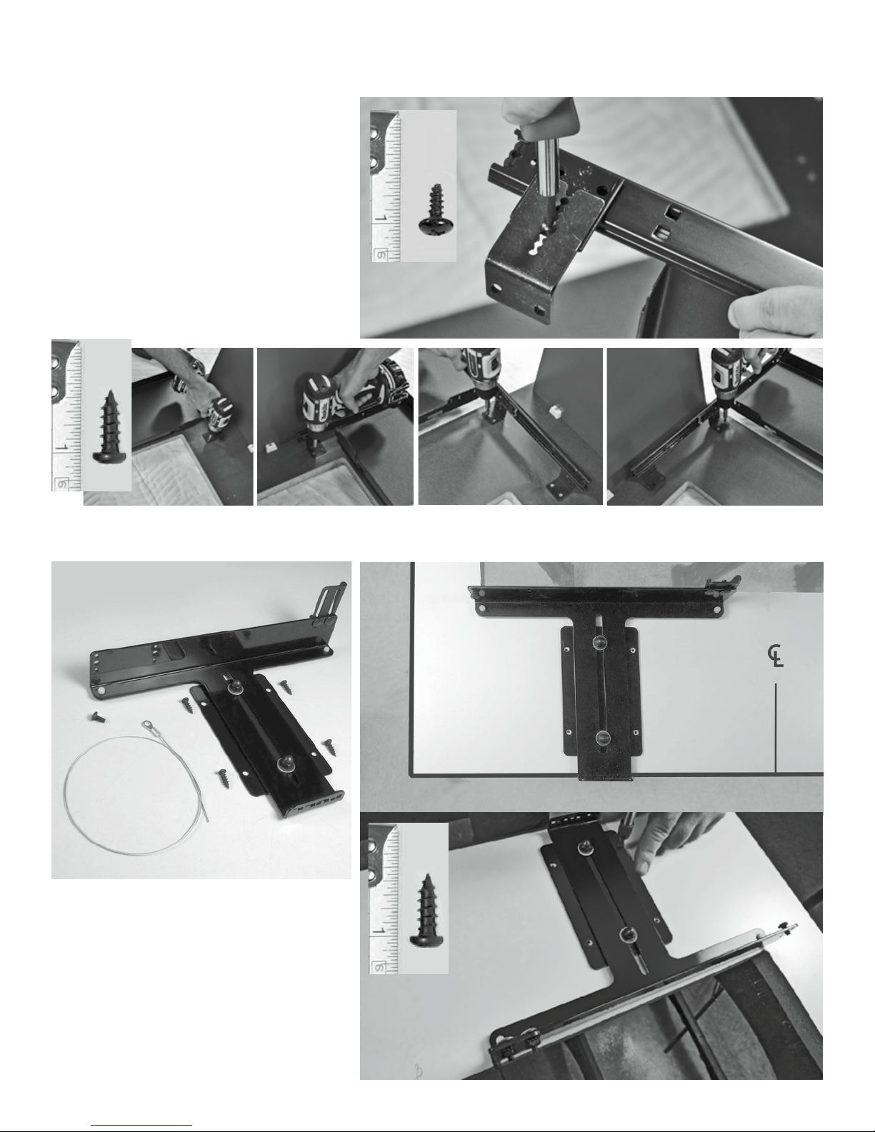
Installationintofactorymade,ipIT-Readytop
FIK-19 and FIK-23 Models
• Assess the installation advantages of mounting L bracket flanges in (toward the Center
Line) or flanges out (away from the Center
Line).
• Using the four self-tapping metal screws, select the 4th notch of the L bracket and install
the four L brackets.
• Place keyboard tray over the pilot holes and
install with screw gun and #2 Phillips blade:
eight #10, 5/8” round head wood screws.
FIH-19 and FIH-23 Models
• The PULL Handle assembly includes four
#10, 5/8” round head wood screws, a
cable with eyelet end and a self-tapping
metal screw— #10-32 x 3/8 PH, PR, Trilobe
(TS295)— used to connect the flipIT lid to
the assembly.
• Position the assembly over the pilot holes
and install it with the wood screws
8 technical support 800-770-7042 www.smartdesks.com
Page 9
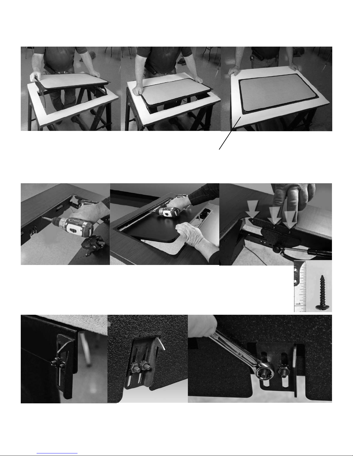
InstalltheipIT®intotheCut-Out(allmodels)
• Hold the flipIT lid assembly by the
trim collar
• Let the cable drop through the
cut-out and orient the assembly
diagonally to capture the cable arm
assemblies
Userside
• Install the collar using a screw gun with
#2 Phillips blade in eight places: 4 corners,
middle of front and back sides, and two above
the anchor plate and post for the gas spring
to give it extra reinforcement.
• Align the flipIT lid to the cut-out
• Note: the corners are fragile until
Approachside
installed
• Span your grasp to avoid
pinching your fingers and let the
assembly drop into place
FourCorners Twoabovegas
springanchorplate
• Use #6 x 3/4 Truss Head (low prole)
Wood Screws
• The lid latch hook registers to the
same position for both the FIK and
FIH flipIT models
• Top thicknesses vary, and the latch
hook must pass through the keeper,
which is mounted to the lid.
Use a 3/8” open end wrench to make
the adjustment for smooth opening
and closing. The gas spring must be
operational.
9
Page 10
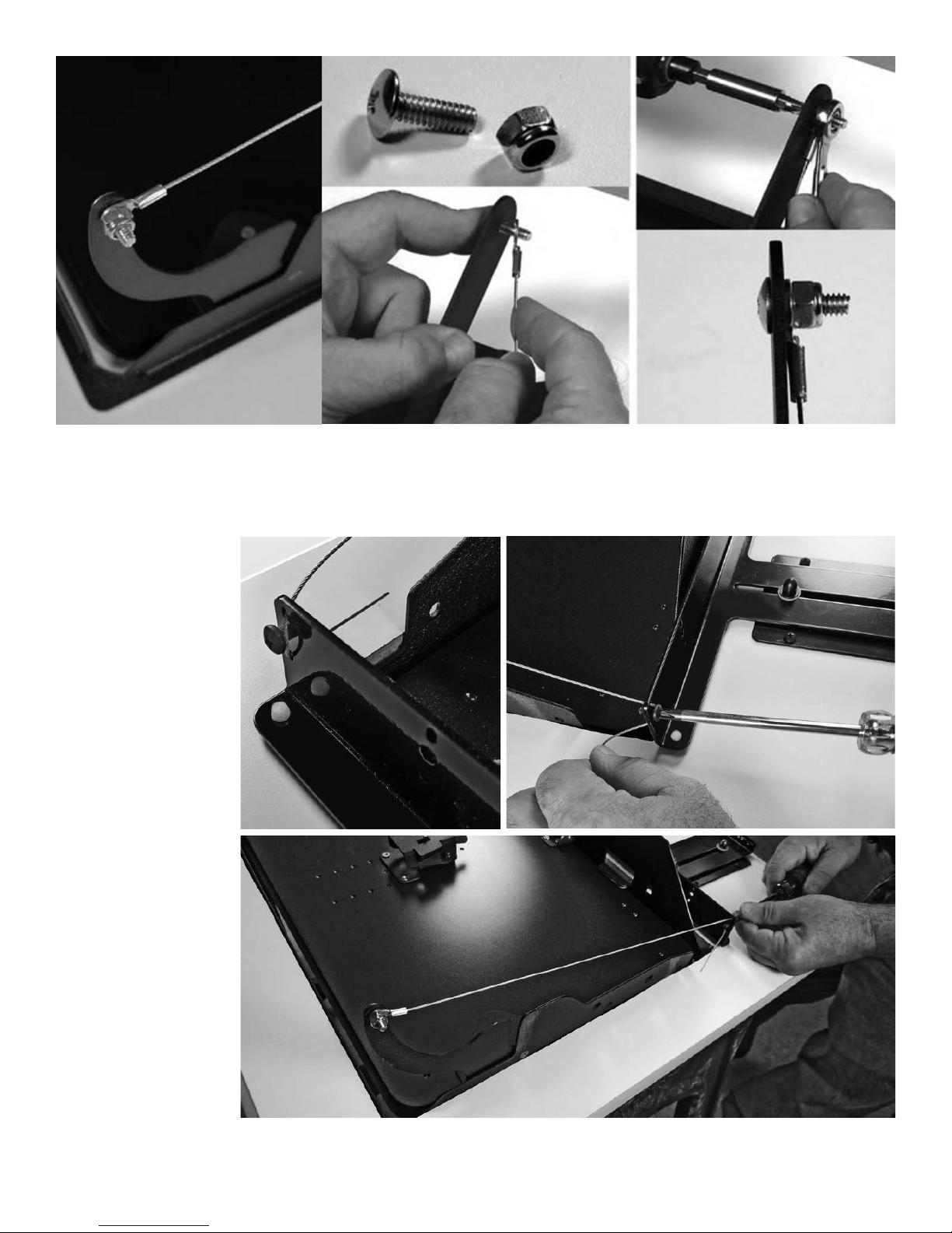
Cables should be attached loosely
The cable on the flipIT cable arm assembly ships attached, but
if it should need adjustment, do not overtighten the cable. It
needs to work freely. Adjust it with a 3/8” open end wrench
and #2 Phillips blade screwdriver.
FIHModels
Attaching
cable arm to
PULL handle
• Thread the cable to
the set of holes that
line up with the FIH19 or FIH-23 model.
• FIH-19 inside hole set
• FIH-23 outside hole
set
• Install the selftapping metal screw
into the middle hole
• Tension the cable so
it is a straight line, but
not as tight as a guitar
string. If the cable is
over-stretched the lid
will not close flush.
• Too much slack, and
the tipping point may
not be reached for
opening.
• Fully tighten the
screw to hold the
cable in place:
#2 Phillips blade.
10 technical support 800-770-7042 www.smartdesks.com
Outside Hole Set
for FIH-23
Inside Hole Set
for FIH-19
Page 11
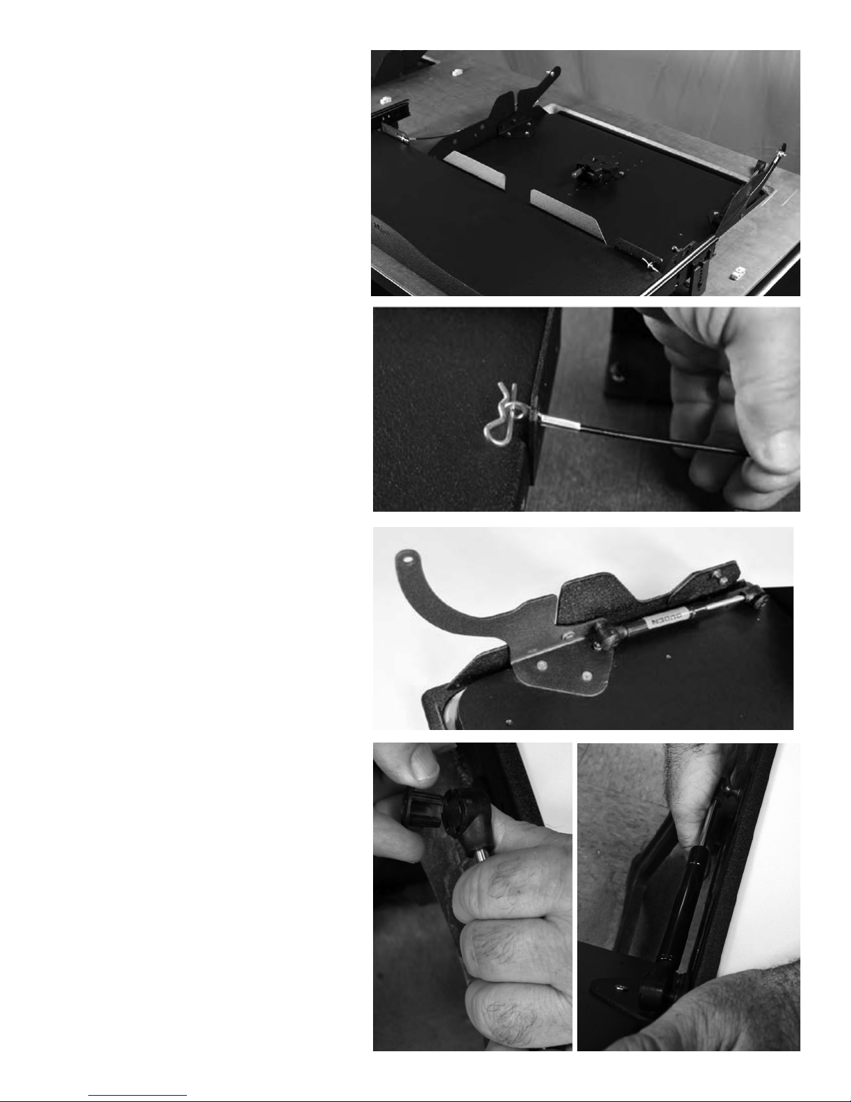
FIKModels
Attach cables with cotter pins
• The dual arm keyboard tray has slots that
align with the FIK-19 and FIK-23
• Choose the slot that gives the cable the most
freedom to move without being tangled.
• Slip the cotter pin through the eyelet in the
end of the cable to secure it.
• NOTE: If the cable tension is too tight, the lid
will not close. If this occurs, it is likely that the
keyboard tray is too far forward to the user
side. The easiest remedy is to use a small 3/8”
S hook you can purchase at a hardware store
to lengthen the cable. Cable ties will also
work.
Attach gas spring
• The gas spring ships attached to the flipIT lid
assembly
• Pry off the locking hub on the free end with a
flat blade screwdriver
• Press the gas spring to the post on the frame
• Replace the locking hub by pressing it in place
• NOTE:
The chrome shaft end of the gas spring
attaches to the frame to
prolong its service life.
11
Page 12
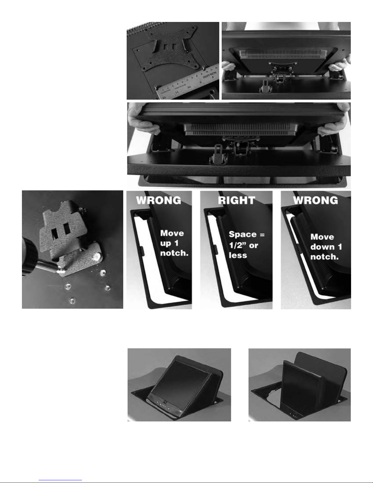
Install VESA mount
• Remove the stand from your
monitor and use the screws
provided with your display to
install the female part of the
mount.
• Bring the monitor to the male
half of the mounting system
and let the monitor snug into
place. Gravity does the work.
• A spring loaded keeper pin
with a red release knob will
engage.
• To remove the display, push
back the keeper and lift the
display up out of the couple.
The male half of the VESA mount is
attached to the flipIT lid with three
Euroscrews. Additional mounting
locations, at half-inch intervals, are
The VESA mount
provides screen
angle adjustment.
12 technical support 800-770-7042 www.smartdesks.com
provided to fine-tune the balance
of the opening performance. If the
monitor is mounted too high, it will
not pass through the cutout.
• Adjust the screen angle by grasping
the lid and display top and squeeze
the top to reduce the angle.
If it is mounted too low, the opening
might be too fast (like jumping off a
teeter totter).
• Increase the angle by holding the
lid with one hand and the top of the
display with the other, then bring the
display toward you.
 Loading...