

Flin Energy 3kVA-24V, 5kVA-48V User Manual

User Manual
FlinSlim Edge
Solar Hybrid Inverter
With Inbuilt Stabilizer
Version: 1.1

FlinSlim Edge Solar Hybrid Inverter with In-Built Stabilizer
Table Of Contents
ABOUT THIS MANUAL ..................................................................................................................... 1
Purpose ................................................................................................................................................ 1
Scope ................................................................................................................................................... 1
SAFETY INSTRUCTIONS .................................................................................................................. 1
INTRODUCTION .............................................................................................................................. 1
Features ............................................................................................................................................... 2
Basic System Architecture ...................................................................................................................... 2
Product Overview .................................................................................................................................. 3
INSTALLATION ............................................................................................................................... 3
Unpacking and Inspection ...................................................................................................................... 3
Installation ........................................................................................................................................... 4
Battery Connection ................................................................................................................................ 5
AC Input/Output Connection .................................................................................................................. 7
PV Connection....................................................................................................................................... 8
Communication Connection .................................................................................................................. 10
OPERATION .................................................................................................................................. 11
Power ON/OFF .................................................................................................................................... 11
Operation and Display Panel ................................................................................................................ 11
LCD Display Icons ............................................................................................................................... 12
LCD Setting ........................................................................................................................................ 13
Display Setting .................................................................................................................................... 19
Operating Mode Description ................................................................................................................. 21
Fault Reference Code .......................................................................................................................... 22
Warning Indicator ............................................................................................................................... 23
SPECIFICATIONS .......................................................................................................................... 23
TROUBLE SHOOTING .................................................................................................................... 27
Appendix I: Parallel function (Only for 5K model) ....................................................................... 28
Appendix II: Approximate Back-up Time Table ........................................................................... 41

FlinSlim Edge Solar Hybrid Inverter with In-Built Stabilizer
FLIN ENERGY
1
ABOUT THIS MANUAL
Purpose
This manual describes the assembly, installation, operation and troubleshooting of this unit. Please read
this manual carefully before installations and operations. Keep this manual for future reference.
Scope
This manual provides safety and installation guidelines as well as information on tools and wiring.
SAFETY INSTRUCTIONS
WARNING: This chapter contains important safety and operating instructions. Read
and keep this manual for future reference.
1. Before using the unit, read all instructions and cautionary markings on the unit, the batteries and all
appropriate sections of this manual.
2. CAUTION --To reduce risk of injury, charge only deep-cycle lead acid type rechargeable batteries.
Other types of batteries may burst, causing personal injury and damage.
3. Do not disassemble the unit. Take it to a qualified service center when service or repair is required.
Incorrect re-assembly may result in a risk of electric shock or fire.
4. To reduce risk of electric shock, disconnect all wirings before attempting any maintenance or cleaning.
Turning off the unit will not reduce this risk.
5. CAUTION – Only qualified personnel can install this device with battery.
6. NEVER charge a frozen battery.
7. For optimum operation of this inverter/charger, please follow required spec to select appropriate cable
size. It’s very important to correctly operate this inverter/charger.
8. Be very cautious when working with metal tools on or around batteries. A potential risk exists to drop
a tool to spark or short circuit batteries or other electrical parts and could cause an explosion.
9. Please strictly follow installation procedure when you want to disconnect AC or DC terminals. Please
refer to INSTALLATION section of this manual for the details.
10. Fuses (6 pieces of 40A, 32VDC for 3KVA and 1 piece of 200A, 58VDC for 5KVA) are provided as over-
current protection for the battery supply.
11. GROUNDING INSTRUCTIONS -This inverter/charger should be connected to a permanent grounded
wiring system. Be sure to comply with local requirements and regulation to install this inverter.
12. NEVER cause AC output and DC input short circuited. Do NOT connect to the mains when DC input
short circuits.
13. Warning!! Only qualified service persons are able to service this device. If errors still persist after
following troubleshooting table, please send this inverter/charger back to local dealer or service center
for maintenance.
INTRODUCTION
This is a multi-function inverter/charger, combining functions of inverter, AVR, solar charger and battery
charger to offer uninterruptible power for office and home appliances. Its comprehensive LCD display offers
FlinSlim Edge Solar Hybrid Inverter with In-Built Stabilizer
FLIN ENERGY
2
user-configurable and easy-accessible button operation such as battery charging current, AC/solar charger
priority, and acceptable input voltage based on different applications.
Features
Pure sine wave inverter
Built-in solar charge controller
Built in boost and buck AVR for voltage regulation
Configurable home appliances and personal computers via LCD setting
Configurable battery charging current based on applications via LCD setting
Configurable AC/Solar Charger priority via LCD setting
Compatible to mains voltage or generator power
Auto restart while AC is recovering
Overload/ Over temperature/ short circuit protection
Smart battery charger design for optimized battery performance Cold start function
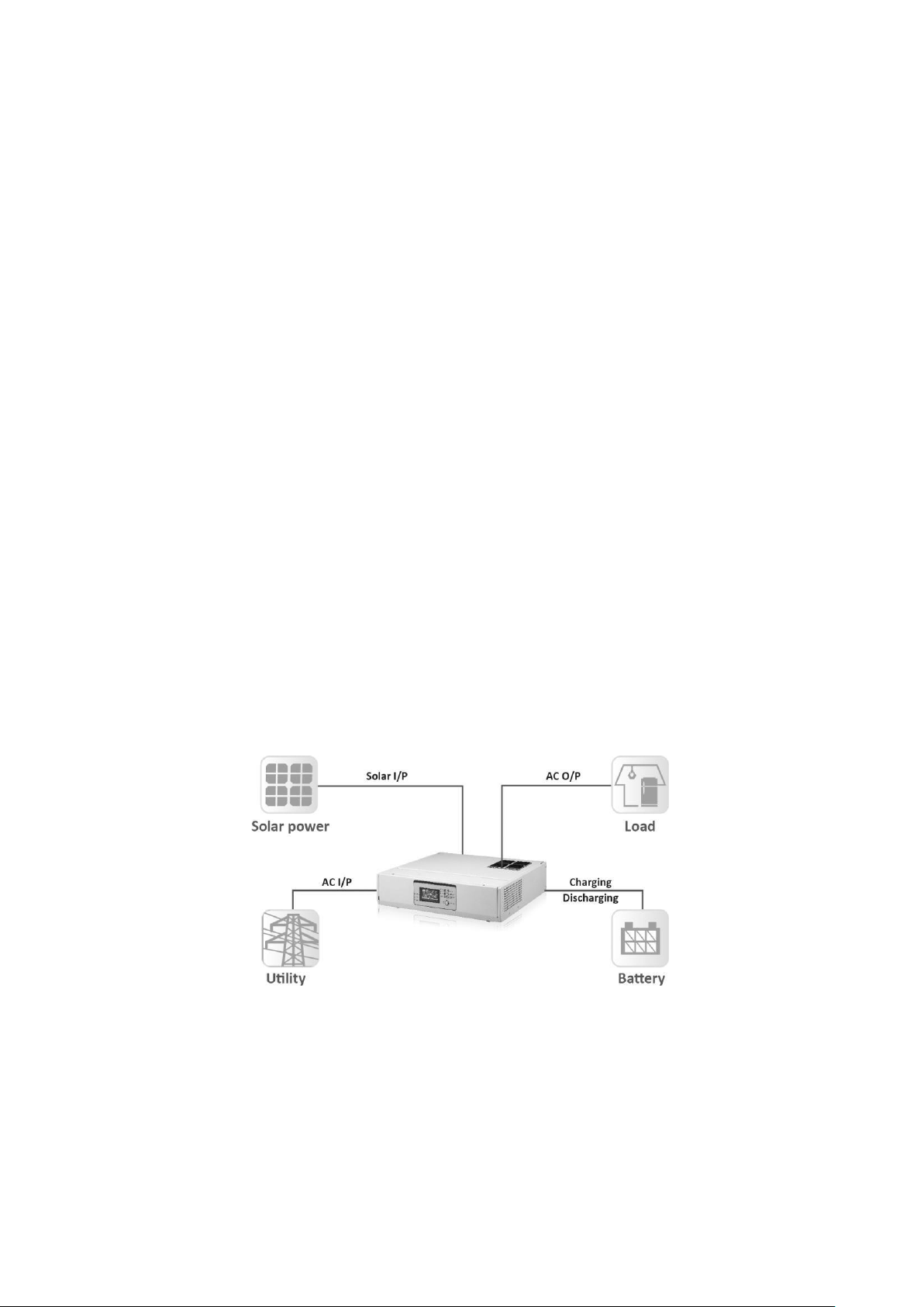
Basic System Architecture
The following illustration shows basic application for this inverter/charger. It also includes following devices to
have a complete running system:
Generator or Utility.
PV modules (option)
Consult with your system integrator for other possible system architectures depending on your requirements.
This inverter can power all kinds of appliances in home or office environment, including motor-type appliances
such as tube light, fan, refrigerator and air conditioner.
Figure 1 Hybrid Power System
FlinSlim Edge Solar Hybrid Inverter with In-Built Stabilizer
FLIN ENERGY
3
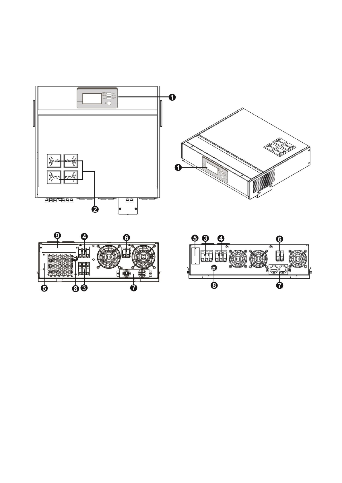
Product Overview
Wall-mounted Desktop
5K 3K
1. Operation panel
2. Output sockets
3. AC output terminal
4. AC input
5. Communication port
6. PV input
7. Battery input
8. Circuit breaker
9. Parallel connectors
(only available for parallel models)
INSTALLATION
Unpacking and Inspection
Before installation, please inspect the unit. Be sure that nothing inside the package is damaged. You should
have received the following items inside of package:
FlinSlim Edge Solar Hybrid Inverter with In-Built Stabilizer
FLIN ENERGY
4
The unit x 1
User manual x 1
Communication cable x 2
Software CD x 1
Mounting plate x 1
Screws x 4
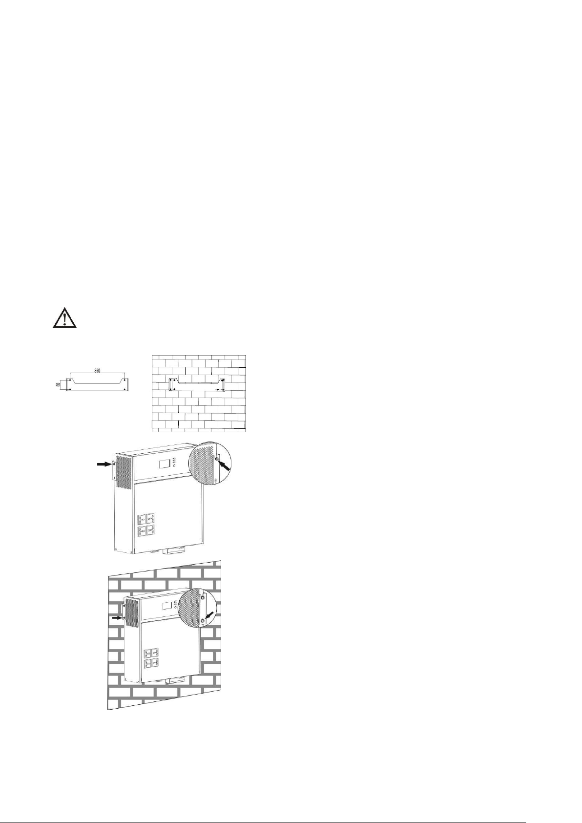
Installation
Wall mounted
Consider the following points before selecting where to install:
Do not mount the inverter on flammable construction materials.
Mount on a solid surface
Install this inverter at eye level in order to allow the LCD display to be read at all times.
The ambient temperature should be between 0°C and 55°C to ensure optimal operation. The
recommended installation position is to be adhered to the wall vertically.
For proper air circulation to dissipate heat, allow a clearance of approx. 20 cm to the side and approx. 50
cm above and below the unit.
SUITABLE FOR MOUNTING ON CONCRETE OR OTHER NON-COMBUSTIBLE SURFACE ONLY.
Please follow the steps as below to finish the installation.
Employ the mounting plate as a template for marking the
positions of the boreholes. Mount the mounting plate with
supplied screws to fix the plate in place.
Insert two screws to the two sides of inverter as showed in the
figure. Please don’t screw them tightly at this time. Then, place
the inverter onto the mounting plate and fix two screws tightly.
Then, insert the other two screws on the two sides of inverter
as showed in the figure and fix them tightly.
For proper air circulation to dissipate heat, please keep the
space around the inverter more than 20 cm.
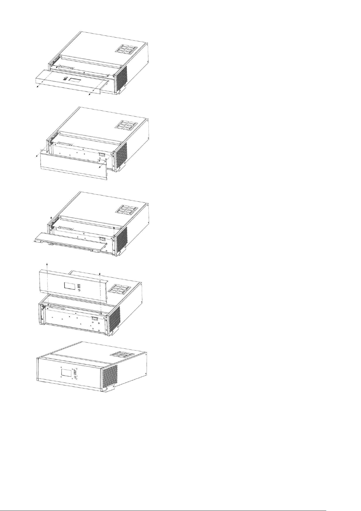
Desktop
The inverter can be switched to desktop form factor by
following the below steps:
FlinSlim Edge Solar Hybrid Inverter with In-Built Stabilizer
FLIN ENERGY
5
Take off the LCD panel by removing screws.
Remove the metal case showed in the figure.
Place the metal case to the position where the LCD panel was
previously removed and fix it with screws.
Place the LCD panel to the position where the metal case was
previously removed and fix it with two screws.
Place the inverter in a protected area that is free of excessive
dust and has adequate air flow. Please place the inverter away
from other units at least 20 cm to avoid interference.
Battery Connection
CAUTION: For safety operation and regulation compliance, it’s requested to install a separate DC over-current
protector or disconnect device between battery and inverter. It may not be requested to have a disconnect
device in some applications, however, it’s still requested to have over-current protection installed. Please refer
to typical amperage in below table as required fuse or breaker size.
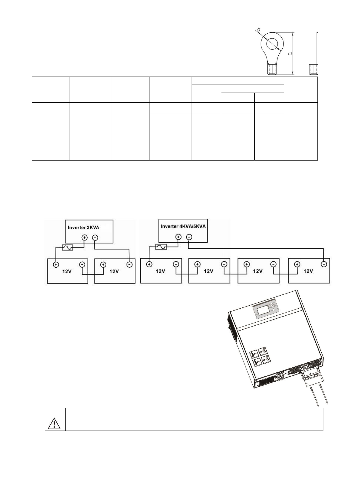
Ring terminal:
FlinSlim Edge Solar Hybrid Inverter with In-Built Stabilizer
FLIN ENERGY
6
WARNING! All wiring must be performed by a qualified personnel.
WARNING! It's very important for system safety and efficient operation to use
appropriate cable for battery connection. To reduce risk of injury, please use the
proper recommended cable and terminal size as below.
Recommended battery cable and terminal size:
Model
Typical
Amperage
Battery
capacity
Wire Size
Ring Terminal
Torque
value
Cable
mm2
Dimensions
D (mm)
L (mm)
3KVA
100A
100AH
200AH
1*4AWG
22
6.4
33.2
2~ 3 Nm
2*8AWG
14
6.4
29.2
5KVA
84A
200AH
1*4AWG
22
6.4
33.2
2~ 3 Nm
2*8AWG
14
6.4
29.2
Please follow below steps to implement battery connection:
1. Assemble battery ring terminal based on recommended battery cable and terminal size.
2. 3KVA model supports 24VDC system and 5KVA model supports 48VDC system. Connect all battery packs
as below chart. It’s suggested to connect at least 100Ah capacity battery for 3KVA model and at least
200Ah capacity battery for 5KVA model.
WARNING: Shock Hazard
Installation must be performed with care due to high battery voltage in series.
3. Insert
the ring terminal
of
battery
cable
flatly into battery connector
of inverter and make sure the bolts are tigh
tened
with
torque of
2 - 3 Nm . M ake sure polarity at both the batter
y and the inverter/charge
is correctly connected and
ring terminals are tightly screwed to the
battery terminals.

FlinSlim Edge Solar Hybrid Inverter with In-Built Stabilizer
FLIN ENERGY
7
CAUTION!! Do not place anything between the flat part of the inverter terminal and the ring
terminal. Otherwise, overheating may occur.
CAUTION!! Do not apply anti-oxidant substance on the terminals before terminals are connected
tightly.
CAUTION!! Before making the final DC connection or closing DC breaker/disconnector, be sure
positive (+) must be connected to positive (+) and negative (-) must be connected to negative
(-).
AC Input/Output Connection
CAUTION!! Before connecting to AC input power source, please install a separate AC breaker between
inverter and AC input power source. This will ensure the inverter can be securely disconnected during
maintenance and fully protected from over current of AC input. The recommended spec of AC breaker is 30A
for 3KVA and 50A for 5KVA.
CAUTION!! There are two terminal blocks with “IN” and “OUT” markings. Please do NOT mis-connect input
and output connectors.
WARNING!! When using sockets as the output, please make sure that the current of each socket is less than
10A, in case of electric hazard.
WARNING! All wiring must be performed by qualified person.
WARNING! It's very important for system safety and efficient operation to use appropriate cable for AC input
connection. To reduce risk of injury, please use the proper recommended cable size as below.
Suggested cable requirement for AC wires
Model
Gauge
Torque Value
3KVA
12 AWG
1.2~ 1.6 Nm
5KVA
8 AWG
1.4~ 1.6Nm
Please follow below steps to implement AC input/output connection:
1. Before making AC input/output connection, be sure to open DC protector or disconnect first.
2. Remove insulation sleeve 10mm for six conductors.
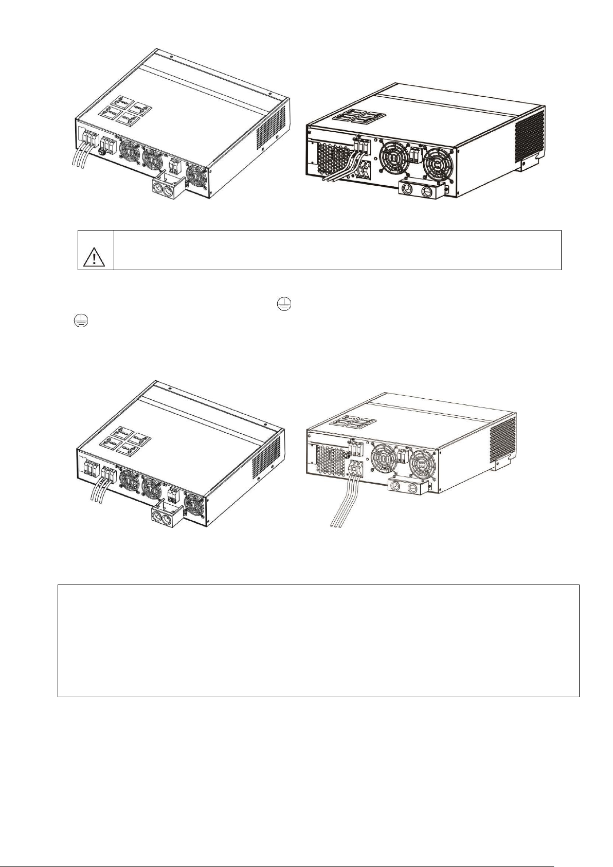
3. Insert AC input wires according to polarities indicated on terminal block and tighten the terminal screws.
Be sure to connect PE protective conductor ( ) first.
→Ground (yellow-green)
L→LINE (brown or black)
N→Neutral (blue)
FlinSlim Edge Solar Hybrid Inverter with In-Built Stabilizer
FLIN ENERGY
8
3K 5K
WARNING:
Be sure that AC power source is disconnected before attempting to fix the wire to the unit.
4. Then, insert AC output wires according to polarities indicated on terminal block and tighten terminal screws.
Be sure to connect PE protective conductor ( ) first.
→Ground (yellow-green) L→LINE
(brown or black)
N→Neutral (blue)
3K 5K
5. Make sure the wires are securely connected.
CAUTION: Appliances such as air conditioner are required at least 2~3 minutes to restart because it’s required to
have enough time to balance refrigerant gas inside of circuits. If a power shortage occurs and recovers in a short
time, it will cause damage to your connected appliances. To prevent this kind of damage, please check manufacturer
of air conditioner if it’s equipped with time-delay function before installation. Otherwise, this inverter/charger will
trig overload fault and cut off output to protect your appliance but sometimes it still causes internal damage to the
air conditioner.
PV Connection
CAUTION: Before connecting to PV modules, please install separately a DC circuit breaker between inverter
and PV modules.
WARNING! All wiring must be performed by a qualified personnel.
WARNING! It's very important for system safety and efficient operation to use appropriate cable for PV module
connection. To reduce risk of injury, please use the proper recommended cable size as below.
FlinSlim Edge Solar Hybrid Inverter with In-Built Stabilizer
FLIN ENERGY
9
Model
Typical Amperage
Cable Size
Torque
3KVA W/O MPPT
50A
8 AWG
1.4~1.6 Nm
3KVA With MPPT
40A
8 AWG
1.4~1.6 Nm
5KVA W/O MPPT
50A
8 AWG
1.4~1.6 Nm
5KVA With MPPT
60A
8 AWG
1.4~1.6 Nm
PV Module Selection:
When selecting proper PV modules, please be sure to consider below parameters:
1. Open circuit Voltage (Voc) of PV modules not exceeds max. PV array open circuit voltage of inverter.
2. Open circuit Voltage (Voc) of PV modules should be higher than min. battery voltage.
C
Note: * Vmp: panel max power point voltage.
The PV charging efficiency is maximized while PV system voltage is close to Best Vmp.
Maximum PV module numbers in Series: Vmpp of PV module * X pcs ≒ Best Vmp of Inverter or Vmp
range
PV module numbers in Parallel: Max. charging current of inverter / Impp
Total PV module numbers = maximum PV module numbers in series * PV module numbers in parallel
Take 5K W/O MPPT model inverter as an example to select proper PV module. After considering Voc of PV
module not exceed 105Vdc and max. Vmpp of PV module close to 60Vdc or within 56Vdc ~ 72Vdc, we can
choose PV module with below specification.
Maximum Power (Pmax)
260W
Max. PV module numbers in series
2 30.9 x 2 ≒ 56 ~ 72
Max. Power Voltage Vmpp(V)
30.9V
Max. Power Current Impp(A)
8.42A
PV module numbers in parallel
6 50 A / 8.42
Total PV module numbers
2 x 6 = 12
Open Circuit Voltage Voc(V)
37.7V
Short Circuit Current Isc(A)
8.89A
Maximum PV module numbers in Series: 2
PV module numbers in Parallel: 6
Total PV module numbers: 2 x 6 = 12
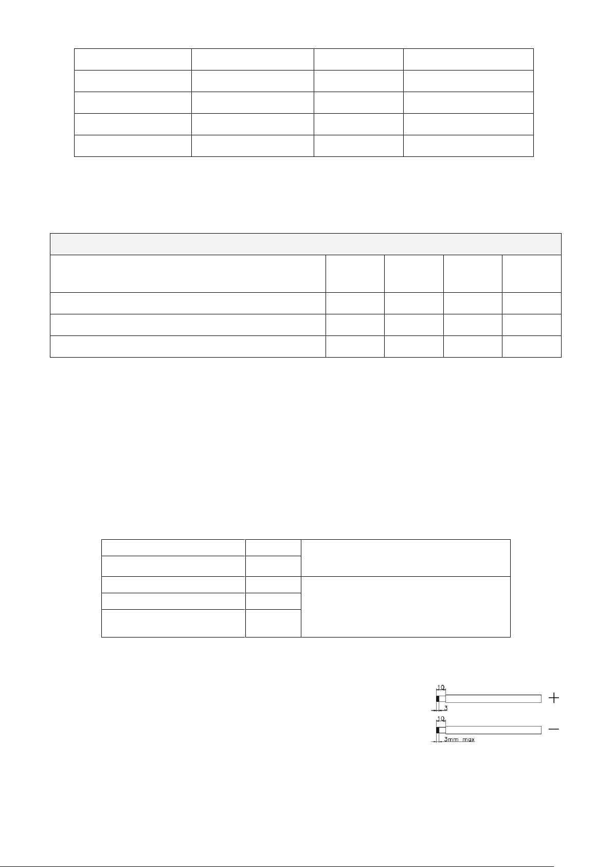
Please follow below steps to implement PV module connection:
1. Remove insulation sleeve 10 mm for positive and negative conductors.
2. Check correct polarity of connection cable from PV modules and PV input
connectors. Then, connect positive pole (+) of connection cable to positive
pole (+) of PV input connector. Connect negative pole (-) of connection cable to negative pole (-
) of PV input connector.
Solar Charger
INVERTER MODEL
3KVA
W/O MPPT
3KVA
With MPPT
5KVA
W/O MPPT
5KVA
With MPPT
Max. PV Array Open Circuit Voltage
75VDC
100VDC
105VDC
145VDC
Recommended PV Array MPPT Voltage Range: Vmp*
30~32VDC
30~80VDC
60~72VDC
60~115VD
Max. charging current
50A
40A
50A
60A

FlinSlim Edge Solar Hybrid Inverter with In-Built Stabilizer
FLIN ENERGY
10
3K 5K
3. Make sure the wires are securely connected.
Communication Connection
The inverter is equipped with communication port either RS-232 or USB. Please use supplied communication
cable to connect to inverter and PC. This communication port is also can be replaced with SNMP card. When
installing with SNMP card in the inverter, it will provide advanced communication and monitoring options.
After communication cable is connected well, insert bundled CD into a computer and follow on-screen
instruction to install the monitoring software. For the detailed software operation, please check user manual
of software inside of CD.
FlinSlim Edge Solar Hybrid Inverter with In-Built Stabilizer
FLIN ENERGY
11
OPERATION
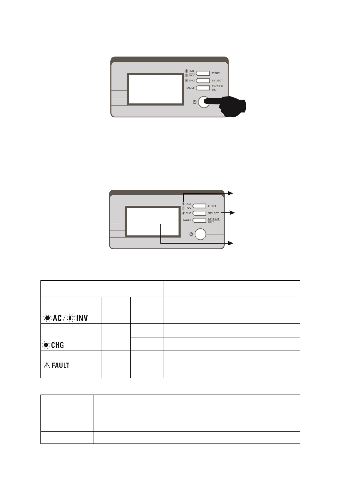
Power ON/OFF
Once the unit has been properly installed and the batteries are connected well, simply press On/Off switch
to turn on the unit.
Operation and Display Panel
The operation and display panel, shown in below chart, is on the front panel of the inverter. It includes
three indicators, four function keys and a LCD display, indicating the operating status and input/output
power information.
LED
indicators
Function
keys
LCD display
LED Indicators
LED Indicator
Messages
Green
Solid On
Output is powered by utility in Line mode.
Flashing
Output is powered by battery or PV in battery mode.
Green
Solid On
Battery is fully charged.
Flashing
Battery is charging.
Red
Solid On
Fault occurs in the inverter.
Flashing
Warning condition occurs in the inverter.
Function Keys
Function Key
Description
ESC
To exit setting mode
SELECT
To go to next page or next selection
ENTER
To confirm the selection in setting mode or enter setting mode
FlinSlim Edge Solar Hybrid Inverter with In-Built Stabilizer
FLIN ENERGY
12
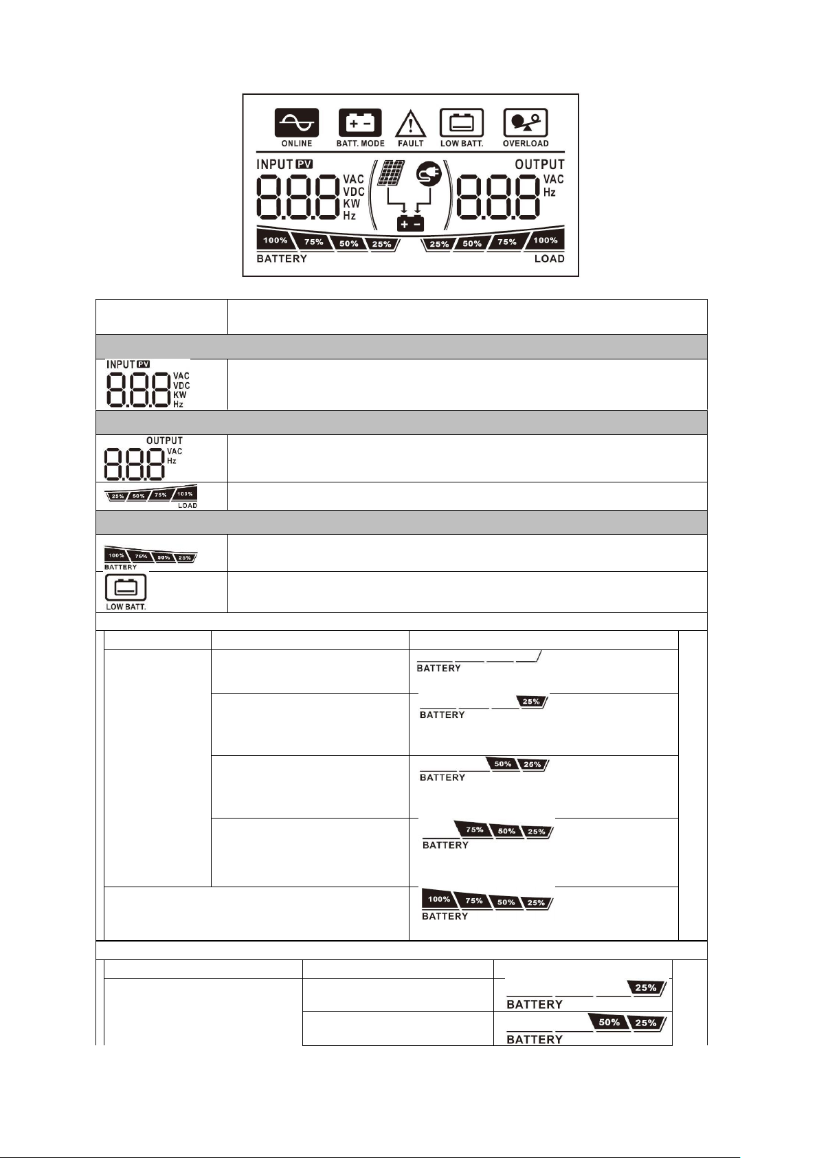
LCD Display Icons
Icon
Function description
Input Source Information
Indicate input voltage, input frequency, PV voltage, battery voltage and PV
input power, charging power or setting value.
Output Information
Indicate output voltage, output frequency, setting program NO or fault code.
Indicate load percentage
Battery Information
Indicates battery level by 0-24%, 25-49%, 50-74% and 75-100% in battery
mode and charging status.
Indicates battery voltage is low.
In line mode, it will present battery capacity as below table when unit is charging.
Status
Battery voltage
LCD Display
Constant
Current mode /
Constant
Voltage mode
<2V/cell
4
bars will flash in turns.
2 ~ 2.083V/cell
25% bar will be on and the other three bars
will flash in turns.
2.083 ~ 2.167V/cell
Two bars will be on and the other two bars
will flash in turns.
> 2.167 V/cell
Three bars will be on and the leftmost bar
will flash.
Floating mode. Batteries are fully charged.
4 bars will be on.
In battery mode, it will present battery capacity.
Load Percentage
Battery Voltage
LCD Display
Load >50%
< 1.717V/cell
1.717V/cell ~ 1.8V/cell
 Loading...