


Rhein Tech Laboratories, Inc. Client: FlightScope (Pty) Ltd
360 Herndon Parkway Model: Strike
Suite 1400 Standard: FCC 15.245
Herndon, VA 20170 FCC ID: QXP-32482
http://www.rheintech.com Report #: 2015225
Appendix H: User Manual
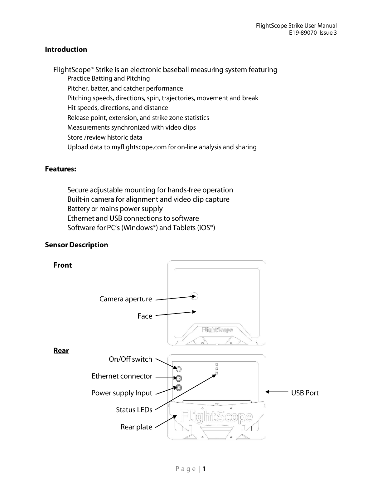
Please refer to the following pages.
Page 21 of 27


CAUTION
Take precautions to prevent the
sensor from being struck by a
ball. For example, place the
sensor behind a screen or erect
a non-metallic deflector in front
of the sensor for protection.
Choose a position for the
sensor. It must be set back
between 20 and 60 ft. behind
the home plate, and laterally
offset within the corresponding
minimum and maximum bounds
illustrated in the adjacent
figure. The lateral offset is
needed to avoid players
blocking the sensor’s view of
the ball.
The sensor can be mounted on
a vertical or horizontal pole
structure using the pole mount
bracket or on a heavy duty
tripod (not supplied).
The sensor must aim at the top
of the pitcher’s mound.
The height of the sensor must
be between 6 and 16 feet
depending on its distance
behind the home plate, as
shown in the diagram.
NOTE
Take care that the sensor does
not block spectators’ view, if
applicable.

The pole mount bracket can be strapped to a pole of at least 1½ inch diameter. The bracket is
factory configured for mounting against a vertical pole. The mounting can be changed for a horizontal
pole – see below.
Screw the clamping screws (1) and (2) partly out
(turning anticlockwise).
Place the mount (3) against the chosen pole (6) at a
suitable height from where the sensor will have a
clear view of the pitcher and batter.
Use the cambuckle straps (4) and (5) to tie the
mount to the pole. Orientate the bracket so that it is
approximately in the direction of the Pitcher’s Mound
against the pole.
Pull the straps tight enough around the pole to hold
the bracket in position against the pole.
Tighten the clamping screws (1) and (2) lightly by
turning them clockwise using the Allen key
(included).
Raise the Strike Sensor (7) and hook the slots (11)
in the Mounting Plate over the Strike Plate hooks
(12).
If needed, apply down pressure to push the sensor
unit completely down to engage slots securely on
the hooks.
Without disturbing the sensor direction, fasten the
clamping screws (1) and (2) firmly to lock the mount
securely to the pole.
Now pivot the Sensor Unit on the pole mount to
point the sensor face towards the pitcher’s mound,
using your best estimate of direction. It may be
necessary to loosen the pivot screw (8) slightly to
allow movement. When the pointing direction is
good, firmly tighten the pivot screw (8).
The mounting is now complete and the Unit can be
connected for use.

Remove the pivot screw (8) and washer to free the
Strike Plate (9) from the rear mount (3).
Rotate the rear mount (3) by 90 degrees, and attach
the Strike Plate (9) again using the removed pivot
screw (8) and washer in the rotated position.
The mount can now be attached to a horizontal
structure.
90

FlightScope Strike can be powered from a rechargeable external 12 V DC battery, or from a mainspowered AC adapter (both included).
Connect the supplied AC adapter (21) to
the Strike unit (20).
Connect the AC adapter to a wall socket
using the supplied mains power cord (22).
Switch the Strike unit on with the Power
switch (23).
NOTE: Make sure the battery has
sufficient charge before using, so that
operation can be uninterrupted.
Connect the battery (24) to the Strike unit
(20) using the supplied battery cable
(25).
Place the battery in the compartment (26)
behind the Strike unit.
Switch the Strike unit on with the Power
switch (23).
The supplied battery is a 20,000 mAH capacity rechargeable Li-Ion technology battery pack. The
original manufacturer’s specifications and instructions apply. The original battery charger/adapter is
included.

http://downloads.flightscope.com/download.php?file=/Software/FlightScopeBaseball/BaseballHost_Setup
_v4.13.28.exe
itunes.apple.com


None
Off
Blue blinking
Communications idle, not connected to a
PC/device
Blue solid
Communications active, connected to a
PC/device
None
Off
Amber solid
Transmitter on
None
Off
Blue blink fast
Starting
Blue blink slow
Sleeping
Blue solid
Error
Green blink fast
Processor starting
Green blink slow
Processor on/Idle
Green/Red alt
Ready to measure
Power supply: 12V dc @ 1A (12W)
FCC Class 18
Dimensions – sensor unit: 13½ x 11½ x 5½ Inches (wide x high x deep)
Dimensions – pole mount: 11 x 7½ x 5¼ Inches (wide x high x deep)
Mass – sensor unit: 10 lbs
Mass – pole mount: 2.5 lbs
Ingress protection: NEMA 3S / IP54


 Loading...