

Page 1
1
USER MANUAL
USER MANUAL
V.1
© 2023 Flightory by Szymon Wójcik All rights reserved.
Page 2
Socials
USER MANUAL
2
Join Flightory Tech group on Facebook and create community with us.
Share progress of your builds. Any suggestions or questions welcome.
www.facebook.com/groups/flightory
Join our Discord server as well, where the discussions are organized
by topics, and the interaction between users is lively.
https://discord.gg/GPMgDZ3Cxv
Follow us on Instagram for regular updates and fresh content
www.instagram.com/flightory_
Page 3
General Aircraft Data
USER MANUAL
3
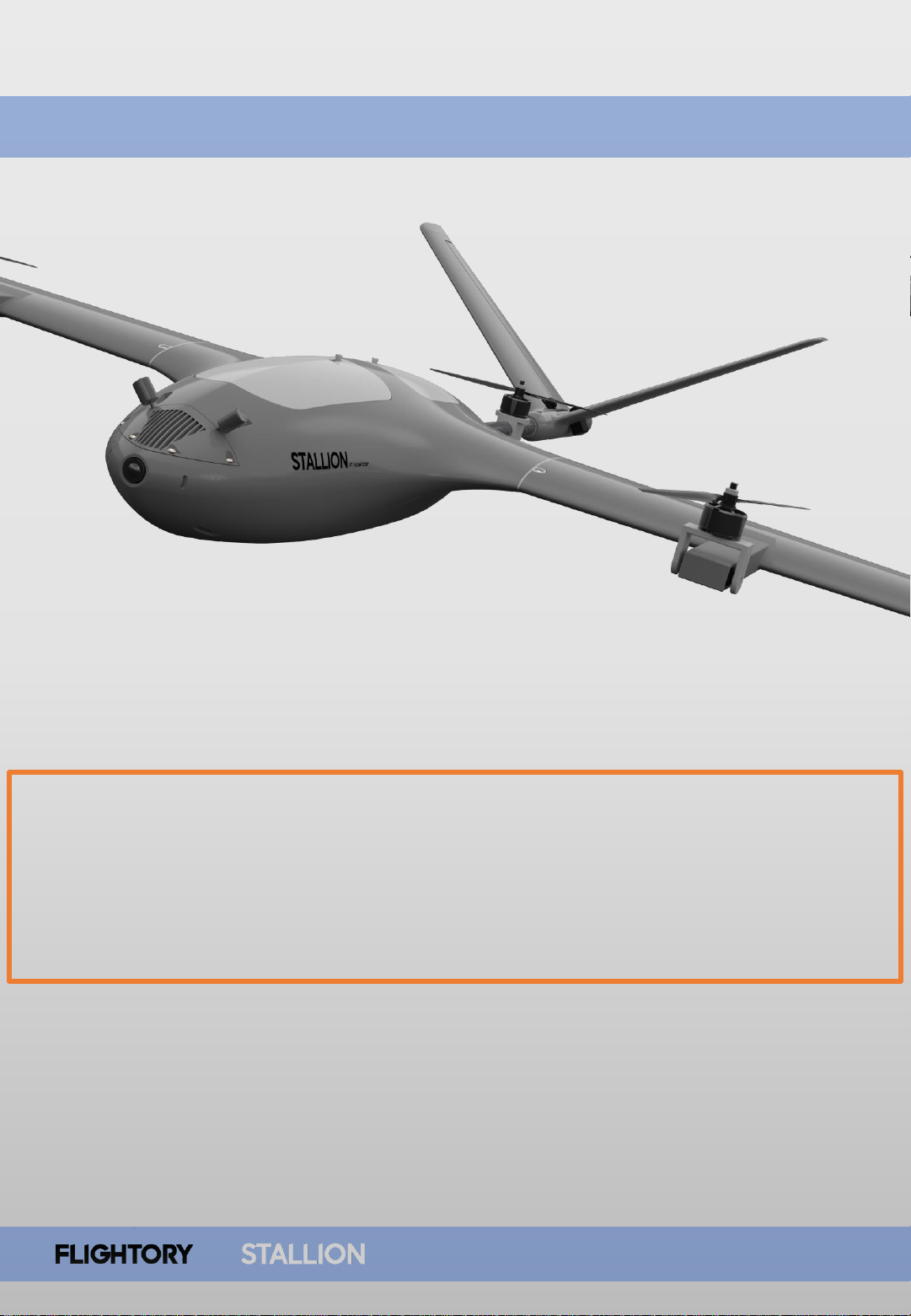
The build of this aircraft requires owning the basic version of the Stallion.
Modification for VTOL requires reprinting the wings along with all motor
mounting components. This instruction manual presents conversion to VTOL
version. If you are starting to build the aircraft from scratch, refer to the
manual for the regular Stallion, which details the construction of the entire
aircraft.
Page 4
General Aircraft Data
USER MANUAL
4
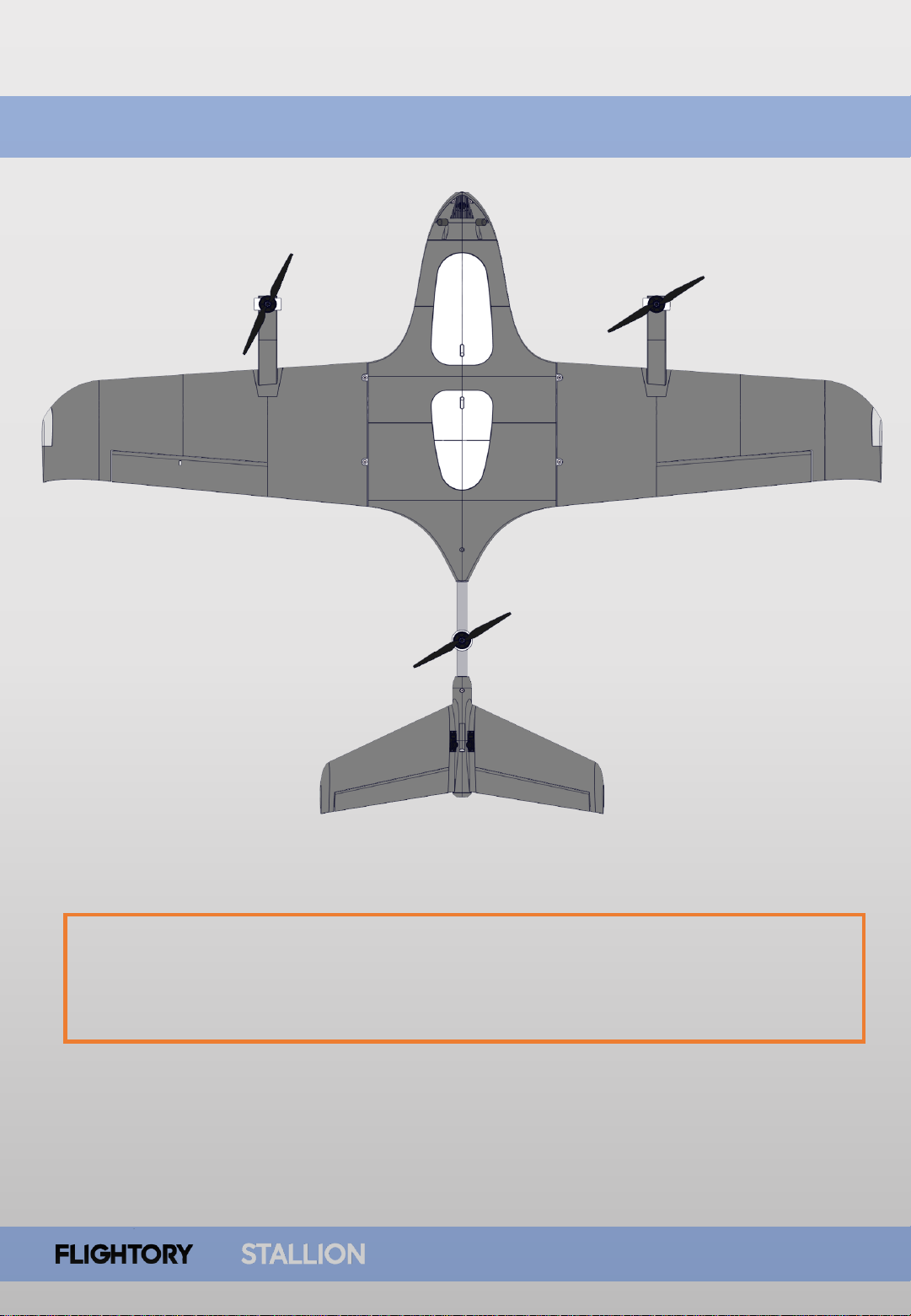
The aircraft is in the classic trimotor configuration with front tilt motors and one
rear fixed motor. Yaw in hover mode is controlled by tilting the front motors.
The rest of the aircraft's geometry remains unchanged from the regular Stallion
version.
Page 5

PARTS LIST - VTOL
USER MANUAL
5
PART MATERIAL
BOOM L /R
PETG
MOTOR MOUNT FRONT
PETG
MOTOR MOUNT TAIL
PETG
WING 1 L/R VTOL
LW-PLA
WING 2 L/R VTOL
LW-PLA
WING 3 L/R VTOL
LW-PLA
If you have access to a printer capable of printing at high temperatures
around 300°C you may also consider printing with materials containing
carbon fiber additives instead of regular PETG, which will further
reinforce the components.
Page 6

Reccomended Accessories and
RC Equipment
USER MANUAL
6
Reccomended
electronics
Motors
Emax ECOII 2807 1300KV link / T- Motor F90 1300KV link
Propellers
7x4 / 7x5 / 7x6 (two CCW, one CW) link
Servos
2pcs PowerHD 1810MG link / GDW DS041MG link
ESC
3pcs Emax Formula Series 45A BLHeli32 link / Lumenier 51A link
Battery
4S (max 4S3P 10,5Ah Li-Ion) or similar LiPo
Bearings
2pcs 3x8x4mm Flange Bearing link
Screws
/ Nuts /
Washers
3 pcs M3 Screws, Nuts and Washers
Page 7
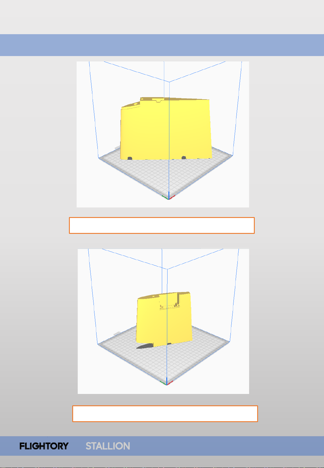
Parts Orientation
USER MANUAL
7
WING 1 L/R VTOL - 3% cubic subdivision infill
WING 2 L/R VTOL - 3% cubic subdivision infill
Page 8
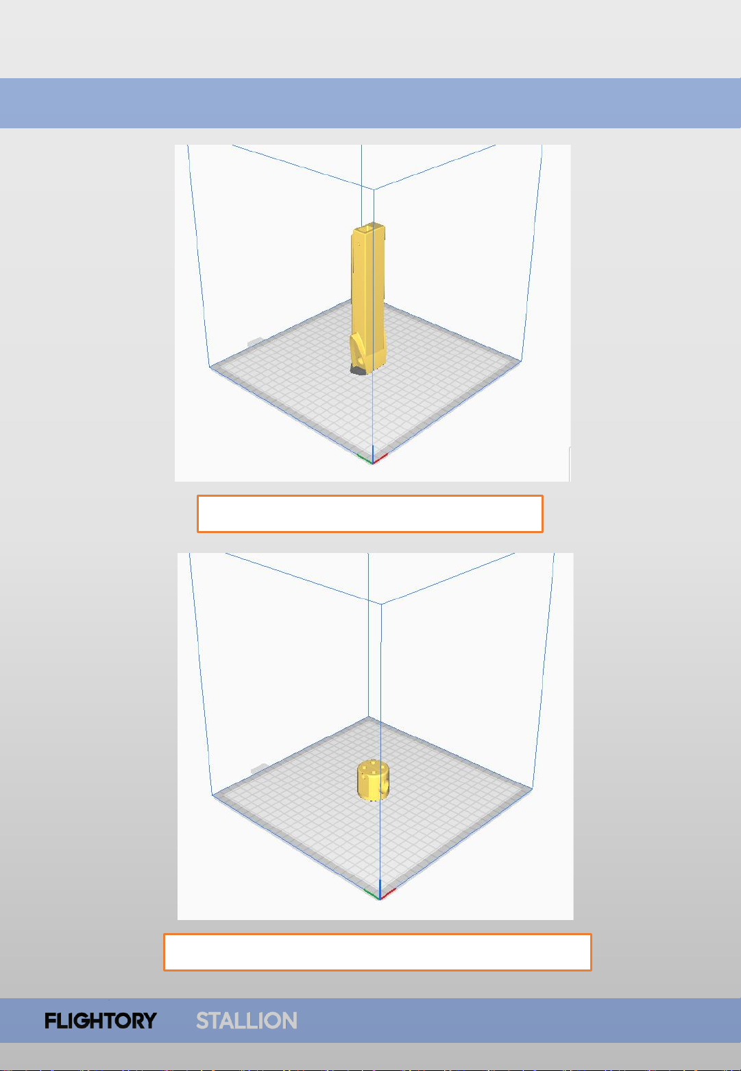
Parts Orientation
USER MANUAL
8
BOOM L/R – 3 walls, 20% cubic infill
MOTOR MOUNT TAIL 3 walls, 20% cubic infill
Page 9
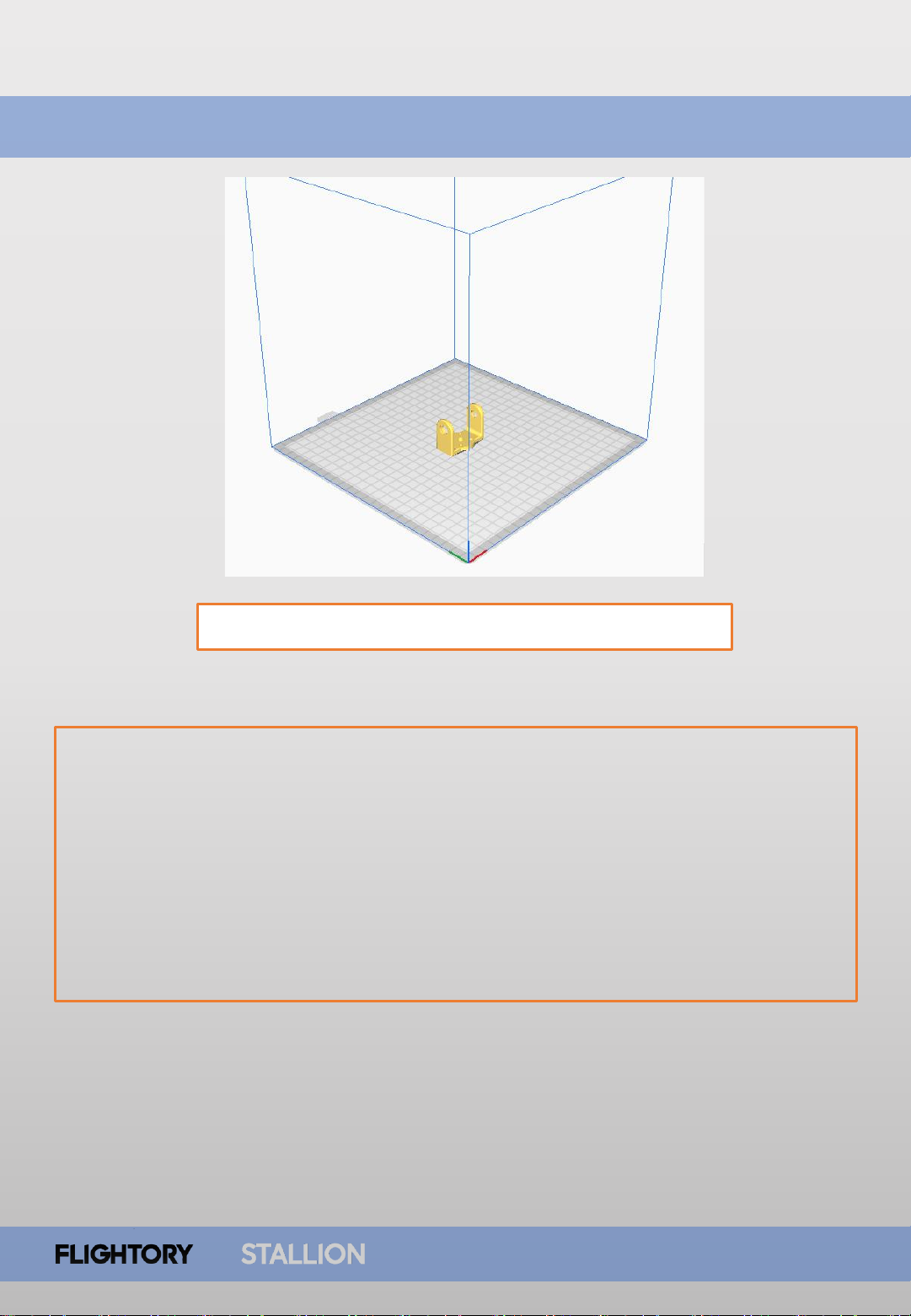
Parts Orientation
USER MANUAL
9
MOTOR MOUNT FRONT- 100% infill solid print
This component is particularly exposed to loads and vibrations.
It requires printing with full infill. Additionally, I recommend reinforcing
this part further. A simple and quick way is to acquire a small sheet
of thin fiberglass cloth and a small amount of epoxy resin. It's best
to cut several small pieces and place them on the inner side of this
element, paying particular attention to critical areas, and laminate
them with resin. Mounts prepared in this way have passed tests
successfully and can be used in flight without issues.
Page 10
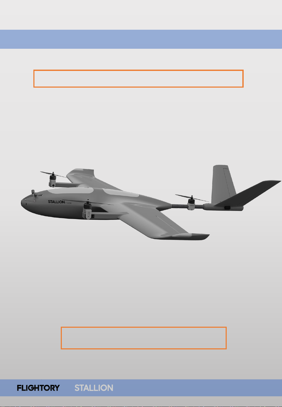
STL AND STEP FILES
USER MANUAL
10
All files in VTOL PACK are available in STL and STEP format.
You can find these files in folders labeled STEP
Page 11
Tail Motor Assembly
USER MANUAL
11
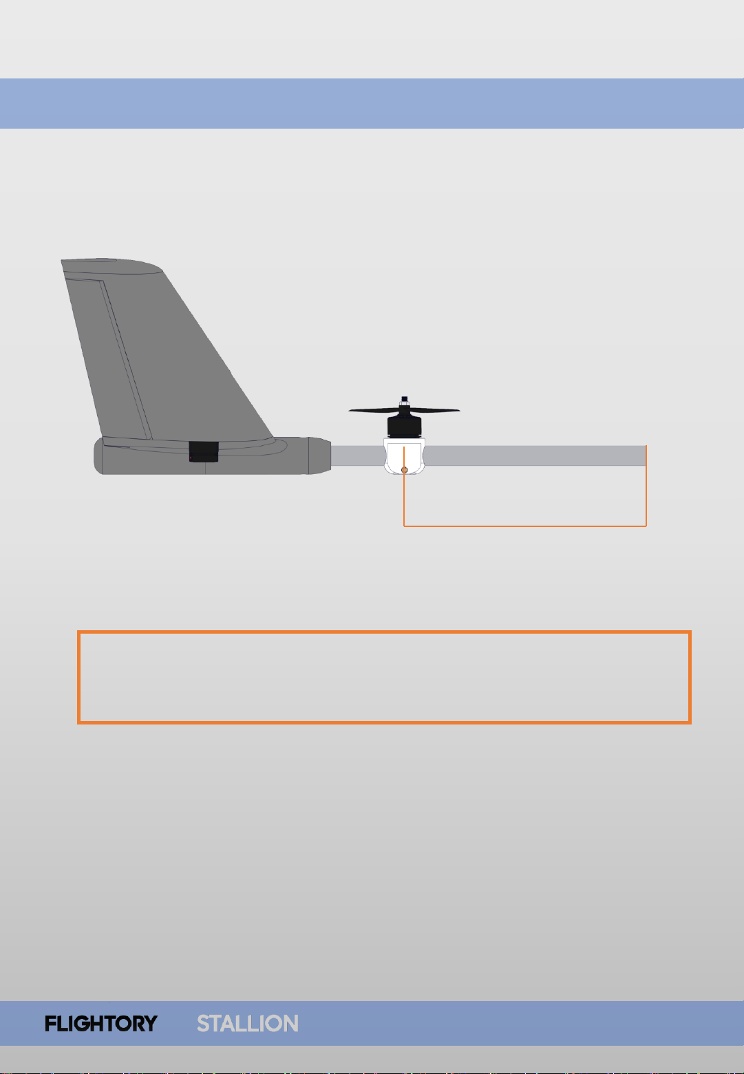
To mount the tail motor, you'll need to remove the tail boom.
The correct positioning of the motor is as shown in the diagram.
The motor shaft should be located 195mm from the front end of the tube.
195mm
Page 12
Tail Motor Assembly
USER MANUAL
12
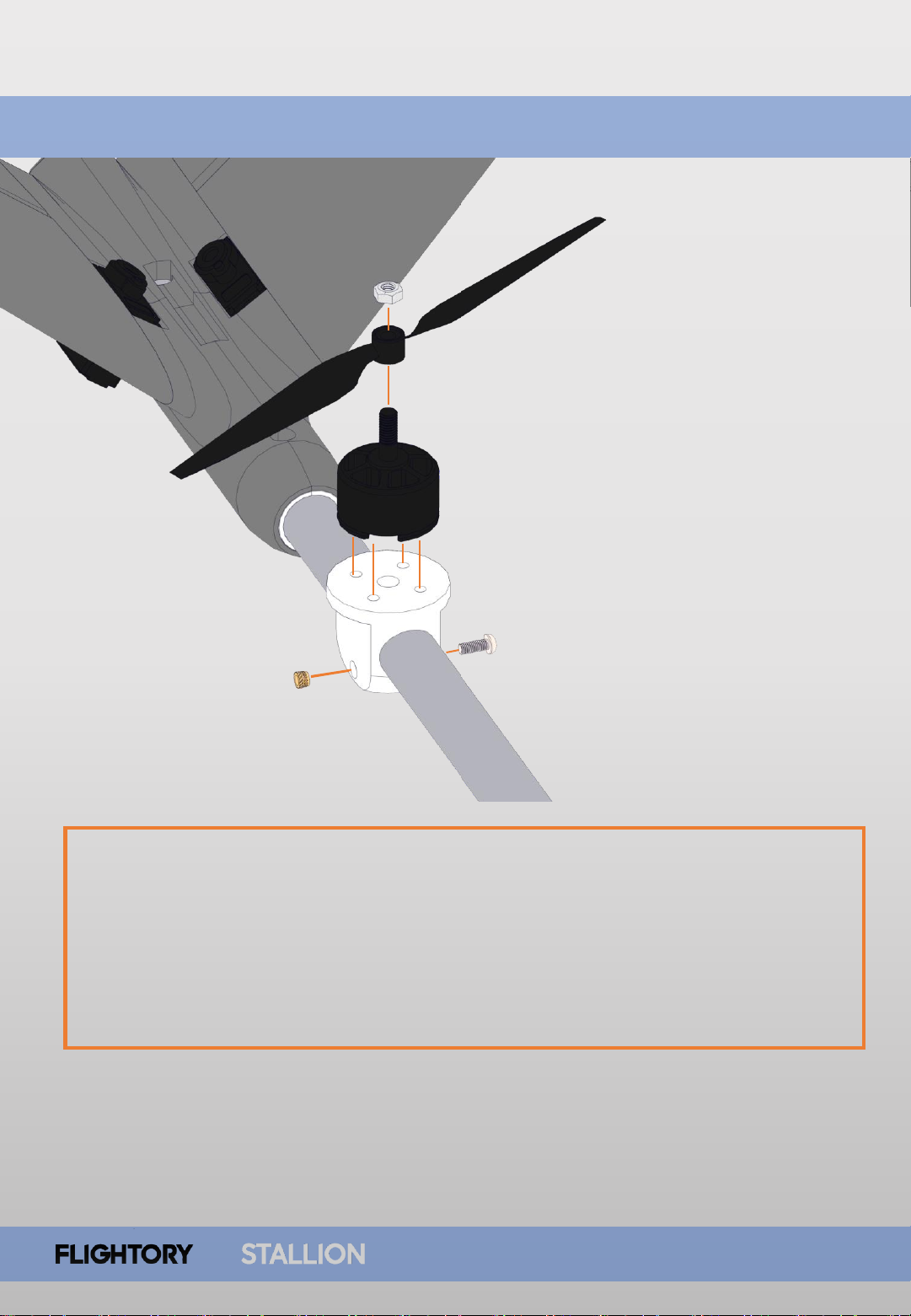
Take the MOTOR MOUNT TAIL and screw the motor onto it. To mount it, you
slide it onto the tailboom. Press the M3 threaded insert from one side and insert
the M3 screw from the other side. Align the motor properly and tighten the
mount on the tail boom to make it stiff and immobile. You’ll need to cut a small
hole through which you'll route the motor cables inside the boom to the
fuselage. You can do this with a drill or, for example, a Dremel cutting tool or
similar.
Page 13
Tail Motor Assembly
USER MANUAL
13
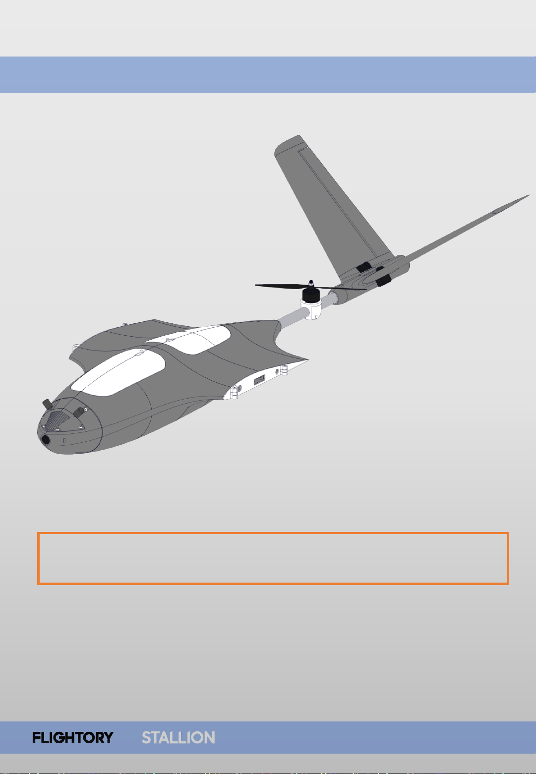
You can now slide the tail boom into the fuselage and secure it with the M3
screw as usual.
Page 14
Front Boom Assembly
USER MANUAL
14
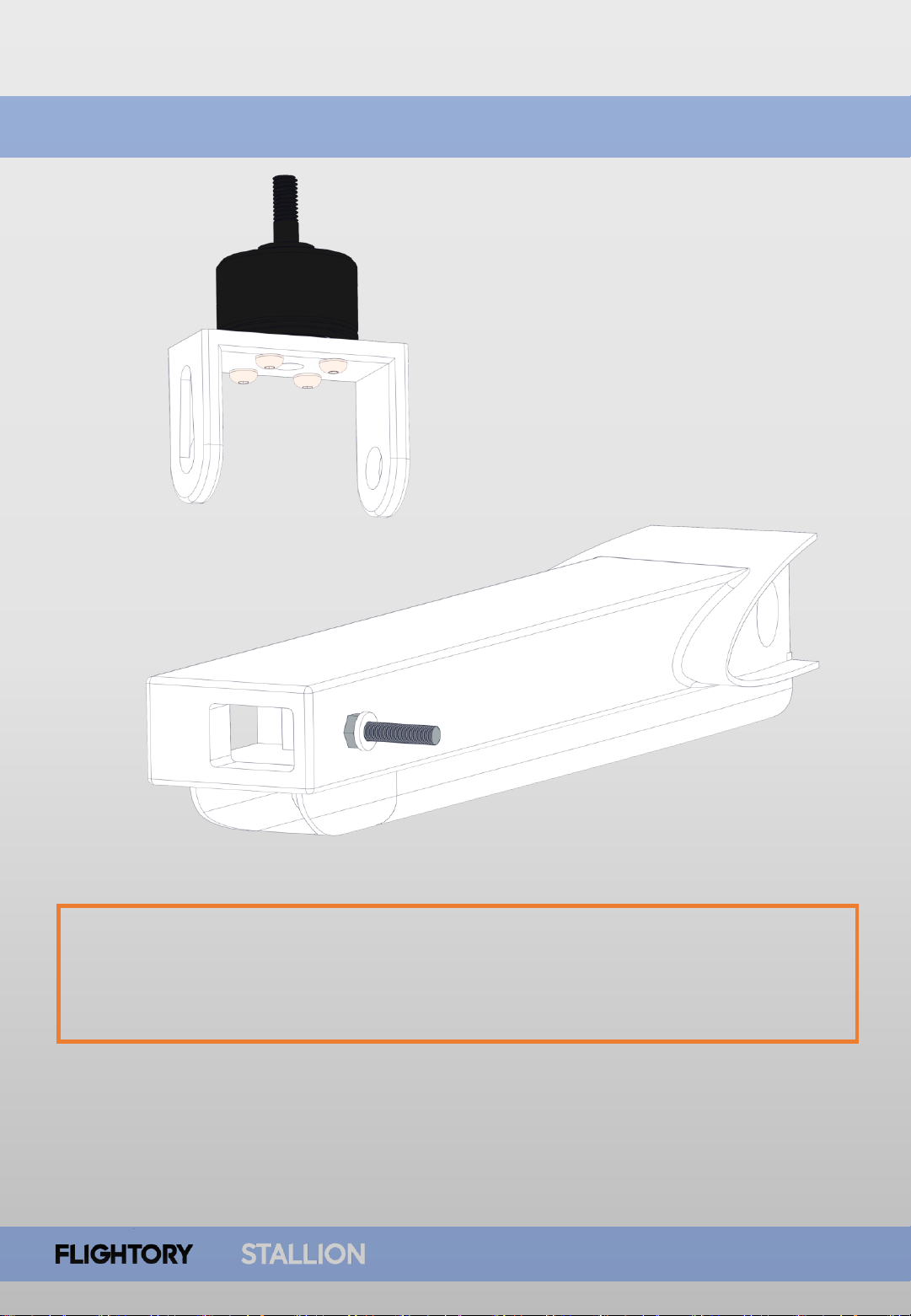
To start, screw the motor onto the MOTOR MOUNT FRONT. At this stage, also
screw in the M3 screw from the inside of the BOOM as shown in the drawing.
Secure it tightly with a nut from the outside. Finally, place a washer.
The screw should be about 15mm long.
Page 15
Front Boom Assembly
USER MANUAL
15
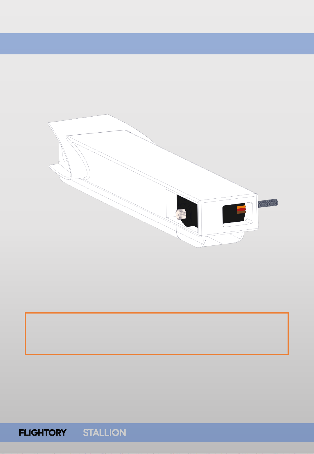
Next, insert the servo into the designated slot and secure it with the small
screws that should be included in the servo package. Route the cables
through the channel running underneath.
Page 16
Front Boom Assembly
USER MANUAL
16
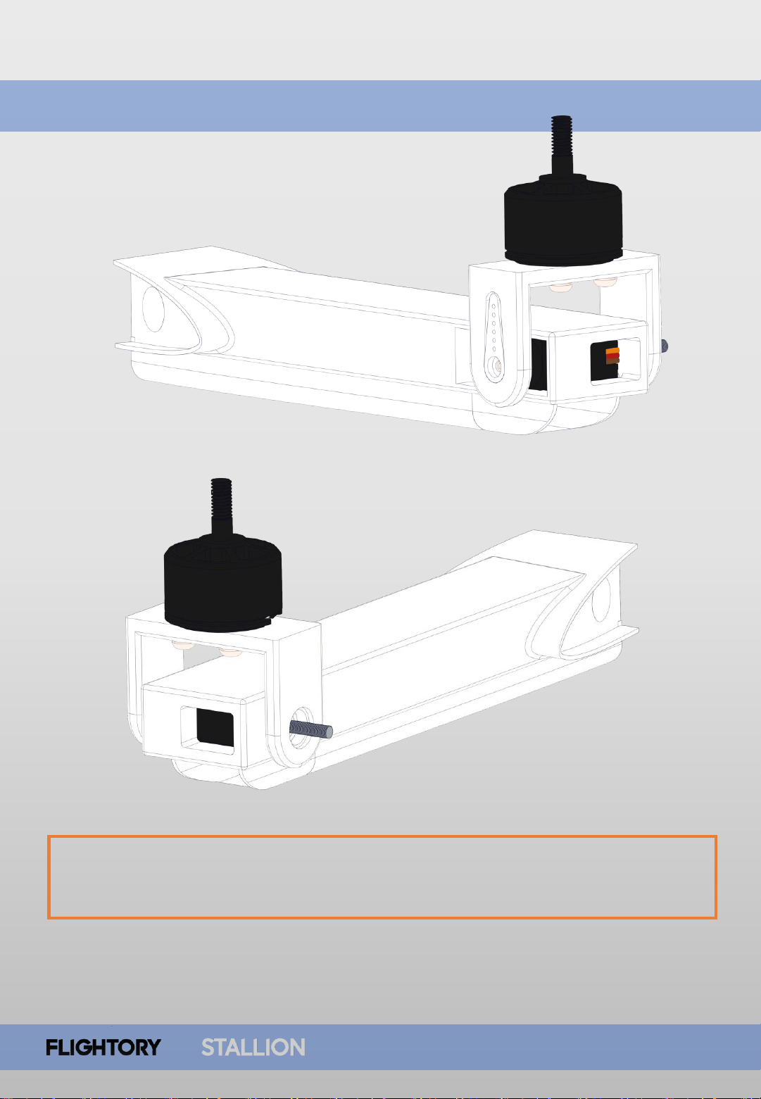
Now, place the motor in the manner shown in the drawing. Insert the servo
horn, which secures the assembly from one side. Route the motor cables directly
into the lower channel.
Page 17
Front Boom Assembly
USER MANUAL
17
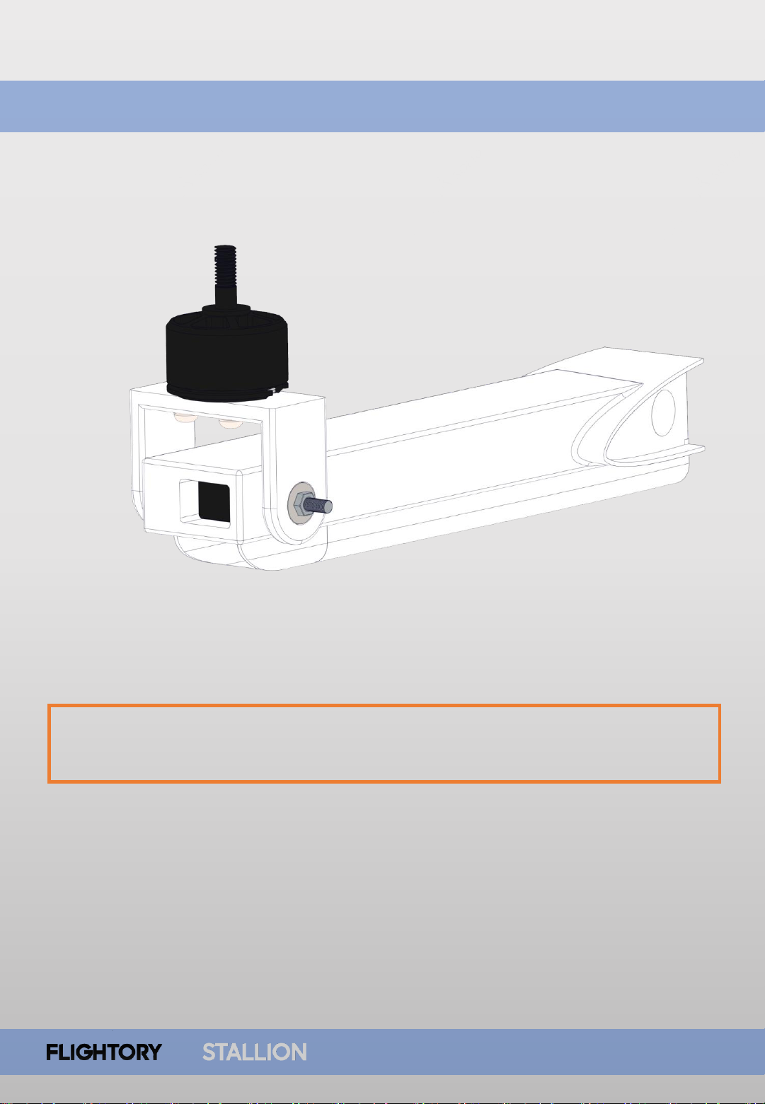
Now, on the other side, insert the 3x8x4mm bearing and finally secure it with an
M3 nut. This ultimately stabilizes the mounting and ensures smooth movement.
Page 18
Wing Assembly
USER MANUAL
18
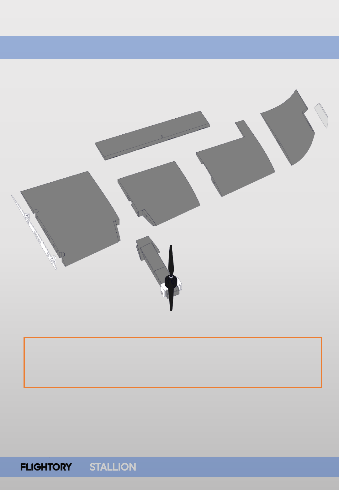
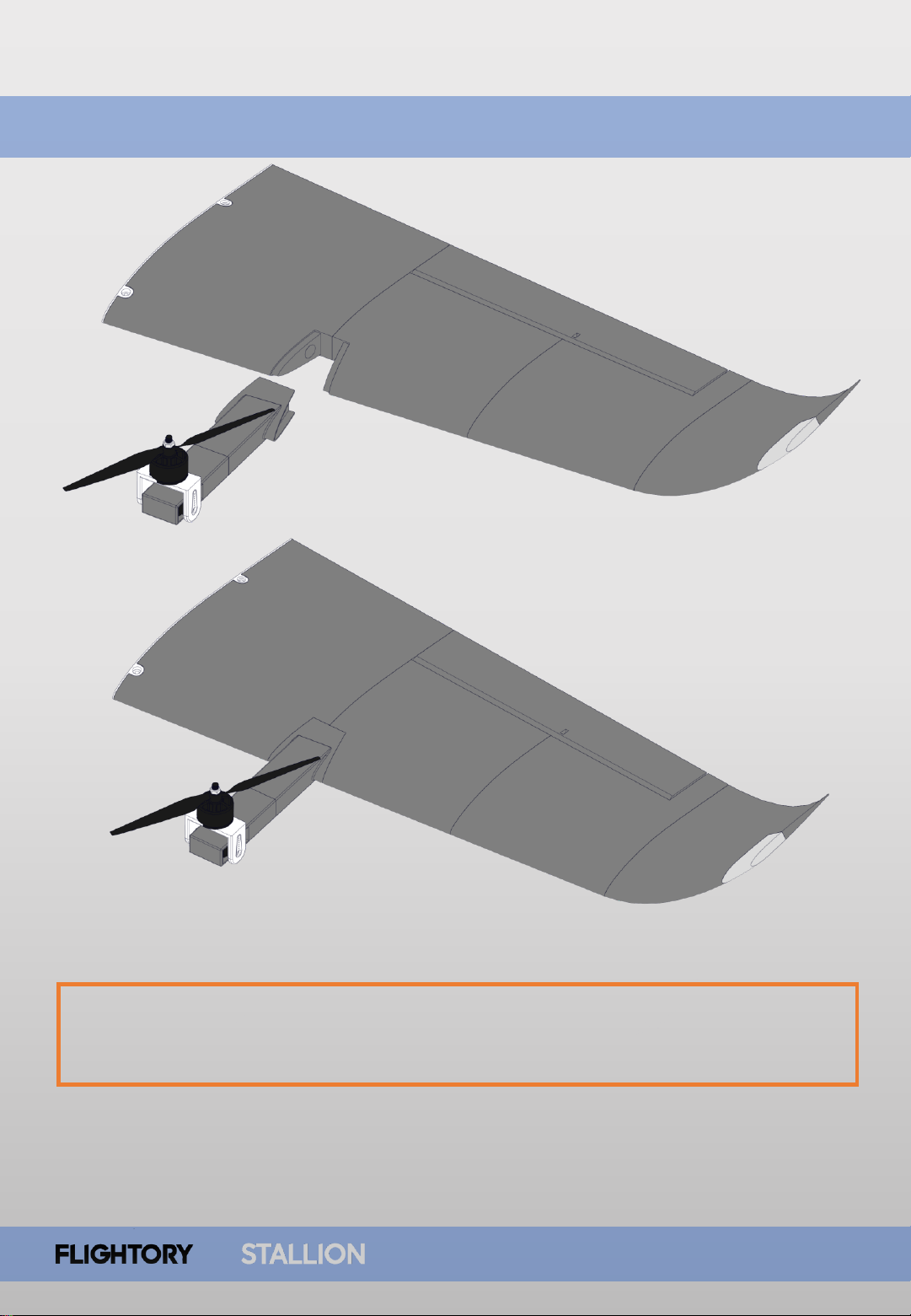
Now, assemble the entire wing. The assembly process is almost identical to the
basic version of the Stallion. Only segments 1 and 2 of the wing have designated
place for mounting the motor boom. Segment 3 is the same, and you can also
choose whether to mount the LED or not.
Page 19
Wing Assembly
USER MANUAL
19
After assembling the wing, firmly glue the Boom in place using CA glue, making
sure to do it evenly. Note that when mounting the wing to the fuselage, the
main spar will also pass through the Boom, further reinforcing the structure.
Page 20
Wing Assembly
USER MANUAL
20
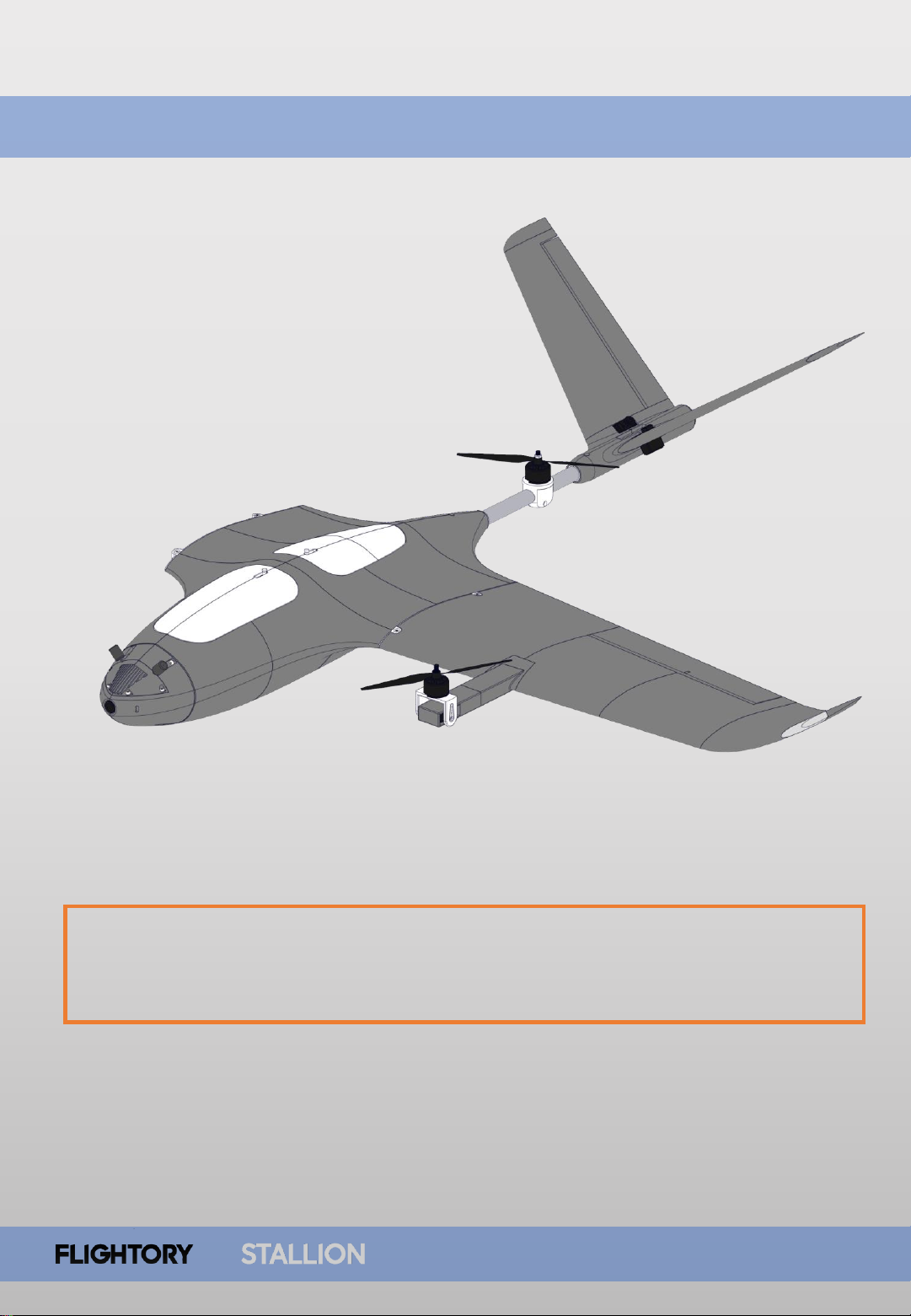
Now insert the wings and route all the cables from the motor and servo to the
channel in the wing that leads to the fuselage. Repeat the same process with the
second wing.
Page 21
Finishing Build
USER MANUAL
21
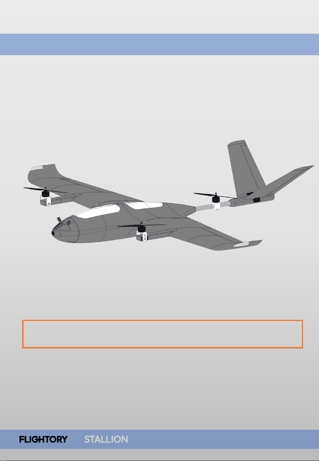
At this stage, the entire structure is now ready, and it's time to move on to
connecting cables and configuration
Page 22
Configuration
USER MANUAL
22
The software I recommend is Ardupilot. It's necessary to familiarize yourself with
the information on the website where the full configuration of Tiltrotor Planes in
Ardupilot is described.
https://ardupilot.org/plane/docs/guide-tilt-rotor.html
I will present here the most important information and parameters that need to
be set and paid attention to.
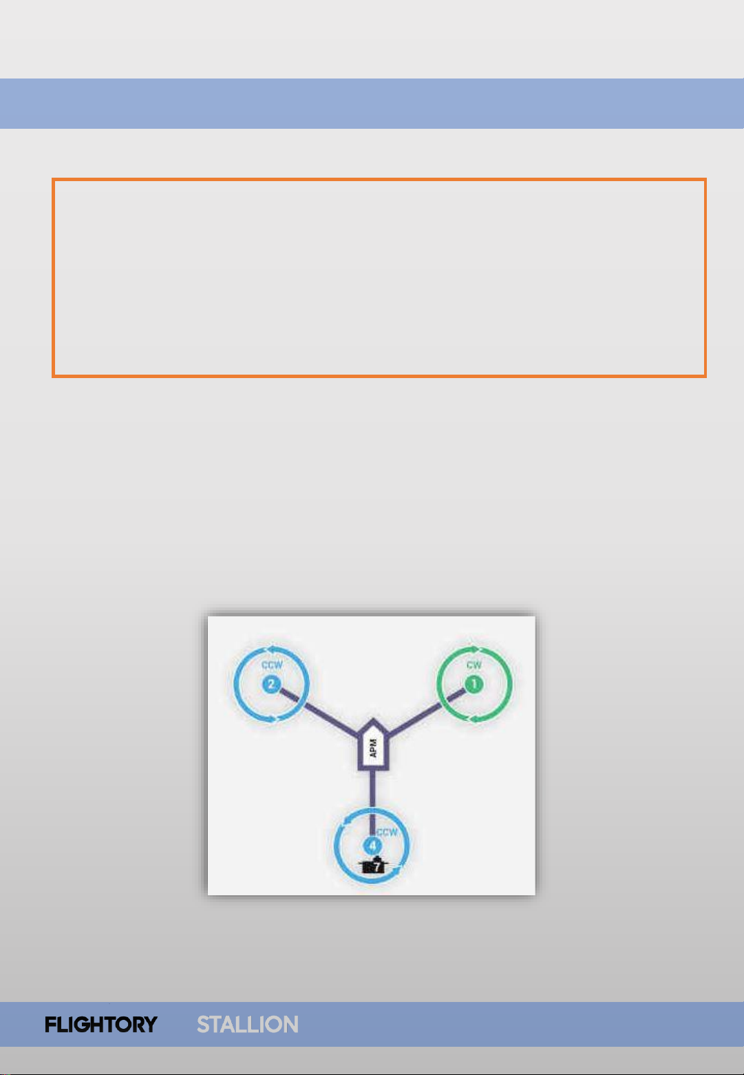
Tricopter Configuration
Stallion is a tricopter aircraft with two front tilt motors and one fixed rear motor.
Yaw control is achieved by tilting the front motors. We select the option with
front propellers CW and CCW. In the diagram, you can see the numbering of the
motors, and this is how they should be numbered in Mission Planner.
Page 23
Configuration
USER MANUAL
23
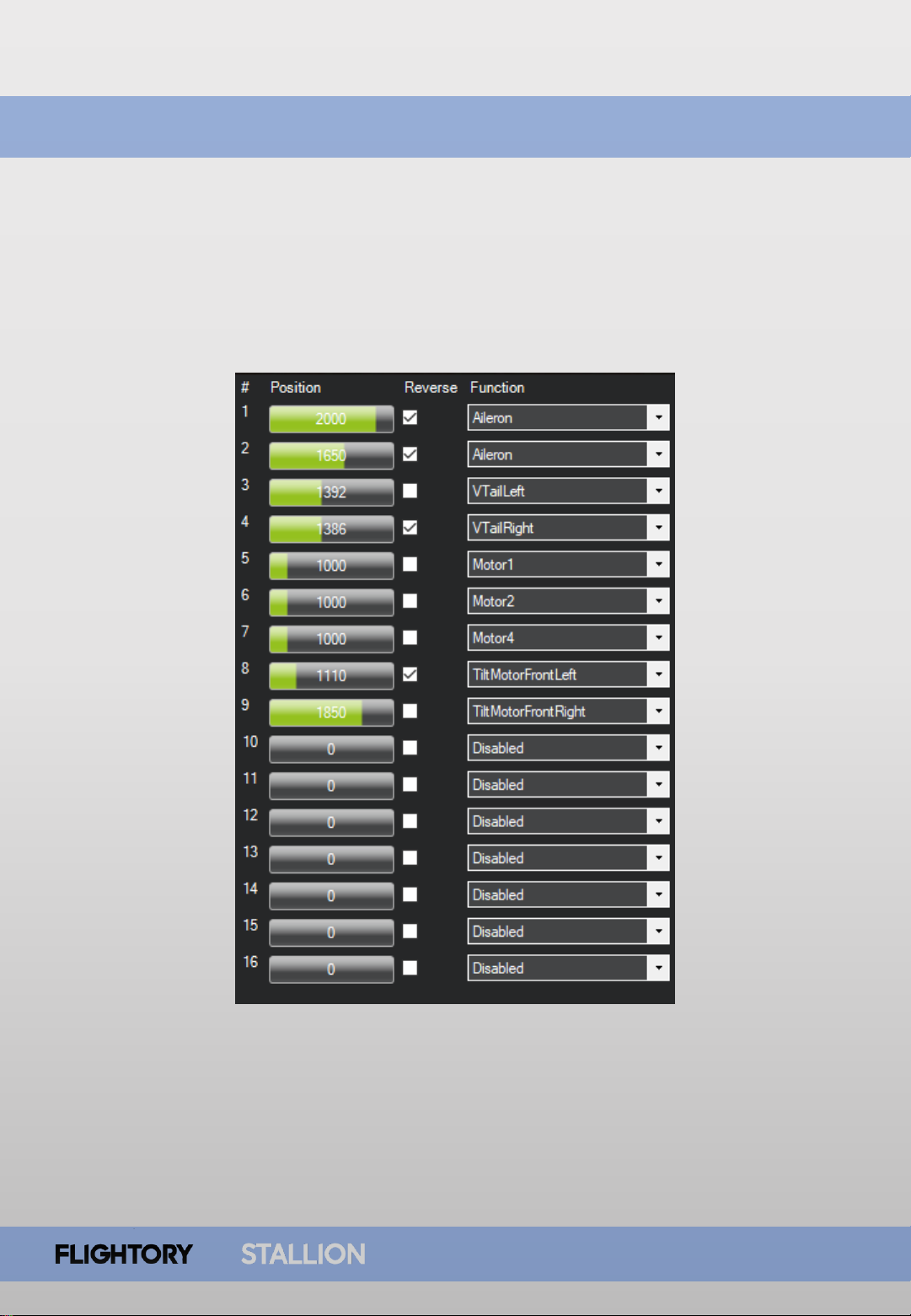
Servo Output
This is the assignment of all channels that you can set at the beginning.
Page 24

Configuration
USER MANUAL
24
Q_ENABLE = 1
Next, you need to set the parameter Q_ENABLE to 1. This enables all options
related to quadplane support. You need to click ‚write’ and then ‚refresh’
to obtain the full list of parameters.
Q_TILT_ENABLE = 1
MAIN TILT ROTOR PARAMETERS
Also set Q_TILT_ENABLE to 1, indicating the use of tilt motors.
Q_FRAME_CLASS = 7
Next, set Q_FRAME_CLASS to 7, indicating the selection of the tricopter layout
Q_TILT_MASK = 3
The next step is to set the parameter Q_TILT_MASK to 3. It specifies which
motors are to tilt. The number is determined by adding the numbers of the
motors together. In our case, the front motors are labeled 1 and 2, so 1+2=3.
Q_TILT_TYPE = 2
By setting Q_TILT_TYPE to 2, this parameter specifies the tilt type as vectored.
This means that yaw in Hover mode will be controlled by tilting the front motors.
Q_TILT_YAW_ANGLE = 15
You need to specify the maximum tilt angle of the motors during yaw
operations. Setting it to 15 degrees is suitable for the Stallion, meaning that the
motor can tilt up to 15 degrees beyond its neutral vertical position when
controlling the yaw channel. You can adjust this value to be higher or lower
depending on how responsive you want the aircraft to be on the yaw.
Q_TILT_MAX = 45
This parameter specifies the tilt angle of the motors during transition. In this
position, the motors will be during waiting for the required horizontal flight
speed. 45 degrees is the default value and is good, no change required.
Page 25

Configuration
USER MANUAL
25
Q_TILT_RATE_UP = 15
This parameter determines how quickly the motors will tilt during transition and
is expressed in degrees per second. 15 degrees means that a full transition will
take 6 seconds and is a good value for the Stallion, ensuring smooth transition.
You can separately set Q_TILT_RATE_DN, which is the speed of tilting the motors
downwards. It is by default set to 0, and I recommend leaving it as such, as then
the value of 15 degrees is applied for both directions.
MAIN TILT ROTOR PARAMETERS
Q_ASSIST_SPEED = -1
Determines the speed below which the tilt motors will assist in generating lift.
This can be seen as an additional safeguard against stalling, where the motors
will automatically tilt upwards. However, we do not want this function in this
aircraft, so we set it to -1 to disable it.
Q_M_PWM_TYPE = 7
Specifies the PWM type for the motors. If you are using the recommended ESCs,
they support DSHOT1200, and the value of the parameter should be set to 7.
This is a useful feature that allows you to bypass manual ESC calibration.
Q_OPTIONS = 163841
This parameter allows you to set additional options. You can manually select the
functions you are interested in, and the parameter value will adjust
automatically. By selecting the recommended options, the value comes out to
be 163841.
Select the functions: Level Transition (Maintains wings level within the
LEVEL_ROLL_LIMIT range during transition), ThrLandControl (Allows manual
throttle control during landing), EnableLandReposition (Allows manual position
adjustment during automatic landing).
Page 26

Configuration
USER MANUAL
26
ARSPD_FBW_MIN = 12
ARSPD_FBW_MAX = 25
These parameters specify the minimum and maximum speed in m/s in
automatic throttle modes. The values align well with the characteristics of the
Stallion. The minimum speed is crucial during transitions. Full transition will be
executed upon reaching the minimum flight speed.
MAIN TILT ROTOR PARAMETERS
Q_TRANSITION_MS = 7000
Q_TRANSITION is related to the previous one and determines the time in
milliseconds for a full transition after reaching the minimum speed. During this
time, the front motors gradually transition fully to horizontal flight, while the
rear motor shuts off. Seven seconds ensure a smooth transition without the risk
of losing lift and altitude.
Q_LAND_SPEED = 20
The descent rate in Q_LAND mode. The value is expressed in cm/s. 20 ensures a
gentle descent. After touching the ground, for a few seconds, the lack of altitude
change is detected, and shortly after, the motors switch to disarmed mode.
Q_M_BAT_VOLT_MAX = 16.8
Q_M_BAT_VOLT_MIN = 13.2
These parameters determines the maximum and minimum battery voltage
values. When using 4S packs, you should enter the above values. This allows
compensation of throttle in hover mode depending on the current battery state.
This way, the throttle position should always provide the same thrust regardless
of the voltage.
Page 27

Configuration
USER MANUAL
27
After setting all the mentioned parameters, the aircraft is ready for its first flight
tests. However, I strongly encourage you to familiarize yourself with the entire
chapter on quadplanes on the Ardupilot website. You will find a lot of
information there regarding configuration and tuning, flight mode operations,
and much more.
FLIGHT MODES
https://ardupilot.org/plane/docs/qua
dplane-flight-modes.html
FLYING A QUADPLANE
https://ardupilot.org/plane/docs/qua
dplane-flying.html
VTOL TUNING
https://ardupilot.org/plane/docs/qua
dplane-first-flight.html
QUADPLANE SETUP TIPS
https://ardupilot.org/plane/docs/qua
dplane-tips.html
QUADPLANE GENERAL CHAPTER
https://ardupilot.org/plane/docs/qua
dplane-setup.html
IMPORTANT SUBSECTIONS
Page 28
28
USER MANUAL
 Loading...