

Page 1

flight of harmony
POWER Barebones Pack
~v1.0~
Page 2
+
+
+
+
g.1 g.2
Components
1
Assembled POWER PCB
1*
12VAC 1000mA wall adapter
1
13” 18AWG DC power harness
1
DPDT power switch with hardware
1
2.1mm x 5.5mm x 9.5mm barrel-style AC jack with hardware
1
MTA156 4-pin 22AWG IDC connector (switch)
1
MTA156 2-pin 22AWG IDC connector (AC jack)
1
Red 5mm LED (V+)
1
Yellow 5mm LED (V-)
2
Molex SL-series 0.1” 2-pin housing (PCB end)
2
Molex SL-series 0.1” crimp terminals (PCB end)
2
Molex KK-series 0.1” 2-pin housing (LED end)
4
Molex KK-series 0.1” crimp terminals (LED end)
* Only part of standard PWBP
2/7
Page 3

Specications
Module width 10 h.p.
Input voltage 12VAC
Maximum current output
Output voltage
IV+= 1A IV-= -1A
±12VDC
What is it?
This one is pretty straightforward: a power supply for your modular
synthesizer rig. No sweet spots, no easter eggs, it just makes juice.
POWER was designed with portable racks in mind –– shallow depth,
reduced weight, and keeping the mains transformer outside of the case to eliminate
related noise and heat –– but it can be used to supply any compatible system.
Usage
The standard AC wall adapter (if you purchased the standard unit) is
rated for 1 Ampere (A. K. A. 1 Amp, 1A, 1000mA), as is the POWER module
itself. For best performance – and this applies to ALL electronics, by the way – you
should never run POWER at its maximum rating. A 60% load (600mA) is the
practical limit for best performance.
If you need/want to run it up to 75% or 80%, a greater capacity
adapter is needed to maintain performance. Adapters get hotter as more power
is drawn from them, which increases the internal resistance and thusly reduces the
performance. A 1500mA rated adapter is recommended.
The adapter plug must be a 2.1mm x 5.5mm x 9.5mm barrel-type plug.
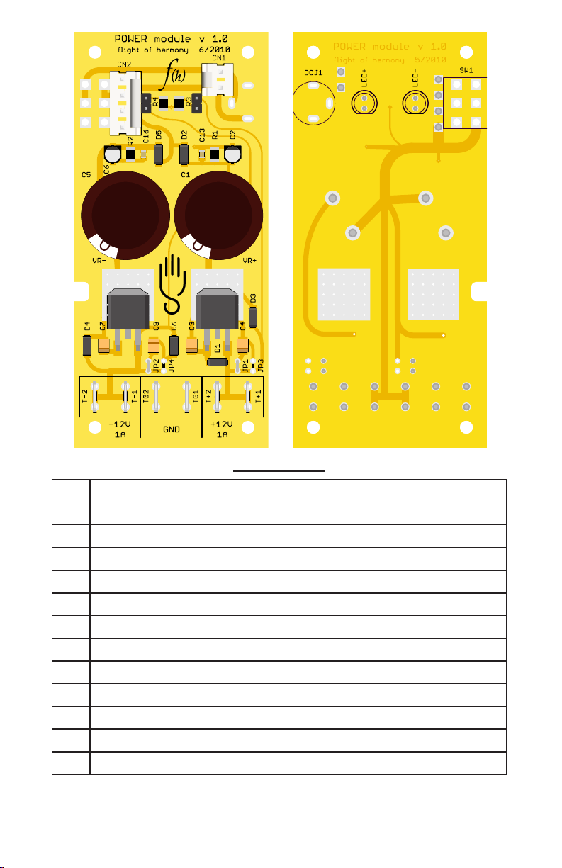
Input Connections
AC jack: CN1 is for the AC adapter jack. Tip wire to the top pin, sleeve
wire to the bottom pin (as shown in g. 1).
Power switch: CN2 is for the power switch. When the switch is turned
ON, pin 1 is connected to pin 4, pin 2 is connected to pin 3.
Output Connections
LED+: From the front side, this is the header next to R3 and is the +12V
LED (red). Anode (longest leg of the LED) to the top, cathode (shortest leg of the
LED) to the bottom.
LED–: From the front side, this is the header next to R4 and is the -12V LED
(yellow). Anode (longest leg of the LED) to the top, cathode (shortest leg of the LED)
to the bottom.
3/7
Page 4

IMPORTANT
The LEDs are required for stable operation
at low levels of current draw.
This means they must be attached, even if you do not plan to panel-mount
them. Just put them on short leads (or even just solder them to the headers).
Power Connections
The power output connectors are standard 0.25” width male quick-connect
terminals, compatible with the standard Doepfer PSU harnesses and distribution
board terminals.
T+1 & T+2: +12V
T-1 & T-2: -12V
TG1 & TG2: System ground
Compensation jumpers
Power supplies are infamous for mysteriously becoming unstable.
Their performance is dependent upon the type of load they are powering, and
no two systems are the same. As I have dealt with this sort of problem in the past,
there are provisions on the PCB to adjust the regulator output capacitors to tailor
output performance to your specic load characteristics.
The existing jumpers – JP1(V+) & JP2(V-) – bypass these provisions, and
are required for normal operation. The positions marked JP3 & JP4 are connected
in parallel with C4 and C8, respectively, and can be used to increase the
regulator output capacitance. Cut JP1 or JP2 as necessary to reduce the output
capacitance.
4/7
Page 5

Anode
Cathode
Flat
Slot
On
O
Off
Common
On
1 - Pin
2 - Switch (not connected)
3 - Sleeve
1
3
2
Power switch connection
AC input jack connection
LED connection
5/7
Page 6
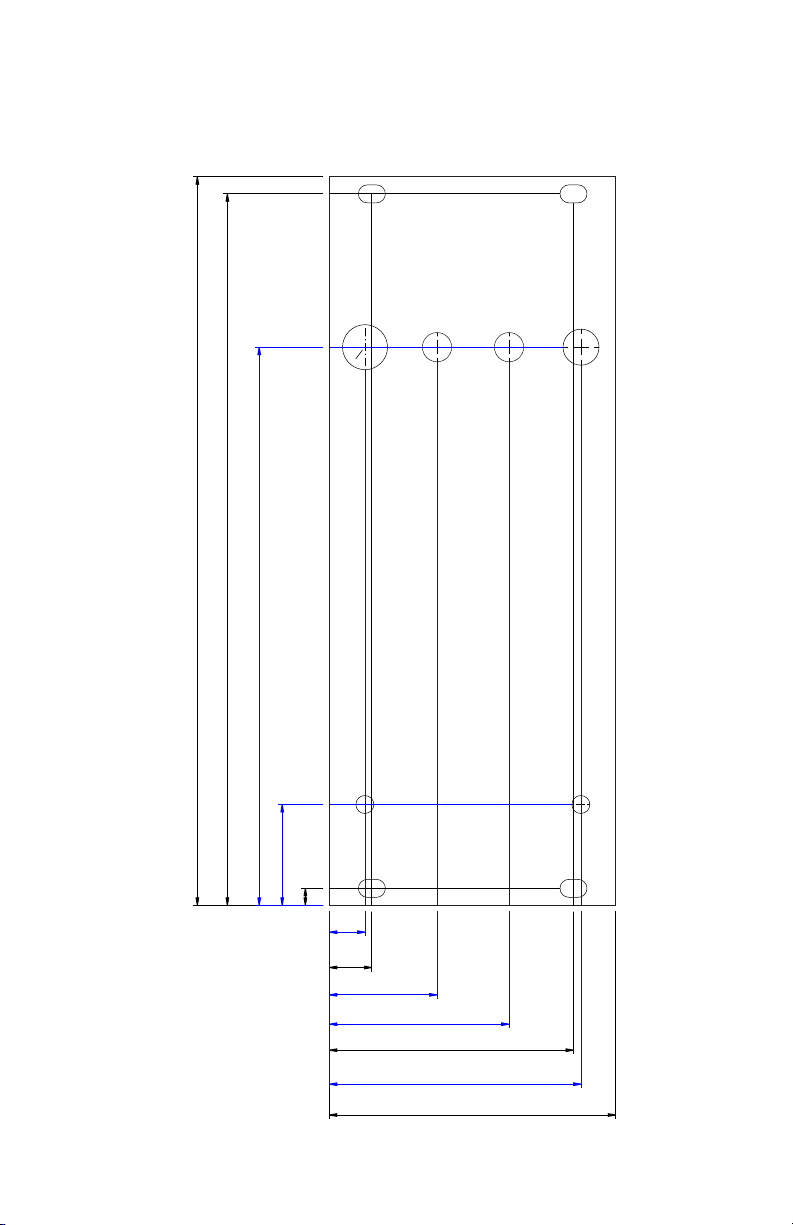
ø0.25”
ø “
5
16
13/64”
13/64”
ø0.125”
ø0.125”
1.988"
0.118"
0.295"
1.695"
5.059"
4.941"
0.248"
0.748"
1.248"
1.748"
0.700"
3.876"
Panel template
6/7
Page 7
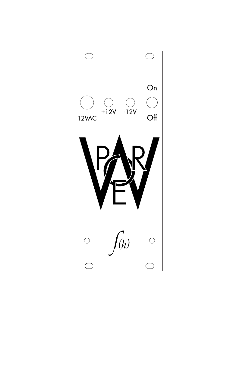
Graphics
7/7
Page 8

Stuff
come check it out! People have posted some excellent examples on there. I haunt
the forums as well, and new things are posted there long before they hit the f(h)
web site.
A big thank you to those who have sent in suggestions and comments,
keep them coming!
Send samples to: samples@ightofharmony.com
Comments, suggestions, complaints to: ight@ightofharmony.com
Drawings and designs ©2010 ight of harmony / Red Hand Studios
There is a lot of discussion about POWER on the Muffwiggler forums,
http://www.muffwiggler.com/forum/index.php
http://www.ightofharmony.com
Revised Aug, 2010. (rst printing)
f(h)
8/8
 Loading...