

Flight Model YAK-55 50CC Assembly Manual

CAUTION : this plane is not a toy!
Before use , please carefully read this manual.
●First-time builders should seek advice from people having building
experience in order to assemble the model correctly and to produce its
●Assemble this kit only in places out of children’s reach!
●Take enough safety percautions prior to operating this model.
You are responsible for this model’s assembly and safe operation!
●Always keep this instruction manual ready at hand for quick
reference,even after completing the assembly.
Length:85.5in/2172mm;
performance to full extent .
Radio:6Channel 6Servos;
Flying Weight:7300-7700g; Wing Span:86.6in/2200mm;
Wing Area:94sq.dm;
Engine:50CC Gas
Page1

●Make sure to apply Vaseline to
the rudder hinges to prevent the
epoxy from getting in to the joint.
●Make sure to allow room for
epoxy to penetrate the hinges.
Carefully slide the rudder onto
each hinge and against the trailin
g
edge of the fin.Wipe away excess
epoxy with alcohol wetted wipes.
●Ensure there is no gap
between fin and rudder.
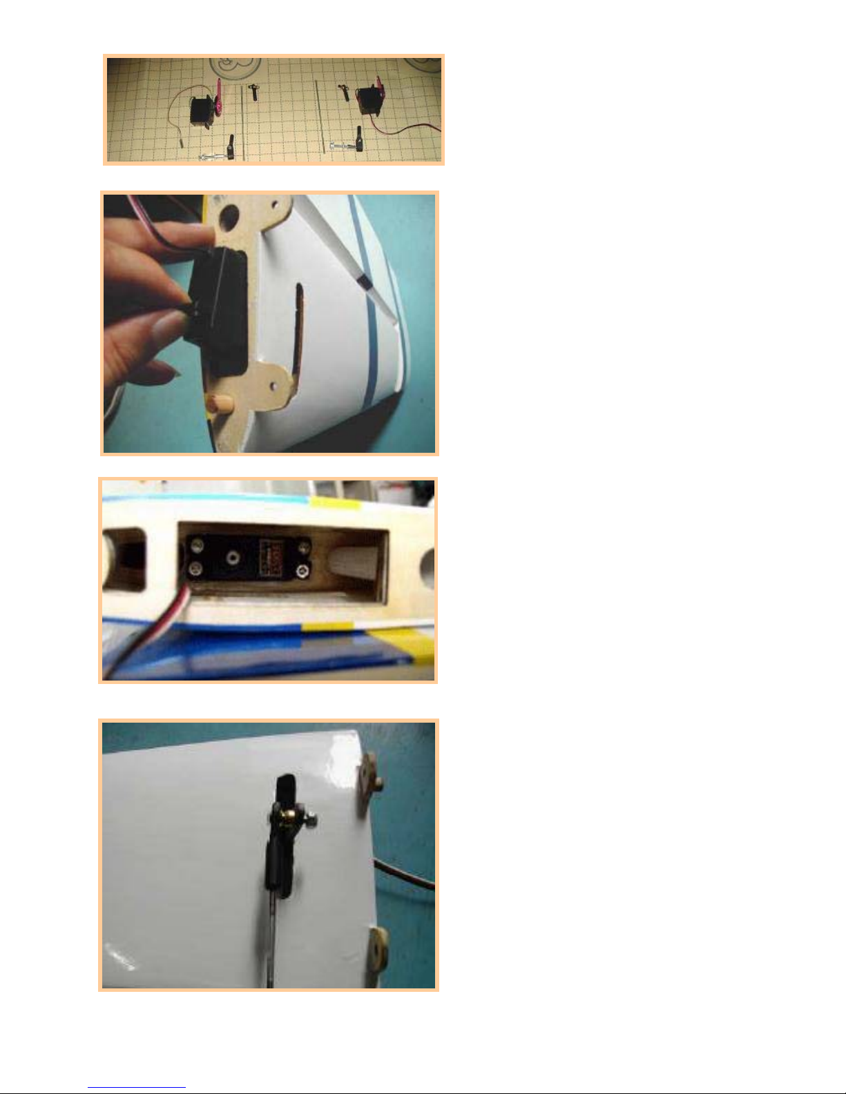
Install the rudder servo in the
fuselage that prepared by factory.
Feed the rudder cable through th
e
cable exit tube in the tail of the
fuse toward the front of the fuse.
Repeat on other side.
Adjust rudder pull-pull cables
to desied tension by screwing in
or out on the threaded couplers
and or ball links.Make all adjustments with the rudder servos still
powered up and centered,and th
e
rudder still taped in the neutral
position.
RUDDER AND TAIL WHEEL
Push
rods
Rudder
servo
Page2
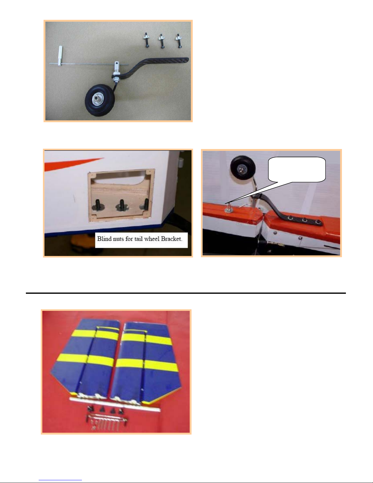
●Ensure the servo doesn't bind
at center or at either end point.
Drill holes in the hardwood tail
wheel mount and install the blind
nut through the opening in the
rear of the fuse.
Install the mounting screw for the
tail wheel.
●Ensure it has been totally
screwed into the blind nuts.
Install the hatch over the opening in the rear of the stabilizer with 4 screw
s
Mount the elevator onto the stab
making sure you use Vaseline in
the hinge points so the glue will
not stick the hinge shut.
Install the control horns in place
for the elevator horn before slidin
g
the stab in place.
Screw the threaded pushrod and
swivel in place onto the elevator
horn.Plug in a 24"servo wire
extension and use a securing clip
provided to make sure they don't
come unplugged in flight.
STABILIZER AND ELEVATOR
A
luminum
steering
Page3
Mount the elevator servo in place
and pull the servo wire extension
up toward the front.
Attach the servo extension wire
using foam wire holding brackes
or zip ties to the formers along
the sides of the fuse so they
can't interfere with the rudder
control cables.
Mount the servo arm on to the
elevator push rod before installin
g
it on the servo so you can tighten
the nylon insert locking nut to the
mounting screw.
Slide the stab on to the alumium
tube and attach to fuse using the
bolts provided.
●Make sure the bolts has been
totally screwed into the blind nuts
.
Page4
 Loading...