

Flight Medical Innovations Flight 60 Ventilator Operator's Manual
FLIGHT MEDICAL INNOVATIONS LTD.
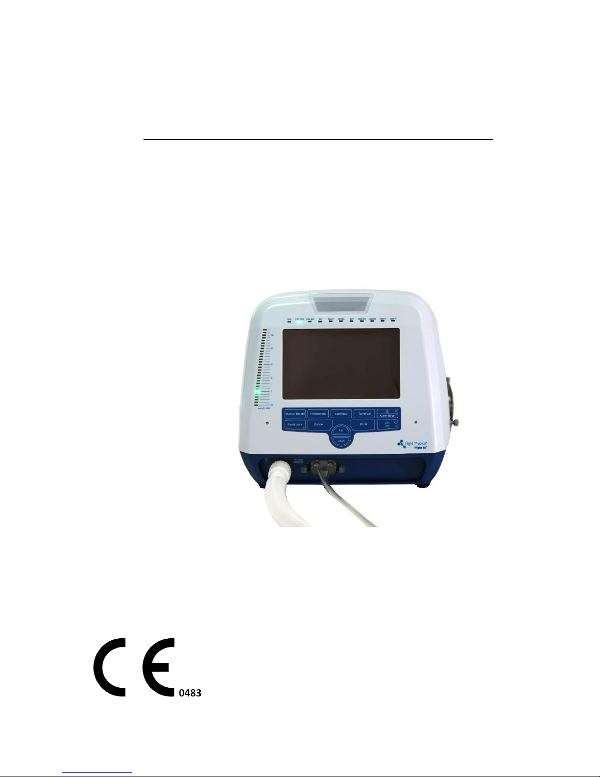
FLIGHT 60 Ventilator
Operator's Manual
V60-00001-18 Rev.D
April 2011

Legal Notice
ii | Flight 60
Legal Notice
Disclaimer
FLIGHT MEDICAL INNOVATIONS LTD. (FLIGHT MEDICAL) provides this Operator’s
Manual in its commitment to help reduce patient risk and injury. However, this
manual is not intended to in any way replace or substitute duty of care to a patient,
professional responsibility, or professional judgment, nor is it intended to provide any
warranty, promise, guarantee, assumption of risk or duty, release, or indemnity.
Physicians shall at all times maintain responsibility for patient treatment and
outcomes, and FLIGHT MEDICAL further assumes no liability for patient treatment or
outcome or for physician's negligence, breach of duty of care, or malpractice.
The FLIGHT 60 Ventilator operator is solely responsible for selecting the appropriate
level and method of patient monitoring.
Product modification or misuse can be dangerous. FLIGHT MEDICAL disclaims all
liability for the consequences of product alterations or modifications, as well as for the
consequences which might result from the combination of this ventilator with other
products, whether supplied by FLIGHT MEDICAL or by other manufacturers, unless
such a combination has been specifically endorsed by FLIGHT MEDICAL.
The design of FLIGHT 60 Ventilator, the Operator’s and Service Manuals, and the
labeling on the ventilator, take into consideration that the purchase and use of the
equipment is restricted to trained professionals, and that certain inherent
characteristics of the ventilator are known to the operator. Instructions, warnings,
and caution statements are therefore limited to the specifics of the FLIGHT 60
Ventilator.
Federal law (US) restricts this device to sale by or on the order of a physician.
This Operator’s Manual excludes references to various hazards which are obvious to
medical professionals and operators of this equipment, to the consequences of
product misuse, and to potential adverse effects in patients with abnormal conditions.
When the FLIGHT 60 Ventilator is used in homecare and subacute environments, only
properly trained personnel should operate the ventilator. The FLIGHT 60 Ventilator is
a restricted medical device designed for use by respiratory therapists or other
properly trained and qualified personnel under the direction of a physician and in
accordance with applicable state laws and regulations.
Transport of patients with the FLIGHT 60 Ventilator requires that medical staff have a
good working knowledge of the ventilator’s use and problem resolution. Proper
emergency backup equipment must be immediately available during transport.

Legal Notice
Operator's Manual | iii
FLIGHT 60 Ventilator operators must recognize their responsibility for implementing
safety monitoring mechanisms which supply appropriate information on equipment
performance and patient condition. Patient safety may be achieved through a wide
variety of means, such as electronic surveillance of equipment performance and
patient condition. However, equipment surveillance should not replace direct
observation of clinical signs.
The liability of FLIGHT MEDICAL is subject to and limited to the exclusive terms and
conditions as set forth herein. Said liability is limited whether arising out of, or related
to, the manufacture and sale of goods, their installation, demonstration, sales
representation, use, performance, or otherwise. Any liability based upon product
warranty is limited regardless of any fault attributable to FLIGHT MEDICAL and the
nature of the action (including breach of warranty, negligence, and strict liability).
The written warranties are in lieu of all other warranties, expressed or implied,
including, without limitation, warranties of merchantability, fitness for any purpose, or
non-infringement.
FLIGHT MEDICAL shall not be liable for any special incidental or consequential
damages incurred by the buyer to a third party. The buyer shall not be entitled to
make liability recoveries from FLIGHT MEDICAL due to such situations.
Warranty
The FLIGHT 60 Ventilator warranty does not apply for/ in case of:
Defects caused by misuse, mishandling, tampering, or by modifications not
authorized by FLIGHT MEDICAL or its representatives.
Rubber and plastic components and materials, which are guaranteed to be free of
defects at time of delivery.
Any product which proves during the warranty period to be defective in workmanship
or material, will be replaced, credited, or repaired. FLIGHT MEDICAL retains the
discretion to select the most suitable of these options. FLIGHT MEDICAL is not
responsible for deterioration, wear, or abuse. In all cases, FLIGHT MEDICAL will not
be liable beyond the original selling price.
Application of this warranty is subject to the following conditions:
FLIGHT MEDICAL or its authorized representatives must be promptly notified upon
detection of the defective material or equipment.
Defective material or equipment must be returned to FLIGHT MEDICAL or its
authorized representative.
Examination by FLIGHT MEDICAL or its authorized representatives must confirm
that the defect is covered by the terms of this warranty.

Legal Notice
iv | Flight 60
The above is the sole warranty provided by FLIGHT MEDICAL. No other warranty,
expressed or implied, is intended. Representatives of FLIGHT MEDICAL are not
authorized to modify the terms of this warranty.
In no way does this or any of FLIGHT MEDICAL's policies, training materials,
guidelines, or instructions create an obligation for FLIGHT MEDICAL to perform any
services.

About this Document
Operator's Manual | v
About this Document
This document contains information intended to ensure safe and effective use of the
FLIGHT 60 Ventilator.
Chapters and Their Contents
1
Introduction
Describes the intended use of the ventilator, symbols
appearing on the ventilator, and an overview of how
the ventilator works.
Pg. 12
2
Safety Instructions
Lists WARNINGS and CAUTIONS to be adhered to, in
order to safely use the ventilator.
Pg. 14
3
Ventilator
Description
Provides a detailed description of the front, back, left,
and right side panels of the ventilator, the ventilator
LCD screens, and the ventilator accessories.
Pg. 19
4
Installation
Describes how to remove the ventilator parts from the
box, mount the ventilator, plug it in, attach the patient
circuit, and install the oxygen accessories.
Pg. 32
5
Using the Ventilator
Describes the basic operation of the ventilator, and
how to set the main, extended, and technical
parameters, initiate ventilation, and monitor the
patient.
Pg. 43
6
Ventilator Alarms
Describes the audible and visual alarms and caution
symbols, alarm specifications, alarm and caution
messages, and how to silence audible alarms, reset
alarms, and set up a remote alarm.
Pg. 72
7
Cleaning and
Maintenance
Describes how to clean and disinfect the ventilator
parts, and how to maintain the ventilator.
Pg. 77
8
Troubleshooting
Describes problems that may arise, their probable
cause, and possible solutions. Also includes contact
information for technical support.
Pg. 85
9
Ventilator Quick
Check Procedure
Describes the testing procedures.
Pg. 95
10
Technical
Specifications
Describes the technical specifications for: hardware,
safety, environmental and oxygen accessories.
Pg. 99
About this Document
vi | Flight 60
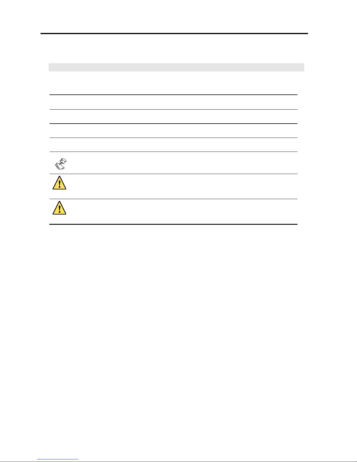
Style Conventions
Convention
Used for
Verdana
Regular text.
Arial Bold
Names of menus, commands, buttons, and other elements of the user interface.
Arial Italics
Special terms, the first time they appear.
Monospace
Text entered by the user.
Notes, which provide additional information intended to avoid inconveniences
during operation. Notes also indicate important procedures to be followed.
CAUTION
Cautions, which indicate possibility of equipment damage, if disregarded.
WARNING
Warnings, which indicate possibility of personal injury to patient or others, if
disregarded.

Table of Contents
Operator's Manual | vii
Table of Contents
LEGAL NOTICE ........................................................................................... II
DISCLAIMER .............................................................................................. II
WARRANTY ............................................................................................... III
ABOUT THIS DOCUMENT ............................................................................. V
TABLE OF CONTENTS ............................................................................... VII
1 INTRODUCTION .................................................................................. 12
1.1 INTENDED USE .................................................................................. 12
1.2 SYMBOLS ......................................................................................... 12
1.3 OVERVIEW ....................................................................................... 13
2 SAFETY INSTRUCTIONS ...................................................................... 14
2.1 GENERAL WARNINGS ........................................................................... 14
2.2 CAUTIONS ........................................................................................ 17
3 VENTILATOR DESCRIPTION ................................................................ 19
3.1 FRONT PANEL FEATURES ....................................................................... 19
3.1.1 LED Indicators ...................................................................... 20
3.2 BACK PANEL FEATURES ......................................................................... 21
3.3 LEFT SIDE PANEL FEATURES ................................................................... 22
3.4 RIGHT SIDE PANEL FEATURES ................................................................. 23
3.5 LCD SCREENS ................................................................................... 23
3.5.1 Alarm and Power Management Area ........................................ 23
3.5.2 Patient Monitoring Area ......................................................... 24
3.5.3 Control Area ......................................................................... 25
Parameters Screen ........................................................................................................ 25
Extended Screen ........................................................................................................... 27
Technical Screen ........................................................................................................... 28
3.6 ACCESSORIES .................................................................................... 30
3.6.1 Air/Oxygen Entrainment Mixer ................................................ 30
3.6.2 Oxygen Blending Bag Kit ........................................................ 30

Table of Contents
viii | Flight 60
4 INSTALLATION ................................................................................... 32
4.1 INTRODUCTION .................................................................................. 32
4.2 REMOVING THE VENTILATOR PARTS FROM THE BOX ........................................ 32
4.3 MOUNTING THE VENTILATOR .................................................................. 32
4.4 INSTALLING THE DETACHABLE BATTERY ..................................................... 33
4.5 PLUGGING IN THE POWER CORD (FOR AC) .................................................. 33
4.6 ATTACHING THE PATIENT CIRCUIT ............................................................ 34
4.7 INSTALLING OXYGEN ACCESSORIES .......................................................... 35
4.7.1 The Air/Oxygen Entrainment Mixer .......................................... 36
Installing the Air/Oxygen Entrainment Mixer ..................................................................... 37
4.7.2 The Oxygen Blending Bag Kit ................................................. 38
Installing the Oxygen Blending Bag Kit ............................................................................. 39
Disassembling and Cleaning the Oxygen Blending Bag Kit .................................................. 40
Monitoring the Oxygen Supply Flow in the Oxygen Blending Bag ......................................... 40
5 USING THE VENTILATOR .................................................................... 43
5.1 BASIC OPERATION .............................................................................. 43
5.1.1 Powering On the Ventilator ..................................................... 43
5.1.2 Turning Off the Ventilator ...................................................... 44
5.1.3 Navigating Between Screens .................................................. 44
5.1.4 Setting Control Values ........................................................... 44
Default and Saved Values ............................................................................................... 45
5.1.5 Delivering a Manual Breath .................................................... 45
5.1.6 Locking the Panel .................................................................. 45
5.1.7 Canceling Parameter Adjustments ........................................... 46
5.1.8 Accepting Parameter Adjustments ........................................... 46
5.1.9 Changing Parameter Value (Up/Down Button) .......................... 46
5.2 SETTING THE MAIN PARAMETERS ............................................................. 46
5.2.1 Mode of Operation ................................................................ 46
ACMV Mode ................................................................................................................. 46
SIMV Mode (Synchronized Intermittent Mandatory Ventilation) ........................................... 47
SPONT Mode (Spontaneous Ventilation) ........................................................................... 48
5.2.2 Submode of Operation (VCV/PCV) ........................................... 48
Volume Control Ventilation (VCV) .................................................................................... 49

Table of Contents
Operator's Manual | ix
Pressure Control Ventilation (PCV) ................................................................................... 51
5.2.3 Inspiratory Time (Ti) / Flow .................................................... 52
Inspiratory Time ............................................................................................................ 53
Flow Rate .................................................................................................................. 53
5.2.4 Frequency of Breaths (f) ........................................................ 54
5.2.5 Pressure Trigger Level (Ptrig) ................................................. 54
5.2.6 Positive End Expiratory Pressure (PEEP) ................................... 55
5.2.7 Pressure Support Ventilation (PSV) ......................................... 55
5.2.8 Lower and Upper Pressure Limits (Low P, High P) ...................... 56
5.2.9 Lower and Upper Minute Volume Alarm Limits (Low MV, High MV)57
Low MV .................................................................................................................. 57
High MV .................................................................................................................. 58
5.2.10 Settings Limitation Pop-Up Messages ....................................... 58
5.3 SETTING THE EXTENDED PARAMETERS ....................................................... 59
5.3.1 Alarm Buzzer Volume ............................................................ 59
5.3.2 Activating/Deactivating Power Saving ...................................... 59
5.3.3 Waveform Type .................................................................... 60
5.3.4 Inspiratory Time / Flow Control (TI / Flow ctl.) ......................... 61
5.3.5 Rise Profile ........................................................................... 61
5.3.6 Pressure Support Flow Termination (PSV Flow Term) ................. 62
5.3.7 Pressure Support Ventilation Inspiratory Time (PSV Ti) .............. 63
5.3.8 Activating/Deactivating the O2 Enrichment Monitor (FiO2) ......... 63
High and Low Levels for the Oxygen Alarm (FiO2 Low and FiO2 High) .................................. 64
5.3.9 Apnea .................................................................................. 64
Backup Ventilation in ACMV and SIMV Modes .................................................................... 65
Backup Ventilation in SPONT Mode .................................................................................. 65
Cancellation of Backup Ventilation ................................................................................... 65
5.4 SETTING THE TECHNICAL PARAMETERS ...................................................... 66
5.4.1 System Language ................................................................. 66
5.4.2 Pressure Units Display (Press Units) ........................................ 66
5.4.3 Activating/Deactivating the SPONT Mode Low Pressure Alarm (LOW P
Spont) .......................................................................................... 66
5.4.4 Displaying the System Information .......................................... 67
5.4.5 Performing Exhalation Valve Calibration ................................... 67
5.4.6 Storing/Loading a Ventilation Configuration .............................. 68

Table of Contents
x | Flight 60
5.4.7 System Clock ....................................................................... 69
5.4.8 Displaying the Alarms/Changes Log ......................................... 69
5.4.9 Accessing the Advanced Technical Menu .................................. 70
5.5 INITIATING VENTILATION ...................................................................... 70
5.6 MONITORING THE PATIENT .................................................................... 71
6 VENTILATOR ALARMS ......................................................................... 72
6.1 AUDIBLE ALARM AND CAUTION SIGNALS .................................................... 72
6.2 VISUAL ALARM AND CAUTION SIGNALS ...................................................... 72
6.3 ALARM AND CAUTION SPECIFICATIONS ...................................................... 73
6.3.1 Variable Ventilation Alarms .................................................... 73
6.3.2 Automatic Ventilation Alarms .................................................. 74
6.3.3 Automatic Technical Alarms .................................................... 74
6.3.4 Cautions .............................................................................. 75
6.4 SILENCING AUDIBLE ALARMS .................................................................. 75
6.5 RESETTING ALARMS ............................................................................ 76
6.6 SETTING UP A REMOTE ALARM ................................................................ 76
7 CLEANING AND MAINTENANCE ........................................................... 77
7.1 CLEANING AND DISINFECTING ................................................................ 77
7.1.1 FLIGHT 60 Ventilator ............................................................. 77
7.1.2 FLIGHT 60 Ventilator Accessories ............................................ 77
Oxygen Blending Bag Kit ................................................................................................ 78
Reusable (Single Patient) Patient Circuits ......................................................................... 78
Reusable (Single Patient) Exhalation Valve ....................................................................... 80
FLIGHT 60 Ventilator Air Inlet Particle Filter ...................................................................... 82
7.2 MAINTENANCE ................................................................................... 82
7.2.1 Preventive Maintenance ......................................................... 82
7.2.2 Internal Battery Maintenance ................................................. 83
7.2.3 15,000 Hour Maintenance ...................................................... 83
7.3 GENERAL WARNINGS ........................................................................... 84
8 TROUBLESHOOTING ........................................................................... 85
8.1 INTRODUCTION .................................................................................. 85
8.2 ALARMS .......................................................................................... 85

Table of Contents
Operator's Manual | xi
8.3 GENERAL/CLINICAL ............................................................................. 88
8.4 AIR/OXYGEN ENTRAINMENT MIXTURE ........................................................ 93
8.5 CONTACT INFORMATION ........................................................................ 94
9 VENTILATOR QUICK CHECK PROCEDURE ............................................ 95
9.1 INTRODUCTION .................................................................................. 95
9.1.1 Setting Up the Ventilator for the Test ...................................... 95
9.2 QUICK CHECK PROCEDURE .................................................................... 96
9.2.1 Checking the Power Management ............................................ 96
9.2.2 Checking the Alarms ............................................................. 97
9.2.3 Checking the Monitored Parameters ........................................ 97
9.3 CHECK-OFF SHEET.............................................................................. 98
10 TECHNICAL SPECIFICATIONS ............................................................. 99
10.1 PHYSICAL SPECIFICATIONS .................................................................... 99
10.2 PNEUMATIC SPECIFICATIONS .................................................................. 99
10.3 ELECTRICAL SPECIFICATIONS .................................................................. 99
10.4 INTERNAL BATTERY SPECIFICATIONS ....................................................... 100
10.5 SAFETY AND PARTICULAR STANDARD SPECIFICATIONS .................................. 100
10.6 ENVIRONMENTAL SPECIFICATIONS .......................................................... 101
10.7 AIR/OXYGEN ENTRAINMENT MIXER SPECIFICATIONS .................................... 101
10.8 OXYGEN BLENDING BAG KIT SPECIFICATIONS ............................................ 101
Introduction
Intended Use
12 | Flight 60
1 Introduction
This Operator’s Manual (V60-00001-18) contains information intended to ensure safe
and effective use of the FLIGHT 60 Ventilator.
1.1 Intended Use
The FLIGHT 60 Ventilator is intended to provide continuous or intermittent
mechanical ventilation support for the care of individuals who require mechanical
ventilation. Specifically, the FLIGHT 60 is applicable for adult and pediatric (i.e.,
infant, child and adolescent) patients, greater than or equal to 10kg (22 lbs).
The FLIGHT 60 Ventilator is a restricted medical device intended for use by qualified,
trained personnel under the direction of a physician; it is suitable for use in hospital,
sub-acute, emergency room, and home care environments, as well as for transport
and emergency response applications
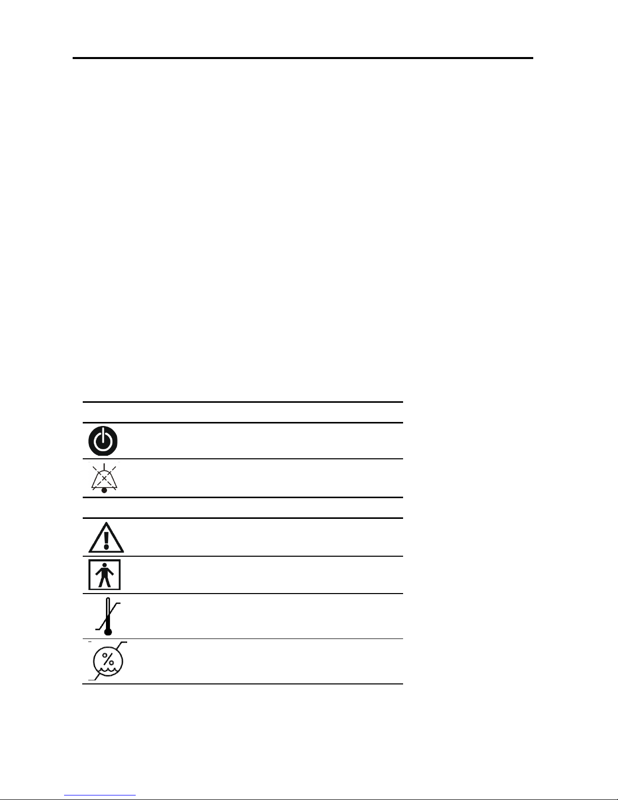
1.2 Symbols
Symbol
Description
Front Panel
On/Off button
Audio Paused
Rear Panel
Caution; consult accompanying documents
Type BF applied part
Temperature limitation
Humidity limitation
Introduction
Overview
Operator's Manual | 13
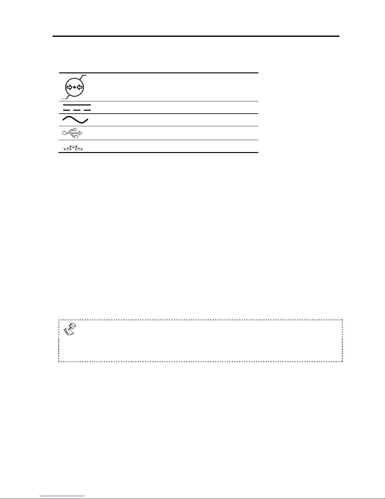
Symbol
Description
Atmospheric pressure limitation
DC – Direct Current
AC – Alternating Current
USB – Universal Serial Bus
LAN – Local Area Network
1.3 Overview
The FLIGHT 60 Ventilator is an electrically powered, microprocessor controlled
ventilator with pressure support for spontaneous breathing. It can be pressure or
time activated, volume or pressure limited, and time, pressure, or flow cycled.
Backup ventilation is available, manual inflation is possible, and there is an
emergency intake valve which allows the patient to pull ambient air into the patient
circuit in the event of a complete loss of supply of gas pressure. Opening pressure is
approximately –3 cmH2O (–3 mbar) during emergency intake.
The FLIGHT 60 Ventilator may be powered by external power (100-240 VAC or 12-15
VDC) or by its Li Ion internal batteries. Two internal Li Ion rechargeable batteries
power the ventilator for up to 12 hours when fully charged.
The main component of the pneumatic system is an electrically controlled pump. This
pump provides a compressed gas source so that no external air compressor is
needed. Additionally, the exhalation valve is activated by an electrically controlled
proportional solenoid.
Transport of patients with the FLIGHT 60 Ventilator requires that medical staff
have a good working knowledge of the ventilator’s use and problem resolution.
Proper emergency backup equipment must be immediately available during
transport.
Safety Instructions
General Warnings
14 | Flight 60
2 Safety Instructions
At all times, strictly follow this manual. The safe use of the FLIGHT 60 Ventilator
requires full understanding of its operation, and adherence to the manual's
instructions. The equipment is only to be used for the purpose specified in Section
1.1. Observe all of the WARNINGS and CAUTIONS posted in this manual, and on
buttons found on the FLIGHT 60 Ventilator and associated accessories.
2.1 General Warnings
External power connection: To maintain grounding integrity when using AC
power, only connect to hospital grade receptacles. Always disconnect the
external power supply prior to servicing. There is a risk of explosion if used in
the presence of flammable anesthetics.
All settings and adjustments in the different ventilation modes must be made
in accordance with a physician's prescribed therapy.
Do not use electrically conductive patient circuits.
Always use a clean, disinfected patient circuit.
Always use an outlet filter or equivalent at the Airway Pressure Connector, to
protect the internal transducers from moisture and other contaminants.
Always use appropriate monitors to ensure sufficient oxygenation and
ventilation (such as pulse oximeter and/or capnograph) when the FLIGHT 60
Ventilator is in use on a patient.
Safety Instructions
General Warnings
Operator's Manual | 15
The ventilator is ready for operation only when:
It is completely assembled.
The Quick Check Procedure, including the Exhalation Valve Calibration has
been successfully completed.
Constant attention by qualified medical personnel is recommended whenever a
patient is ventilated with the FLIGHT 60 Ventilator.
If a fault is detected in the ventilator and its life support functions are in doubt,
immediately discontinue use; use an alternative method of ventilation until the
fault has been corrected, and contact your provider or FLIGHT MEDICAL
immediately.
Failure to identify and correct alarm violations may result in patient injury.
Ensure that the oxygen source is not empty before and during the use of the
optional Air/Oxygen Entrainment Mixer or Oxygen Blending Bag Kit.
As Li-Ion batteries are charged and discharged over time, their ability to hold a
charge is decreased with use. This can shorten the length of time the ventilator
can function while on battery power.
The batteries should be replaced when the batteries no longer meet the needs
of the user. This depends on a number of factors including settings and usage
patterns.
When the FLIGHT 60 Ventilator is used for transport applications, ensure that
the internal batteries are fully charged prior to use.
Safety Instructions
General Warnings
16 | Flight 60
When the Battery Empty alarm sounds, only a limited amount of battery power
remains, and an alternate power source should be found immediately.
Charge the batteries for a minimum of three hours before powering the
ventilator from the batteries. This provides fully charged batteries.
During storage, charge the batteries for a minimum of three hours every 30
days. This provides charged batteries.
Always ensure that the green Ext. Power LED is illuminated after connecting
the FLIGHT 60 Ventilator to an external AC or DC power source. If the LED is
not illuminated, check all power connections and resolve any problems.
Always plug the FLIGHT 60 Ventilator into an AC power supply source when not
in use, to ensure best battery performance.
The flow resistance of the air inlet filter, located on the right side of the
ventilator, is likely to increase with repeated use. Ensure that the filter is
changed regularly.
Only a FLIGHT MEDICAL approved patient circuit can be used with the FLIGHT
60 Ventilator.
Only a FLIGHT MEDICAL approved exhalation valve can be used with the
FLIGHT 60 Ventilator.

Safety Instructions
Cautions
Operator's Manual | 17
Perform an exhalation valve calibration each time a circuit/exhalation valve is
installed.
This FLIGHT 60 Ventilator has been tested and found to comply with EMC limits
according to EN60601-1-1-2 standard class B. These limits are designed to
provide reasonable protection against harmful interference in a typical medical
installation. The equipment generates uses and can radiate radio frequency
energy and, if not installed and used in accordance with these instructions,
may cause harmful interference to other devices in the vicinity. There is no
guarantee that interference will not occur in a particular installation. If this
equipment does cause harmful interference with other devices, which can be
determined by turning the equipment off and on, the user is encouraged to try
to correct the interference by one or more of the following measures:
Reorient or relocate the receiving device.
Increase the distance between the equipment.
Connect the equipment into an outlet on a circuit different from that to which
the device (s) is connected.
Consult the manufacturer for help.
2.2 Cautions
Only use medical grade oxygen with the Air/Oxygen Entrainment Mixer or
Oxygen Blending Bag Kit.
Do not place liquid containers in the immediate vicinity or on top of the FLIGHT
60 Ventilator. Liquids that get into the ventilator can cause equipment
malfunction and damage.
An authorized FLIGHT MEDICAL factory-trained technician must do all service
or repairs performed on the FLIGHT 60 Ventilator.
Do not open the ventilator or perform service on an open unit while connected
to external power.
Safety Instructions
Cautions
18 | Flight 60
Use standard antistatic techniques while working inside the ventilator or
handling any electronic parts.
Clean all external parts of the ventilator prior to servicing.
Water in the oxygen supply can cause equipment malfunction and damage.
Batteries contain Li-Ion. Do not discard them in an incinerator or force them
open. Batteries should not be disposed of with normal waste.
Review FLIGHT 60 Ventilator Operator’s Manual before servicing the ventilator.
Use the tools and equipment specified in this manual to perform specific
procedures.
Ventilator Description
Front Panel Features
Operator's Manual | 19
3 Ventilator Description
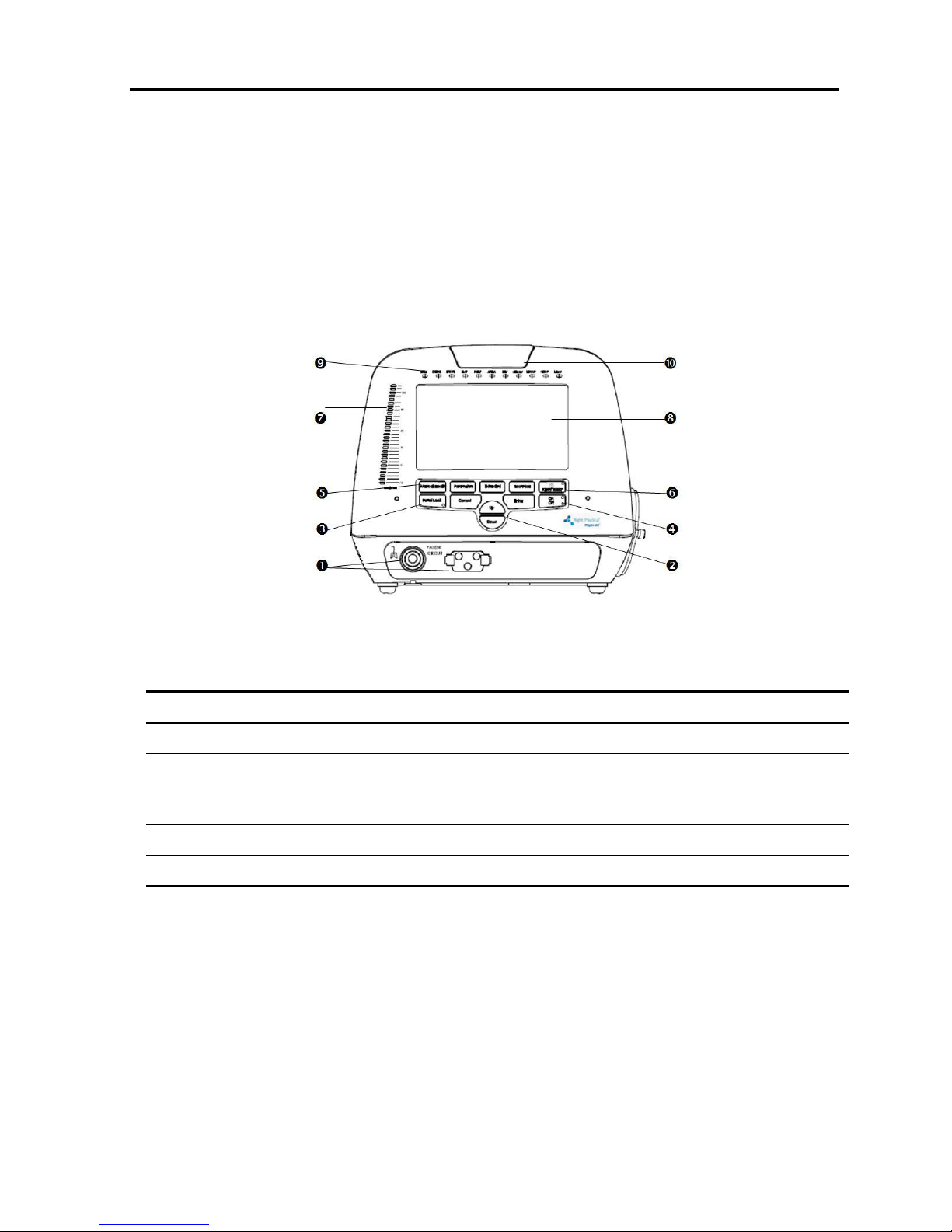
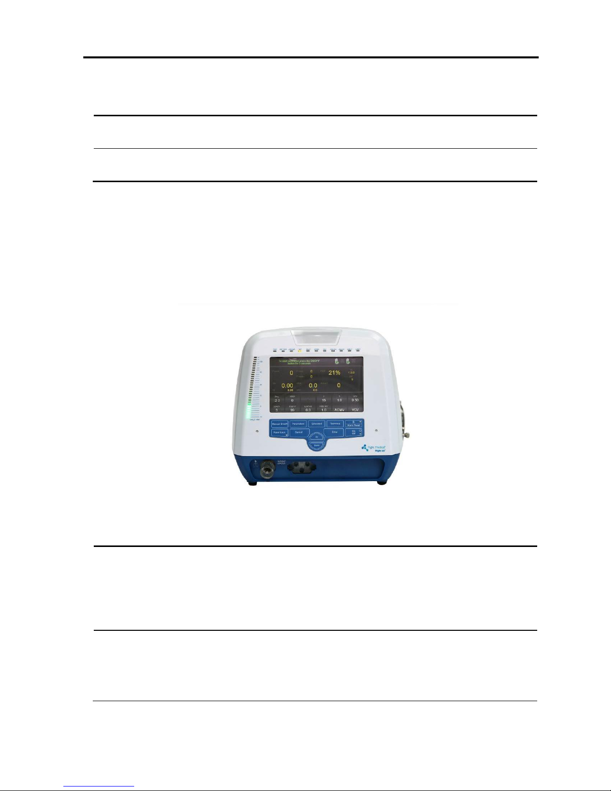
3.1 Front Panel Features
The front panel contains the control buttons, visual indicators, display screen, and
patient circuit connection.
Figure 1 – Front Panel
Label
Name
Description
1
Patient Circuit Connector
Composed of a gas outlet and quick connector.
2
Up/Down button
Enables the user to scroll up and down the display controls.
3
Panel Lock button
Enables the user to lock the ventilator’s control, preventing
accidental changes. Pressing the button of a locked panel and
then Enter, unlocks the panel.
4
On/Off button
Turns the ventilator on or off, to start or stop ventilation.
5
Manual Breath button
Delivers a user initiated manual inflation.
6
Audio Paused / Alarm Reset
button
Toggle button. Pressing Audio Paused temporarily silences the
audible alarm; pressing Alarm Reset clears latched alarm LEDs.
7
Pressure Gauge
The pressure gauge is a visual indicator of breath activity, which
shows the dynamic movements of the breath pressures. When a
breath is being delivered, the user can see the relative pressure
and phase of the breath (inspiration or expiration).
The pressure gauge is comprised of 29 LEDs. From -10 to +20
cmH2O, each notch equals 2 cmH2O; from 20 to 50 cmH2O, each
notch equals 5 cmH2O; above 50 cmH2O, each notch equals 10
cmH2O.

Ventilator Description
Front Panel Features
20 | Flight 60
Label
Name
Description
8
Display touch screen
Enables the user to modify the ventilation, alarm, and technical
settings, and to view real time patient data, alarms, and logs.
9
LED Indicators
Inform the user of various events (see Section 3.1.1).
10
Primary Alarm LED
Flashes red to indicate that there is a high priority alarm.
3.1.1 LED Indicators
The LED indicators on the front panel inform the user of various events.
The following table describes the available LED indicators.
LED Indicator
Description
TRIG
Green LED indicates a patient’s breathing effort.
EXT PWR
Green LED indicates that an external power source is being applied to the ventilator.
LOW BAT
Red LED indicates that detachable battery charge level has drop below 20%..
BAT
Orange LED indicates that the ventilator is powered on batteries.
FAULT
Red LED indicates a ventilator malfunction.
APNEA
Red LED indicates that the apnea alarm limit is being violated`
BUV
Red LED indicates that backup ventilation is active.
HIGH MV
Red LED indicates that the high minute volume alarm limit is being violated.
LOW MV
Red LED indicates that the low minute volume alarm limit is being violated.
HIGH P
Red LED indicates that the high peak airway pressure alarm limit is being violated.
LOW P
Red LED indicates that the low airway pressure alarm limit is being violated.
Ventilator Description
Back Panel Features
Operator's Manual | 21
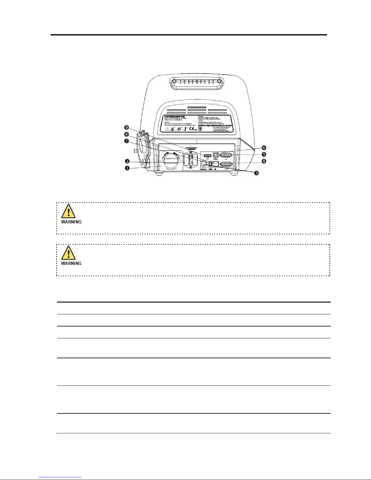
3.2 Back Panel Features
Figure 2 – Back Panel
To ensure proper grounding and prevent possible shock hazards, this device
should only be connected to grounded power receptacles.
HOME CAREGIVERS: External power in the home environment must support
min. 100 to max. 240 V AC, and must have a grounded receptacle.
Label
Name
Description
1
Detachable Battery
2
AC Connector with Fuses
100 – 240 V AC, 50 – 60 Hz, Fuses 2x8A (time lag)
3
DC Connector
12 – 15 V DC
4
RS-232 Serial Port (COM2)
Remote alarm connector (Normally Open and Normally Closed
options).
5
RS-232 Serial Port (COM1)
Online output of events and error messages to the PC, using a
dedicated PCS2 protocol; for authorized and qualified service
technicians only.
6
USB B type
PC connector: USB port for downloading the main application from
the PC using a dedicated PCS2 protocol; for authorized and
qualified service technicians only.
7
USB A type
USB port for uploading LOG files to an external memory stick; for
authorized and qualified service technicians only.
Ventilator Description
Left Side Panel Features
22 | Flight 60
Label
Name
Description
8
LAN (RJ45)
LAN for network logging (currently not available).
9
Mini RS-485 (COM3)
For connecting FLIGHT MEDICAL peripherals. For future use.
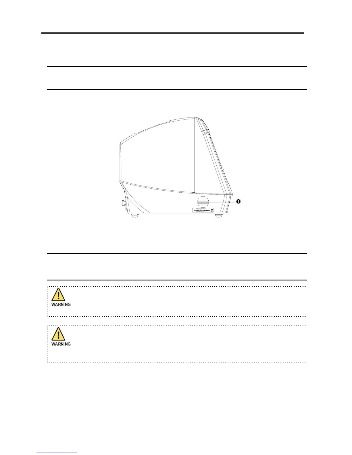
3.3 Left Side Panel Features
Figure 3 – Left Side Panel
Label
Name
Description
1
Emergency Air Intake
Enables the patient to pull ambient air into the patient circuit in the
event of a complete system failure. The Air Intake opening pressure
is approximately -3 cmH2O (-3 mbar).
Do not obstruct the Emergency Air Intake! Any impediment can result in
patient suffocation.
HOME CAREGIVERS: Should a complete failure of the ventilator occur, the
Emergency Air Intake allows the patient to breathe from room air through the
intake valve. Blockage of the valve can result in suffocation.
Ventilator Description
Right Side Panel Features
Operator's Manual | 23
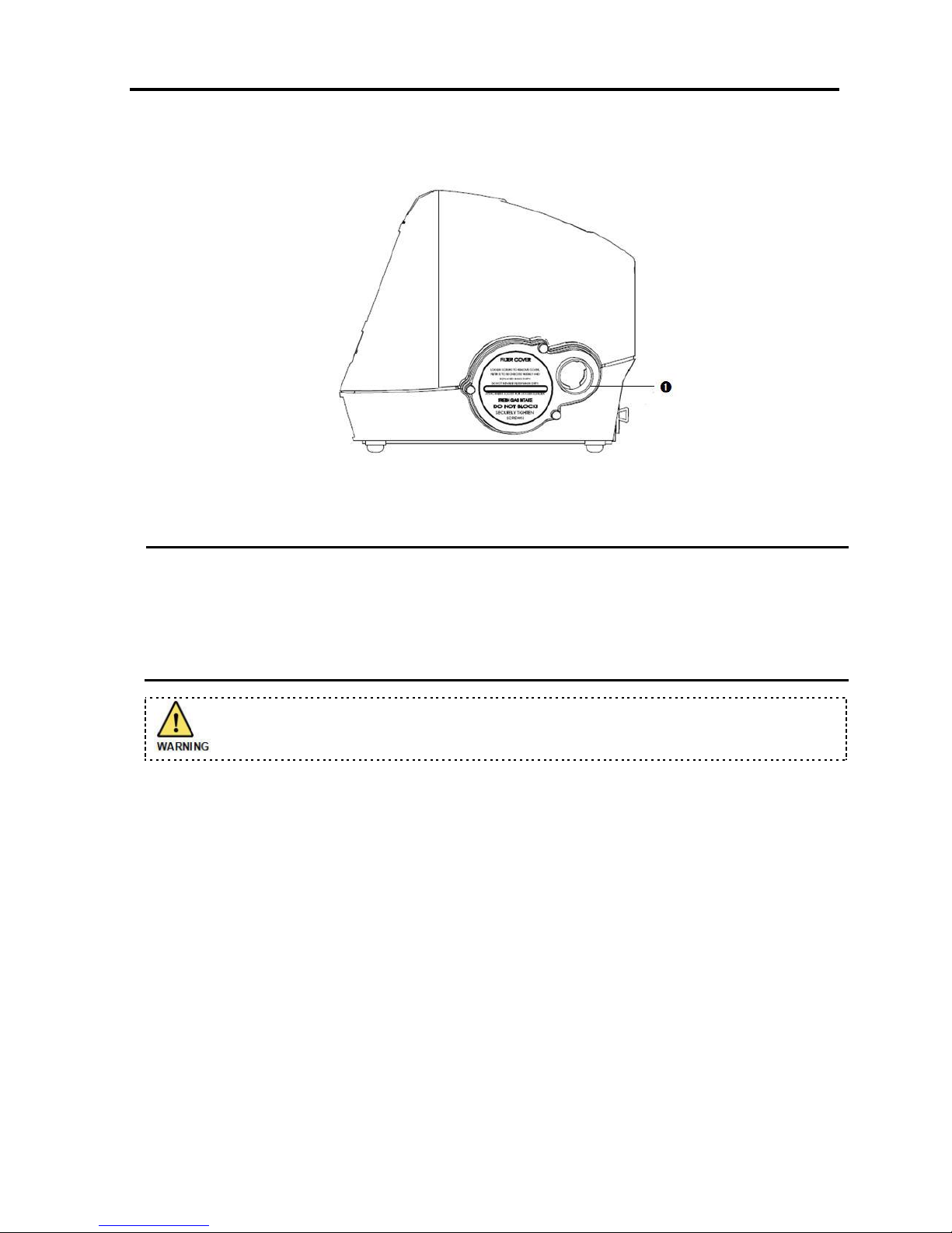
3.4 Right Side Panel Features
Figure 4 - Right Side Panel
Label
Name
Description
1
Fresh Gas Intake and
Filter Cover
Environmental air enters through this 30 mm ID Fresh Gas Intake.
The air inlet particle filter is placed behind the Filter Cover to protect
the patient as well as the ventilator’s piston system from dirt and
particles. The Fresh Gas Intake also serves as the attachment socket
for the optional FLIGHT 60 Ventilator Air/Oxygen Entrainment Mixer
or Oxygen Blending Bag.
Do not block the Fresh Gas Intake.
3.5 LCD Screens
The LCD screen of the FLIGHT 60 Ventilator is divided into three sections:
Alarm and power management area – the top section of the screen (see Section
3.5.1).
Patient monitoring area – the middle section of the screen (see Section 3.5.2).
Control area – the bottom part of the screen; it can display the main parameters,
extended parameters, or technical parameters (see Section 3.5.3).
3.5.1 Alarm and Power Management Area
The Alarm and Power Management area displays the following:

Ventilator Description
LCD Screens
24 | Flight 60
Alarms and Cautions – Left side of this area. Up to three alarms (alarm
messages) and/or cautions are displayed, according to their priority.
Battery icons – Right side of this area. Battery icons show:
Battery capacity (%)
Color – Green battery icon indicates that there is sufficient capacity; orange
indicates low capacity.
Arrows – Up arrows on the battery icon indicate that batteries are charging;
down arrows indicate that the batteries are depleted.
3.5.2 Patient Monitoring Area
Patient monitoring parameters are displayed at all times on the Parameters,
Extended, and Technical screens, to ensure continuous monitoring of the patient
during ventilation.
The following table describes the patient monitoring parameters.
Name
Description
Range
Resolution
Updated
P Peak
Peak Inspiratory Pressure
0 to 99 cmH2O
1 cmH2O
Breath by breath
P base
Baseline airway pressure
at the end of expiration
0 to 99 cmH2O
1 cmH2O
Breath by breath
P mean
Mean airway pressure
0 to 99 cmH2O
1 cmH2O
10 seconds rolling average
Vte
Expiratory Tidal Volume
0 to 9.99 L
10 ml
Breath by breath
Vti
Inspiratory Tidal Volume
0 to 9.99 L
10 ml
Breath by breath
MVe
Expiratory Minute Volume
0 to 99.9 L/min
1 L/min
10 seconds rolling average
MVi
Inspiratory Minute
Volume
0 to 99.9 L/min
1 L/min
10 seconds rolling average
Actual f
Total number of patient
or time activated breaths
99 b/min
1 b/min
Breath by breath
I:E
I:E Ratio
1:99 to 3:1
Note: I:E Ratio is determined by the ƒ and Ti settings. If the expiratory time is longer than the
inspiratory time, the display format is 1:X.X. If the expiratory time is shorter than Ti, the
display format is X.X:1.
Ventilator Description
LCD Screens
Operator's Manual | 25
Name
Description
Range
Resolution
Updated
PIF
Peak Inspiratory Flow
6 to 100 L/min
1 L/min
Breath by breath
FiO2
Fraction of Inspired
Oxygen
21% to 100% O2
1%
Every 10 seconds
3.5.3 Control Area
Parameters Screen
Pressing the Parameters button switches over to the main settings screen. This is the
default screen in standby and ventilation mode. The display always switches back
automatically to Parameters from the Extended or Technical settings display.
Figure 5 – Parameters Settings
Button
Description
Ptrig
Used to determine the pressure trigger level (trigger sensitivity) in terms of how far the
airway pressure must drop below the set baseline pressure in order for a patient's
spontaneous efforts to be detected.
Range: -0.1 to -9.9 cmH2O/mbar
Resolution: 0.1 cmH2O/mbar
PEEP
Used to establish a baseline positive airway pressure in the patient circuit during the
exhalation phase.
Range: 0, 3 to 30 cmH2O/mbar
Resolution: 1 cmH2O/mbar

Ventilator Description
LCD Screens
26 | Flight 60
Button
Description
PSV
Used to determine the level of support in pressure during inspiration, for patient triggered
spontaneous breaths.
Range: 0 to 60 cmH2O/mbar
Resolution: 1 cmH2O/mbar
f
Used to set the frequency of breaths. In ACMV mode, it determines the number of timetriggered breaths; in SIMV mode, it determines the total number of mandatory breaths.
Range: 1 to 99 b/min
Resolution: 1 b/min
FLOW
Used to set the mandatory flow (volume control).
This control button appears only if FLOW is selected in the Ti/FLOW control button on the
extended parameters screen. Otherwise, the Ti button appears (see button below).
Range: 6 to 100 L/min
Resolution: 1 L/min
Ti
Used to set the inspiratory time for mandatory breaths (volume or pressure control).
This control button appears only if Ti is selected in the Ti/FLOW control button on the
extended parameters screen. Otherwise, the FLOW button appears (see above button).
Range: 0.1 to 3.0 seconds
Resolution: 0.1 seconds
VCV
Used to set the mandatory tidal volume for the VCV submode.
Range: 0.1 to 2.2 L
Resolution: 0.01 L
PCV
Used to set the target pressure for the PCV submode.
Range: 5 to 60 cmH2O/mbar
Resolution: 1 cmH2O/mbar
LOW P
Used to set the minimum allowed pressure of a mandatory breath.
Range: 3 to 98 cmH2O/mbar
Resolution: 1 cmH2O/mbar
HIGH P
Used to set the maximum allowed pressure value of a mandatory breath.
Range: 4 to 99 cmH2O/mbar
Resolution: 1 cmH2O/mbar
Ventilator Description
LCD Screens
Operator's Manual | 27
Button
Description
LOW MV
Used to set the minimum Minute Volume allowed for a patient.
Range: 0.0 to High MV – 1
Resolution: 0.1 L
HIGH MV
Used to set the maximum Minute Volume allowed for a patient.
Range: Low MV + 1.0 to 50
Resolution: 0.1 L
MODE
Used to select the ventilator mode.
Available options: ACMV (Assist/Control Mandatory Ventilation)
SIMV (Synchronized Intermittent Mandatory Ventilation)
SPONT (Spontaneous Ventilation)
PCV/VCV
Used to select the ventilator submode.
Available options: PCV (pressure control ventilation)
VCV (volume control ventilation)
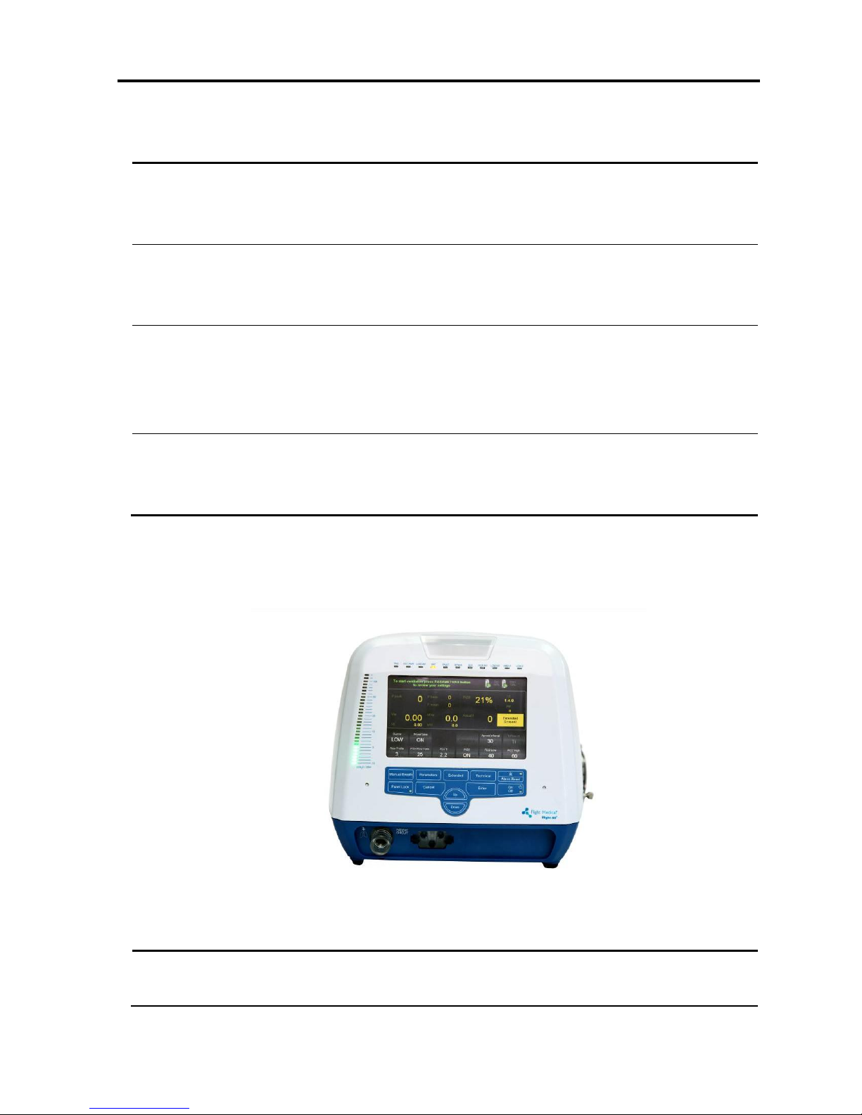
Extended Screen
Pressing the Extended button switches over to the extended settings screen.
Figure 6 – Extended Settings
Button
Description
Buzzer
Used to set the alarm buzzer volume.
Available options: HIGH and LOW

Ventilator Description
LCD Screens
28 | Flight 60
Button
Description
PowerSave
Used to activate/deactivate the power saving system in the AC and DC supply. When
activated, the screen turns Off and the pressure gauge displays one LED only to indicate
the peak pressure.
Waveform
Used to select the type of waveform:
Square - the flow stays constant during the inspiratory phase
Descend - the flow descends linearly until the final flow (at the end of inspiration) and is
50% of the peak flow. (Peak flow is calculated based on the tidal volume and inspiratory
time.)
This option is enabled only in VCV mode.
Apnea
Interval
Used to set the maximum allowed time of apnea.
Ti/Flow ctl.
Used to specify whether the Inspiratory Time or the Flow criteria will stay constant
during Volume Controlled management.
Rise Profile
Used to set the rise level that the system will deliver. Available levels are 1 (the fastest)
to 5 (the slowest).
This option is enabled only in PCV and PSV modes.
PSV Flow
Term
Used to set the expiratory trigger from 10% to 70% of the peak flow.
This option is enabled only in PSV mode.
PSV Ti
Used to control and limit the inspiratory time in Pressure Support Ventilation from 0.1 to
3 seconds.
FiO2
Used to activate or deactivate O2 enrichment monitoring. Activating FiO2 displays the
FiO2 value on the screen; deactivating it turns the display off.
FiO2 Low
Used to define the low value of oxygen in the ventilator air mixture that sets off the
alarm. The low value can be set to any value between OFF (min value 21%) and FiO2
High minus 10.
Enabled only when FiO2 is activated (ON).
FiO2 High
Used to define the high value of oxygen in the ventilator air mixture that sets off the
alarm. The high value can be set to any value between FiO2 Low plus 10 to OFF (max
value 100%).
Enabled only when FiO2 is activated (ON).
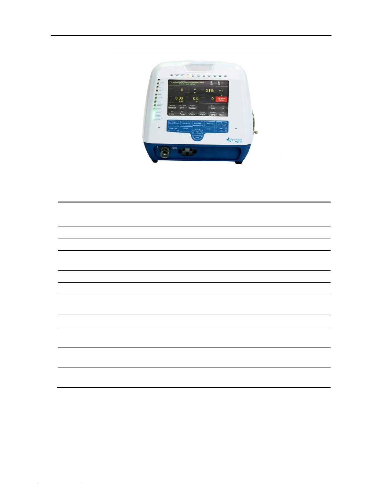
Technical Screen
Pressing the Technical button switches over to the technical settings screen.
Ventilator Description
LCD Screens
Operator's Manual | 29
Figure 7 – Technical Settings
Button
Description
Press Units
Used to determine in which units the pressure is displayed on the ventilator.
Available options: cmH2O and mbar
LOW P Spont
Used to activate/deactivate the low-pressure alarm in SPONT mode.
Language
Used to select the display language of the ventilator.
Show Info
Used to display the following system information: Unit Serial Number, Software Version,
Compressor Serial Number, Hour Meter, and Next Service.
Valve CAL
Used to enter the patient circuit exhalation valve calibration process.
Set Load
Used to load a ventilation configuration that has been predefined in the ventilator.
Set Save
Used to save a ventilation configuration in the ventilator, for later use; up to five
configurations can be saved.
Set Clock
Used to set the system time and date, for logging purposes.
Show Log
Alarm
Used to display the alarms that have occurred, by date, time, and type.
Show Log
Change
Used to display the changes that have been made to the ventilator states, modes, and
settings. These changes are displayed by date, time, type, and values.
Goto More…
Used to access the advanced technical menu. This function is available to authorized and
qualified service technicians. Please refer to the Service Manual.
Ventilator Description
Accessories
30 | Flight 60
3.6 Accessories
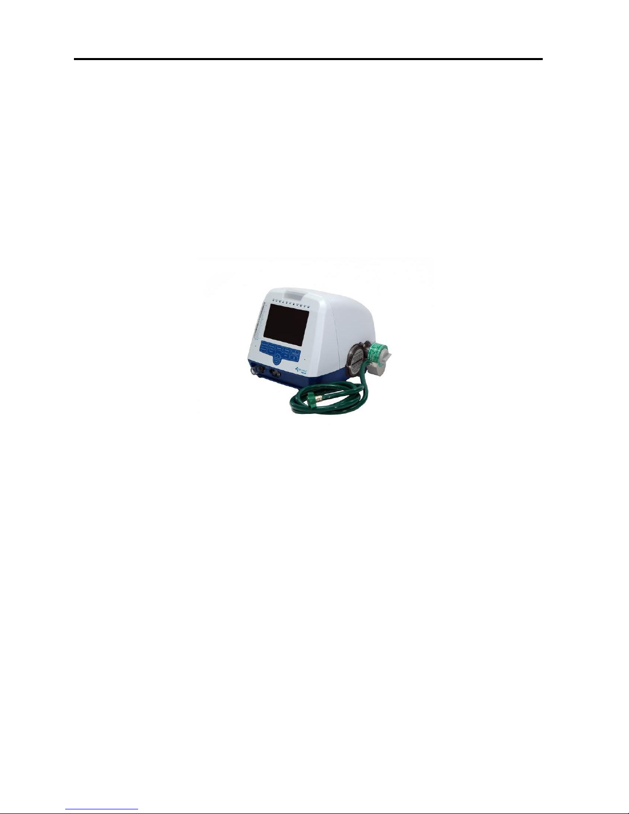
3.6.1 Air/Oxygen Entrainment Mixer
The Air/Oxygen Entrainment Mixer is used to blend atmospheric air with medical
grade oxygen at a precise ratio. A control knob allows for incremental adjustment
from 21% to 100% FIO2. The high pressure oxygen hose has a standard female
DISS 1240 connection. The Mixer attaches to the Fresh Gas Intake of the FLIGHT 60
Ventilator on the Filter Cover, located on the right side of the ventilator.
Pneumatic Requirements: Oxygen 35-90 psig (2.4 to 6.2 Bar)
Figure 8 - High Pressure Oxygen Mixer
3.6.2 Oxygen Blending Bag Kit
The Oxygen Blending Bag Kit is used to blend atmospheric air with a low flow (0 to
10 L/min) medical grade oxygen source. The Oxygen Blending Bag Kit attaches to
the Fresh Gas Intake on the Filter Cover, located on the right side of the ventilator.
This system allows the user to ventilate patients with oxygen enriched gas from 21%
to 100% FiO2.
Pneumatic Requirements: Oxygen 0-10 L/min
 Loading...