

Flight Medical Innovations 60 Series, 60 SL, 60 DL, 60 iO2, FLIGHT 60T Series Service Manual
...
FLIGHT MEDICAL INNOVATIONS Ltd.
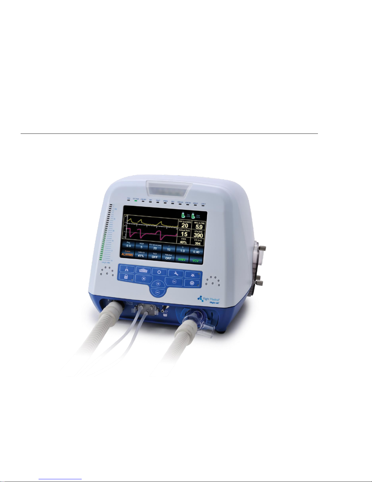
FLIGHT 60 VENTILATOR
Service Manual
Models: SL; DL; iO2
LIT-0021 Rev. A12 Aug 2016

TABLE OF CONTENTS
FLIGHT 60 Ventilator II

Legal Notice
ii | FLIGHT 60 Service Manual
Legal Notice
Disclaimer
FLIGHT MEDICAL INNOVATIONS Ltd. (FLIGHT MEDICAL) provides this Service Manual
in its commitment to help reduce patient risk and injury. However, this manual is not
intended to in any way replace or substitute duty of care to a patient, professional
responsibility, or professional judgment, nor is it intended to provide any warranty,
promise, guarantee, assumption of risk or duty, release, or indemnity. Physicians
shall at all times maintain responsibility for patient treatment and outcomes, and
FLIGHT MEDICAL further assumes no liability for patient treatment or outcome or for
physician's negligence, breach of duty of care, or malpractice.
The FLIGHT 60 Ventilator operator is solely responsible for selecting the appropriate
level and method of patient monitoring.
Product modification or misuse can be dangerous. FLIGHT MEDICAL disclaims all
liability for the consequences of product alterations or modifications, as well as for the
consequences which might result from the combination of this ventilator with other
products, whether supplied by FLIGHT MEDICAL or by other manufacturers, unless
such a combination has been specifically endorsed by FLIGHT MEDICAL.
The design of FLIGHT 60 Ventilator, the Operator’s and Service Manuals, and the
labeling on the ventilator, take into consideration that the purchase and use of the
equipment is restricted to trained professionals, and that certain inherent
characteristics of the ventilator are known to the operator. Instructions, warnings,
and caution statements are therefore limited to the specifics of the FLIGHT 60
Ventilator.
Federal law (US) restricts this device to sale by or on the order of a physician.
This Operator’s Manual excludes references to various hazards which are obvious to
medical professionals and operators of this equipment, to the consequences of
product misuse, and to potential adverse effects in patients with abnormal conditions.
When the FLIGHT 60 Ventilator is used in homecare and subacute environments, only
properly trained personnel should operate the ventilator. The FLIGHT 60 Ventilator is
a restricted medical device designed for use by respiratory therapists or other
properly trained and qualified personnel under the direction of a physician and in
accordance with applicable state laws and regulations.
Transport of patients with the FLIGHT 60 Ventilator requires that medical staff have a
good working knowledge of the ventilator’s use and problem resolution. Proper
emergency backup equipment must be immediately available during transport.
FLIGHT 60 Ventilator operators must recognize their responsibility for implementing
safety monitoring mechanisms which supply appropriate information on equipment
performance and patient condition. Patient safety may be achieved through a wide
variety of means, such as electronic surveillance of equipment performance and

Legal Notice
Flight 60 Service Manual | iii
patient condition. However, equipment surveillance should not replace direct
observation of clinical signs.
The liability of FLIGHT MEDICAL is subject to and limited to the exclusive terms and
conditions as set forth herein. Said liability is limited whether arising out of, or related
to, the manufacture and sale of goods, their installation, demonstration, sales
representation, use, performance, or otherwise. Any liability based upon product
warranty is limited regardless of any fault attributable to FLIGHT MEDICAL and the
nature of the action (including breach of warranty, negligence, and strict liability).
The written warranties are in lieu of all other warranties, expressed or implied,
including, without limitation, warranties of merchantability, fitness for any purpose, or
non-infringement.
FLIGHT MEDICAL shall not be liable for any special incidental or consequential
damages incurred by the buyer to a third party. The buyer shall not be entitled to
make liability recoveries from FLIGHT MEDICAL due to such situations.
Warranty
The FLIGHT 60 Ventilator warranty does not apply for/ in case of:
Defects caused by misuse, mishandling, tampering, or by modifications not
authorized by FLIGHT MEDICAL or its representatives.
Rubber and plastic components and materials, which are guaranteed to be free of
defects at time of delivery.
Any product which proves during the warranty period to be defective in workmanship
or material, will be replaced, credited, or repaired. FLIGHT MEDICAL retains the
discretion to select the most suitable of these options. FLIGHT MEDICAL is not
responsible for deterioration, wear, or abuse. In all cases, FLIGHT MEDICAL will not
be liable beyond the original selling price.
Application of this warranty is subject to the following conditions:
FLIGHT MEDICAL or its authorized representatives must be promptly notified
upon detection of the defective material or equipment.
Defective material or equipment must be returned to FLIGHT MEDICAL or its
authorized representative.
Examination by FLIGHT MEDICAL or its authorized representatives must confirm
that the defect is covered by the terms of this warranty.
To ensure complete protection under this warranty, the Warranty Registration Card
must be returned to a FLIGHT MEDICAL authorized representative within ten (10)
days of equipment receipt.
The above is the sole warranty provided by FLIGHT MEDICAL. No other warranty,
expressed or implied, is intended. Representatives of FLIGHT MEDICAL are not
authorized to modify the terms of this warranty.
In no way does this or any of FLIGHT MEDICAL policies, training materials, guidelines,
or instructions create an obligation for FLIGHT MEDICAL to perform any services.
About this Document
iv | FLIGHT 60 Service Manual
About this Document
This document is a service manual for the FLIGHT 60 and F60 Dual Limb Ventilators,
ventilators that provide continuous or intermittent mechanical ventilation support for
the care of individuals who require mechanical ventilation. It is intended for
technicians who are responsible for maintaining, servicing, and providing
troubleshooting assistance for the FLIGHT 60 and F60 Dual Limb Ventilators.
For information on how to use the FLIGHT 60 Ventilator, see the FLIGHT 60
Ventilator Operator's Manual.
Style Conventions
Convention
Used for
Verdana
Regular text.
Arial Bold
Names of labels, buttons, and other elements of the user interface.
Arial Italics
Special terms, the first time they appear.
Notes, which offer an additional explanation or a hint on how to overcome a
common problem.
Warnings, which indicate potentially damaging user operations and explain
how to avoid them.

Table of Contents
Flight 60 Service Manual | v
Table of Contents
1 INTRODUCTION ................................................................................. 1-1
INTENDED USE ................................................................................ 1-1
SYMBOLS ....................................................................................... 1-1
2 SAFETY INSTRUCTIONS ..................................................................... 2-1
GENERAL WARNINGS ......................................................................... 2-1
CAUTIONS ...................................................................................... 2-3
3 FUNCTIONAL DESCRIPTION ............................................................... 3-1
FRONT PANEL .................................................................................. 3-1
3.1.1 Keypad / Control Buttons ..................................................... 3-2
3.1.2 LED Indicators .................................................................... 3-3
LEFT SIDE PANEL .............................................................................. 3-4
RIGHT SIDE PANEL............................................................................ 3-5
BACK PANEL ................................................................................... 3-6
REMOTE ALARM CONNECTION ............................................................... 3-8
VENTILATOR MODULES ....................................................................... 3-9
VENTILATOR MODULES – IO
2
INTERNAL MIXER MODEL .................................. 3-10
PNEUMATIC DIAGRAM ....................................................................... 3-11
PNEUMATIC DIAGRAM – IO
2
INTERNAL MIXER MODEL ................................... 3-12
ELECTRICAL DIAGRAM ....................................................................... 3-13
ELECTRICAL DIAGRAM – IO
2
INTERNAL MIXER MODEL .................................. 3-14
4 REMOVING AND REINSTALLING MODULES ........................................ 4-1
INTRODUCTION ................................................................................ 4-1
REQUIRED EQUIPMENT ....................................................................... 4-1
REPLACING THE DETACHABLE BATTERY .................................................... 4-2
4.3.1 Removing the Detachable Battery ......................................... 4-2
4.3.2 Installing the Detachable Battery .......................................... 4-2
REPLACING THE INTERNAL BATTERY ........................................................ 4-2
4.4.1 Removing the Internal Battery .............................................. 4-2
4.4.2 Installing the Internal Battery ............................................... 4-3
REMOVING THE VENTILATOR COVER ........................................................ 4-3
4.5.1 Removing the Ventilator Cover ............................................. 4-3
4.5.2 Installing the Ventilator Cover .............................................. 4-6
REPLACING THE POWER BOARD ............................................................. 4-6
4.6.1 Removing the Power Board .................................................. 4-6
4.6.2 Installing the Power Board ................................................... 4-9

Table of Contents
vi | FLIGHT 60 Service Manual
REPLACING THE POWER SUPPLY ............................................................ 4-10
4.7.1 Class I Power Supply .......................................................... 4-10
4.7.2 Class II Power Supply ......................................................... 4-13
REPLACING THE FRONT PANEL ASSEMBLY ................................................ 4-14
4.8.1 Removing the Front Panel Assembly ..................................... 4-14
4.8.2 Connecting the Front Panel Assembly ................................... 4-17
REPLACING THE O
2
MIXER NEB BOARD * (IO2 INTERNAL MIXER MODEL ONLY) ...... 4-17
4.9.1 Removing the O2 mixer neb board ........................................ 4-17
4.9.2 Installing the O2 mixer board ............................................... 4-17
REPLACING THE MAIN BOARD .............................................................. 4-18
4.10.1 Removing the Main Board ................................................... 4-18
4.10.2 Installing the Main Board .................................................... 4-21
REPLACING THE TOUCH SCREEN ........................................................... 4-21
REPLACING THE MANIFOLD ASSEMBLY .................................................... 4-22
4.12.1 Removing the Manifold Assembly ......................................... 4-22
4.12.2 Installing the Manifold Assembly .......................................... 4-26
REPLACING THE OXYGEN SENSOR ......................................................... 4-27
4.13.1 Removing the Oxygen Sensor .............................................. 4-27
4.13.2 Installing the Oxygen Sensor ............................................... 4-28
REPLACING THE O
2
LEAK SENSOR * (IO2 INTERNAL MIXER MODEL ONLY) ............ 4-28
4.14.1 Removing the O2 leak sensor ............................................... 4-28
4.14.2 Installing the O2 leak sensor ................................................ 4-28
REPLACING THE OXYGEN MIXER * (IO
2
INTERNAL MIXER MODEL ONLY) .............. 4-29
4.15.1 Removing the Oxygen mixer ............................................... 4-29
4.15.2 Installing the Oxygen mixer ................................................ 4-30
REPLACING THE O
2
MIXER FILTERS * (IO
2
INTERNAL MIXER MODEL ONLY)........... 4-31
REPLACING THE PURGE BOARD ASSEMBLY ............................................... 4-31
4.17.1 Removing the Purge Board Assembly.................................... 4-31
4.17.2 Installing the Purge Board Assembly .................................... 4-32
REPLACING THE SOLENOID BOARD ASSEMBLY ........................................... 4-32
4.18.1 Removing the Solenoid Board Assembly ................................ 4-32
4.18.2 Installing the Solenoid Board Assembly................................. 4-33
REPLACING THE SOLENOID ASSEMBLY .................................................... 4-34
4.19.1 Removing the Solenoid Assembly ......................................... 4-34
4.19.2 Installing the Solenoid Assembly .......................................... 4-36
REPLACING THE LOWER BOARD AND D-TYPE BOARD .................................... 4-36
4.20.1 Removing the Lower Board and D-type Board ........................ 4-36
4.20.2 Installing the Lower Board and D-type Board ......................... 4-38
REPLACING THE FUSE ........................................................................ 4-39

Table of Contents
Flight 60 Service Manual | vii
4.21.1 Removing the Fuse............................................................. 4-39
4.21.2 Installing the Fuse ............................................................. 4-39
REPLACING THE RUBBER BUMPERS ........................................................ 4-40
4.22.1 Removing the Rubber Bumpers ............................................ 4-40
4.22.2 Installing the Rubber Bumpers ............................................. 4-40
5 SERVICE/TECHNICAL MENU............................................................... 5-1
ADVANCED SCREEN ........................................................................... 5-1
SERVICE SCREEN .............................................................................. 5-2
6 SOFTWARE UPGRADE ......................................................................... 6-4
INSTALLING THE SW UPGRADE .............................................................. 6-4
CALIBRATION INTEGRITY CHECK ............................................................. 6-4
7 CALIBRATION AND VERIFICATION TESTS ......................................... 7-6
REQUIRED EQUIPMENT ............................................................................... 7-6
CALIBRATION .................................................................................. 7-6
7.1.1 Pressure Relief Calibration .................................................... 7-6
7.1.2 Pressure Sensors Calibration ................................................ 7-7
7.1.3 Volume Factor Calibration ................................................... 7-10
7.1.4 Oxygen Sensor Calibration .................................................. 7-11
7.1.5 O2 Leak Sensor calibration* (iO2 Internal mixer model only) .... 7-12
OPERATIONAL VERIFICATION PROCEDURE (OVP) ....................................... 7-13
7.2.1 Standard Ventilator Settings (STS) ....................................... 7-13
7.2.2 Front Panel Self Test .......................................................... 7-13
7.2.3 Circuit Test ....................................................................... 7-14
7.2.4 Volume verification ............................................................ 7-15
7.2.5 Pressure Verification ........................................................... 7-15
7.2.6 PEEP ................................................................................ 7-16
7.2.7 Pressure Trigger ................................................................ 7-17
7.2.8 Exhalation Valve Leak ......................................................... 7-18
7.2.9 High Pressure Alarm ........................................................... 7-19
7.2.10 Battery /Charger /Power Supply .......................................... 7-19
7.2.11 Inlet Leak ......................................................................... 7-20
7.2.12 Buzzer Test ....................................................................... 7-21
7.2.13 Oxygen Calibration Test ...................................................... 7-21
7.2.14 Nebulizer compensation test * (iO2 Internal mixer model only) 7-22
7.2.15 OVP Test Results ................................................................ 7-23
TEST TABLE ................................................................................... 7-24
8 MAINTENANCE ................................................................................... 8-1
SCHEDULED MAINTENANCE ................................................................... 8-1
DOWNLOAD LOG FILES ....................................................................... 8-1
9 TROUBLESHOOTING GUIDE ............................................................... 9-3

Table of Contents
viii | FLIGHT 60 Service Manual
INTRODUCTION ................................................................................ 9-3
ERROR MESSAGES ............................................................................ 9-3
10 REPACKAGING AND SHIPPING ........................................................ 10-1
RGA RETURNS ....................................................................................... 10-1
11 SPARE PARTS ................................................................................... 11-2
ELECTRONIC .................................................................................. 11-2
MECHANICAL / ASSEMBLIES ................................................................ 11-5
CABLES ........................................................................................ 11-8
Introduction
Intended Use
Flight 60 Service Manual | 1-1
1 Introduction
This Service Manual (V60-00002-18 Rev. A) provides information for servicing the
FLIGHT 60 Ventilator. It is for use by authorized service personnel while installing,
servicing, and repairing the ventilator.
Intended Use
The FLIGHT 60 Ventilator is intended to provide continuous or intermittent
mechanical ventilation support for the care of individuals who require mechanical
ventilation. Specifically, the FLIGHT 60 Ventilator is applicable for adult and pediatric
patients, greater than or equal to 10 kg (22 lbs).
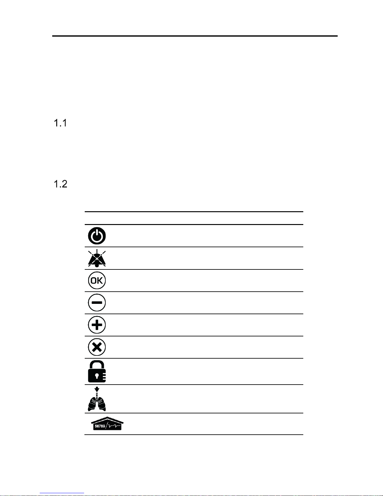
Symbols
Symbol
Description
Front Panel
On/Off
Alarm Reset
OK (Enter)
Decrease Button
Increase Button
Cancel
Panel Lock
Manual Breath
Parameters Screen
Introduction
Symbols
1-2 | FLIGHT 60 Service Manual
Symbol
Description
Extended Screen
Technical Screen
Nebulizer Port
Rear Panel
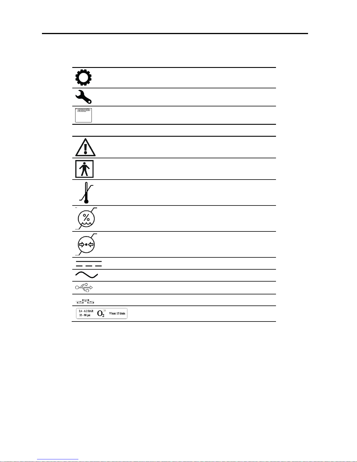
Caution; consult accompanying documents
Type BF applied part
Temperature limitation
Humidity limitation
Atmospheric pressure limitation
DC – Direct Current
AC – Alternating Current
USB – Universal Serial Bus
LAN – Local Area Network
High Pressure and Low-Flow Oxygen Port
Safety Instructions
General Warnings
Flight 60 Service Manual | 2-1
2 Safety Instructions
At all times, strictly follow this manual. The safe use of the FLIGHT 60 Ventilator
requires full understanding of its operation, and adherence to the manual's
instructions. The equipment is only to be used for the purpose specified in
section 1.1. Observe all of the WARNINGS and CAUTIONS posted in this manual, and
on buttons found on the FLIGHT 60 Ventilator and associated accessories.
General Warnings
External power connection: To maintain grounding integrity when using AC
power, only connect to grounded receptacles. Always disconnect the external
power prior to servicing. There is a risk of explosion if used in the presence of
flammable anesthetics.
All settings and adjustments in the different ventilation modes must be made
in accordance with a physician's prescribed therapy.
Do not use electrically conductive patient circuits.
Always use a clean, disinfected patient circuit.
Always use an outlet filter or equivalent at the Airway Pressure Connector, to
protect the internal sensors from moisture and other contaminants.
The ventilator is ready for operation only when:
1. It is completely assembled.
2. The OVP has been successfully completed.
Failure to identify and correct alarm violations may result in patient injury.
Safety Instructions
General Warnings
2-2 | FLIGHT 60 Service Manual
Ensure that the oxygen source is not empty before and during the use of the
optional Air/Oxygen Entrainment Mixer or Oxygen Blending Bag Kit.
As Li-Ion batteries are charged and discharged over time, their ability to hold a
charge is decreased with use. This can shorten the amount of time the
ventilator can function while on battery power.
The batteries should be replaced when the batteries no longer meet the needs
of the user. This depends on a number of factors including settings and usage
patterns.
Charge the batteries for a minimum of three hours before powering the
ventilator from the batteries. This provides fully charged batteries.
During storage, charge the batteries for a minimum of three hours every 30
days. This provides charged batteries.
Always ensure that the green Ext. Power LED is illuminated after connecting
the FLIGHT 60 Ventilator to an external AC or DC power source. If the LED is
not illuminated, check all power connections and resolve any problems.
Always plug the FLIGHT 60 Ventilator into an AC power supply source when not
in use, to ensure best battery performance.
The flow resistance of the air inlet filter, located on the right side of the
ventilator, is likely to increase with repeated use. Ensure that the filter is
changed regularly.
Only a FLIGHT MEDICAL approved patient circuit can be used with the FLIGHT
60 Ventilator.
Safety Instructions
Cautions
Flight 60 Service Manual | 2-3
Only a FLIGHT MEDICAL approved exhalation valve can be used with the
FLIGHT 60 Ventilator.
Perform a Circuit Test each time a clean circuit/exhalation valve is installed.
This FLIGHT 60 Ventilator has been tested and found to comply with the EMC
limits according to the EN60601-1-1-2 standard class B. These limits are
designed to provide reasonable protection against harmful interference in a
typical medical installation. The equipment generates uses and can radiate
radio frequency energy and, if not installed and used in accordance with these
instructions, may cause harmful interference to other devices in the vicinity.
However, there is no guarantee that interference will not occur in a particular
installation. If this equipment does cause harmful interference with other
devices, which can be determined by turning the equipment off and on, the
user is encouraged to try to correct the interference by one or more of the
following measures:
Reorient or relocate the receiving device.
Increase the distance between the equipment.
Connect the equipment into an outlet on a circuit different from that to which
the device (s) is connected.
Consult the manufacturer for help.
Cautions
Only use medical grade oxygen with the Air/Oxygen Entrainment Mixer or
Oxygen Blending Bag Kit.
Do not place liquid containers in the immediate vicinity or on top of the FLIGHT
60 Ventilator. Liquids that get into the ventilator can cause equipment
malfunction and damage.
After the FLIGHT 60 Ventilator is serviced, it must completely pass an
Operational Verification Procedure (OVP) before being returned to patient use.
Safety Instructions
Cautions
2-4 | FLIGHT 60 Service Manual
An authorized FLIGHT MEDICAL factory-trained technician must do all service
or repairs performed on the FLIGHT 60 Ventilator.
Do not open the ventilator or perform service on an open unit while connected
to external power.
Use standard antistatic techniques while working inside the ventilator or
handling any electronic parts.
Clean all external accessories of the ventilator prior to servicing.
Water in the oxygen supply can cause equipment malfunction and damage.
Batteries contain Li-Ion. Do not discard them in an incinerator or force them
open. Batteries should not be disposed of with normal waste.
Use the tools and equipment specified in this manual to perform specific
procedures.
Functional Description
Front Panel
Flight 60 Service Manual | 3-1
3 Functional Description
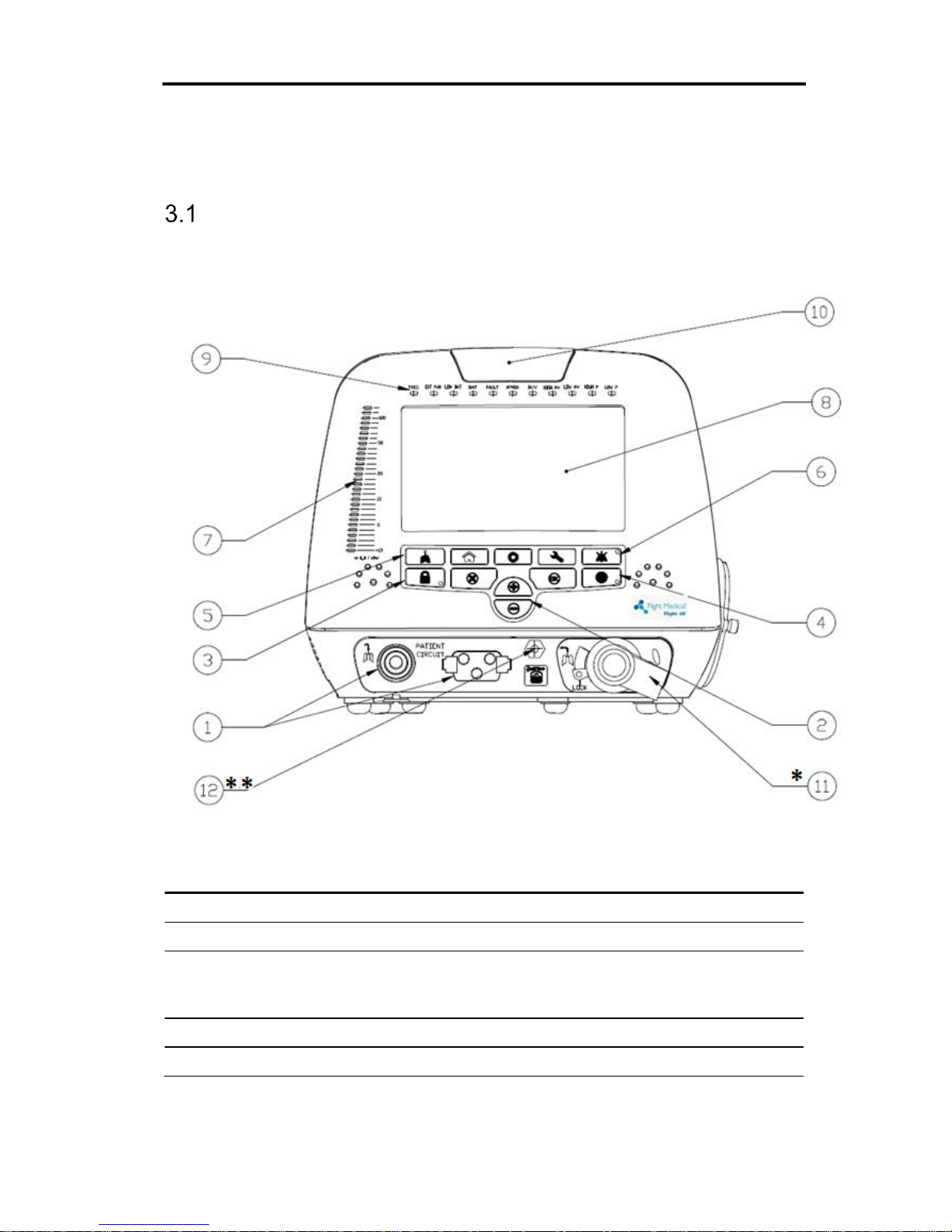
Front Panel
The front panel contains the control buttons, visual indicators, display screen, and
patient circuit connection. There are 2 types of keypad – symbols or print.
Figure 1 – Front Panel
Label
Name
Description
1
Patient Circuit Connector
Composed of a gas outlet and quick connector.
2
+/- button
Enables the user to adjust setting parameters.
3
Panel Lock button
Enables the user to lock the ventilator’s control, preventing
accidental changes. Pressing the button of a locked panel
and then Enter, unlocks the panel.
4
On/Off button
Turns the ventilator on or off, to start or stop ventilation.
5
Manual Breath button
Delivers a user initiated manual inflation.

Functional Description
Front Panel
3-2 | FLIGHT 60 Service Manual
Label
Name
Description
6
Audio Paused / Alarm Reset
button
Toggle button. Pressing Audio Paused temporarily silences
the audible alarm; pressing Alarm Reset clears lit alarm
LEDs.
7
Pressure Gauge
The pressure gauge is a visual indicator of breath activity,
which shows the dynamic movements of the breath
pressures. When a breath is being delivered, the user can
see the relative pressure and phase of the breath
(inspiration or expiration).
The pressure gauge is comprised of 29 LEDs. From -10 to
+20 cmH2O, each notch equals 2 cmH2O; from 20 to
50 cmH2O, each notch equals 5 cmH2O; above 50 cmH2O,
each notch equals 10 cmH2O.
8
Display touch screen
Enables the user to modify the ventilation, alarm, and
technical settings, and to view real time patient data,
alarms, battery status and logs.
9
LED Indicators
Inform the user of various events.
10
Primary Alarm LED
Flashes red to indicate that there is a high priority alarm.
11*
Dual Limb Exhalation Valve
(DL model only)
Connects the patient circuit expiratory limb.
12**
Nebulizer Port (iO2 Internal
mixer model only)
Connects to the pneumatic nebulizer.
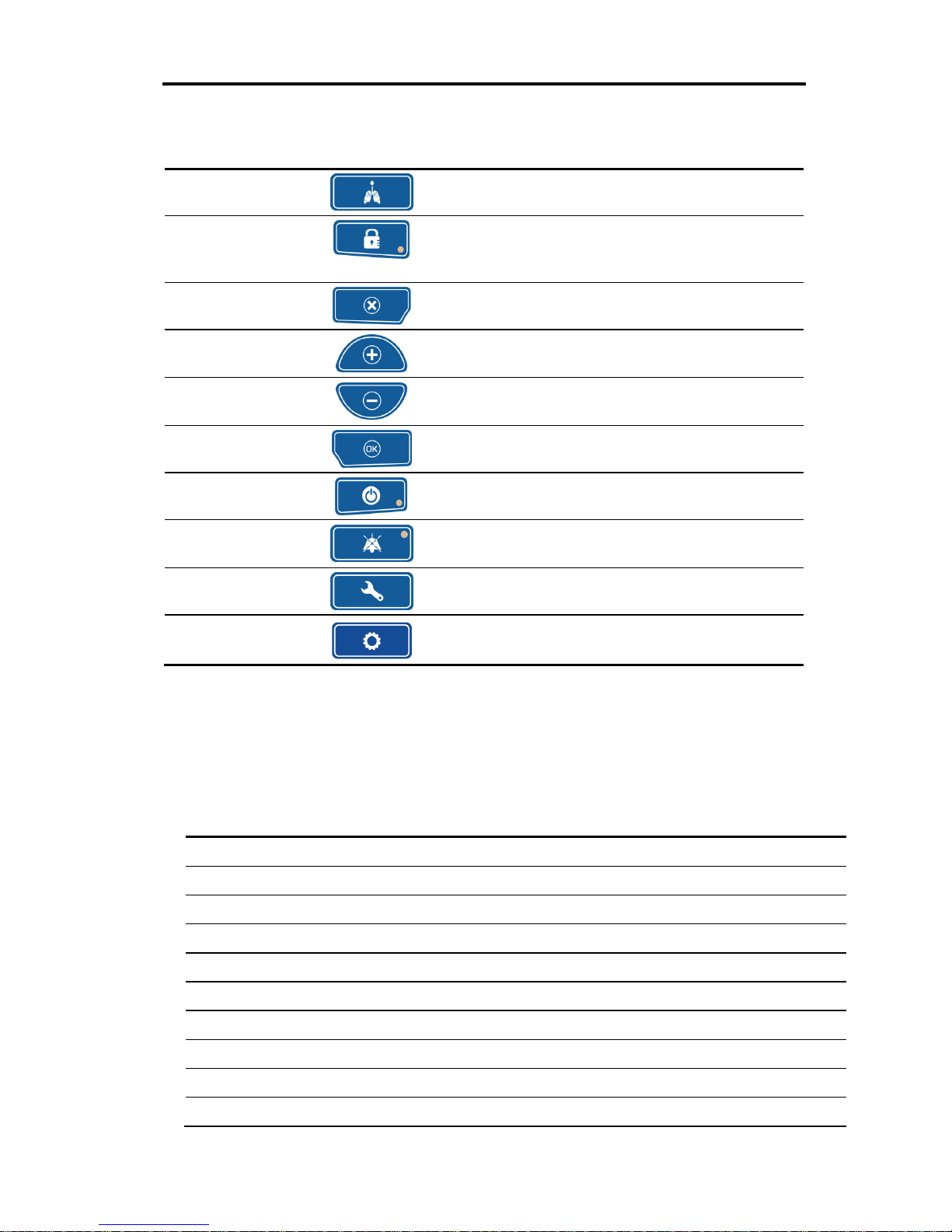
3.1.1 Keypad / Control Buttons
Figure 2 – Keypad / Control buttons
Item
Symbol
Description
1 – Parameters
(home)
The Parameters screen is the Flight 60's default screen.
Display switches automatically to Parameters from the
other screens if not operated for 30 seconds.
Use the Parameters button to toggle between the numeric
and the graphic displays.
Functional Description
Front Panel
Flight 60 Service Manual | 3-3
Item
Symbol
Description
2 - Manual Breath
Delivers a user initiated manual inflation.
3 – Panel Lock
Enables the user to lock the ventilator’s control,
preventing accidental changes. Pressing the button of a
locked panel and then Enter, unlocks the panel.
4 – Cancel
Enable the user to cancel parameters change.
5 – Increase
Button
Enables the user to adjust setting parameters upwards.
6 – Decrease
Button
Enables the user to adjust setting parameters
downwards.
7 – OK (Enter)
Enable the user to confirm parameters or mode change.
8 – On/Off
Turns the ventilator on or off, to start or stop ventilation.
9 – Alarm Reset
The Alarm Reset silences the audible alarm and clears lit
alarm LEDs.
10 – Technical
Technical data and selection options.
11 – Extended
Additional ventilation parameters screen.
3.1.2 LED Indicators
The LED indicators on the front panel inform the user of various events.
The following table describes the available LED indicators.
LED Indicator
Description
TRIG
Green LED indicates a patient’s breathing effort.
EXT PWR
Yellow LED indicates that an external power source is being applied to the ventilator.
LOW BAT
Red LED indicates that total batteries charge level is below 50%.
BAT
Orange LED indicates that the ventilator is powered on batteries.
FAULT
Red LED indicates a ventilator malfunction.
APNEA
Red LED indicates that no breaths have been delivered for the preset APNEA interval.
BUV
Red LED indicates that backup ventilation is active.
HIGH MV
Red LED indicates that the high inspiratory minute volume alarm limit is being violated.
LOW MV
Red LED indicates that the low inspiratory minute volume alarm limit is being violated.
HIGH P
Red LED indicates that the high peak airway pressure alarm limit is being violated.
Functional Description
Left Side Panel
3-4 | FLIGHT 60 Service Manual
LED Indicator
Description
LOW P
Red LED indicates low peak airway pressure.
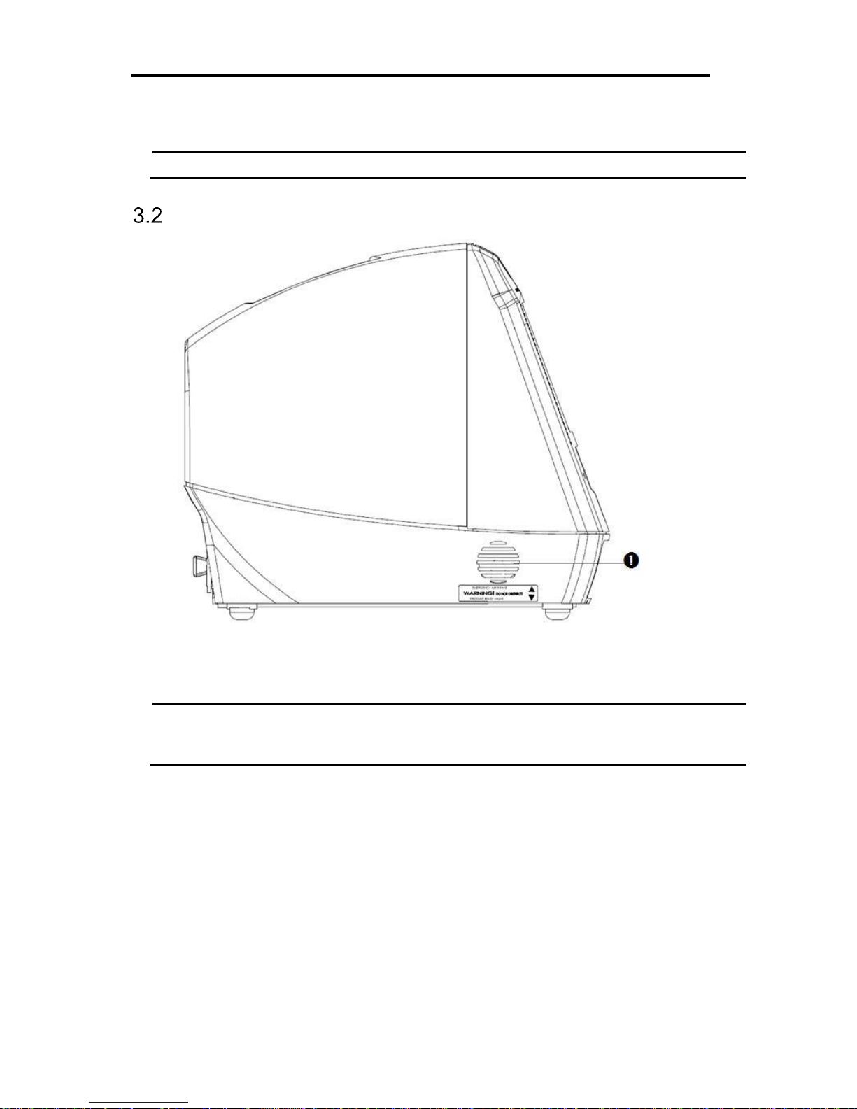
Left Side Panel
Figure 3 – Left Side Panel
Label
Name
Description
1
Emergency Air Intake
Enables the patient to pull ambient air into the patient circuit in the
event of a complete system failure. The Air Intake opening pressure
is approximately -3 cmH2O (-3 mbar).

Functional Description
Right Side Panel
Flight 60 Service Manual | 3-5
Right Side Panel
Figure 4 - Right Side Panel
Label
Name
Description
1
Fresh Gas Intake and
Filter Cover
Environmental air enters through this 30 mm ID Fresh Gas Intake.
The air inlet particle filter is placed behind the Filter Cover to protect
the patient as well as the ventilator’s piston system from dirt and
particles. The Fresh Gas Intake also serves as the attachment socket
for the optional FLIGHT 60 Ventilator Air/Oxygen Entrainment Mixer
or Oxygen Blending Bag.
Functional Description
Back Panel
3-6 | FLIGHT 60 Service Manual
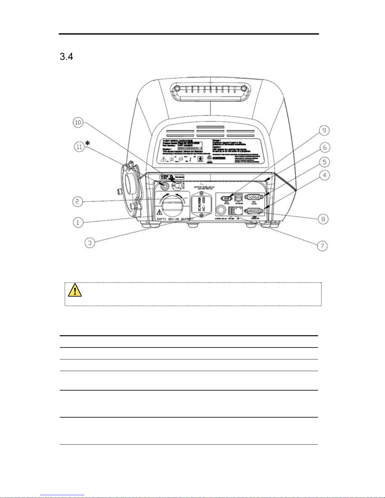
Back Panel
Figure 5 – Back Panel
To ensure proper grounding and prevent possible shock hazards, this device
should only be connected to grounded power receptacles.
Label
Name
Description
1
Detachable Battery
Li-Ion 14.8 VDC
2
AC Connector with Fuses
100 – 240 V AC, 50 – 60 Hz, Fuses 2x8A (time lag)
3
DC Connector
12 – 15 V DC
4
RS-232 Serial Port (COM2)
Remote alarm connector (Normally Open and Normally
Closed options).
5
RS-232 Serial Port (COM1)
Online output of events and error messages to the PC, using
a dedicated PCS2 protocol; for authorized and qualified
service technicians only.
6
USB B type
PC connector: USB port for downloading the main application
from the PC using a dedicated PCS2 protocol; for authorized
and qualified service technicians only.

Functional Description
Flight 60 Service Manual | 3-7
Label
Name
Description
7
USB A type
USB port for uploading LOG files to an external memory
stick; for authorized and qualified service technicians only.
8
LAN (RJ45)
LAN for network logging (currently not available).
9
Mini RS-485 (COM3)
For connecting FLIGHT MEDICAL peripherals. For future use.
10
Low Flow Oxygen Port
Low flow oxygen enrichment source.
11*
High Pressure O2 Port (iO
2
Internal mixer model only)
Connects to high pressure O2.
Functional Description
Remote Alarm Connection
3-8 | FLIGHT 60 Service Manual
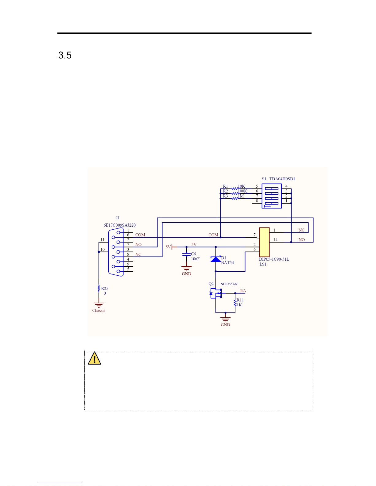
Remote Alarm Connection
The Flight-60 ventilator can be connected to third party remote alarm system.
The remote alarm station displays all visible and audible alarms and alerts if
the ventilator is shutdown.
Remote alarm cable should be connected to the COM2 RS232/RA port (the
lower port) in the back of the ventilator. The COM2 port provides a dry contact
output, both Normally Open (NO) and Normally Closed (NC).
Normally Open – Pin 7 – closing the contacts to transmit an alarm.
Normally Closed – Pin 8 – opening the contacts to transmit an alarm.
The dry contacts current should not exceed 1mA.
The voltage on the contacts must be lower than 12 Volts.
Remote Alarm Electrical schematics
The legal and regulatory responsibility for this integration of the Flight
60 device into any external system lays on the integrator and not the Flight
60 manufacturer. This include but is not limited to responsibilities for the
Design, Implementation, Installation validation verification and safety of
the connection of the Flight-60 to the remote alarm.
Falling to comply with the specification given here may result in damage to
the device and will void its warranty.
Functional Description
Ventilator Modules
Flight 60 Service Manual | 3-9
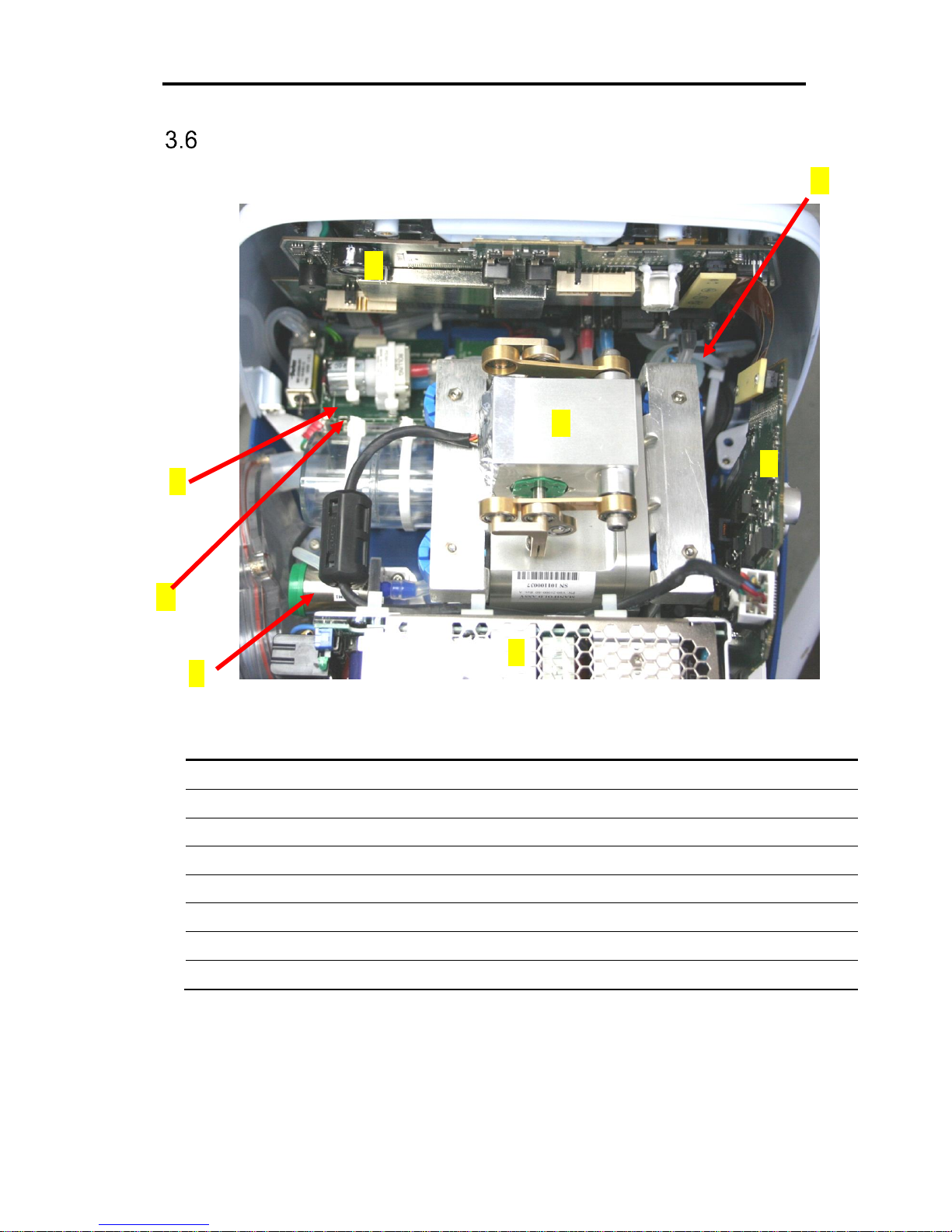
Ventilator Modules
Figure 6 – Ventilator Modules
#
Component
P/N A Main board (MB)
V60-60002-65
B
Power board (PB)
V60-21000-65
C
Power supply (PS)
V60-13000-65
D
Manifold assembly
V60-21000-60
E
Solenoid board assembly
V60-26000-65
F
Solenoid assembly
V60-21400-69
G
Oxygen (O2) Sensor
V60-25000-29
H
Purge board
V60-23000-65
A
B
C D F G E
H
Functional Description
Ventilator Modules – iO2 Internal mixer model
3-10 | FLIGHT 60 Service Manual
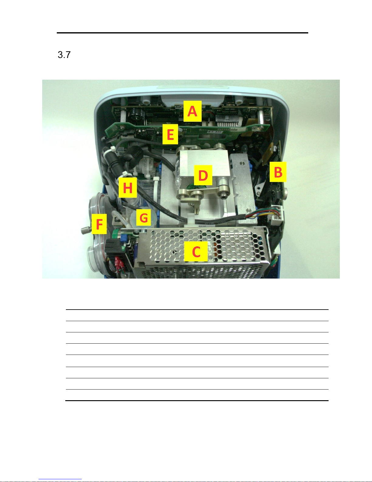
Ventilator Modules – iO2 Internal mixer model
Figure 7 – Ventilator Modules Internal Mixer
#
Component
P/N A Main board (MB)
V60-60002-65
B
Power board (PB)
V60-21000-65
C
Power supply (PS)
V60-13000-65
D
Manifold assembly
V60-21000-60
E
O2 Mixer Neb board
ELE-0001
F
Inlet assembly
V60-21400-69
G
O2 leak sensor
G60-25000-29
H
Internal O2 mixer
SUB-0101
Functional Description
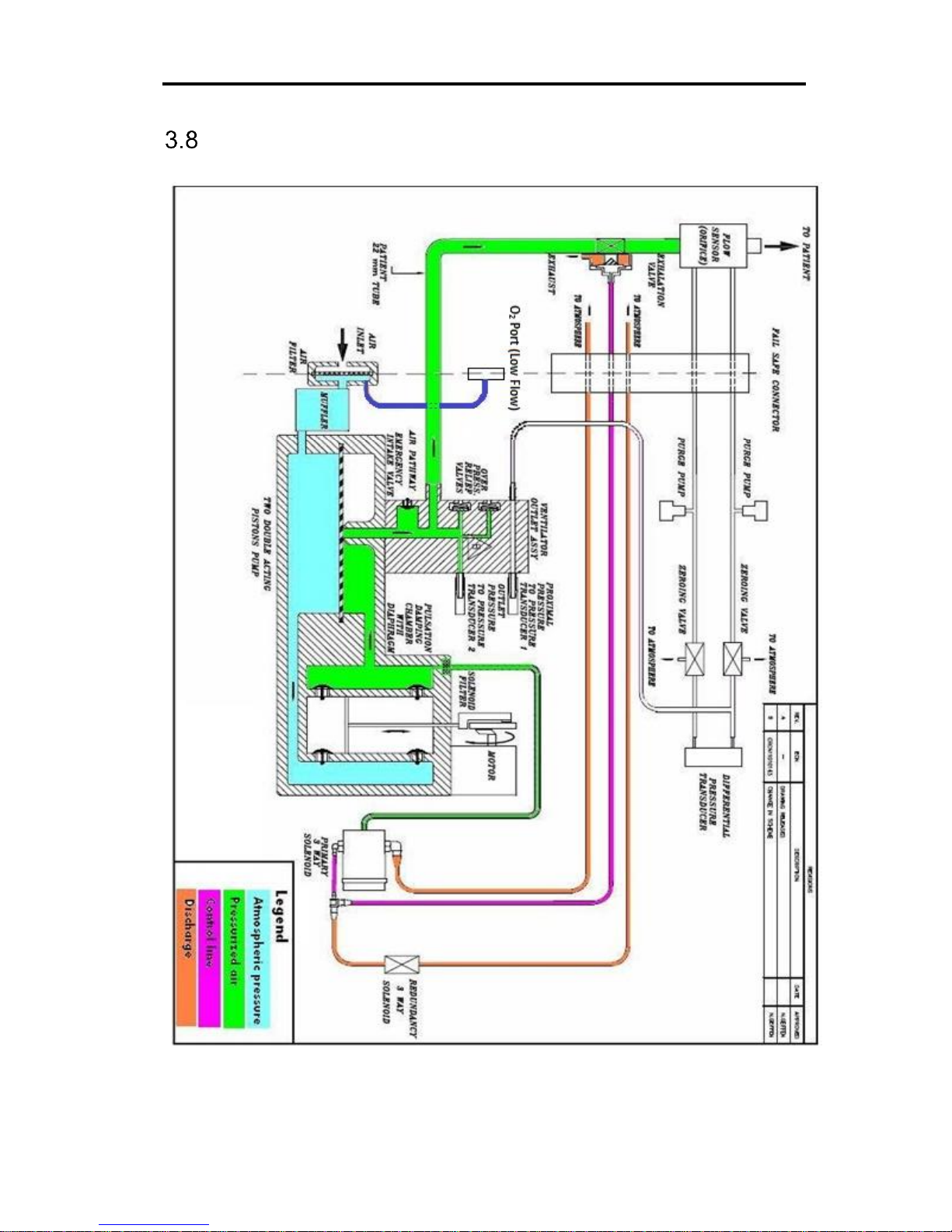
Pneumatic Diagram
Flight 60 Service Manual | 3-11
Pneumatic Diagram
Functional Description
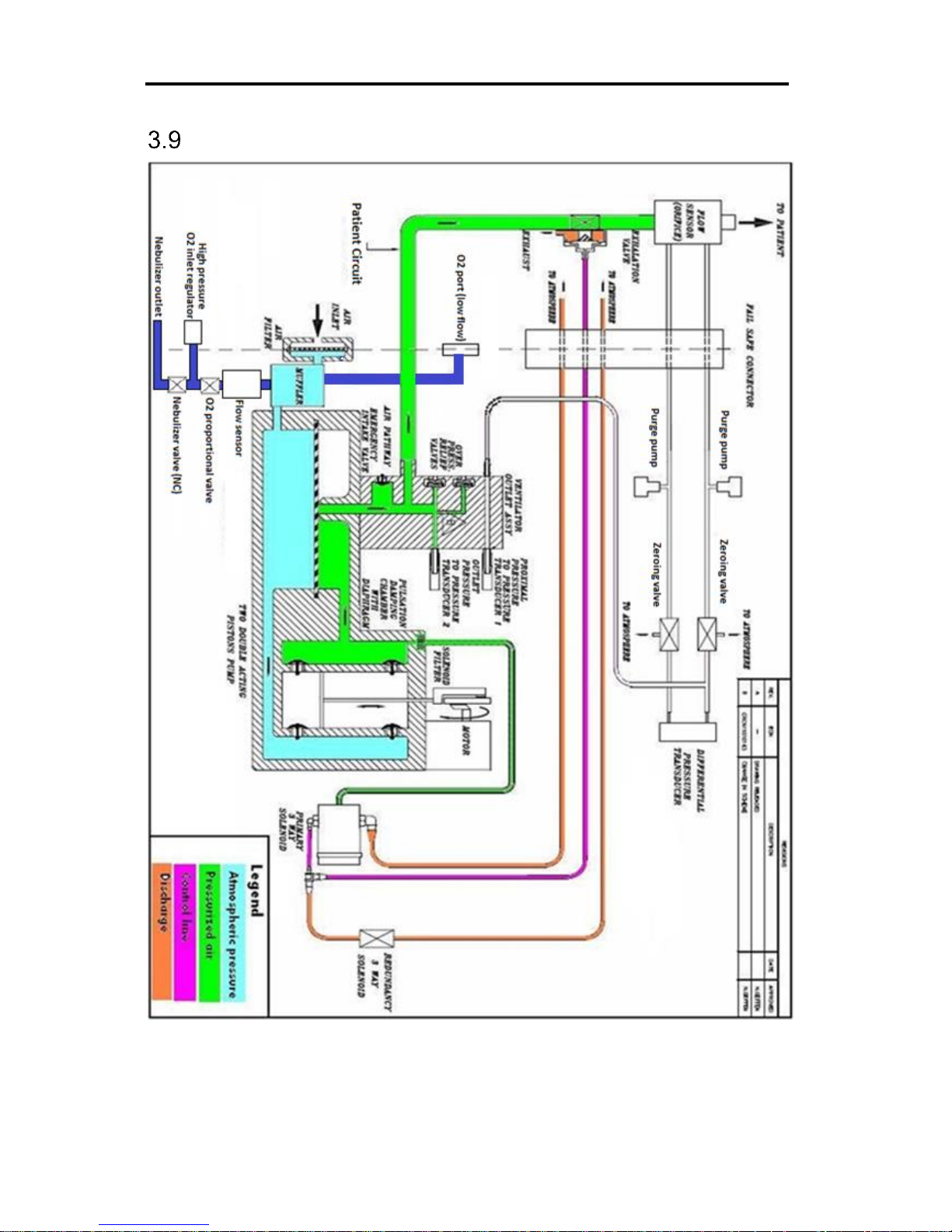
Pneumatic Diagram – iO2 Internal mixer model
3-12 | FLIGHT 60 Service Manual
Pneumatic Diagram – iO2 Internal mixer model
Functional Description
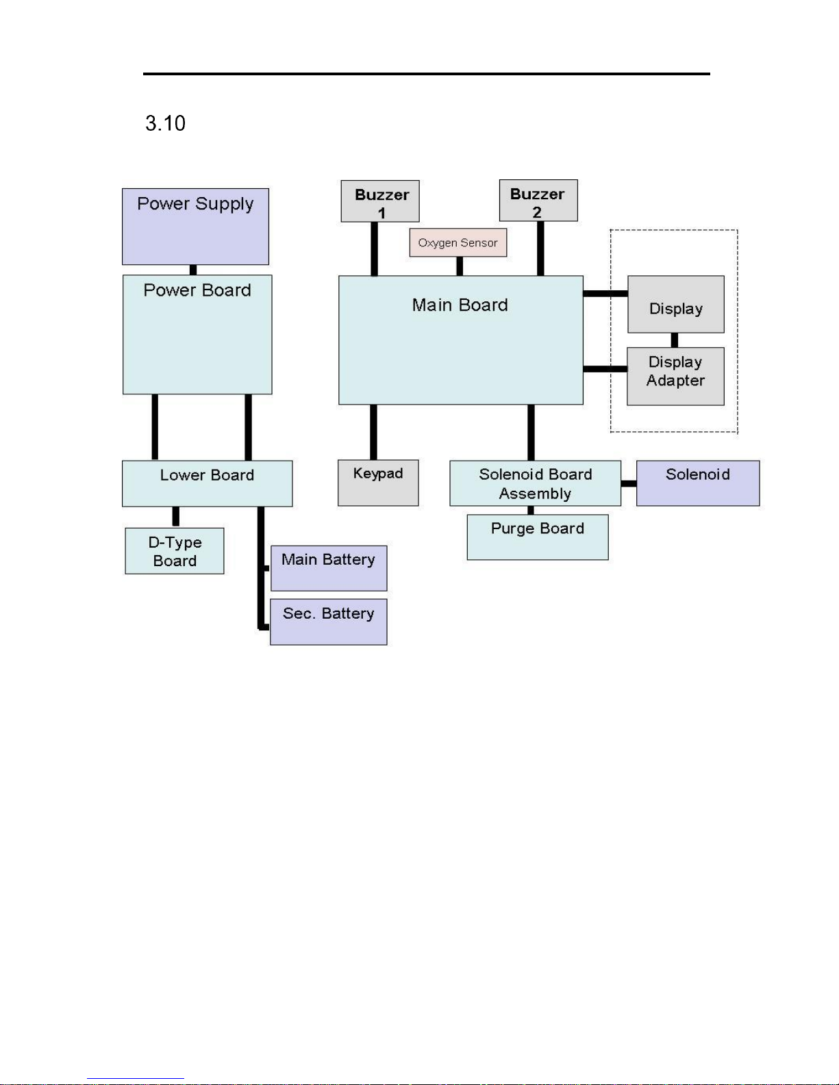
Electrical Diagram
Flight 60 Service Manual | 3-13
Electrical Diagram
Functional Description
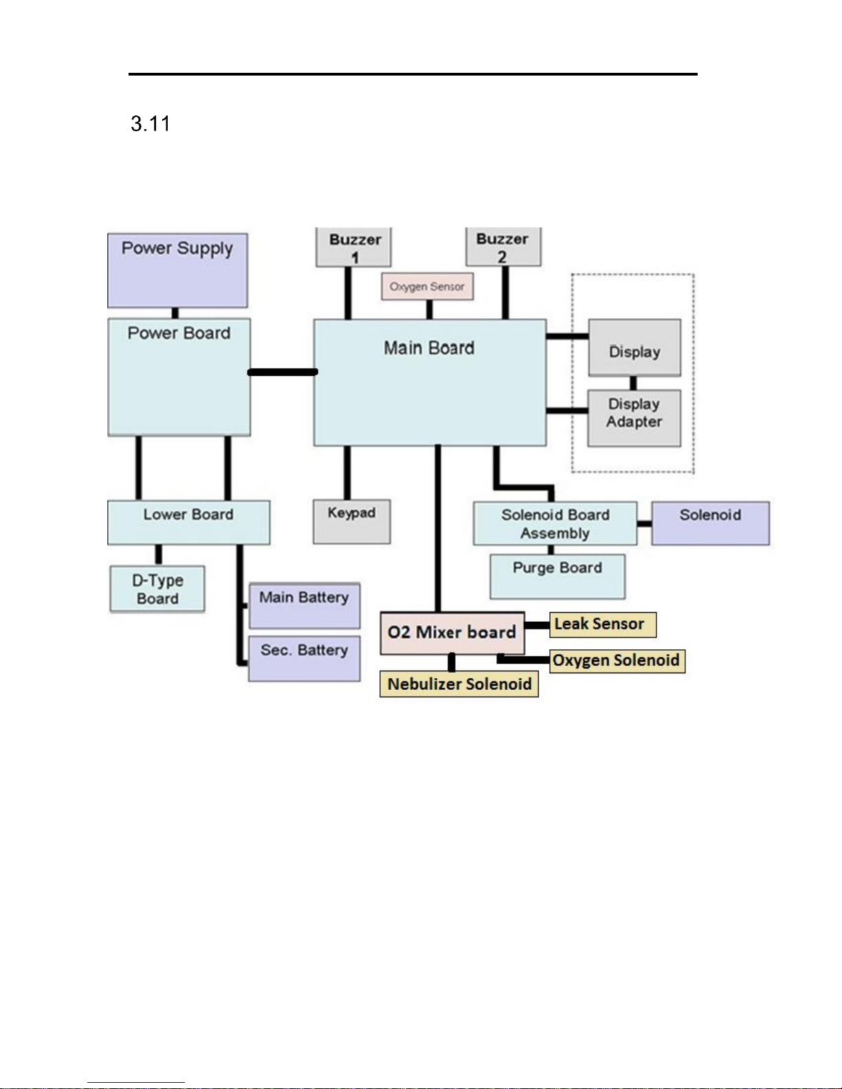
Electrical Diagram – iO2 Internal Mixer model
3-14 | FLIGHT 60 Service Manual
Electrical Diagram – iO2 Internal Mixer model
 Loading...