

Flight Medical Innovations FLIGHT 60 Operator's Manual
FLIGHT MEDICAL INNOVATIONS LTD.
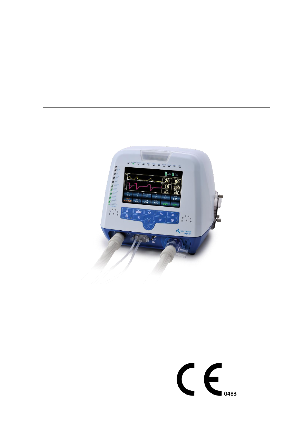
FLIGHT 60 Turbine
Ventilator
Operator's Manual SW Ver 4.25
LIT-0089 Rev. A03 OPERATING MANUAL-FLIGHT60 TURBINE SYMBOL
KEYPAD WITH OPTIONAL INTERNAL O2 MIXER


Legal Notice
Operator's Manual | i
Federal law (US) restricts this device to sale by or on the
order of a physician.
Legal Notice
Disclaimer
FLIGHT MEDICAL INNOVATIONS LTD. (FLIGHT MEDICAL) provides this
Operator’s Manual in its commitment to help reduce patient risk and injury.
However, this manual is not intended to in any way replace or substitute duty
of care to a patient, professional responsibility, or professional judgment, nor
is it intended to provide any warranty, promise, guarantee, assumption of risk
or duty, release, or indemnity. Physicians shall at all times maintain
responsibility for patient treatment and outcomes, and FLIGHT MEDICAL
further assumes no liability for patient treatment or outcome or for physician's
negligence, breach of duty of care, or malpractice.
The FLIGHT 60 Ventilator operator is solely responsible for selecting the
appropriate level and method of patient monitoring. Product modification or
misuse can be dangerous. FLIGHT MEDICAL disclaims all liability for the
consequences of product alterations or modifications, as well as for the
consequences which might result from the combination of this ventilator with
other products, whether supplied by FLIGHT MEDICAL or by other
manufacturers, unless such a combination has been specifically endorsed by
FLIGHT MEDICAL.
The design of FLIGHT 60 Ventilator, the Operator’s and Service Manuals, and
the labeling on the ventilator, take into consideration that the purchase and
use of the equipment is restricted to trained professionals, and that certain
inherent characteristics of the ventilator are known to the operator.
Instructions, warnings, and caution statements are therefore limited to the
specifics of the FLIGHT 60 Ventilator.
This Operator’s Manual excludes references to various hazards which are
obvious to medical professionals and operators of this equipment, to the
consequences of product misuse, and to potential adverse effects in patients
with abnormal conditions.
When the FLIGHT 60 Ventilator is used in homecare, hospitals, EMS and subacute environments, only properly trained personnel should operate the
ventilator. The FLIGHT 60 Ventilator is a restricted medical device designed for
use by respiratory therapists or other properly trained and qualified personnel
under the direction of a physician and in accordance with applicable state laws
and regulations.
Transport of patients with the FLIGHT 60 Ventilator requires that medical staff
have a good working knowledge of the ventilator’s use and problem resolution.
Proper emergency backup equipment must be immediately available during
transport.

Legal Notice
ii | Flight 60
FLIGHT 60 Ventilator operators must recognize their responsibility for
implementing safety monitoring mechanisms which supply appropriate
information on equipment performance and patient condition. Patient safety
may be achieved through a wide variety of means, such as electronic
surveillance of equipment performance and patient condition. However,
equipment surveillance should not replace direct observation of clinical signs.
The liability of FLIGHT MEDICAL is subject to and limited to the exclusive
terms and conditions as set forth herein. Said liability is limited whether
arising out of, or related to, the manufacture and sale of goods, their
installation, demonstration, sales representation, use, performance, or
otherwise. Any liability based upon product warranty is limited regardless of
any fault attributable to FLIGHT MEDICAL and the nature of the action
(including breach of warranty, negligence, and strict liability).
The written warranties are in lieu of all other warranties, expressed or implied,
including, without limitation, warranties of merchantability, fitness for any
purpose, or non-infringement.
FLIGHT MEDICAL shall not be liable for any special incidental or consequential
damages incurred by the buyer to a third party. The buyer shall not be entitled
to make liability recoveries from FLIGHT MEDICAL due to such situations.
Warranty
The FLIGHT 60 Ventilator warranty does not apply for/ in case of:
Defects caused by misuse, mishandling, tampering, or by
modifications not authorized by FLIGHT MEDICAL or its
representatives.
Rubber and plastic components and materials, which are guaranteed
to be free of defects at time of delivery.
Any product which proves during the warranty period to be defective in
workmanship or material, will be replaced, credited, or repaired. FLIGHT
MEDICAL retains the discretion to select the most suitable of these options.
FLIGHT MEDICAL is not responsible for deterioration, wear, or abuse. In all
cases, FLIGHT MEDICAL will not be liable beyond the original selling price.
Application of this warranty is subject to the following conditions:
FLIGHT MEDICAL or its authorized representatives must be promptly
notified upon detection of the defective material or equipment.
Defective material or equipment must be returned to FLIGHT
MEDICAL or its authorized representative.
Examination by FLIGHT MEDICAL or its authorized representatives
must confirm that the defect is covered by the terms of this
warranty.
The above is the sole warranty provided by FLIGHT MEDICAL. No other
warranty, expressed or implied, is intended. Representatives of FLIGHT
MEDICAL are not authorized to modify the terms of this warranty.

About this Document
Operator's Manual | iii
#
Chapter Name
Contents
Page
1
Introduction
Describes the intended use of the ventilator, symbols
appearing on the ventilator, and an overview of how
the ventilator works.
Pg. 1-1
2
Safety Instructions
Lists WARNINGS and CAUTIONS to be adhered to, in
order to safely use the ventilator.
Pg. 2-1
3
Ventilator
Description
Provides a detailed description of the front, back, left,
and right side panels of the ventilator.
Pg. 3-1
4
Installation
Describes how to remove the ventilator parts from the
box, mount the ventilator, plug it in, attach the patient
circuit, and install the oxygen accessories.
Pg. 4-1
5
Basic Operation
Describes the basic operation of the ventilator,
including how to turn the ventilator on or off, initiate
ventilation, navigate between screens, set control
values, cancel or accept parameter adjustments, and
change parameter values.
Pg. 5-1
6
Ventilator Settings
Describes the buttons on the Home, Extended, Alarms,
and Technical Screens
Pg. 6-1
7
Ventilator Alarms
and Backup
Ventilation
Describes the audible and visual alarm and caution
signals, displays the alarm and caution specifications,
provides instructions for silencing audible alarms,
resetting alarms, and setting up a remote alarm
Pg. 7-1
8
Monitoring
Describes the numeric and graphic displays used for
monitoring a patient's ventilation.
Pg. 8-1
9
Ventilation Modes
Describes the ventilation modes
Pg. 9-1
10
Special Functions
Describes the following special functions: nebulizer,
100% O2, SIGH, manual breath, panel lock, QuickStart, In-use O2 sensor calibration, Altitude
Compensation.
Pg. 10-1
In no way does this or any of FLIGHT MEDICAL's policies, training materials,
guidelines, or instructions create an obligation for FLIGHT MEDICAL to perform
any services.
About this Document
This document contains information intended to ensure safe and effective use
of the FLIGHT 60 Ventilator.

About this Document
iv | Flight 60
#
Chapter Name
Contents
Page
Err
or!
Re
fer
en
ce
so
ur
ce
no
t
fo
un
d.
Error! Reference source
not found.
Describes the oxygen blending bag kit accessories
Pg.
Error!
Bookm
ark not
defined
.
11
Cleaning and
Maintenance
Describes how to clean and disinfect the ventilator
parts, and how to maintain the ventilator.
Pg. 11-1
12
Troubleshooting
Describes problems that may arise, their probable
cause, and possible solutions. Also includes contact
information for technical support.
Pg. 12-1
14
Ventilator Quick
Check Procedure
Describes the testing procedures.
Pg. 14-1
15
Technical
Specifications
Describes the technical specifications for: hardware,
safety, environmental and oxygen accessories.
Pg. 15-1

Table of Contents
Operator's Manual | v
Table of Contents
1 INTRODUCTION ................................................................................. 1-1
1.1 INTENDED USE ................................................................................ 1-1
1.2 SYMBOLS ....................................................................................... 1-2
2 SAFETY INSTRUCTIONS ..................................................................... 2-1
2.1 GENERAL WARNINGS ......................................................................... 2-1
2.2 CAUTIONS ...................................................................................... 2-4
3 VENTILATOR DESCRIPTION ............................................................... 3-1
3.1 FRONT PANEL FEATURES ..................................................................... 3-1
3.1.1 Control Buttons .................................................................. 3-2
3.1.2 LED Indicators .................................................................... 3-3
3.2 BACK PANEL FEATURES ....................................................................... 3-4
3.3 LEFT SIDE PANEL FEATURES ................................................................. 3-5
3.4 RIGHT SIDE PANEL FEATURES ............................................................... 3-6
4 INSTALLATION .................................................................................. 4-1
4.1 INTRODUCTION ................................................................................ 4-1
4.2 REMOVING THE VENTILATOR PARTS FROM THE BOX ...................................... 4-1
4.3 MOUNTING THE VENTILATOR ................................................................ 4-1
4.4 INSTALLING THE DETACHABLE AND INTEGRAL BATTERIES ............................... 4-2
4.5 PLUGGING IN THE POWER CORD (FOR AC) ................................................ 4-2
4.6 ATTACHING THE PATIENT CIRCUIT .......................................................... 4-3
4.7 CIRCUIT TEST ................................................................................. 4-4
4.8 CONNECTING THE OXYGEN SUPPLY ......................................................... 4-5
4.8.1 Internal O2 Mixer ................................................................. 4-6
4.8.2 Low-Flow Oxygen Port ......................................................... 4-6
5 BASIC OPERATION ............................................................................. 5-1
5.1 POWERING ON THE VENTILATOR ............................................................ 5-1
5.2 INITIATING VENTILATION .................................................................... 5-2
5.3 TURNING OFF THE VENTILATOR ............................................................. 5-2
5.4 NAVIGATING BETWEEN SCREENS ........................................................... 5-3
5.5 SETTING CONTROL VALUES .................................................................. 5-3
5.5.1 Default and Saved Values .................................................... 5-4
6 VENTILATOR SETTINGS ..................................................................... 6-1
6.1 HOME (PARAMETERS) SCREEN .............................................................. 6-1
6.1.1 Pop-Up Messages ................................................................ 6-6
6.2 EXTENDED SCREEN ........................................................................... 6-8
6.3 ALARMS SCREEN ............................................................................. 6-10

Table of Contents
vi | Flight 60
6.4 TECHNICAL SCREEN .......................................................................... 6-11
7 VENTILATOR ALARMS AND BACKUP VENTILATION ............................ 7-1
7.1 AUDIBLE ALARM AND CAUTION SIGNALS .................................................. 7-1
7.2 VISUAL ALARM AND CAUTION SIGNALS .................................................... 7-2
7.3 ALARM AND CAUTION SPECIFICATIONS .................................................... 7-3
7.3.1 Variable Ventilation Alarms................................................... 7-3
7.3.2 Automatic Ventilation Alarms ................................................ 7-4
7.3.3 Automatic Technical Alarms .................................................. 7-5
7.3.4 Cautions (Low Priority) ........................................................ 7-6
7.4 APNEA BACKUP VENTILATION ................................................................ 7-7
7.4.1 Backup Ventilation in ACMV and SIMV Modes.......................... 7-8
7.4.2 Backup Ventilation in SPONT, MVG and VTG Modes ................. 7-8
7.4.3 Backup Ventilation in B-LEV Mode ......................................... 7-8
7.4.4 Cancellation of Backup Ventilation ......................................... 7-8
7.4.5 Customized BUV ................................................................. 7-8
7.5 LOW POWER VENTILATION (LPV) .......................................................... 7-9
7.5.1 Cancellation of LPV Ventilation .............................................. 7-9
7.6 SILENCING AUDIBLE ALARMS ............................................................... 7-10
7.7 RESETTING ALARMS ......................................................................... 7-10
7.8 DISABLING THE CHECK CIRCUIT ALARM .................................................. 7-10
7.9 DISABLING THE LOW P ALARM ............................................................ 7-11
7.10 SETTING UP A REMOTE ALARM ............................................................. 7-12
8 MONITORING ..................................................................................... 8-1
8.1 GRAPHIC DISPLAY ............................................................................. 8-1
8.1.1 Waveforms and Loops ......................................................... 8-1
8.1.2 Trends ............................................................................... 8-2
8.1.3 Selecting Trended Parameters .............................................. 8-3
8.1.4 Time Scale Adjustment ........................................................ 8-3
8.2 LUNG MECHANICS MONITORING DISPLAY ................................................. 8-3
8.2.1 Lung Mechanics Monitoring Display ....................................... 8-4
8.3 RSBI MONITORING ........................................................................... 8-5
8.4 ADDITIONAL MONITORING PARAMETERS DISPLAY ......................................... 8-5
8.5 NUMERIC DISPLAY ............................................................................ 8-6
9 VENTILATION MODES ........................................................................ 9-1
9.1 ACMV MODE (ASSIST/CONTROL MANDATORY VENTILATION) ......................... 9-1
9.2 SIMV MODE (SYNCHRONIZED INTERMITTENT MANDATORY VENTILATION) ........... 9-1
9.2.1 VC/PC/PRVC ....................................................................... 9-2
9.3 SPONT MODE (SPONTANEOUS VENTILATION) ........................................... 9-7
9.4 VG (VOLUME GUARANTEE) .................................................................. 9-7
9.5 B-LEV MODE (BI-PHASIC VENTILATION) ................................................ 9-10

Table of Contents
Operator's Manual | vii
9.6 NIV (NON-INVASIVE VENTILATION) SUB MODE AUTO-ALARM FUNCTION ........... 9-11
10 SPECIAL FUNCTIONS ....................................................................... 10-1
10.1 NEBULIZER (OPTIONAL) .................................................................. 10-1
10.2 2 MINUTES 100% O2 (OPTIONAL) .................................................... 10-2
10.3 SIGH .......................................................................................... 10-2
10.4 MANUAL BREATH ............................................................................. 10-3
10.5 PANEL LOCK .................................................................................. 10-3
10.6 QUICK-START AND PRESET VENTILATION CONFIGURATIONS .......................... 10-4
10.6.1 Quick-Start: Factory default settings .................................... 10-5
10.6.2 Setting and loading the preset ventilation configurations ......... 10-5
10.7 IN-USE O
SENSOR CALIBRATION ......................................................... 10-6
2
10.8 ALTITUDE COMPENSATION .................................................................. 10-8
11 CLEANING AND MAINTENANCE ........................................................ 11-1
11.1 CLEANING AND DISINFECTING ............................................................. 11-1
11.1.1 FLIGHT 60 Ventilator .......................................................... 11-1
11.1.2 FLIGHT 60 Ventilator Accessories ......................................... 11-2
11.2 MAINTENANCE ................................................................................ 11-7
11.2.1 Preventive Maintenance ...................................................... 11-7
11.2.2 O2 Sensor Maintenance ....................................................... 11-8
11.2.3 Internal Battery Maintenance .............................................. 11-8
11.2.4 25,000 Hour Maintenance ................................................... 11-8
11.3 GENERAL WARNINGS ........................................................................ 11-9
12 TROUBLESHOOTING ......................................................................... 12-1
12.1 INTRODUCTION ............................................................................... 12-1
12.2 ALARMS ........................................................................................ 12-1
12.3 GENERAL/CLINICAL .......................................................................... 12-5
12.4 OXYGEN ENRICHMENT ....................................................................... 12-9
13 CONTACT INFORMATION ............................................................... 13-10
14 VENTILATOR QUICK CHECK PROCEDURE ......................................... 14-1
14.1 INTRODUCTION ............................................................................... 14-1
14.1.1 Setting Up the Ventilator for the Test ................................... 14-1
14.2 QUICK CHECK PROCEDURE ................................................................. 14-2
14.2.1 Checking the Power Management ......................................... 14-2
14.2.2 Checking the Alarms .......................................................... 14-3
14.2.3 Checking the Monitored Parameters ..................................... 14-3
14.3 CHECK-OFF SHEET........................................................................... 14-4
15 TECHNICAL SPECIFICATIONS .......................................................... 15-1
15.1 PHYSICAL SPECIFICATIONS ................................................................. 15-1
15.2 PNEUMATIC SPECIFICATIONS ............................................................... 15-1

Table of Contents
viii | Flight 60
15.3 ELECTROMAGNETIC EMISSION - GUIDANCE AND MANUFACTURER'S DECLARATION . 15-1
15.3.1 Recommended separation distance between portable Mobile
RF communications Equipment and the device ....................... 15-5
15.3.2 Recommended Separation Distances Between Power Buses
and the Product ................................................................. 15-6
15.3.3 EMC statement of Essential Performance ............................... 15-6
15.4 ELECTRICAL SPECIFICATIONS ............................................................... 15-7
15.5 INTERNAL BATTERY SPECIFICATIONS ...................................................... 15-7
15.6 SAFETY AND PARTICULAR STANDARD SPECIFICATIONS ................................. 15-8
15.7 ENVIRONMENTAL SPECIFICATIONS ......................................................... 15-8
15.8 INTERNAL O2 MIXER ........................................................................ 15-9
15.9 OXYGEN BLENDING BAG KIT SPECIFICATIONS ........................................... 15-9
15.10 LOW FLOW PORT OXYGEN SPECIFICATIONS .................................. 15-10
15.11 INTERNAL OXYGEN SENSOR SPECIFICATIONS ................................ 15-10
16 INDEX ............................................................................................ 16-11

Operator's Manual | 1-1
1 Introduction
Transport of patients with the FLIGHT 60 Ventilator requires that
medical staff have a good working knowledge of the ventilator’s
use and problem resolution. Proper emergency backup equipment
must be immediately available during transport.
The FLIGHT 60 Ventilator is an electrically powered, microprocessor-controlled
ventilator with pressure support for spontaneous breathing. It can be pressure
or time activated, volume or pressure limited, and time, pressure, or flow
cycled. Backup ventilation is available, manual inflation is possible, and there
is an emergency intake valve which allows the patient to pull ambient air into
the patient circuit in the event of a complete loss of supply of gas pressure.
Opening pressure is approximately –3 cmH2O (–3 mbar) during emergency
intake.
The FLIGHT 60 Ventilator may be powered by external power (100-240 VAC or
12-15 VDC) or by its Li Ion internal batteries. Two internal Li Ion rechargeable
batteries power the ventilator for up to 8 hours when fully charged.
The main component of the pneumatic system is an electrically controlled
pump. This pump provides a compressed gas source so that no external air
compressor is needed. Additionally, the exhalation valve is activated by an
electrically controlled proportional solenoid.
Introduction
This Operator’s Manual (LIT-0089) contains information intended to ensure
safe and effective use of the FLIGHT 60 Ventilator.
1.1 Intended Use
The FLIGHT 60 Ventilator is intended to provide continuous or intermittent
mechanical ventilation support for the care of individuals who require
mechanical ventilation. Specifically, the FLIGHT 60 is applicable for adult and
pediatric (i.e., infant, child and adolescent) patients who weigh at least 5 kg
(11 lbs).
The FLIGHT 60 Ventilator is a restricted medical device intended for use by
qualified, trained personnel under the direction of a physician; it is suitable for
use in hospitals, sub-acute emergency rooms, and home care environments,
as well as for transport and emergency response applications.
Introduction
1-2 | Flight 60
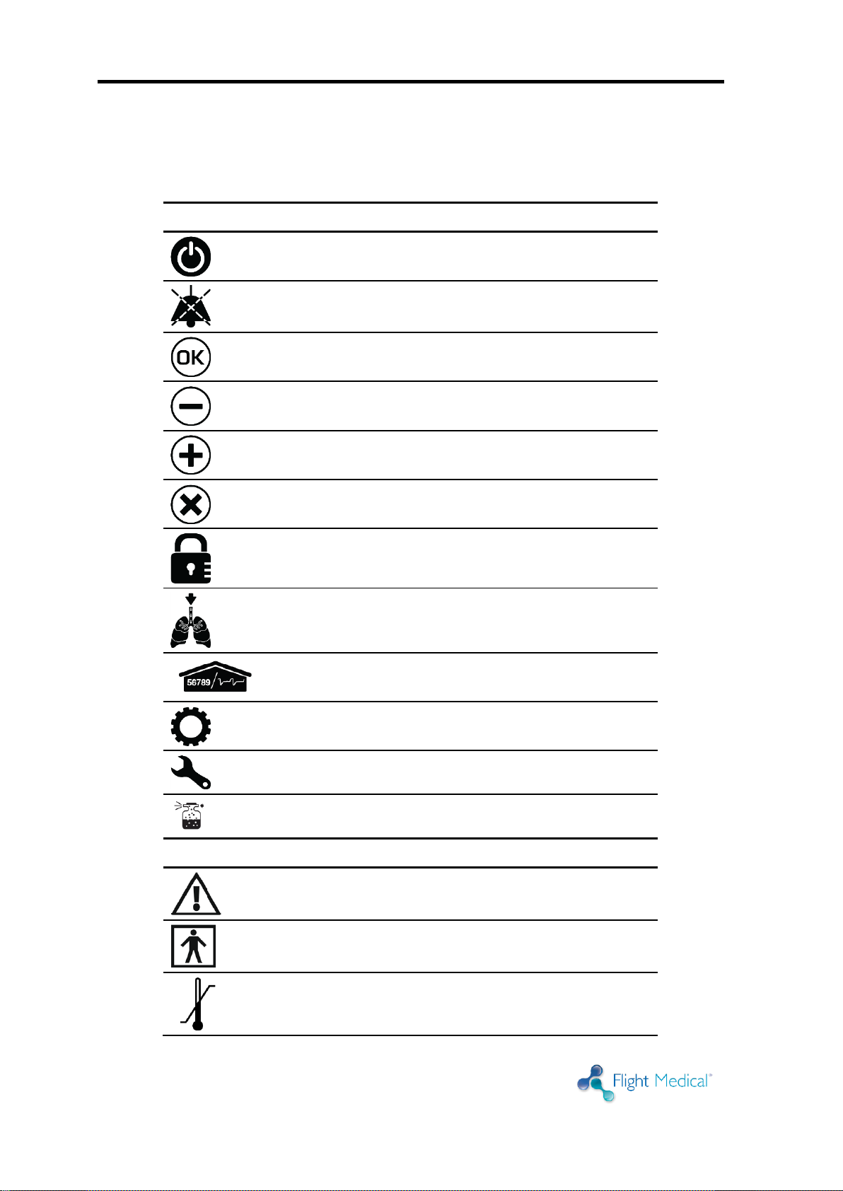
Symbol
Description
Front Panel
On/Off
Alarm Reset
OK (Enter)
Decrease Button
Increase Button
Cancel
Panel Lock
Manual Breath
Parameters Screen
Extended Screen
Technical Screen
Nebulizer Port (optional)
Rear Panel
Caution; consult accompanying documents
Type BF applied part
Temperature limitation
1.2 Symbols

Introduction
Operator's Manual | 1-3
Symbol
Description
Humidity limitation
Atmospheric pressure limitation
DC – Direct Current
AC – Alternating Current
USB – Universal Serial Bus
LAN – Local Area Network
High Pressure (optional) and Low-Flow Oxygen
Port
MR unsafe – keep away from magnetic resonance
imaging (MRI) equipment

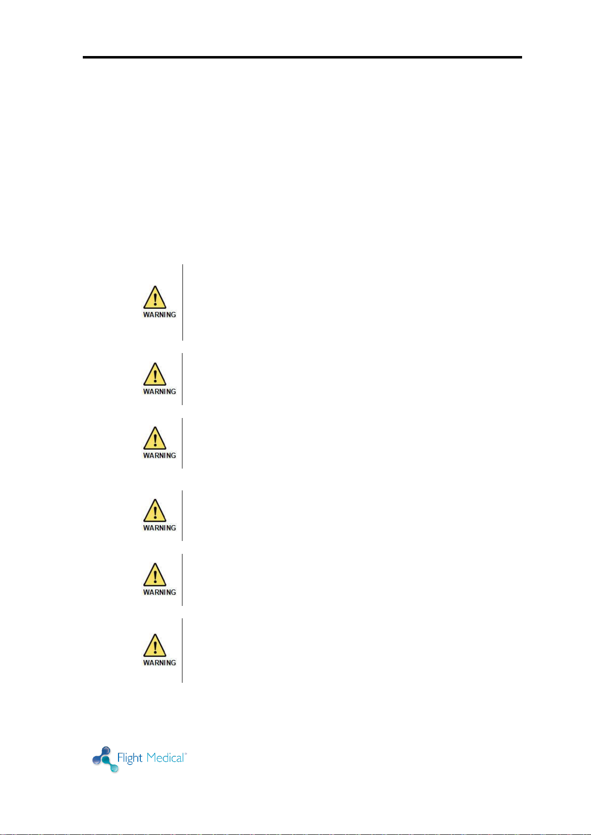
Safety Instructions
Operator's Manual | 2-1
External power connection: To maintain grounding
integrity when using AC power, only connect to hospital
grade receptacles. Always disconnect the external power
supply prior to servicing. There is a risk of explosion if
used in the presence of flammable anesthetics.
All settings and adjustments in the different ventilation
modes must be made in accordance with a physician's
prescribed therapy.
Do not use electrically conductive patient circuits.
Always use a clean, disinfected patient circuit.
Always use an outlet filter or equivalent at the Airway
Pressure Connector, to protect the internal transducers
from moisture and other contaminants.
Always use appropriate monitors to ensure sufficient
oxygenation and ventilation (such as pulse oximeter
and/or capnograph) when the FLIGHT 60 Ventilator is in
use on a patient.
2 Safety Instructions
At all times, strictly follow this manual. The safe use of the FLIGHT 60
Ventilator requires full understanding of its operation, and adherence to the
manual's instructions. The equipment is only to be used for the purpose
specified in Section 1.1. Observe all of the WARNINGS and CAUTIONS posted
in this manual, and on buttons found on the FLIGHT 60 Ventilator and
associated accessories.
2.1 General Warnings
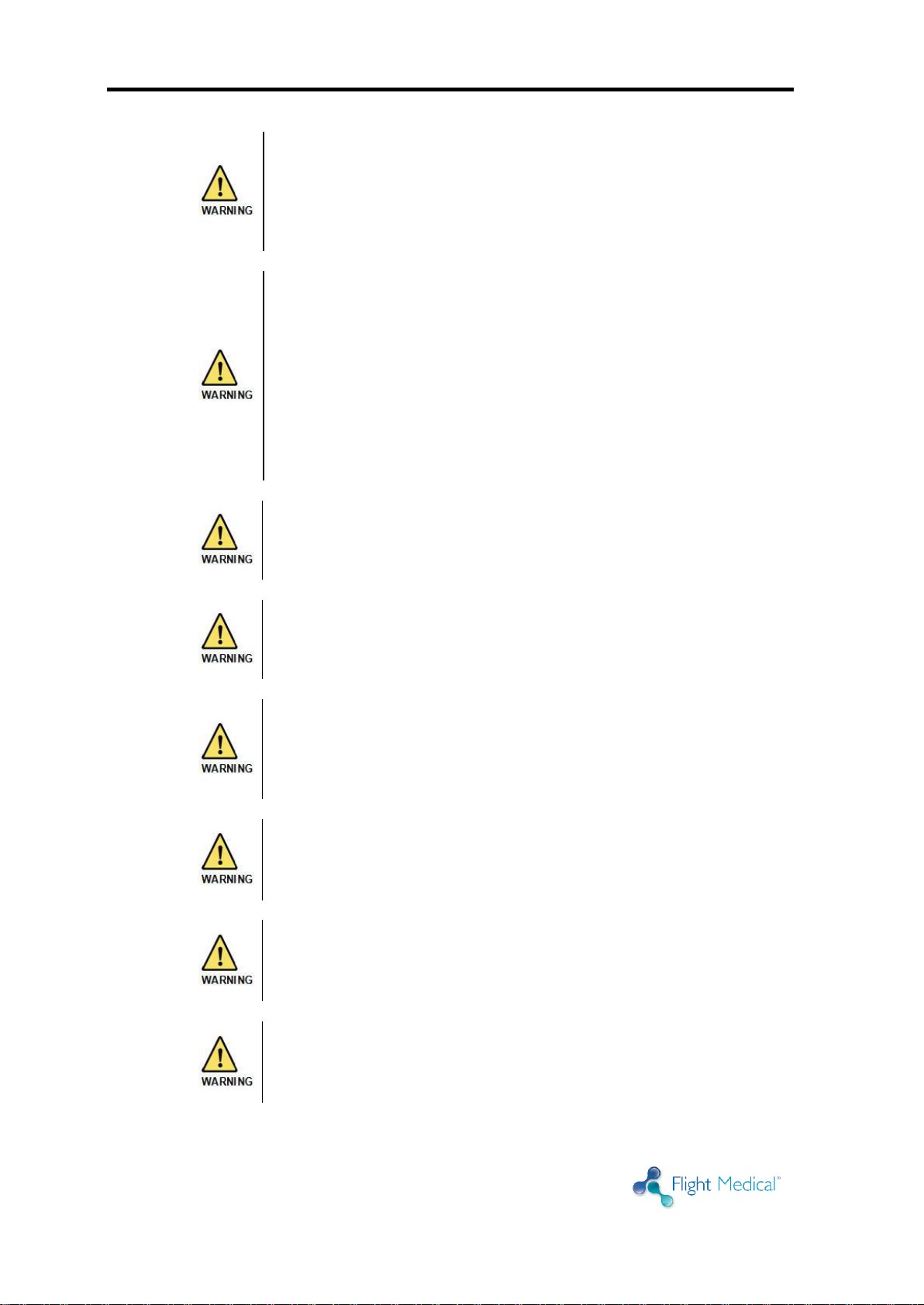
Safety Instructions
2-2 | Flight 60
If a fault is detected in the ventilator and its life support
functions are in doubt, immediately discontinue use; use
an alternative method of ventilation until the fault has
been corrected, and contact your provider or FLIGHT
MEDICAL immediately.
The ventilator is ready for operation only when:
It is completely assembled.
The Quick Check Procedure, including the
Exhalation Valve Calibration has been
successfully completed.
Constant attention by qualified medical personnel is
recommended whenever a patient is ventilated with the
FLIGHT 60 Ventilator.
Failure to identify and correct alarm violations may result
in patient injury.
Ensure that the oxygen source is not empty before and
during the use of the optional Oxygen Blending Bag Kit.
As Li-Ion batteries are charged and discharged over time,
their ability to hold a charge is decreased with use. This
can shorten the length of time the ventilator can function
while on battery power.
The batteries should be replaced when the batteries no
longer meet the needs of the user. This depends on a
number of factors including settings and usage patterns.
When the FLIGHT 60 Ventilator is used for transport
applications, ensure that the internal batteries are fully
charged prior to use.
When the Battery Empty alarm sounds, only a limited
amount of battery power remains, and an alternate power
source should be found immediately.
Safety Instructions
Operator's Manual | 2-3
Charge the batteries for a minimum of three hours before
powering the ventilator from the batteries. This provides
fully charged batteries.
During storage, charge the batteries for a minimum of
three hours every 30 days. This provides charged
batteries.
Always ensure that the green Ext. Power LED is
illuminated after connecting the FLIGHT 60 Ventilator to
an external AC or DC power source. If the LED is not
illuminated, check all power connections and resolve any
problems.
Always plug the FLIGHT 60 Ventilator into an AC power
supply source when not in use, to ensure best battery
performance.
The flow resistance of the air inlet filter, located on the
right side of the ventilator, is likely to increase with
repeated use. Ensure that the filter is changed regularly.
Only a FLIGHT MEDICAL approved patient circuit can be
used with the FLIGHT 60 Ventilator.
For pediatric ventilation ensure that the patient circuit
type is suitable for pediatrics ventilation. The Flight 60
Flow Sensor's dead-space is 19cc; consider using a Flow
Sensor Pediatric Adaptor to reduce dead-space when
ventilating pediatric patients.
Only a FLIGHT MEDICAL approved exhalation valve can be
used with the FLIGHT 60 Ventilator
Perform an exhalation valve calibration each time a
circuit/exhalation valve is installed.
Safety Instructions
2-4 | Flight 60
To avoid the risk of cross contamination, the disposable
patient circuit and exhalation valve (single use), must be
discarded in a responsible manner. The user should not
clean, disinfect or sterilize the circuit or the exhalation
valve element for reuse.
MR unsafe – keep away from magnetic resonance
imaging (MRI) equipment.
Only use medical grade oxygen with the high and low
pressure ports.
Do not place liquid containers in the immediate vicinity or
on top of the FLIGHT 60 Ventilator. Liquids that get into
the ventilator can cause equipment malfunction and
damage.
An authorized FLIGHT MEDICAL factory-trained technician
must do all service or repairs performed on the FLIGHT 60
Ventilator.
Do not open the ventilator or perform service on an open
unit while connected to external power.
Use standard antistatic techniques while working inside
the ventilator or handling any electronic parts.
Clean all external parts of the ventilator prior to servicing.
2.2 Cautions
Safety Instructions
Operator's Manual | 2-5
Water in the oxygen supply can cause equipment
malfunction and damage.
Batteries contain Li-Ion. Do not discard them in an
incinerator or force them open. Batteries should not be
disposed of with normal waste.
Review FLIGHT 60 Ventilator Operator’s Manual before
servicing the ventilator.
Use the tools and equipment specified in this manual to
perform specific procedures.

Ventilator Description
Operator's Manual | 3-1
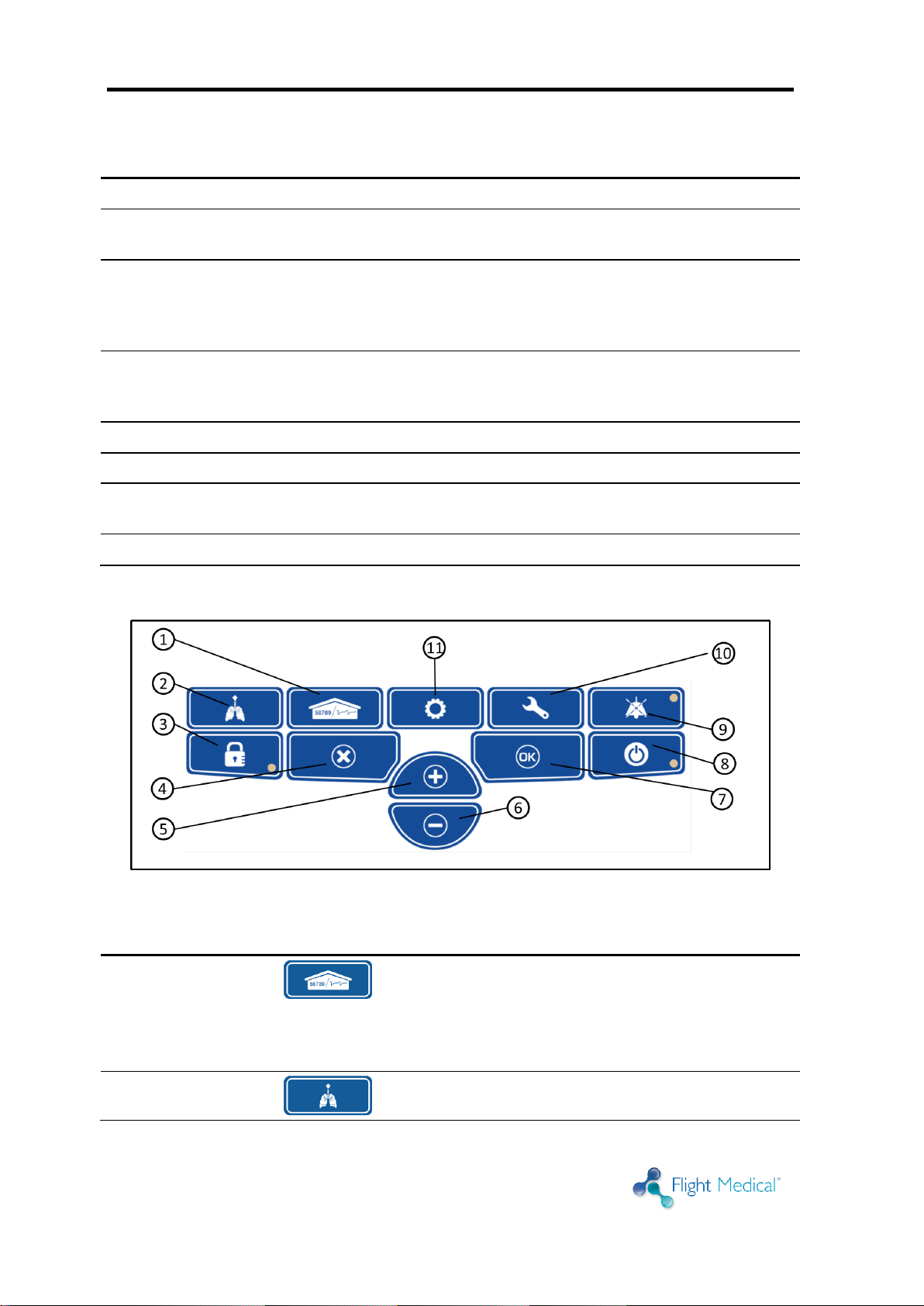
Label
Name
Description
1
Patient Circuit Connector
Composed of a gas outlet and quick connector.
2
+/- button
Enables the user to adjust setting parameters.
3
Panel Lock button
Enables the user to lock the ventilator’s control, preventing
accidental changes. Pressing the button of a locked panel and
then Enter, unlocks the panel.
4
On/Off button
Turns the ventilator on or off, to start or stop ventilation.
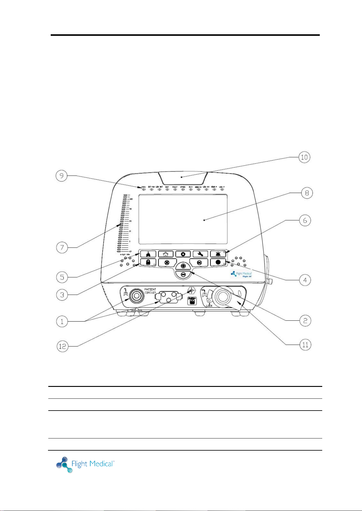
3 Ventilator Description
3.1 Front Panel Features
The front panel contains the control buttons, visual indicators, display screen,
and patient circuit connection.
Figure 1 – Front Panel
Ventilator Description
3-2 | Flight 60
Label
Name
Description
5
Manual Breath button
Delivers a user initiated manual inflation.
6
Audio Paused / Alarm Reset
button
Toggle button. Pressing Audio Paused temporarily silences the
audible alarm; pressing Alarm Reset clears lit alarm LEDs.
7
Pressure Gauge
The pressure gauge is a visual indicator of breath activity. The
gauge displays the airway pressure in the patient circuit at all
times. LED intensity can be controlled through the service
screen.
8
Display touch screen
Enables the user to modify the ventilation, alarm, and
technical settings, and to view real time patient data, alarms,
battery status and logs.
9
LED Indicators
Inform the user of various events (see Section 3.1.1).
10
Primary Alarm LED
Flashes red to indicate that there is a high priority alarm.
11
Dual Limb Exhalation Valve
(Optional)
Connects the patient circuit expiratory limb.
12
Nebulizer Port (optional)
Connects the pneumatic nebulizer.
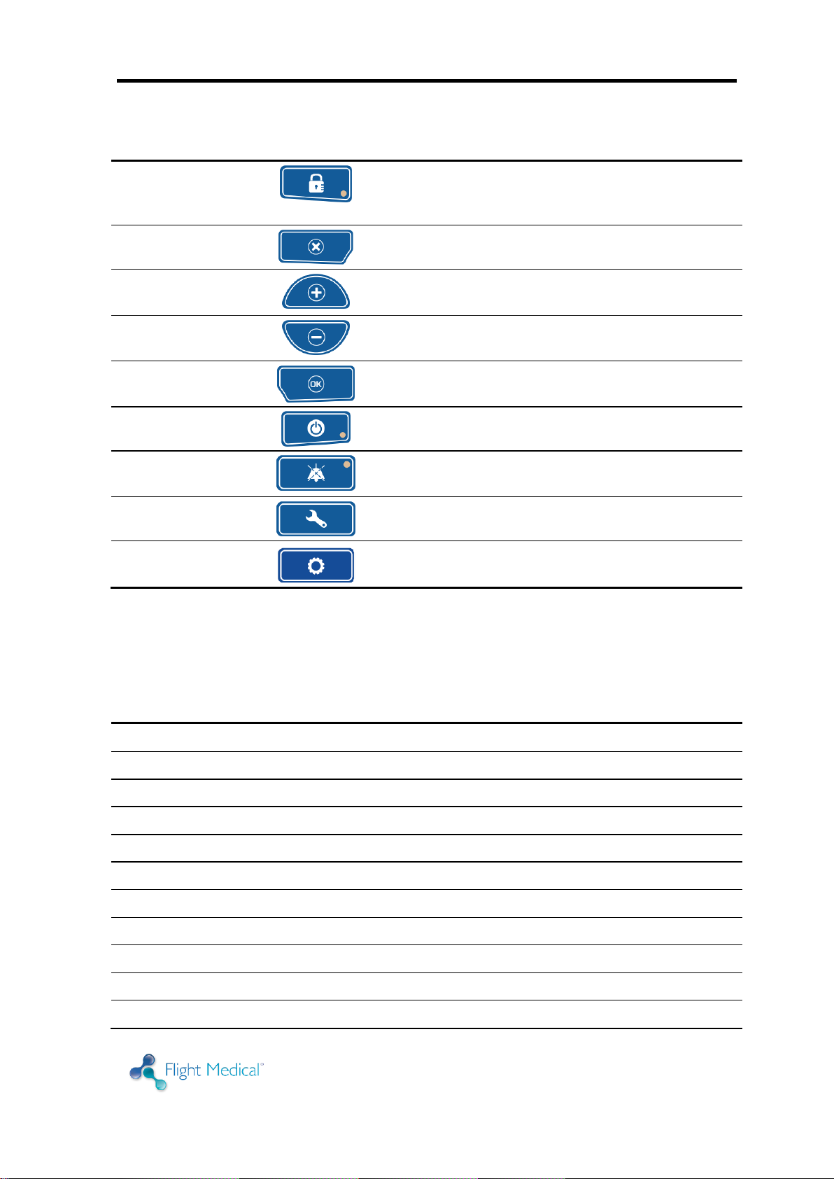
Item
Symbol
Description
1 – Parameters
(home)
The Parameters screen is the Flight 60's default screen.
Display switches automatically to Parameters from the
other screens if not operated for 30 seconds.
Use the Parameters button to toggle between the numeric
and the graphic displays.
2 - Manual Breath
Delivers a user initiated manual inflation.
3.1.1 Control Buttons
Figure 2 – Control Buttons
Ventilator Description
Operator's Manual | 3-3
Item
Symbol
Description
3 – Panel Lock
Enables the user to lock the ventilator’s control, preventing
accidental changes. Pressing the button of a locked panel
and then Enter, unlocks the panel.
4 – Cancel
Enable the user to cancel parameters change.
5 – Increase
Button
Enables the user to adjust setting parameters upwards.
6 – Decrease
Button
Enables the user to adjust setting parameters downwards.
7 – OK (Enter)
Enable the user to confirm parameters or mode change.
8 – On/Off
Turns the ventilator on or off, to start or stop ventilation.
9 – Alarm Reset
The Alarm Reset silences the audible alarm and clears lit
alarm LEDs.
10 – Technical
Technical data and selection options.
11 – Extended
Additional ventilation parameters screen.
LED Indicator
Description
TRIG
Green LED indicates a patient’s breathing effort.
EXT PWR
Green LED indicates that an external power source is being applied to the ventilator.
LOW BAT
Red LED indicates that total batteries charge level has dropped below 30%.
BAT
Orange LED indicates that the ventilator is powered on batteries.
FAULT
Red LED indicates a ventilator malfunction.
APNEA
Red LED indicates that the apnea alarm limit is being violated.
BUV
Red LED indicates that backup ventilation is active.
HIGH MV
Red LED indicates that the high minute volume alarm limit is being violated.
LOW MV
Red LED indicates that the low minute volume alarm limit is being violated.
HIGH P
Red LED indicates that the high peak airway pressure alarm limit is being violated.
LOW P
Red LED indicates that the low airway pressure alarm limit is being violated.
3.1.2 LED Indicators
The LED indicators on the front panel inform the user of various events. The
following table describes the available LED indicators.
Ventilator Description
3-4 | Flight 60
To ensure proper grounding and prevent possible shock
hazards, this device should only be connected to
grounded power receptacles.
HOME CAREGIVERS: External power in the home
environment must support min. 100 to max. 240 V AC,
and must have a grounded receptacle.
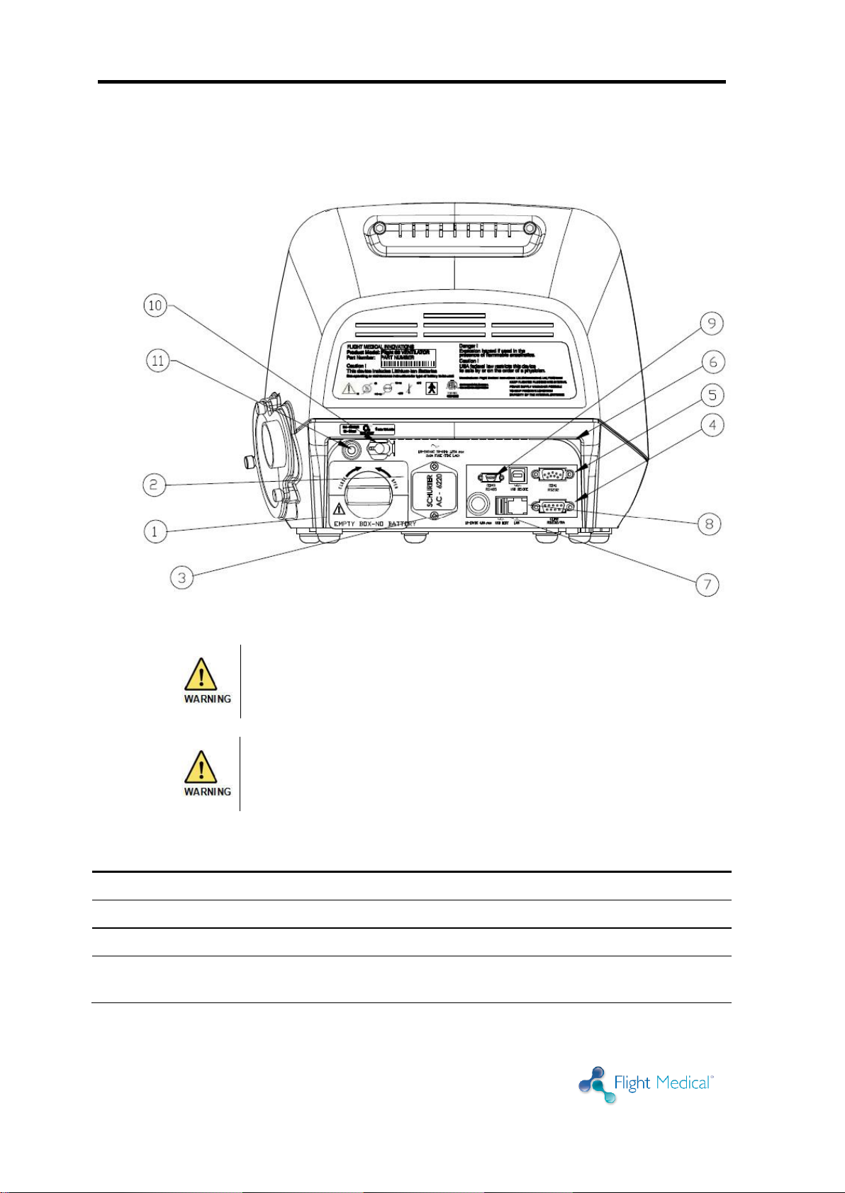
Label
Name
Description
1
Detachable Battery
Li-Ion 14.8 VDC
2
AC Connector with Fuses
100 – 240 V AC, 50 – 60 Hz, Fuse 8A (time lag)
3
DC Connector
12 – 15 V DC
4
RS-232 Serial Port (COM2)
Remote alarm connector (Normally Open and Normally Closed
options).
3.2 Back Panel Features
Figure 3 – Back Panel
Ventilator Description
Operator's Manual | 3-5
Label
Name
Description
5
RS-232 Serial Port (COM1)
Online output of events and error messages to the PC, using a
dedicated PCS2 protocol; for authorized and qualified service
technicians only.
6
USB B type
PC connector: USB port for downloading the main application
from the PC using a dedicated PCS2 protocol; for authorized
and qualified service technicians only.
7
USB A type
USB port for uploading LOG files to an external memory stick;
for authorized and qualified service technicians only.
8
LAN (RJ45)
LAN for network logging (currently not available).
9
Mini RS-485 (COM3)
For connecting FLIGHT MEDICAL peripherals. For future use.
10
Low Flow Oxygen Port
Low flow oxygen enrichment source.
11
High Pressure O2 Port
(optional)
Connects the high pressure O2.
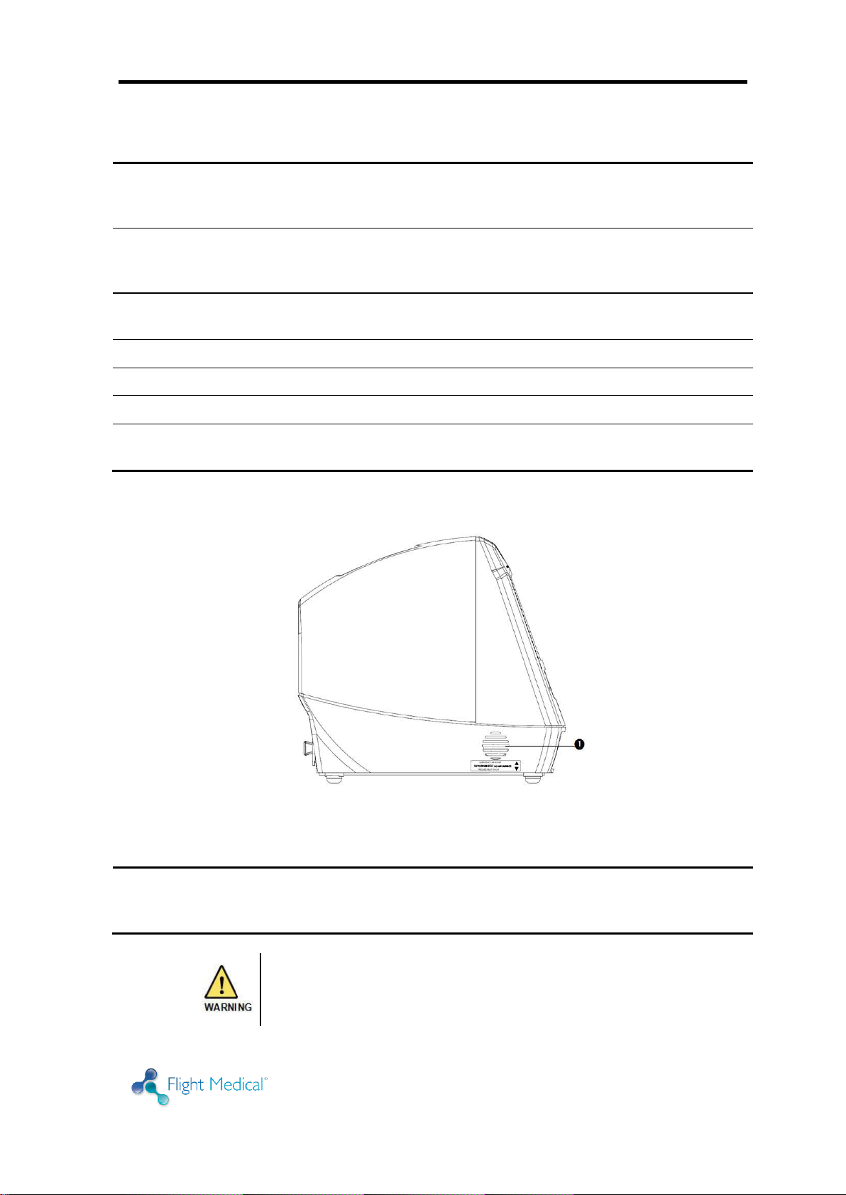
Label
Name
Description
1
Emergency Air Intake
Enables the patient to pull ambient air into the patient circuit in
the event of a complete system failure. The Air Intake opening
pressure is approximately -3 cmH2O (-3 mbar).
Do not obstruct the Emergency Air Intake! Any
impediment can result in patient suffocation.
3.3 Left Side Panel Features
Figure 4 – Left Side Panel
Ventilator Description
3-6 | Flight 60
HOME CAREGIVERS: Should a complete failure of the
ventilator occur, the Emergency Air Intake allows the
patient to breathe from room air through the intake valve.
Blockage of the valve can result in suffocation.
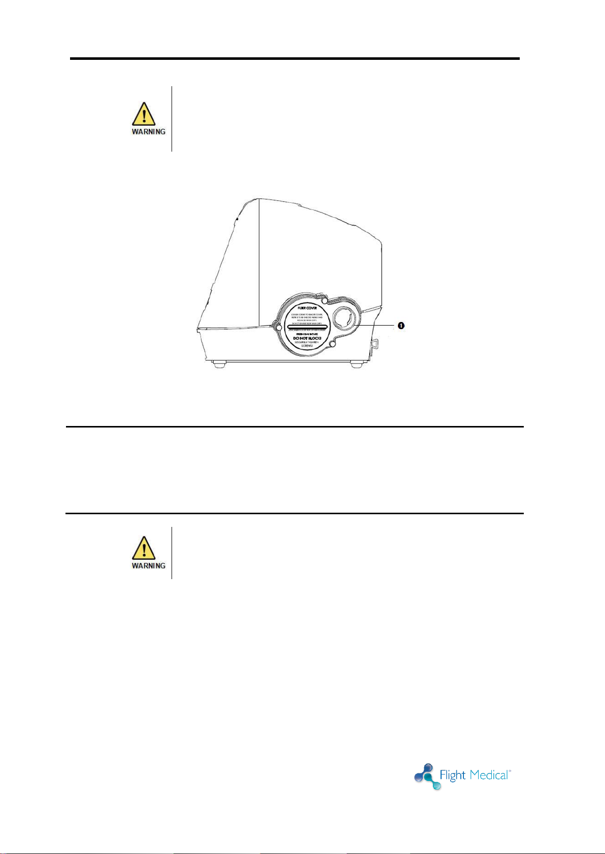
Label
Name
Description
1
Fresh Gas Intake and
Filter Cover
Environmental air enters through this 30 mm ID Fresh Gas Intake.
The air inlet particle filter is placed behind the Filter Cover to
protect the patient as well as the ventilator’s piston system from
dirt and particles. The Fresh Gas Intake also serves as the
attachment socket for the optional FLIGHT 60 Ventilator Oxygen
Blending Bag.
Do not block the Fresh Gas Intake.
3.4 Right Side Panel Features
Figure 5 – Right Side Panel

Installation
Operator's Manual | 4-1
Only properly trained personnel should install the
ventilator.
4 Installation
4.1 Introduction
Familiarize yourself with the instructions in this section prior to installing the
ventilator. Following all of the listed steps is essential for ensuring the safest
possible operation of the ventilator. Use the information in this section in
conjunction with established hospital protocols and homecare dealer
instructions.
4.2 Removing the Ventilator Parts from the Box
Before installing the ventilator, familiarize yourself with the various
components. Remove all of the items from the shipping box and inspect each
part and component for completeness and verify that there is no shipping
damage..
The complete assembly consists of the following parts:
FLIGHT 60 Ventilator
Operator's Manual
AC Power Cord
Patient Circuit – Single Patient Use
Air Inlet Filter (pk. Of five filters)
Detachable Battery (Main)
Integral Battery (Secondary)
4.3 Mounting the Ventilator
To mount the ventilator:
1. Mount the ventilator on a stable surface (e.g., bedside table or the Roll
Stand Assembly).
2. To mount the ventilator on the Roll Stand Assembly, follow the instructions
provided with the assembly; position the ventilator on a pedestal mount
and then secure it using the screws provided.

Basic Operation
4-2 | Flight 60
4.4 Installing the Detachable and Integral
Batteries
To install the detachable battery:
1. Insert the detachable battery into the ventilator.
2. Turn the lock dial clockwise, in the direction of the CLOSE arrow, until it is
firmly locked.
Figure 6 – Installing the Detachable Battery
To install the integral battery:
1. Insert the integral battery into the ventilator (bottom panel).
2. Attached the plastic integral battery cover and tightened the 4 screws with
a Philips screw driver.
4.5 Plugging in the Power Cord (for AC)
To plug in the power cord:
1. Plug the AC power cord into the power entry connector.
2. Plug the ventilator's electric cord into a properly grounded outlet.
The ventilator is now in STANDBY mode. The EXT PWR LED is illuminated,
and the batteries begin recharging.
Figure 7 – Plugging in the Power Cord
Installation
Operator's Manual | 4-3
Single limb patient circuit can be attached to both single and
dual ventilators
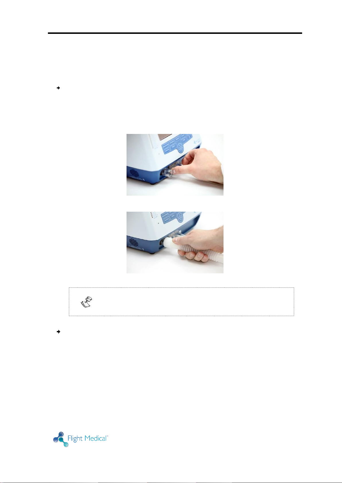
4.6 Attaching the Patient Circuit
The following procedure describes how to attach a patient circuit to the
ventilator.
To attach the single limb patient circuit:
1. Attach the quick connector to its socket on the front panel and tightly
secure.
2. Attach the 22 mm ID patient circuit to the Gas Output on the front panel.
3. If using with an HME, attach the HME to the flow orifice.
Figure 8 – Patient Circuit (Quick Connector)
Figure 9 – Patient Circuit (22 mm Tube)
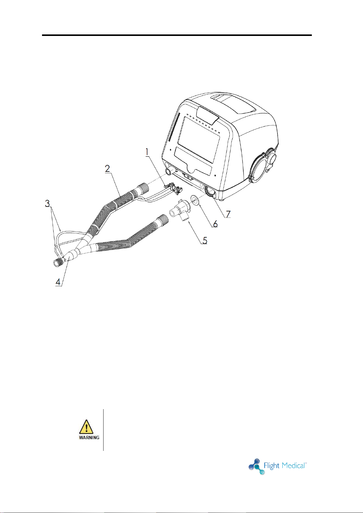
To attach the dual limb patient circuit:
1. Attach the quick connector to its socket on the front panel and tightly
secure.
2. Attach the 22 mm ID inspiratory limb to the Gas Output on the front panel.
3. If using with an HME, attach the HME to the flow orifice.
4. Place the exhalation valve diaphragm inside the exhalation valve base with
its holding tip facing forward.
5. Press the exhalation valve cover to its base. Rotate the exhalation valve
cover 1/4 turn clockwise to secure it into place. Verify the secure pin in
place.
Basic Operation
4-4 | Flight 60
Some disposable patient circuit/exhalation valve assemblies
are not compatible with the FLIGHT 60 Ventilator due to the
requirements of the ventilator's pressure management
system. If your disposable circuit fails consistently, switch to
a FLIGHT MEDICAL approved patient circuit to ensure that
6. Attach the 22 mm ID expiratory limb to the exhalation valve on the front
panel.
7. To detach the exhalation valve cover, press the pin and rotate the
exhalation valve cover 1/4 turn counter clockwise.
1. Quick Connector
2. Inspiratory Limb
3. Flow Transducer Lines
4. Flow Orifice
5. Exhalation Valve Cover
6. Exhalation Valve Diaphragm
7. Exhalation Valve Base
4.7 Circuit Test
Figure 10 – Dual Limb Patient Circuit
 Loading...