

Page 1
EN
1~11
中
12~22
Page 2
Brief History
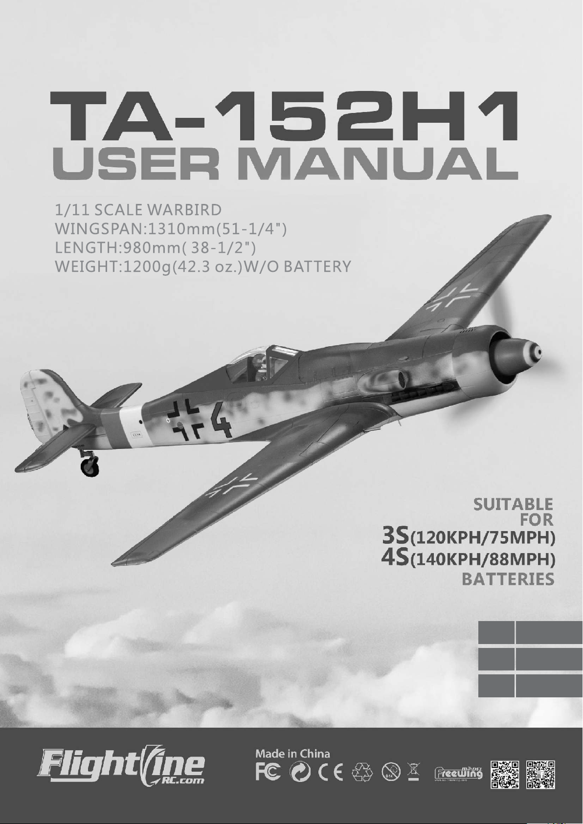
The Ta-152H1 is a high speed piston fighter developed from the Fw-190 near the end of World War II in Nazi Germany. Compared
with the Fw-190D which was a "quick fix", the Ta-152 was the ultimate "solution" however, due to the late development period, the
production quantity was too small to affect the war's outcome. In spite of this, it's excellent performance, still won the praise of both
sides of the war The Ta-152H1, along with the P-51D and the Spitfire XIV, were known as the ultimate piston fighters, their flight
performances being close to the limit of a piston engine fighter.
Overview
An 1/11 scale gives the Ta- 152H1 a 980mm length and a wingspan of 1310mm Its shape and contour lines are scaled down
from the actual aircraft and scale details and exquisite paint made it extremely realistic in appearance. Extensive use of plastic parts,
allow for quick and easy installation of the main wing, horizontal and vertical tail surfaces and we have utilized carbon fiber rods in the
main wing, horizontal tail and every control surface, to avoid distortions during high speed flight, making the airplane extremely stable.
Plastic hinges included with the kit allow you to further increase the reliability of the control surfaces. Inside the fuselage, we have
designed a ventilation system, allowing the ESC to be effectively cooled thereby prolonging its life. The battery tray is mounted with
screws,and divided into two levels,making it easy to install the ESC and a non- slip mat effectively prevents the battery from moving.
The Ta-152H1 uses a high power 3648- 830KV brushless motor with a 10x6 3- blade scale propeller, a light fuselage (1200 gm
without the motor) with a large battery compartment which can accommodate 3S/4S batteries for flight. When using a 3S battery, it can
reach speeds up to 120kph/75mph. when using 4S battery, it can reach speeds up to 140kph/ 88mph. Also available is a special 2- blade
high speed power system set( which includes a 2- blade 12x8 propeller, spinner and back plate along with a 3648 880 kv motor).
Using this modification, the Ta-152H1 can reach top speeds of up to 160kph/100mph!
Flight features
The FlightLineRC Ta-152H1, with its long wingspan, has excellent flight stability and a small turning radius. The smaller body
combined with it's high power give it excellent speed and climb performance. The wide main landing gear (350 mm)
propeller torque at take off, making it easier to maintain directional control during take off. With the stock power setup utilizing 3S/4S
batteries, it has a
will correct this and help make for a slow and gentle landing.
Color scheme introduction
This airplane has a factory applied paint scheme as well a a variety of decals to chose from as well as placement instructions, so
you can customize your airplane to suit your taste.
18M/15M take-off run. When landing with flaps, there will be a slight nose down tendency, a slight flap/up elevator mix,
, helps offset the
1. This is not a toy! Operators should have some basic experience. Beginners should operate only under the guidance of a professional
instructor.
2. Before beginning assembly, please read through the instructions and carefully follow them through the build.
3. Freewing and it's vendors will not be held responsible for any losses due to improper assembly and operation.
4. Model airplane operators must be at least 14 years of age.
5. This airplane is made of EPO foam material, covered with surface spray paint. Don't use chemicals to clean as it may cause damage.
6. You should avoid flying in areas such as public places, areas with high voltage power lines, nearby highways or airports or an other
areas where laws and regulations clearly prohibit flight.
7. Do not fly in bad weather conditions, including thunderstorms, snow, etc.
8. Lipo batteries should be properly stored in a fire safe container and be kept at a minimum of 2M distance away from flammable or
explosive materials.
9. Damaged or scrap batteries must be properly discharged before disposal or recycling to avoid spontaneous combustion or fire.
10. At the Flying Field, properly dispose of any waste you have created. Don't leave or burn your waste.
11. Make sure your radio is powered up and the throttle is in low position before connecting the Lipo Battery.
Index
Build Notes
Product Basic Information, Package List 2
Assembly:
Fuselage and Main Wing 3
Elevator Assembly 4
Installing Elevator/Rudder Pushrods Guns
Pitot Tube, Antennae and Boarding Step 5
Servo Introduction/Installation 5
Main Wing Servo Installation 6
Elevator/Rudder Servo Installation 6
Pushrod Instructions 6
Main Landing Gear Assembly 7
Tail Gear Installation 7
Center of Gravity 7
Battery Installation 8
Control Board Use Introduction 8
Motor Parameters 8
Power Systems 9
ESC Installation 9
Control Direction Test 10
Dual Rates 10
Installing the Optional Plastic Hinges 11
1
1
TA-152H1
Item No.:FLW05
Page 3
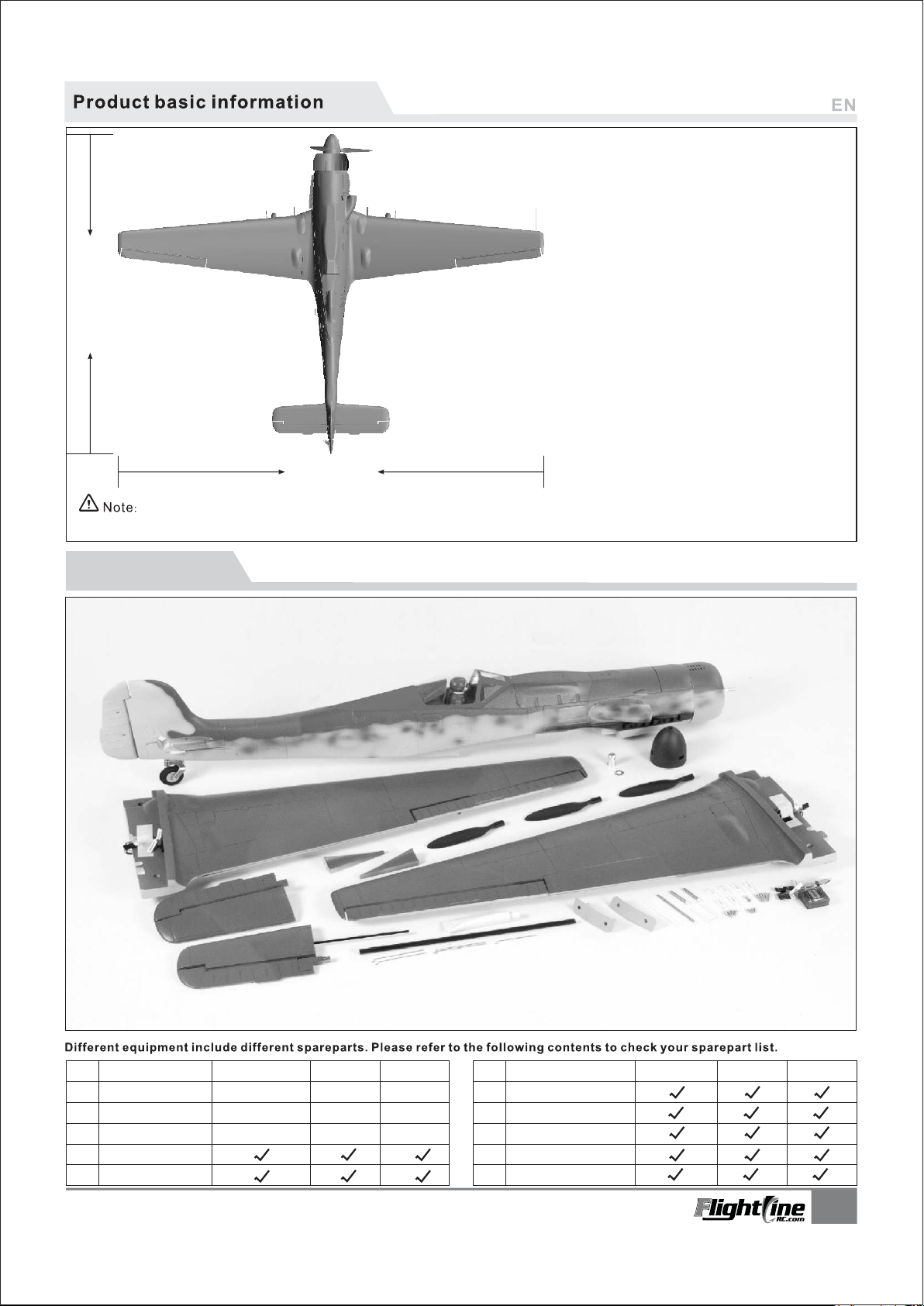
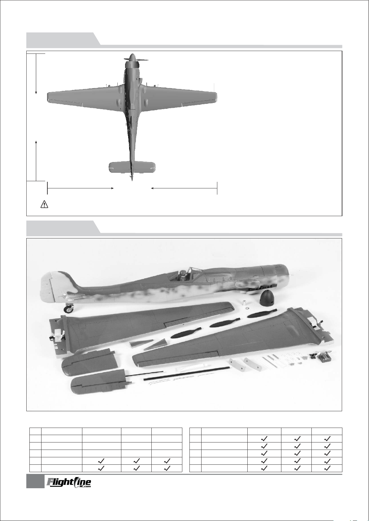
980mm(38.6")
1310mm
(51.2")
our accesso
cannot provide technical support if you have a problem.
The parameters stated here are derived from test results using
ries. If you use other accessories, the results will differ. We
Package list
Wing loading:88g/dm²
Motor:3648-830KV brushless motor
Propeller:3-blade 10×6
ESC: 60A brushless ESC
Servo:9g MG×2, 9g plastic×4
Weight: 1200g (w/o battery)
Aileron: Yes
Elevator: Yes
Rudder: Yes
Flap: Yes
Landing gear: Retract landing gear
Main landing gear cabin door
Material: EPO
High speed DIY spare-part
(The following is DIY spare-part list, please contact
your distributor to purchase separately.)
2-blade propeller spinner
2-blade propeller backing plate
3648-880KV brushless motor
2-blade 12×8 propeller
No.
Spareparts name
Fuselage
1
Main wing
2
Horizontal tail
3
Decals / Manual
4
Control board
5
TA-152H1
Item No.:FLW05
PNP
Pre-installed all
electronic parts
Pre-installed all
electronic parts
Pre-installed all
electronic parts
ARF Plus
Pre-installed
servo
Pre-installed
servo
Pre-installed
servo
ARF
No electronic
equipment
No electronic
equipment
No electronic
equipment
No.
Spareparts name
Propeller and parts
6
Spinner and parts
7
8
9
10
Carbon tube
Glue and Screws
Pushrod/Plastic parts
PNP
ARF Plus
ARF
2
Page 4
Assembly Instructions
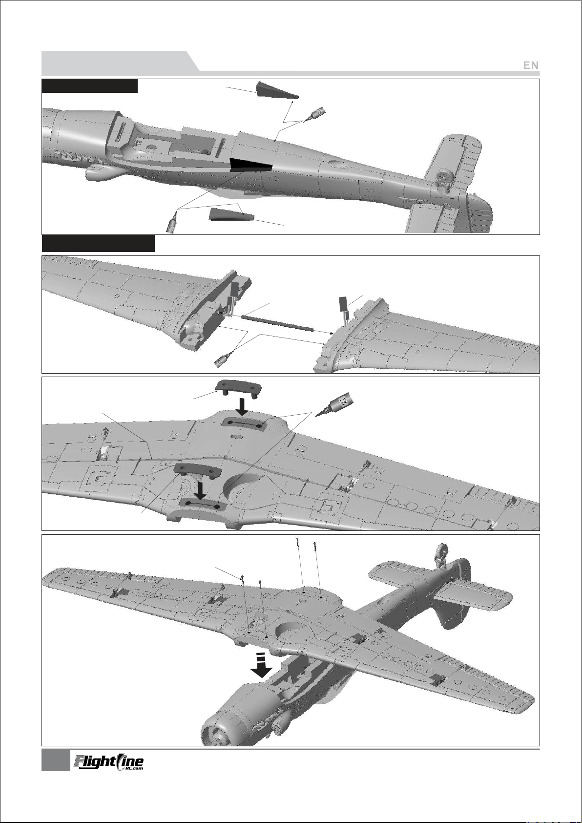
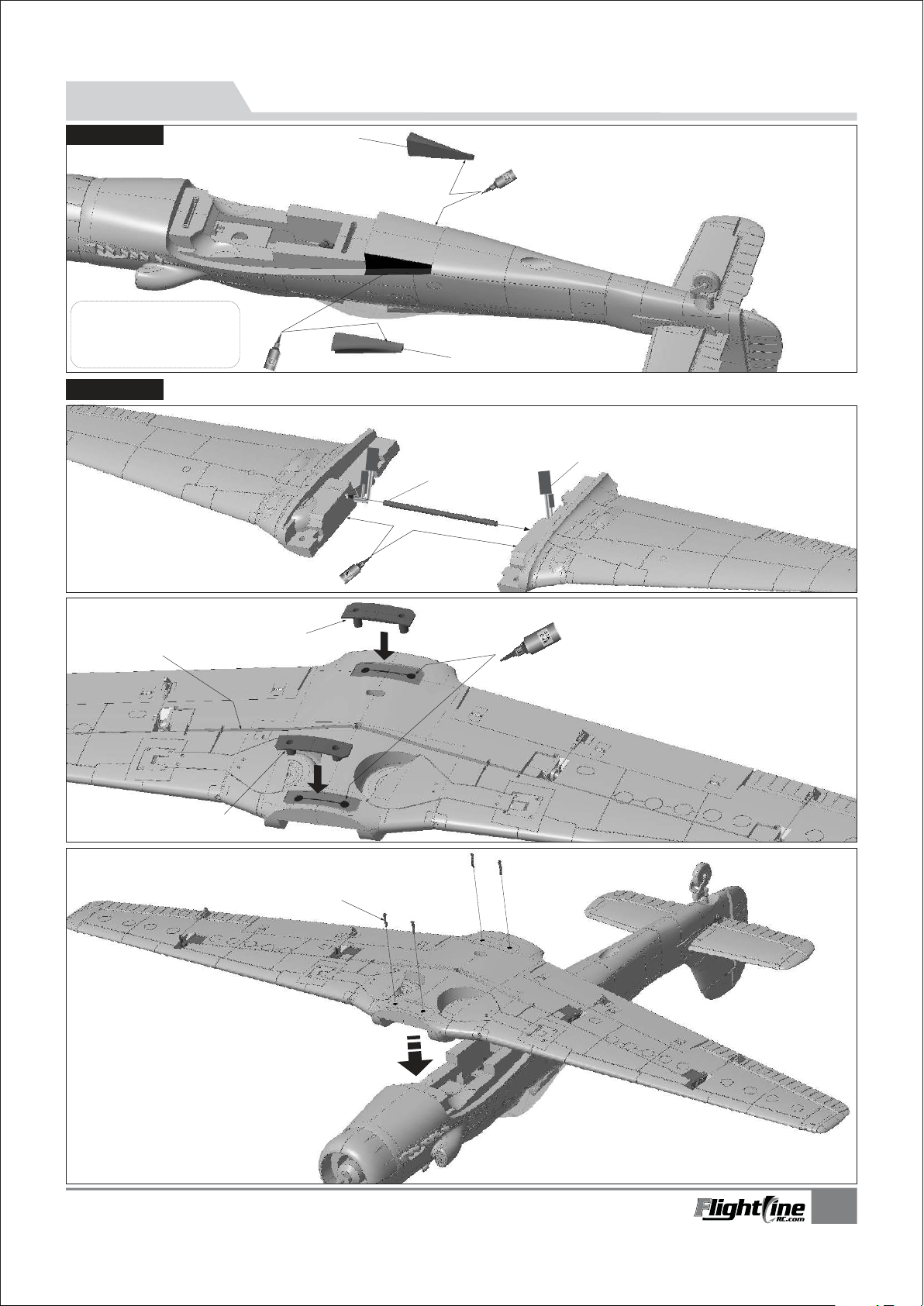
Fuselage Assembly
Note: EPO Glue is included with the
kit. For best results, spread evenly,
wait for 90 seconds, then attach,
pull apart and attach several times
let the glue get stringy
Install
ing the main wing
A-Carbon Fiber tube
(Ø8x200mm)
B-Servos wire
C
A
1.Before assembly, remove the battery hatch cover.
2.Use glue to attach the part A and B on the fuselage.
B
1.
Insert the carbon fiber tubes to main wing.
2.Use glue to attach the left/right main wing
which will help strengthen the wing.
A
B
2.Use the glue to attach the main wing
A
plastic attachment points, parts A and B
on the main wing.
B
(Pa3x12mm 4pcs)
Screw
3.Use 4 screws to fix the main wing.
3
TA-152H1
Item No.:FLW05
Page 5
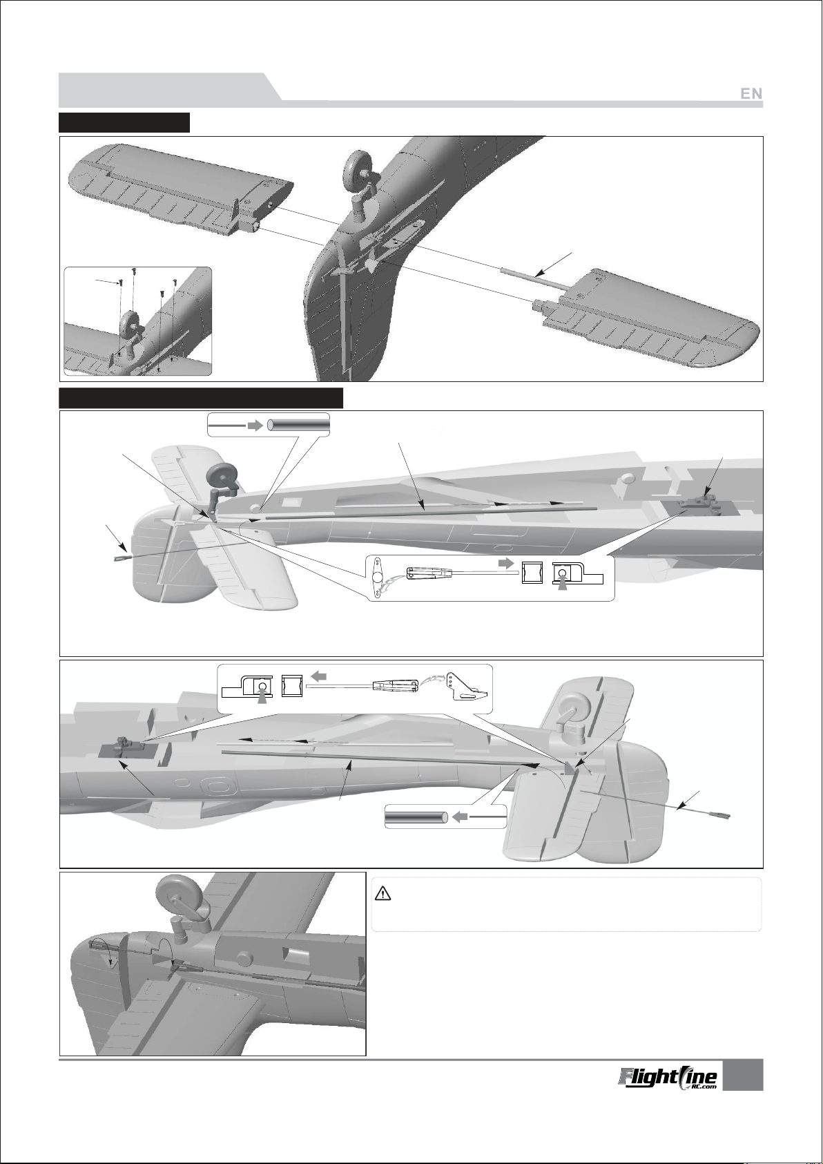
Assembly Instructions
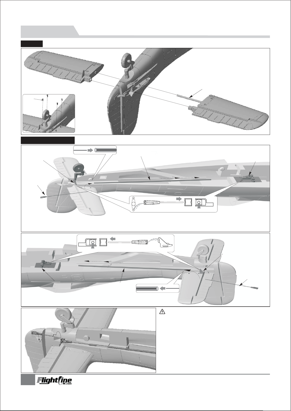
Elevator Assembly
1. Using the Carbon Fiber rod install the
left and right Horizontal Stabilizers
2.Turn the fuselage over and use the 4
provided screws to secure the elevator.
A-Carbon tube
B-Screw
B
(Ø4x200mm)
(KA2.3x8mm 4pcs)
Installing the elevator/rudder pushrods
D
A
1.Insert one side of rudder pushrod A ,through plastic tube B, to the servo arm C.
2.Snap the clevis of rudder pushrod to the tail gear steering arm D.
B
A
C
C
1.Insert one side of elevator pushrod A ,through plastic tube B, to
the servo arm C.
2.Snap the clevis of elevator pushrod to the elevator horn D.
B
Note: when installing the rudder pushrod, make sure the tail gear is
centered. Then attach the rudder pushrod, and adjust the plastic clevis to center
the rudder.
1.Use glue to attach the rudder horn to the rudder.(as the left
photo shown).
2.Use rudder pushrod to connect the tail gear steering arm
and rudder horn.
TA-152H1
Item No.:FLW05
D
A
4
Page 6
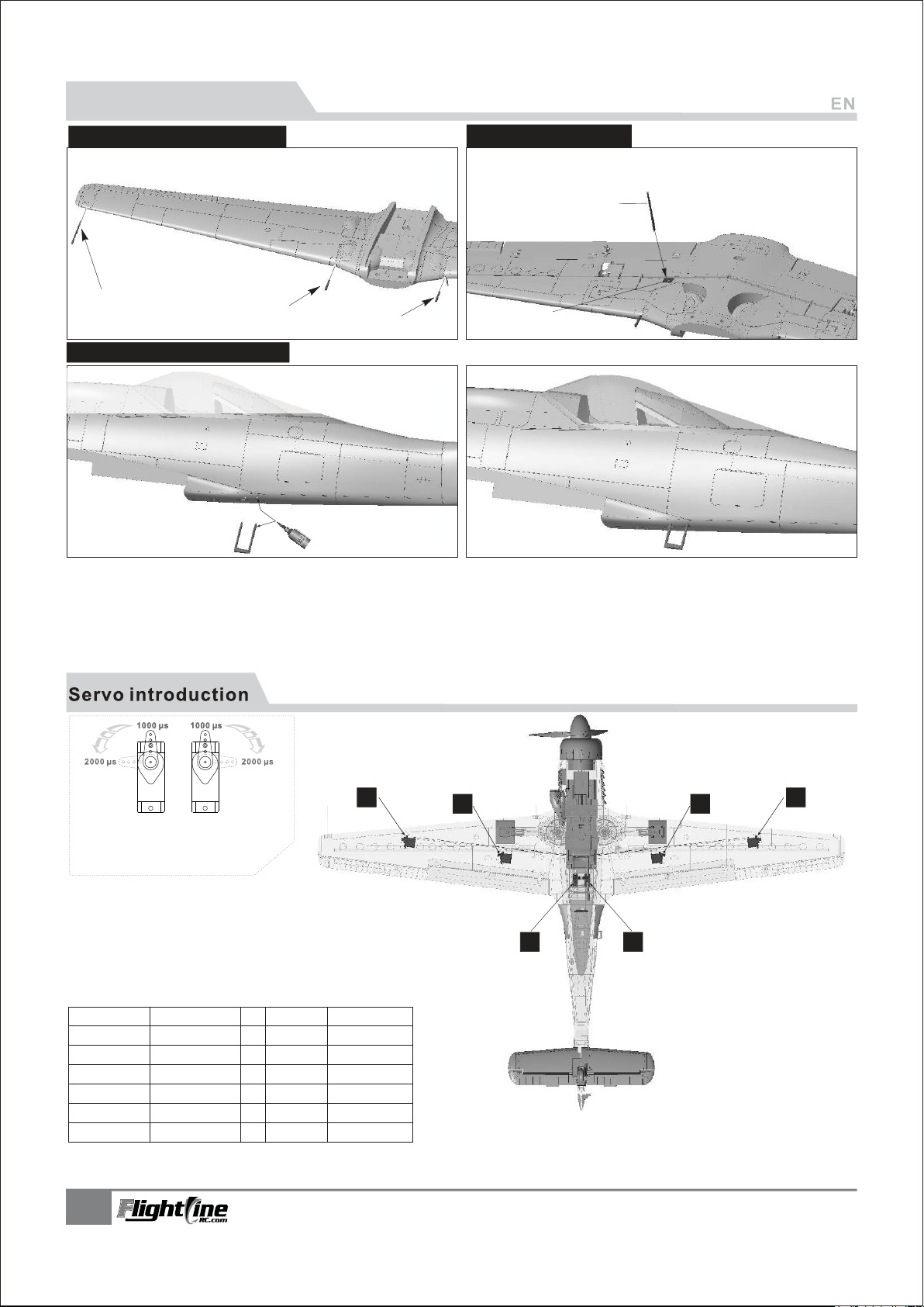
PNP Install instructions
Guns/pitot tube Assembly
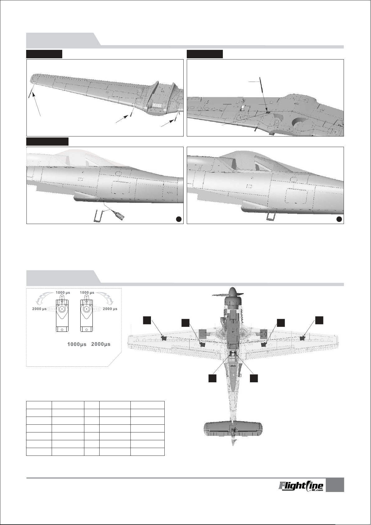
1.Insert the pitot tube A and gun B into the front of main wing.
Antenna Installation
2.Insert the antenna C to the antenna fixed mount in the
under surface of the main wing.
C
A
B
B
Antenna fixed mount
Boarding Step installation
3. Drill two small holes and use the glue to attach the
Boarding Step.
Note:
After finishing the above steps, depending on the type of control board, insert
aileron,flap servo cable and landing gear cable to the control board.
A servo or reversed servo is defined as
follows:
When the servo input signal changes
from 1000ųs to 2000ųs, The servo arm
rotates clockwise, its a positive servo. If
it rotates counter clockwise, its a
reversed servo.
If you need to purchase another brand servo, please refer
to the following list to choose correct size.
Position
Aileron(Left)
Aileron(Right)
Flap(Left )
Flap(Right)
Rudder
Elevator
Model
9g plastic
9g plastic
9g plastic
9g plastic
9g Digital MG
9g Digital MG
No.
1
2
3
4
5
6
Pos./Rev.
Positive
Positive
Reverse
Positive
Positive
Positive
Cable length
500mm
500mm
250mm
250mm
300mm
300mm
5
34
12
56
TA-152H1
Item No.:FLW05
Page 7
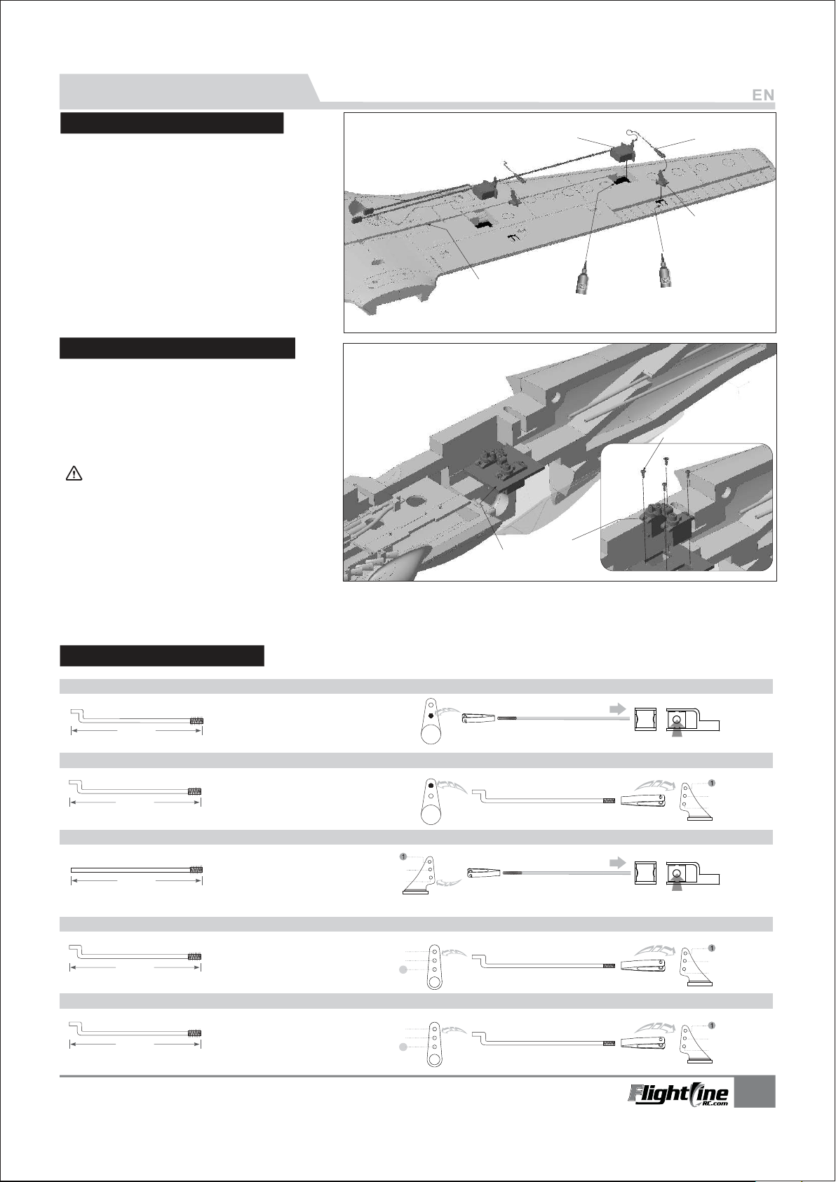
Servo Installation Introduction
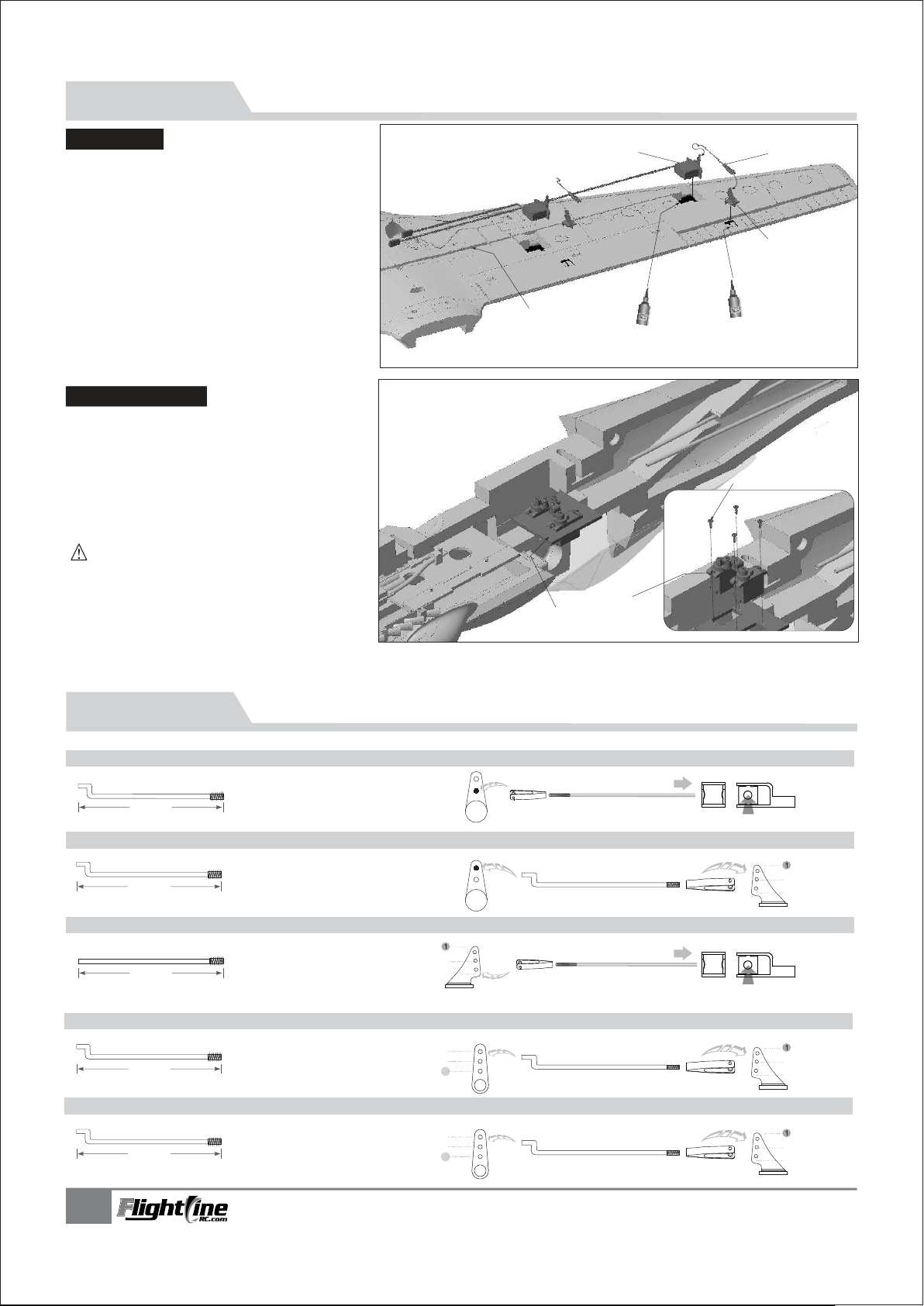
Main wing servo Installation
1.Use servo tester or radio to center the
servo.
2.Use glue to install the servo and aileron
horn on the main wing.
3.Feed the servo cable through the slot, after
installing all the servos, apply the decal
over the slot.
4. Insert the end of the control rod into the
servo arm, adjust its length. And snap the
clevis to the aileron horn.
5.Repeat the above four steps for other main
wing and flap servo.
Elevator/rudder Servo Installation
1.Use servo tester or radio to center the
servo.
2.Use screw A to secure the 9g servo onto
the wooden piece.
3.Slide the servo cable under the wooden
piece, and feed it through to the battery
compartment.
Note: If you choose not to use the factory servo,
the chosen servo may be larger. If that is the case, you
need to remove the fixed wooden piece and glue the
servo in the servo position in the fuselage
A - 9g servo
B - Main wing pushrod
C - Aileron horn
D - Main wing servo trough
D
A
B
C
PWA2x8mm
A
Pushrod instructions
Steering pushrod size
490mm
(19-1/4")
Rudder pushrod size
41.5mm
(1-5/8")
Elevator pushrod size
490mm
(19-1/4")
Aileron pushrod size
Pushrod diameter Ø1.2mm
Pushrod diameter Ø1.2mm
Pushrod diameter Ø1.2mm
C
B
Steering pushrod mounting hole
Rudder pushrod mounting hole
Elevator pushrod mounting hole
2
3
Aileron pushrod mounting hole
2
3
67.8mm
(3-1/8")
Flap pushrod size
41.5mm
(1-5/8")
TA-152H1
Item No.:FLW05
Pushrod diameter Ø1.2mm
Pushrod diameter Ø1.2mm
1
2
3
Flap pushrod mounting hole
1
2
3
2
3
2
3
6
Page 8
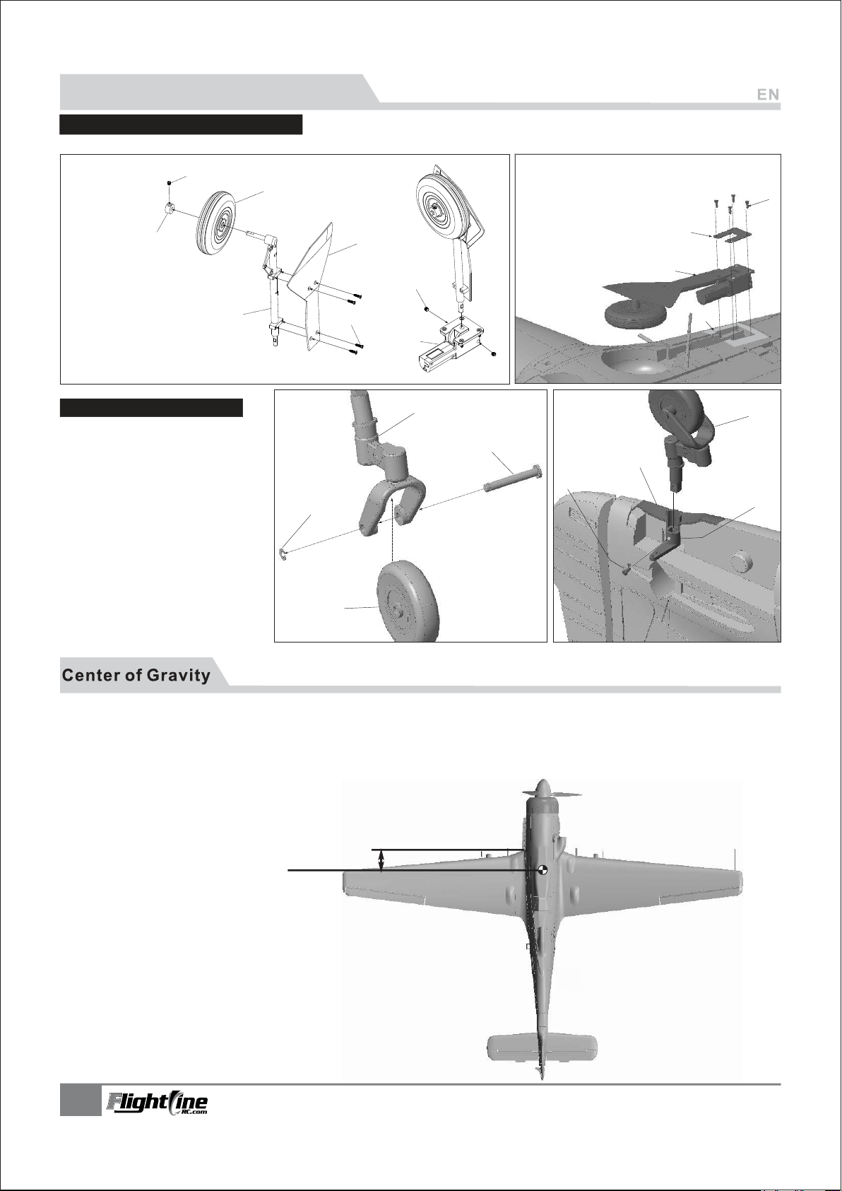
Landing gear assembly Instructions
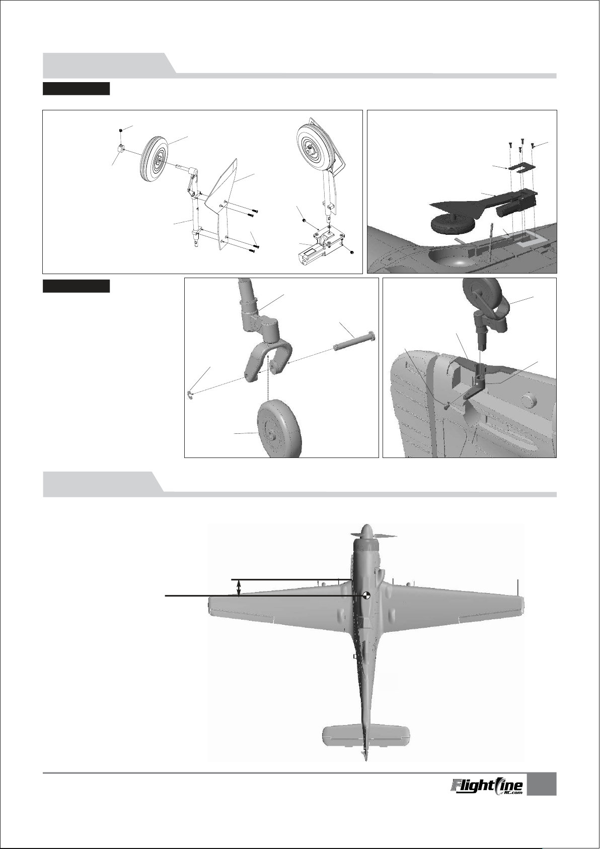
Main Landing Gear Assembly
Please assemble/ disassemble the main landing gear according to the diagram below
A
B
C
D
-
A
Main landing gear strut
-
B
Main wheel
-
C
Wheel locks
-
Jimi screw
D
-
E
Main gear cabin door
-
Screw
F
-
Retract servo
G
-
Screw
H
(M3×3mm)
D
C
(Ø65×16mm)
(Ø5.5×Ø4.2mm)
(M3×3mm)
(FA2×6mm)
B
E
H
A
F
G
-
Screw
(KA2.6×12mm)
-
Landing gear reinforcement plate
-
Main landing gear
-
Landing gear mount
C
A
B
D
Install the tail gear set
1.Refer to the right photo, install the tail
landing gear set.
2.Insert the tail gear set C to the fixed
plastic part B, and continue to insert to
the tail steering arm A.
3.Use screw D to fix the tail steering arm.
-
A
Rear wheel
-
B
Rear gear supporting rod
-
C
Rear wheel shaft
-
D
E-buckle
E - Tail steering arm
F - Rear gear fixed plastic part
G - Tail gear set
H - Screw
(Ø35×10mm)
(Ø5×Ø2mm)
(PA1.6×6mm)
D
A
A successful flight is directly related to a proper Center
of Gravity.
If you cannot acheive a proper CG by adjusting the
battery position, you can use an alternate material
such as a sticky backed weight to achieve the
optimum CG
B
C
F
H
G
E
72mm
(2-13/16")
7
TA-152H1
Item No.:FLW05
Page 9
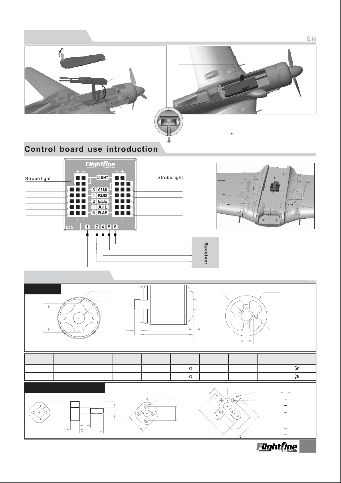
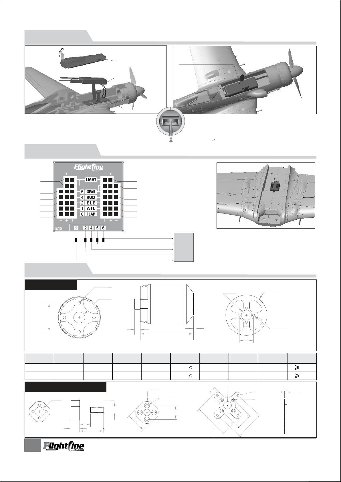
Battery Installation
Lift up on the tape to remove the Battery
compartment hatch
Battery
Install in the battery hatch and use the
velcro strap to secure it.
Velcro
Before connecting the battery to the ESC , please
power up the transmitter and make sure the throttle
stick is in the lowest position.
Landing Gear
Rudder/Nose steering
Elevator
Aileron
Flap
Dan's Note: The control board may
not have all the outputs as shown
in the diagram. If not, plug the
existing outputs into the receiver
and route the other servos directly
to the receiver.
Battery tray
Rudder/Nose steering
(power to the receiver)
Landing Gear
Elevator
Aileron
Flap
Landing gear
Rudder
Elevator
Aileron
Battery Hatch Size:200×65×40mm
The battery size range we recommend for this airplane:
3S 11.1V 2600mAh ~ 3S 11.1V 4000mAh 4S
14.8V 2600mAh ~ 4S 14.8V 4000mAh
Discharge rate of C > 30C
Flap
Use the markings on the control board to
correctly insert all the servo cables. Then
determine an optimum place at whch to secure
the control board down using either glue or double
sided sticky tape.
Motor Parameters
Motor size
25
Item No.
MO136483
MO136484
KV
Value
830 RPM/V
880 RPM/V
Motor shaft, X-fixed base
Ø9.0
8.8
4-M3.0
Ø9.6
Volate
(V)
14.8
14.8
11.0
24.0
Ø6.0
5
47
3648-830KV / 3648-880KV
Current
(A)
41
53
Pull
(g)
2500
2600
Motor
Resistance
0.02
0.02
Ø20
4-Ø2.6
12.5
18.0
2.3
Weight
(g)
170
165
11.5
53.0
Ø9.0
∅12.0
12.5
No Load
Current
2.3A/10V
2.3A/10V
4-Ø3.2
4-Ø3.2
25
43.
3-Blade10×6
2-Blade12×8
5
Ø37.5
4-M2.5
Propeller
Unit: mm
ESC
60A
60A
3.0
Unit: mm
TA-152H1
Item No.:FLW05
8
Page 10
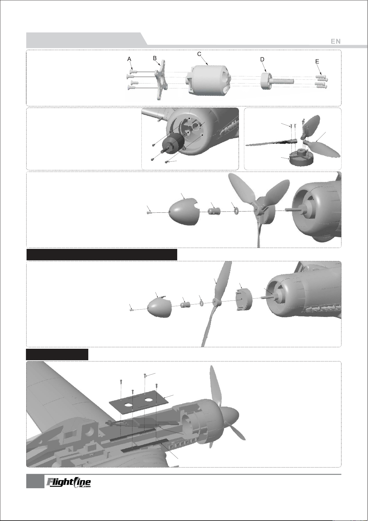
Power System Installation
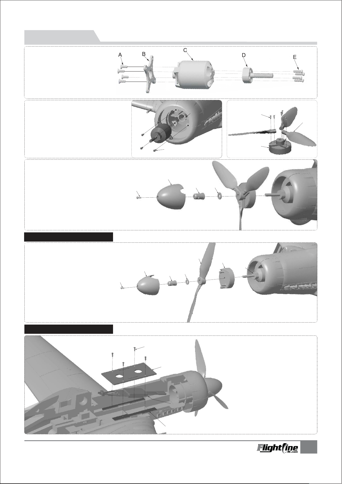
-
A
Screw
-
B
-
C
-
D
-
E
-
A
-
B
-
C
-
D
-
E
(KM3×5mm 4pcs)
Motor Mount
3648-830KV out-runner motor
Propeller folder
Screw
(HM2.5×10mm 4pcs)
Motor Mount
(PA3×12mm 4pcs)
Screw
(PA2.3×16mm 8pcs)
Screw
Scale propeller (10x6, 3-blade )
Scale propeller back plate
A
C
D
-
A
-
B
-
C
-
D
(PM3×10mm 1pcs)
Screw
Spinner (scale 3-blade spinner)
Propeller securing bolt
Washer
(Ф14×1.5×Ф6.2mm)
A
Install 2-blade propeller high power system
-
A
Screw
-
B
2-blade spinner
-
C
Propeller securing bolt
-
D
Washer
-
E
2-blade propeller
-
F
2-blade propeller back plate
-
G
3648-880KV brushless motor
An optional 2 blade high speed system
is available for this airplane. Contact
your local distributor for more
information or to purchase this option.
(Ф14×1.5×Ф6.2mm)
(12×8)
B
A
B
E
B
C
D
E
F
G
D
C
ESC Installation
9
(PWA3×8mm 4pcs)
-
A
A
Screw
-
B
Battery tray
-
C
ESC
-
D
Tray holder
B
C
Put the ESC under the battery tray, there are
D
specially designed ventilation ducts to cool the
electrical equipment effectively.
TA-152H1
Item No.:FLW05
Page 11
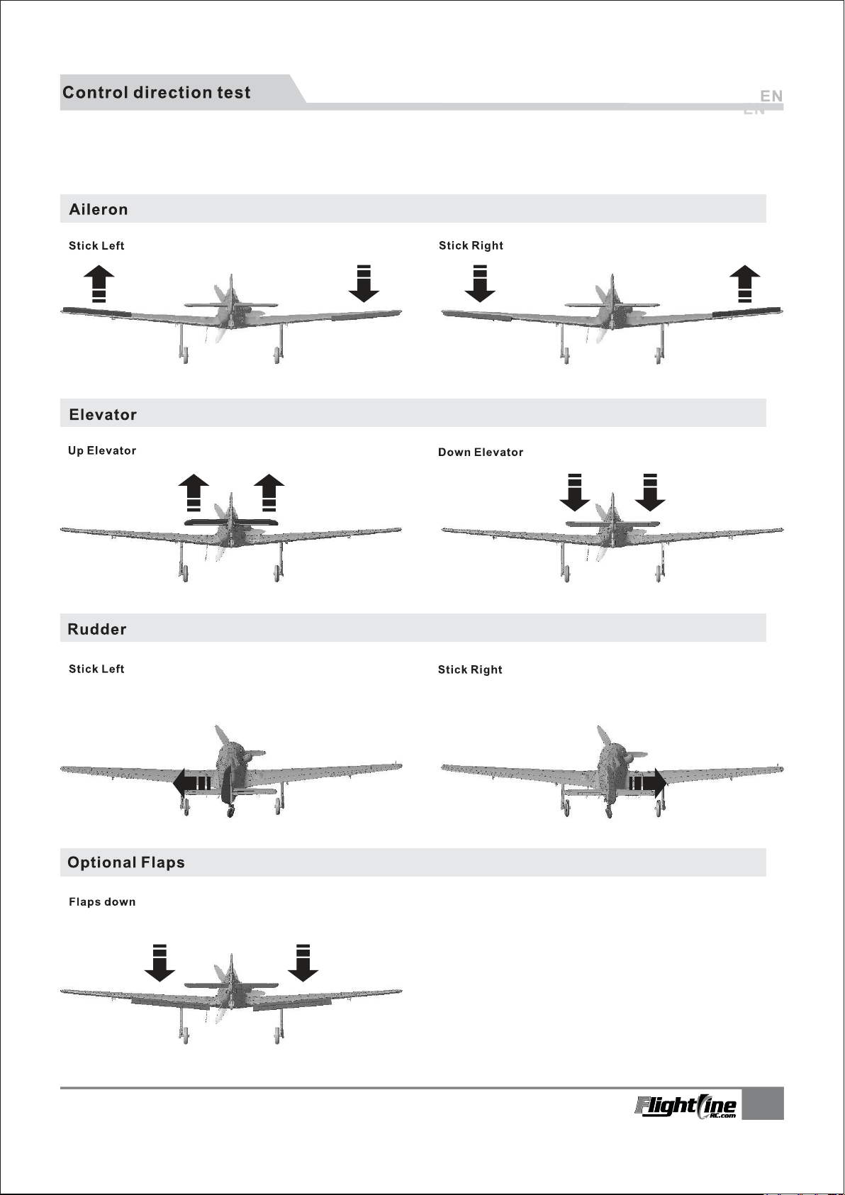
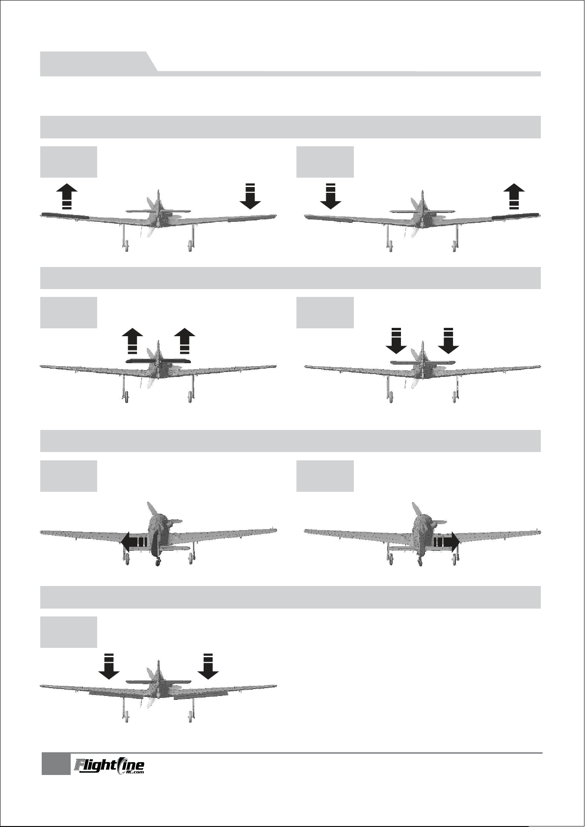
After the build is complete but with the propeller removed, power up the radio and connect a fully charged battery
to the ESC. Use the radio to ensure control direction.
TA-152H1
Item No.:FLW05
1010
Page 12
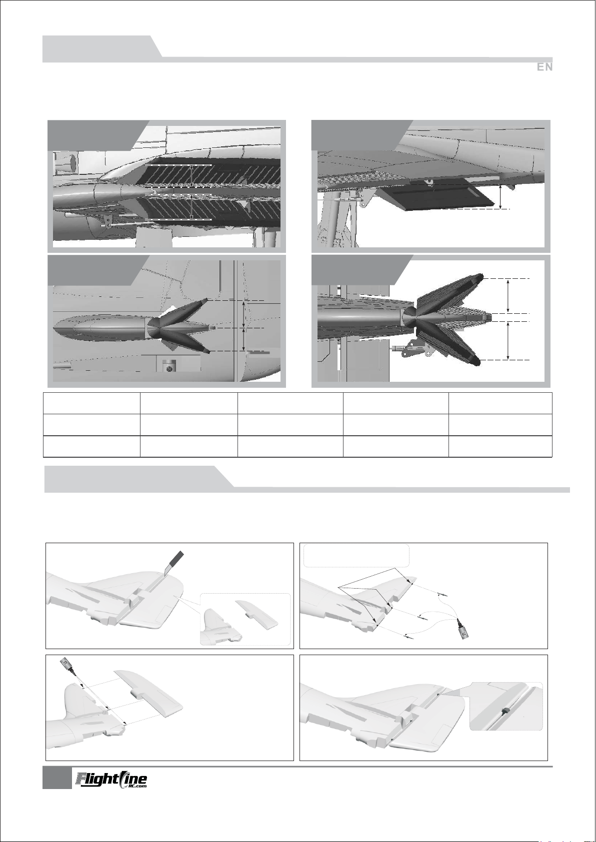
Dual Rates
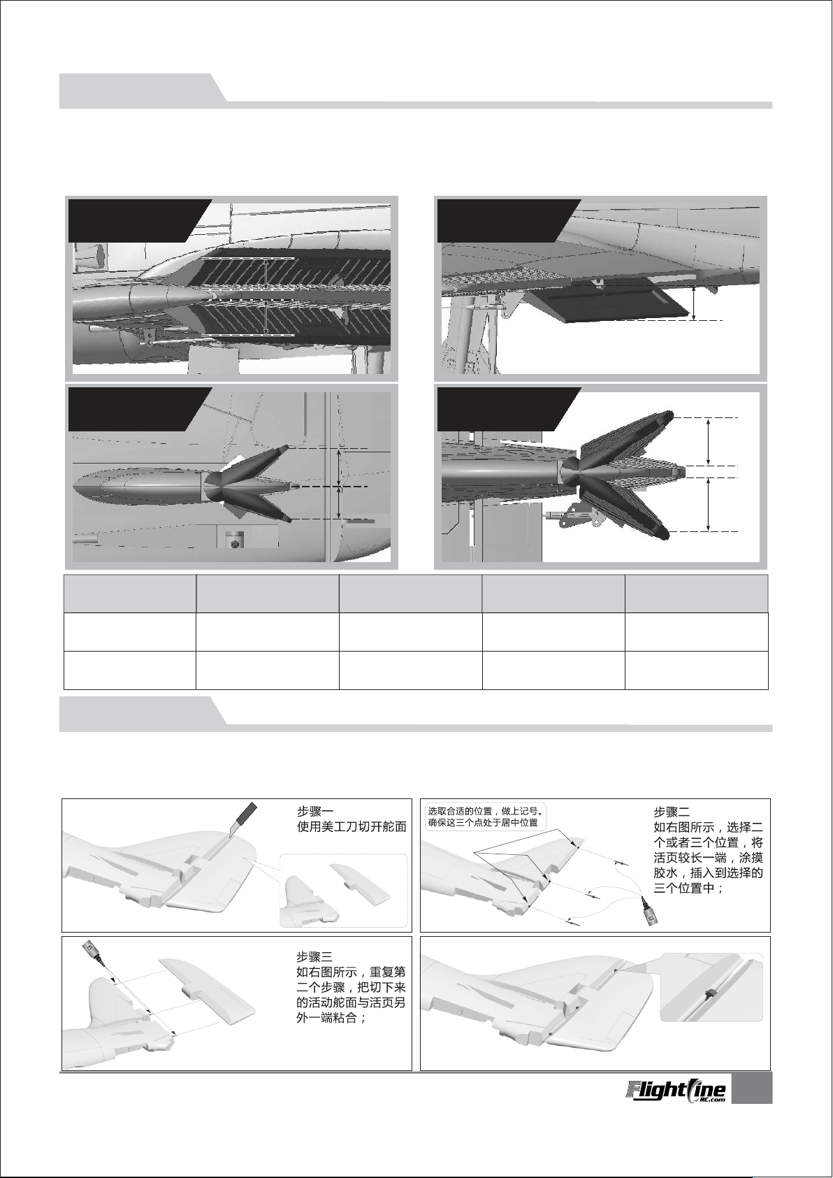
According to our test results, the following rates proved to be a good starting point. Low rates are
good for initial flights or less experienced pilots. Adjust rates to suit you own style.
Aileron
Elevator
Low Rate
High Rate
Flaps
Rudder
H1
H2
Aileron
H1/H2 10mm/10mm
D/R Rate:90%D/R Rate:85%D/R Rate:85%
H1/H2 12mm/12mm
D/R Rate:100%D/R Rate:100%D/R Rate:100%
ElevatorRudder
H1/H2 11mm/11mm
H1/H2 13mm/13mm
H1/H2 18mm/18mm
H1/H2 21mm/21mm
H1
H1
H2
Flaps
H1 15mm
H1 28mm
Installing Optional Plastic Hinges
The control surfaces of this airplane use a no-hinge connection design. Although proven reliable, these type of hinges
can be damaged due to errors, causing the control surface to become loose or separate. Included with this kit is a set of
plastic hinges if you wish to use them as an alternate or for repair.
Step one
Use a knife to remove
the control surface.
Step three
Repeat Step Two to attach
the control surface to the
stabilizer.
Select the appropriate location and
mark them. Make sure the three
points are in the middle of the
Stabilizer
Step two
Mark two or three positions, apply
glue on the long end of hinges, and
insert them into the three positions.
11
TA-152H1
Item No.:FLW05
Page 13
前 言
中文版
历史简介
Ta-152是纳粹德国在二战末期由Fw-190发展的一种高空高速活塞战斗机。与作为“快速解决方案”的Fw-190D相
比,Ta-152是作为“最终解决方案”的极致之作。由于诞生时期偏晚,生产数量太少,并未在战争中发挥太大作用;但
其优秀的性能仍获得了交战双方的一致赞赏,与P-51H、喷火XIV一起被誉为终极活塞式战斗机,其各项飞行性能已经
接近活塞式战斗机的极限。
模型介绍
飞行线1/11比例Ta-152H1模型,采用EPO材料制作,机长980mm,翼展1310mm,这款模型的外形线条及轮廓,
完全依据真实飞机制作,丰富的细节设计和细腻的迷彩喷涂,使外形更加逼真。大量的塑料零件运用,使我们可以快
速、便捷安装主翼、平尾及垂尾。模型的主翼、平尾及每个活动舵面,嵌入了玻纤管,避免高速飞行过程中出现的扭
曲、变形现象,让飞行变得更加稳定。包装盒内配送的针式活页,可以让您进一步增加舵面的可靠性。在机身内部,设
计了一条通风管道,使电子设备能够有效散热,延长寿命。用螺丝固定的电池托盘,将电池舱分为上、下二层,可以非
常方便的安装电调!随机配送的防滑垫,能够有效阻止电池的移动。这款Ta-152H1模型,采用了高功率的3648-
830KV无刷马达,配合10Х6三叶仿真桨,1200g(不含电机)的轻量化机体和硕大的电池舱空间,可以同时使用3S和4S电
池来飞行。使用3S电池时,速度达到120kph/75mph,4S电池下,速度达到140kph/88mph,同时,我们为这款模型
产品,特别提供了另外的2叶桨动力改装套件(包含:二叶桨桨罩和螺旋桨固定盘,12*8二叶桨, 3648马达),通过改
装,您可以让这款模型飞机达到高达160kph/100mph的时速,带来全新极速体验!
飞行特性
飞行线Ta-152H1模型,长翼展设计,拥有极佳的飞行稳定性和较小的转弯半径。较细的机体和强劲的动力,同时带
来优秀 的速度和爬升 性能。350mm宽 的前轮距,能够有 效抵抗起飞时 的反扭力,滑跑方向 容易保持。正常情况
下,3S/4S动力,分别需要18M/15M的滑跑距离。降落时,襟翼开启后,机头会轻微向下,我们需要略微带住少许升
舵,即可慢速、轻柔接地!
涂装介绍
模型在出厂时,已经喷涂完成。包装盒内,配送了多种机身编号的感压贴纸和贴纸说明书,您可以选择最喜欢的编
号,粘贴到机体上。
注意:模型产品是具一定危险性的产品,请禁止14岁以下的儿童玩耍,14 岁以上的儿童,请在有飞行经验的成人指导下使用,无飞行经验的购买者,应当在具有
一定电动涵道飞机飞行经验的成人指导下使用! 组装模型前,请仔细阅读说明书,按照说明书的要求进行安装. 进行调试和飞行时,请根据说明书指示的参数进行调整。
重要提示
1.模型飞机不是玩具,操作者需要具备一定的经验;没有经验的初学者,必须在有丰富经验的专业人士指引下,逐步学习!
2.在组装之前,必须认真阅读产品说明书,严格按照说明书指示操作。
3.飞翼模型及其销售商,对于违反说明书的要求操作而造成的损失、将不负任何法律责任!
4.模型飞机的使用年龄必须是14岁以上的儿童或者成人。
5.此模型产品使用EPO材料制成,表面喷涂油漆,不可随意使用化学制剂擦拭,否则会损坏模型产品。
6.不可以在公共场合、高压线密集区、高速公路附近、机场附近或者其它法律法规明确禁止飞行的场合飞行。
7.不可以在雷雨、大风、大雪或者其它恶劣气象环境下飞行。
8.模型飞机的电池产品,不可以随意乱扔,乱放。存放时,必须保证周边2M范围内,无易燃、易爆物体。
9.损坏或者报废处理的模型飞机电池,应妥善回收处理,不准随意抛弃,避免自燃而引发火灾。
10.在飞场飞行时,应做到妥善处理飞行后所产生的垃圾,不可随意抛弃、焚毁模型及其配件。
11.在任何情况下,都必须保证油门杆处于起始位、发射机处于打开状态时,才能连接模型飞机内部的动力电池.
12.无论是模型飞机是在正常飞行过程中,或者是在缓慢降落过程中,都不要尝试用手去回收模型。必须等模型降落停
稳以后 ,再进行回收!
目录
13
产品基本参数
13
包装清单
14
PNP 组装介绍
16
舵机介绍
17
控制钢丝尺寸
18
起落架组装说明
18
重心
19
电池安装
19
集线盒介绍
19
电机规格
20
动力系统安装介绍
21
舵面测试
22
大小舵及飞行注意事项
22
舵面活页改装
TA-152H1
Item No.:FLW05
12
Page 14
产 品基 本 参数
980mm(38.6")
1310mm
(51.2")
注意: 此处各项参数,均使用本公司配件测试得出,如果使用副厂配件,会有所差异。
使用副厂配件时所产生的问题,我们将无法给予技术支持!
中文版
翼载荷:88g/dm²
电机 : 3648-830KV外转无刷电机
螺旋桨 : 3叶 10×6
电调 : 60A 无刷电调
舵机 : 9g数码金属×2, 9g数码塑料×4
重量 : 1200g (不含电池)
副翼功能:有
平尾功能:有
方向舵: 有
襟翼功能:有
起落架:电动可收放起落架
舱门:主起落架舱门
机体材料:EPO
高速版本改装配件
( 以下改装配件,请联系经销商单独购买!)
专用二叶螺旋桨罩
专用二叶螺旋桨固定盘
3648-880KV 外转无刷马达
12×8 二叶桨
产 品包 装 清单
打开产品包装,核对包装清单。(不同配置的版本,包含内容不同!)
序号
1
2
3
4
5
配件名称
机身套件
主翼套件
平尾套件
贴纸
说明书
PNP
预装所有电子设备
预装所有电子设备
预装所有电子设备
KIT Plus
预装舵机
预装舵机
预装舵机
Airframe
无电子设备
无电子设备
无电子设备
序号
10
13
配件名称
6
螺旋桨
7
桨罩及固定件
8
组装塑料件及螺丝
9
玻纤管、胶水
集线控制盒
PNP
KIT Plus
Airframe
TA-152H1
Item No.:FLW05
Page 15
PNP 组 装
中文版
机身组装
注:包 装盒内有赠 送的EPO胶水 ,请使
用这支 赠送的胶水 进行粘合作 业。涂摸
胶水应 该均匀。胶 水均匀涂摸 完毕,不
要立即 粘合,请等 待90秒时间, 再进行
粘合, 效果最佳!
主翼组装
A-
B-
(Ø8mm×200mm)
碳纤管
主翼舵机线
A
1.安装前,取下电池舱盖。
2.用胶水粘将泡沫件A/B粘到机身上。
B
1.将碳纤管插入主翼上;
2.用胶水粘合左、右主翼,可进一步加强主翼强度。
B
A
3.用胶水将主翼固定塑料件A、B分别
A
C
B
螺丝
(PA3x12mm 4pcs)
粘到主翼下表面。
TA-152H1
Item No.:FLW05
5.用4颗螺丝将主翼固定到机身上。
14
Page 16
PNP 组 装
平尾安装
(Ø4x200mm)
碳纤管
A-
(KA2.3x8mm 4pcs)
螺丝
B-
B
安装尾翼 舵面控制钢丝
中文版
1.如图所示,将左、右平尾安装到机身尾部;
2.然后使用4颗螺丝固定平尾,防止松脱!
A
D
B
A
1.将方向舵控制钢丝A未装塑料夹头的一端,通过塑料管B,插入到舵机摇臂C内;
2.将方向舵控制钢丝A上的塑料夹头扣入尾舵摇臂D上。
C
B
C
D
A
1.将平尾控制钢丝A未装塑料夹头的一端,通过塑料管B,插入到舵机摇臂C内;
2.将平尾控制钢丝A上的塑料夹头扣入平尾摇臂D上。
注意:安装垂尾舵面控制钢丝时,首先需要确保我们已经将后轮
调试到居中位置;然后再安装垂尾舵面控制钢丝,并通过调节塑料夹
头,使垂直尾翼保持居中位置;
1.使用胶水把舵面摇臂粘到垂直尾翼上。
2.用垂尾控制钢丝将转向舵摇臂与垂直尾翼上的舵面摇臂
连接起来!
15
TA-152H1
Item No.:FLW05
Page 17
机体组装
机枪安装天线安装
1.将机炮A/B分别插入主翼前端。
A
B
B
登机踏板安装
2.在下图位置,钻二个小孔,使用胶水将登机踏板粘贴到
小孔中。
2.将天线C插入主翼下表面天线固定座内。
中文版
C
天线固定座
步骤
1
注意:1.完成以上步骤后,根据集线盒上的内容通道标识,将所有舵机线插入到集线盒内。
2. 最后使用胶水固定集线盒。
舵机 使用介 绍
我们的舵机正、反向标准是:
当舵机输入信号从 到 时,
如果舵机摇臂,
顺时针旋转---正向舵机
逆时针旋转---反向舵机
56
如果您需要选购其它品牌的舵机进行安装,
请参考下面的表格选择正确的舵机
舵机位置
左副翼
右副翼
左襟翼
右襟翼
垂尾
平尾
舵机规格
9g 模拟-塑料
9g 模拟-塑料
9g 模拟-塑料
9g 模拟-塑料
9g 数码-金属
9g 数码-金属
序号
1
2
3
4
5
6
正、反向
正向
正向
反向
正向
正向
正向
舵机线长
500mm
500mm
250mm
250mm
300mm
300mm
步骤
2
34
12
TA-152H1
Item No.:FLW05
16
Page 18
舵 机组装介绍
主翼舵机安装
1.通过舵机测试仪或者遥控器,把舵机摇臂校
正到居中位置;
2.用胶水分别把舵机和舵面摇臂粘到主翼;
3.将舵机线卡到舵机线槽内,待所有主翼舵机
安装完成,贴上贴纸;
4.钢丝一端穿入到舵机摇臂后,调节钢丝长度,
在保持舵面居中的情况下,将夹头扣入舵面
摇臂内;
5.重复以上4个步聚,安装襟翼舵机和另外一
侧主翼舵机。
A-
舵机
B-
主翼舵机控制钢丝
舵面摇臂
C-
主翼舵机线槽
D-
中文版
A
D
B
C
平尾、垂尾舵机安装
1.通过舵机测试仪或者遥控器,把舵机摇臂校
正到居中位置;
A-
B-
C-
()PWA2x8mm
螺丝
舵机
舵机固定座
2.使用螺丝A把舵机固定到木板上;
3.将舵机线从木板下方,放置到电池航舱内。
注意:自选舵机时,可能因为舵机尺寸的关系,无法固定。
此时,我们可以取下舵机固定木片,直接将舵机粘在木片下方的
泡沫舵机孔内,不会影响使用;
控 制钢 丝 尺寸
方向舵控制钢丝尺寸方向舵控制钢丝安装孔位
490mm
(19-1/4")
垂尾控制钢丝尺寸垂尾钢丝安装孔位
钢丝直径 Ø1.2mm
PWA2x8mm
A
C
B
41.5mm
(1-5/8")
平尾控制钢丝尺寸平尾钢丝安装孔位
490mm
(19-1/4")
副翼控制钢丝尺寸副翼舵机钢丝安装孔位
67.8mm
(3-1/8")
襟翼控制钢丝尺寸襟翼舵机钢丝安装孔位
41.5mm
(1-5/8")
钢丝直径 Ø1.2mm
钢丝直径 Ø1.2mm
钢丝直径 Ø1.2mm
钢丝直径 Ø1.2mm
2
3
1
2
3
1
2
3
17
2
3
2
3
2
3
TA-152H1
Item No.:FLW05
Page 19
起落架组装说明
主起落架组装
请参才以下图示,组装、更换、维修起落架;
D
B
C
-
前起落架主撑杆
A
-
B
-
C
-
D
-
E
-
F
-
G
-
H
(Ø65×16mm)
前机轮
(Ø5.5×Ø4.2mm)
轮档
机米螺丝
前起落架随动舱门
螺丝
电动收放控制器
机米螺丝
(M3×3mm)
(FA2×6mm)
(M3×3mm)
A
中文版
(KA2.6×12mm)
-
螺丝
A
-
起落架加强件
B
-
C
前起落架套件
-
D
起落架固定座
B
A
E
C
H
F
D
G
后起落架组装
B
1.参考右图,组装好尾轮组。
2.将尾轮组穿入后轮固定塑料件
后,继续插入到尾舵转向摇臂中;
C
3.将螺丝锁入尾舵转向摇臂进行
固定!
-
A
-
B
-
C
-
D
E - 尾舵转向摇臂
F - 后轮固定塑料件
G - 尾轮组
H - 螺丝
(Ø35×10mm)
后机轮
后轮主撑杆
后轮轮轴
(Ø5×Ø2mm)
E型扣
(PA1.6×6mm)
D
A
H
重心示意图
正确的重心,直接关系到飞行的成功与否,请参考下面的重心标示图,来调整飞机的重心。
-您可以将电池向前,或者向后移动,来调整飞机的重心;
-如果通过电池的移动无法调整到正确的重心位置,您还
可以适当的使用一些其它材料来配重,使飞机的重心处
于正确的位置!
72mm
(2-13/16")
G
F
E
TA-152H1
Item No.:FLW05
18
Page 20
电池 安装说 明
向上提,
胶纸
取下电池
舱罩
电池舱罩
电池
中文版
电池安装好后,用魔术带绑紧
魔术扎带
电池托盘
将电池与接收机连接前,首先请打开发射机电源,
确认油门杆处于低位。
安装电池后,启动油门前,请保证没有任何物体在
螺旋桨转动直径以内,避免造成事故和人身伤害!
集线盒 使用 说明
单闪灯
起落架
方向
升降
副翼舵机
襟翼舵机
起落架及接收机供电
电机参数
单闪灯
起落架
方向
升降
副翼舵机
襟翼舵机
襟翼
方向
升降
副翼
电池舱尺寸:2006540mm
我们建议使用的电池容量和放电倍率如下:
3S 11.1V 2600mAh ~ .
3S 111V 4000mAh
4S 14.8V 2600mAh ~ 4S 14.8V 4000mAh
放电倍率 30C
>
参考集线盒上的通道标识,将所有电池舱
内的连接线插入集线盒。接线工作完成
接收机
后,使用胶水固定集线盒,防止松动。
xx
电机安装尺寸
4-M3.0
25
单位: 毫米(mm)
Item No.
MO136483
MO136484
KV
Value
830 RPM/V
880 RPM/V
Volate
(V)
14.8
14.8
电机桨夹、十字架参数
Ø9.0
11.0
8.8
单位: 毫米(mm)
24.0
19
Ø9.6
Ø6.0
5
47
3648-830KV / 3648-880KV
Current
(A)
41
53
Pull
(g)
2500
2600
Motor
Resistance
0.02
0.02
Ø20
4-Ø2.6
12.5
18.0
2.3
Weight
(g)
170
165
11.5
53.0
Ø9.0
∅12.0
12.5
No Load
Current
2.3A/10V
2.3A/10V
4-Ø3.2
4-Ø3.2
25
.5
43
Ø37.5
4-M2.5
Propeller
3-Blade10×6
2-Blade12×8
ESC
60A
60A
3.0
TA-152H1
Item No.:FLW05
Page 21
动力系 统的 安装
螺丝
(KM3x5mm 4pcs)
A-
电机固定十字架
B-
3648-830KV无刷外转马达
C-
螺旋桨桨夹
D-
(HM2.5x10mm 4pcs)
螺丝
E-
电机固定座
-
A
螺丝
-
B
C
D
E
(PA3×12mm 4pcs)
(PA2.3×16mm 8pcs)
螺丝
-
仿真螺旋桨()
-
仿真螺旋桨固定盘
-
10×6,三片组合
A
中文版
C
D
(PM3×10mm 1pcs)
螺丝
-
A
螺旋桨桨罩 (仿真三叶桨罩)
-
B
螺旋桨固定栓
-
C
垫片
(Ф14×1.5×Ф6.2mm)
-
D
A
2叶高速版改装套件的安装
-
A
B
C
D
E
F
G
我们为这款模型准备一个2叶高速改装套件,有效提高
功率和飞行速度,降低螺旋桨的使用成本!您可以向
我们的经销商联系购买专和改装套件
(PM3×10mm 1pcs)
螺丝
-
二叶螺旋桨桨罩
-
螺旋桨固定栓
-
(Ф14×1.5×Ф6.2mm)
垫片
-
-
-
(12×8)
二叶桨
二叶螺旋桨固定盘
3648-880KV无刷马达
B
A
B
E
B
C
D
E
F
G
D
C
无刷电子调速器安装
TA-152H1
Item No.:FLW05
A-
螺丝
(PWA3x8mm 4pcs)
B-
A
电池托盘
电调
C-
托盘固定架
D-
B
C
电调放置在电池托盘B下方,这里
是一个特别设计的通风管道,可
以有效对电子设备降温。如左侧
D
图示,当我们取下电池托盘B时,
您可以方便地更换电调!
20
Page 22
舵面测试
当您按前面的步骤组装好飞机后,在飞行前,我们需要用一块充饱电的电池,连接到电调。用遥控
器测试每个舵面的工作情况,检查是否正常!
中文版
副翼
副翼摇杆
向左运动
升降舵
升降摇杆
向下运动
副翼摇杆
向右运动
升降摇杆
向上运动
方向舵
方向摇杆
向左运动
襟翼
襟翼放下
方向摇杆
向右运动
21
TA-152H1
Item No.:FLW05
Page 23
大、 小舵参 数
根据我们的测试经验,我们认为,按以下参数来设置副翼和升降舵的大、小舵,将有助于飞行。
在小舵角的情况下,飞机的可操控性能会好一些,适合初次飞行或者不太熟练的玩家飞行。而大舵角
的设置,可以提高动作灵敏度,使用经验丰富的玩家。您可以根据自身的情况,来选择其中一种舵量
进行飞行!
中文版
副翼襟翼
H1
升降舵
方向舵
H1
H1
小舵角
大舵角
副 翼
H1/H2 10mm/10mm
舵量比率:90%
H1/H2 12mm/12mm
舵量比率:100%
H2
升降舵方向舵襟 翼
H1/H2 11mm/11mm
舵量比率:85%
H1/H2 13mm/13mm
舵量比率:100%
H1/H2 18mm/18mm
舵量比率:85%
H1/H2 21mm/21mm
舵量比率:100%
H1 15mm
H1 28mm
H2
舵面 活页改 装
本产品舵面,采取无铰链方案设计,虽然经过大量的运用,已经证明这是一种可靠的设计,但
是,我们不排除,在使用的过程中,由于失误而造成舵面脱落现象。所以,我们随机配送了 一套塑
料针式铰链,方便您的维修和舵面加强,请参考以下示意图,进行改装:
TA-152H1
Item No.:FLW05
22
Page 24

R
Dongguan Freewing Electronic Technology Ltd
HK Freewing Model International Limited
Add.:
FeiYi Building,face to Labor Bureau, Fumin Middle Road, Dalang Town,
Dongguan City,Guangdong Province, China
Web: http://www.sz-freewing.com
Email:[email protected]
Tel: 86-769-82669669 Fax:86-769-82033233
东莞市飞翼电子科技有限公司
香港飞翼模型国际有限公司
地址: 广东省东莞市大朗镇富民中路402-408号飞翼楼四楼
Web: http://www.sz-freewing.com
Email:[email protected]
Tel: 86-769-82669669 Fax:86-769-82033233
 Loading...