

Page 1
B-24 LIBERATOR
USER MANUAL
WINGSPAN:2000MM(78.7in.)
LENGTH:1230MM(48.4in.)
WEIGHT:2190G (W/O BATTERY)
EN
中
1~11
12~22
Page 2
The famed B-24 Liberator is one of the most recognizable WWII aircraft of all time. Serving in every theater of
that global conflict, the B-24 fought to bring its brave crews home through unimaginable danger. With humility and
reverence, FlightLineRC and Motion RC are proud to introduce the world’s first foam electric PNP B-24 Liberator, in
remembrance of the crews who gave the ultimate sacrifice and those who carry on its memory.
The FlightLineRC B-24 is approximately 1/16 scale, with a 2000mm wingspan and 1230mm length. Constructed from
EPO foam and reinforced with integrated aluminum, carbon, and plastic structures, the B-24 delivers the ultimate all
around experience for pilots seeking the ultimate foam PNP bomber replica. A magnetic nose section allows owners to
swap between two B-24 variants, the -D (”Greenhouse” nose), and the -J (”Emerson turret” nose). The Upper Turret on both
variants and the Nose Turret on the -J variant can be panned with an optional servo. Steerable tillers are pre-installed,
including special provisions to fit FPV cameras inside.
The FlightLineRC B-24 uses four 3530-860KV brushless outrunner motors and four 30A ESCs. A quick
disconnect ribbon wire harness consolidates wiring into a central circuit board in the fuselage. The recommended
pair of 4s 14.8V 2800-4000mAh lipo batteries 2pcs can power the aircraft in excess of 110kph/70mph, for 4-10
minutes based on a pilot’s throttle management. The outboard motor pair and inboard motor pair are run from
separate flight batteries, allowing for powered landings in the event of one battery failing. A 70mm tall nose wheel
and 85mm tail main wheels provide stable operation grass runways, and optional suspension struts are available.
Assembly is comprised of only 12 screws and gluing on external details such as antennas.
1. This is not a toy! Operators should have some basic experience. Beginners should operate only under the guidance of a professional
instructor.
2. Before beginning assembly, please read through the instructions and carefully follow them throughout the build.
3. Freewing and it's vendors will not be held responsible for any losses due to improper assembly and operation.
4. Model airplane operators must be at least 14 years of age.
5. This airplane is made of EPO foam material, covered with surface spray paint. Don't use chemicals to clean as it may cause damage.
6. You should avoid flying in areas such as public places, areas with high voltage power lines, nearby highways, airports or in other areas
where laws and regulations clearly prohibit flight.
7. Do not fly in bad weather conditions, including thunderstorms, snow, etc...
8. Lipo batteries should be properly stored in a fire proof container and be kept at a minimum of 2M distance away from flammable or
explosive materials.
9. Damaged or scrap batteries must be properly discharged before disposal or recycling to avoid spontaneous combustion and fire.
10. At the Flying Field, properly dispose of any waste you have created, don't leave or burn your waste.. Ensure that your throttle is in the
low position and that your radio is turned on before connecting the Lipo battery.
11. Before connecting the batteries, make sure your transmitter is powered up, with the correct channel selected and the throttle in the
lowest position. If you have a kill switch, engage it as well.
12. Do not try to catch the airplane while in flight. Do not touch the airplane until it comes to a complete stop and the propellers stop
turning.
Catalog
Introduction
Basic Product Information
Package List
PNP Assembly Instructions
Wire Pull-Through Tool Instruction
Horizontal Stabilizer/Vertical Stabilizer Assembly..
Propeller Assembly and Installation....................................
Main Wing Installation .......................................................
Magnetic nose cone Installation.........................................
Scale Accessories Installation............................................
Pushrod instructions
1
Control board connection diagram
2
Battery Size
2
Center of Gravity
Servo Direction
3
Motor Specifications
3
X-Mount & Motor shaft
3
Power system Installation..............................
4
Control Direction Test
4
5
Dual Rates and Flight Precautions................
5
6
7
7
8
8
9
9
10
11
1
B-24 LIBERATOR
Ite n No.:
Page 3
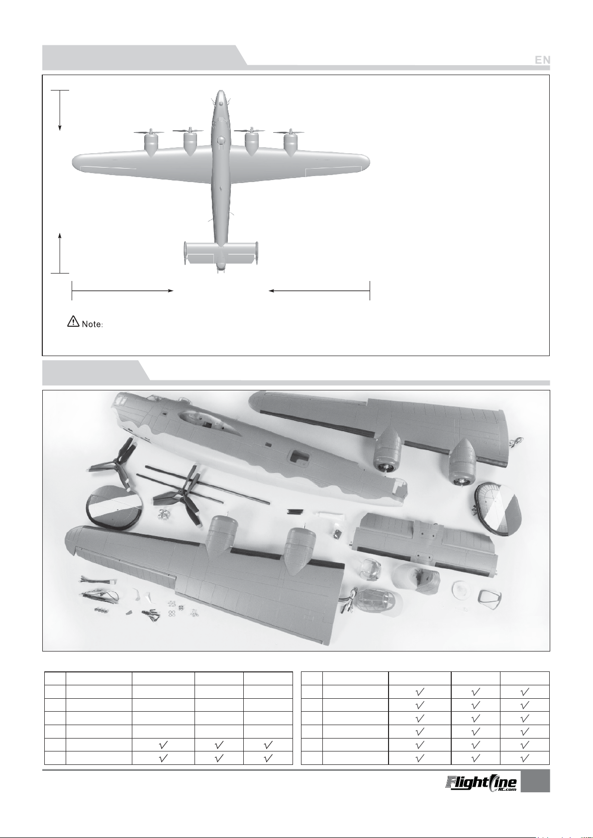
Basic product information
1230mm(48.4in.)
2000mm(78.7in.)
The parameters stated here are derived from test results using our accessories.
If you use other accessories, the test results will differ. We cannot provide
technical support if you have a problem when using other accessories.
Wing loading100g/dm²:
Wing:35dm² area
Motor: 3530-860KV
brushless outrunner motor (4pcs)
r-Blade Popeller : 39.5x7
(4Piecs Standard/Reverse)
ESC : 30A(4pcs)
Servo : 9g digital metal gear servo (9pcs)
Flight speed110KPH/70MPH:
Empty Weight : 2910g(without battery)
5400gPull:
Material:EPO
Aileron: Yes
Flaps: Yes
Elevator: Yes
Rudder: Yes
Landing gear: Retractable, Suspension
Scale Pilot figure
Battery: 4S 2800-4000mAh (2pcs)
Package list
Different types of kits will come with specific parts. Please refer to the list to confirm your kit's contents.
No.Name
Fuselage
1
Main wing
2
Horizontal tail
3
Vertical tail
4
Propeller & Spinner
5
Nose Turret & Nose
6
B-24 LIBERATOR
Ite n No.:
Pre -inst alled a ll
ele ctron ic part s
Pre -inst alled a ll
ele ctron ic part s
Pre -inst alled a ll
ele ctron ic part s
Pre -inst alled a ll
ele ctron ic part s
PNP
ARF Plus
Pre -inst alled
ser vo
Pre -inst alled
ser vo
Pre -inst alled
ser vo
Pre -inst alled
ser vo
Airframe
No el ectro nic
equ ipmen t
No el ectro nic
equ ipmen t
No el ectro nic
equ ipmen t
No el ectro nic
equ ipmen t
No.Name
Scale Accessories
7
8
ESC wire
9
Linkage Set
Glue & Non-slip mat
10
Carbon tube & Screw
11
Manual & Decals
12
PNP
ARF Plus
Airframe
2
Page 4
PNP Assembly Instructions
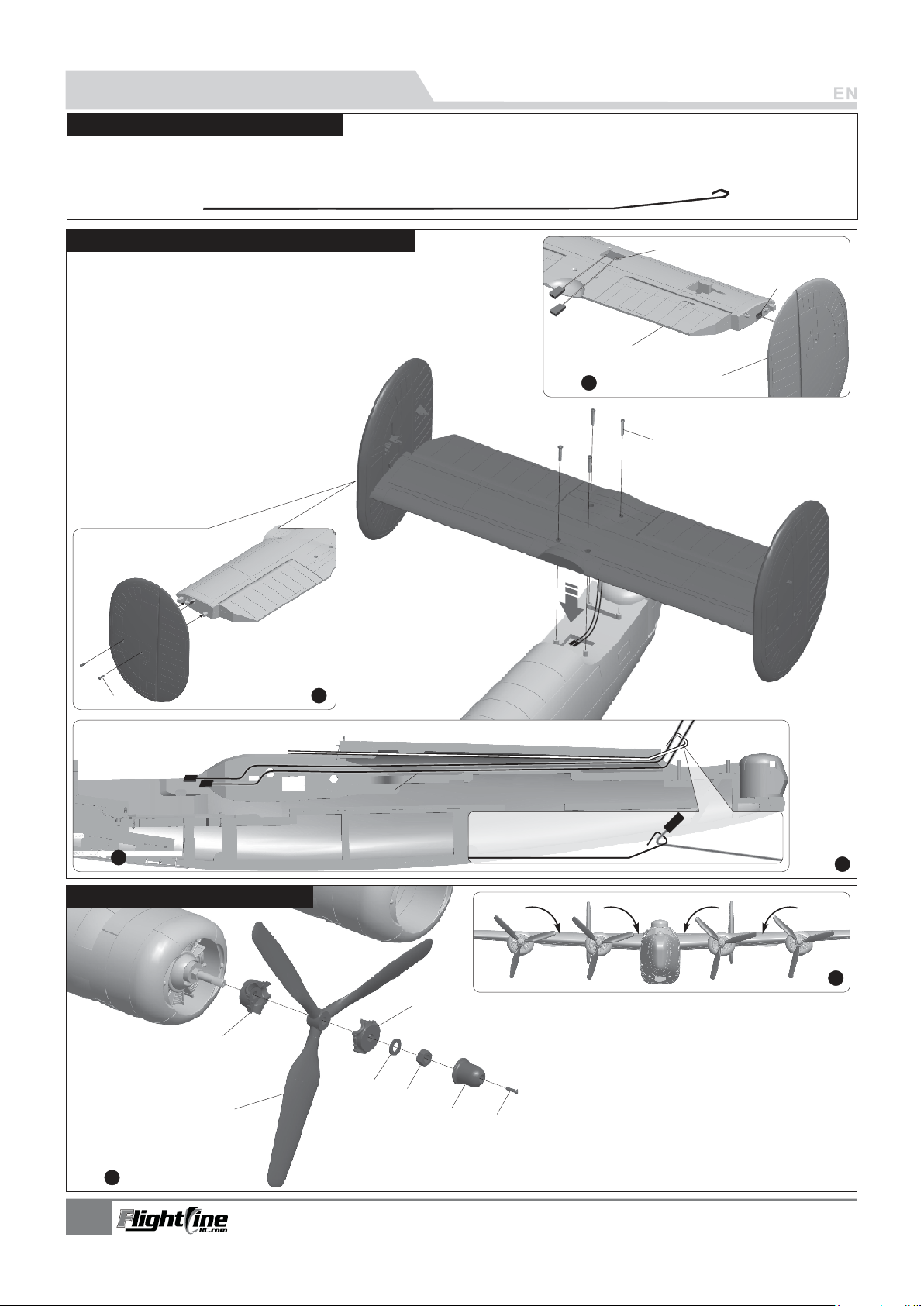
Wire Pull-Through Tool Instructions
Our tests show that excessively long servo extension lines increase the risk of poor connections that can lead
to servo brown outs or failure, causing accidents during flight. Instead, this kit contains a steel wire that can
be used to pull the main wing/elevator and rudder servo wires through the airplane to the battery compartment
Horizontal Stabilizer/Vertical Stabilizer Assembly
As shown in the photo below:
1.Insert the left and right rudder servo cables into the trough of the
horizontal stabilizer, and pull the cables through the gap.
2.Secure the left and right vertical stabilizers to the horizontal stabilizer
with 4 PA3x8 screws.
3.As shown in the photo, bundle the rudder/elevator cables and use the
Wire Pull-Through Tool to feed the cables to the battery compartment.
4.Finally, install the horizontal stabilizer to the fuselage
and secure it with 4 PA3x8 screws.
A-
Rudder
Elevator
B-
C-
Servo cable
D-
Elevator wire trough
E-
F-
(PA3x8 4pcs)
Screw
Screw (PA3x8 4pcs)
Step
C
D
B
1
F
A
E
Battery compartment
Step
3
Propeller Assembly and Installation
G
F
Step
1
Step
Steel wire tool
2
Elevator and Rudder servo cables
E
D
C
Referring to the photo:
1.Attach the propeller to the propeller shaft。
2.Make sure that the propellers are installed on the correct
side. Refer to the photo above.
B
A
Step
Step
A-
B-
C-
D-
E-
F-
G-
(PM2.5x6 4pcs)
Screw
Spinner
Screw nut
Washer
Propeller hub, front (A)
Scale propeller
Propeller B hub, front (B)
4
2
3
B-24 LIBERATOR
Ite n No.:
Page 5
PNP Assembly Instructions
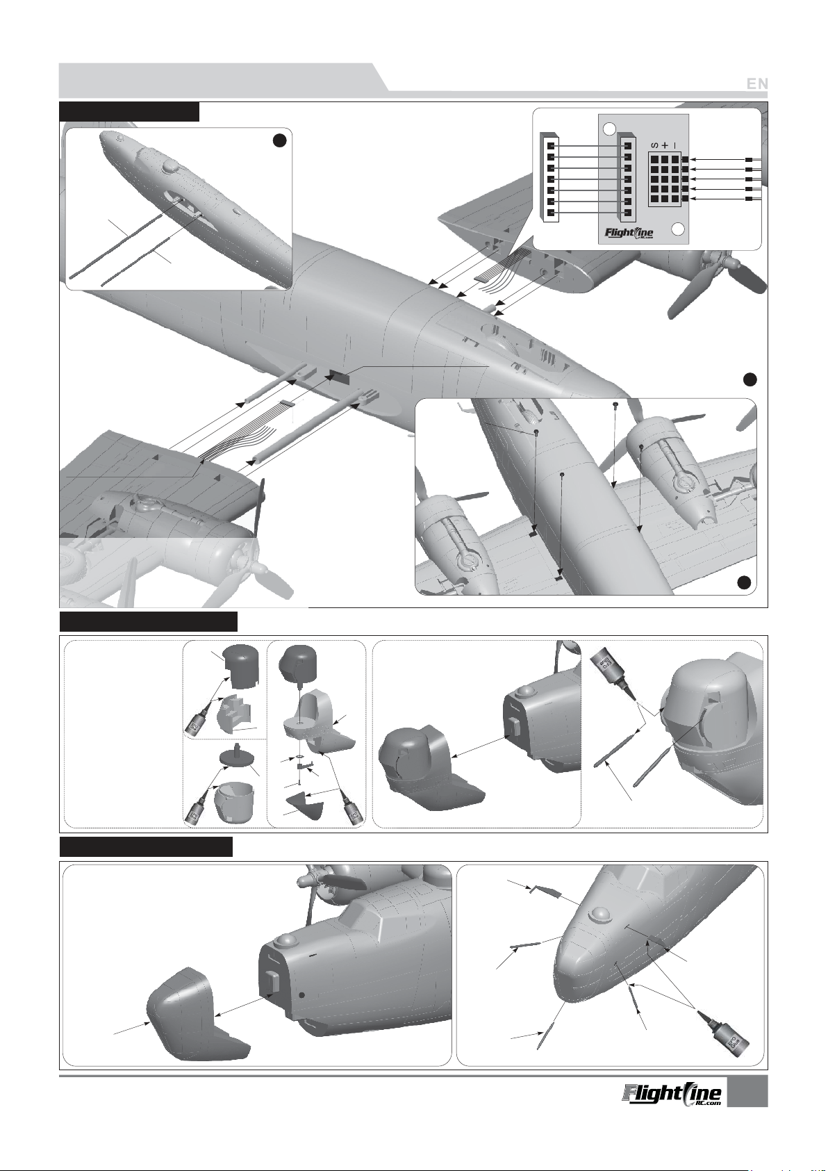
Main Wing Installation
Step
1
Carbon tube A
(Ø10x500mm)
CBarbon tube
(Ø8x360mm)
ESC wire & Ribbon wire
Main wing wire hole
Screw
(PWM4x8 4pcs)
3
3
1
6
5
Thr ottle
Thr ottle
Ail eron
Fla p
Lan ding ge ar
Step
2
1.Insert carbon tube A and B into the fuselage.
2.Pull the ESC wire and Ribbon wire through the hole.
3.Slide the left and right main wings to the fuselage.
4.Use 4 PWM4x8 screws to secure the main wings.
Nose Section -J Installation
A-
Nose Turret A
Nose Turret B
B-
Nose Turret Base
C-
B-24-J
D-
Variant Foam Nose
Washer
E-
Tiller
F-
G-
H-
I-
(PA2.3x8)
Screw
Lower Windshield
Gun Barrels
(PNP includes two optional forward nose sections for the B-24-D (”Greenhouse”) and B-24-J (”Emerson Turret”)
A
D
B
E
C
G
F
H
Nose Section -D Installation
A-
Greenhouse for -D Variant
B-
Antennas
Gun Barrels
C-
Magne
Step
3
t
I
B
A
B-24 LIBERATOR
Ite n No.:
Magnet
C
C1
C2
B1
4
Page 6
PNP Assembly Instructions
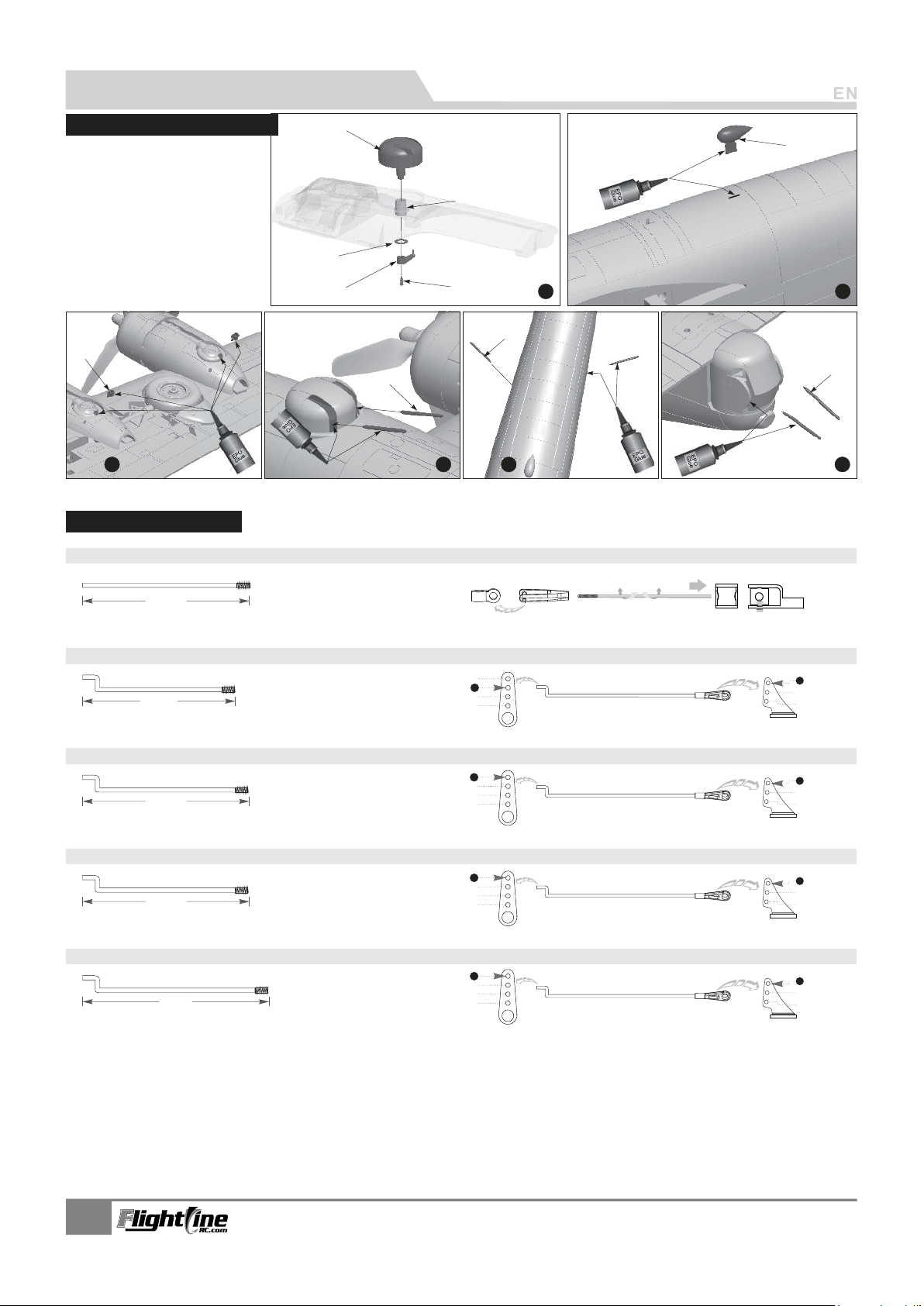
Scale Accessories Installation
A -
Upper Turret Base
B -
Washer
C-
Tiller
D-
Screw
E -
Antenna
F -
Exhaust Pipe
G-
H -
Gun Barrels
rretUpper Tu
(PA2.3x8)
G
Step
3
Pushrod Length Setup
Nose gear steering pushrod length
A
F
B
C
D
E
Step
1
Step
2
H1
H2
H
Step
Step
4
5
Nose gear steering pushrod mounting hole
Step
6
45mm
(1- 3/4")
Flap pushrod length
33mm
(1- 5/16" )
Aileron pushrod length
41.5mm
(1- 5/8")
Elevator pushrod length
41.5mm
(1- 5/8")
Rudder pushrod length
53mm
(2- 1/16" )
Pushrod diameter Ø1.2mm
Pushrod diameter Ø1.2mm
Pushrod diameter Ø1.2mm
Pushrod diameter Ø1.2mm
Pushrod diameter Ø1.2mm
Flap pushrod mounting hole
1
2
3
4
Aileron pushrod mounting hole
1
2
3
4
Elevator pushrod mounting hole
1
2
3
4
Rudder pushrod mounting hole
1
2
3
4
1
2
3
1
2
3
1
2
3
1
2
3
5
B-24 LIBERATOR
Ite n No.:
Page 7
PNP Assembly Instructions
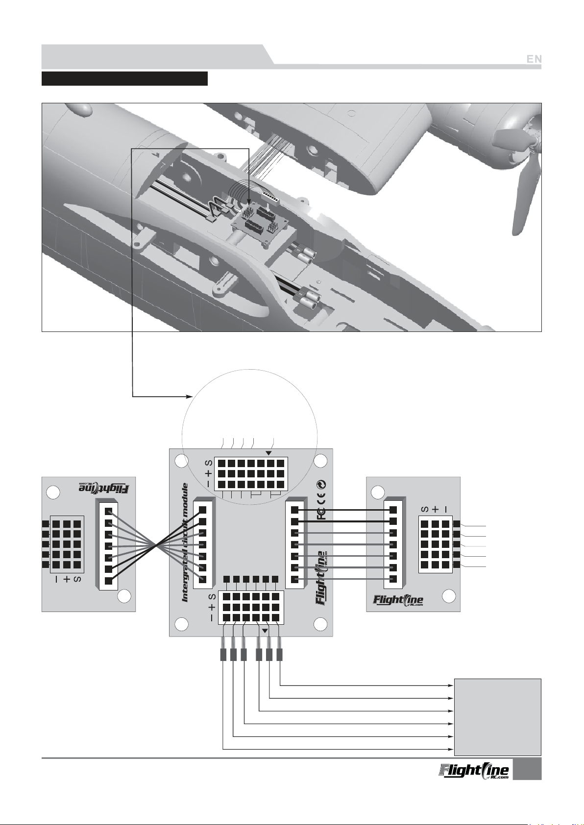
Control board connection diagram
The B-24 uses a convenient flexible ribbon wire harness to consolidate wiring. Refer to the photo for the proper wiring configuration.
Nose Landing gear door servo
Nose Landing gear retract
Nose steering servo
Rudder servo
Elevator servo
Ser vo lnpu t
Main wing control board(Right) Main wing control board(Left)
GEAR
5
6
1
3
3
B-24 Liberator
GEAR DOOR
FLAP
6
Nose Steering
GEAR
5
Rec eiver
E LE
RUD
A IL
THR
RUD
E LE
4
1
2
3
Connect to the Aileron channel in the receiver
Connect to the Elevator channel in the receiver
Connect to the Throttle channel in the receiver
Connect to the Rudder channel in the receiver
Connect to the landing Gear channel in the receiver
Connect to the Flap channel in the receiver
3
3
1
6
5
Throttle
Throttle
Aileron
Flap
Landing gear
Receiver
B-24 LIBERATOR
Ite n No.:
6
Page 8
PNP Assembly Instructions
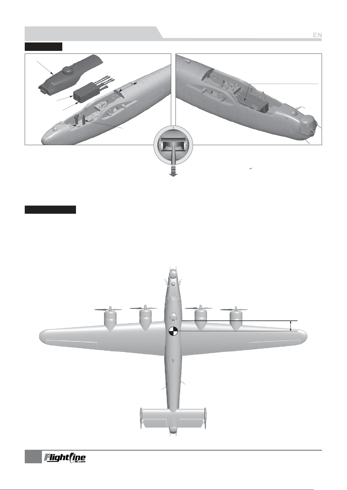
Battery Size
Cockpit
ull the latch back
P
Battery A
Battery B
and open the cockpit.
Use rubberized non-slip tape
or hook-and-loop tape
Battery tray
Velcro
Battery cabin size:
L=160 W=98 H=68(mm)
Before connecting the batteries to the ESC for the first time,
please remove the propellers, position the model on a stand
above the ground. and switch on the transmitter power. Ensure
the throttle stick is in the lowest position. Engage the kill switch if
you have one assigned
After you have programmed your radio transmitter, reinstall the propellers and carefully verify their correct rotation. With the aircraft level, the
uppermost tips of all the propellers should rotate inward, toward the fuselage. The stock PNP configuration assigns the inboard motors to one
flight battery, and the outboard motors to the second flight battery. If one battery fails, the model can be landed immediately on the remaining
two engines flown at full power. Before all flights, ensure all areas forward of the propellers are clear to avoid injury.
Center of Gravity
Correct Center of Gravity (
following CG diagram to adjust your aircraft’s Center of Gravity. This CG has been flight tested 200+ times for your safety.
CG”) is critical for enabling safe stable flight performance and responsive control. Please refer to the
”
- Depending on the capacity and weight of your choosen
flight batteries, move the battery forward or backward to
adjust the Center of Gravity.
- If you cannot obtain the recommended CG by moving the
battery to a suitable location, you can also install a suitable
counterweight to achieve correct CG. However, with the
recommended battery size, a counterweight is not
required. We recommend flying without unnecessary
counterweight.
We recommend the following LiPo batteries:
4S 14.8V 2800mAh ~ 4S 14.8V 4000mAh (x2)
Discharge rate of C
>
35C
76mm
(3")
7
B-24 LIBERATOR
Ite n No.:
Page 9
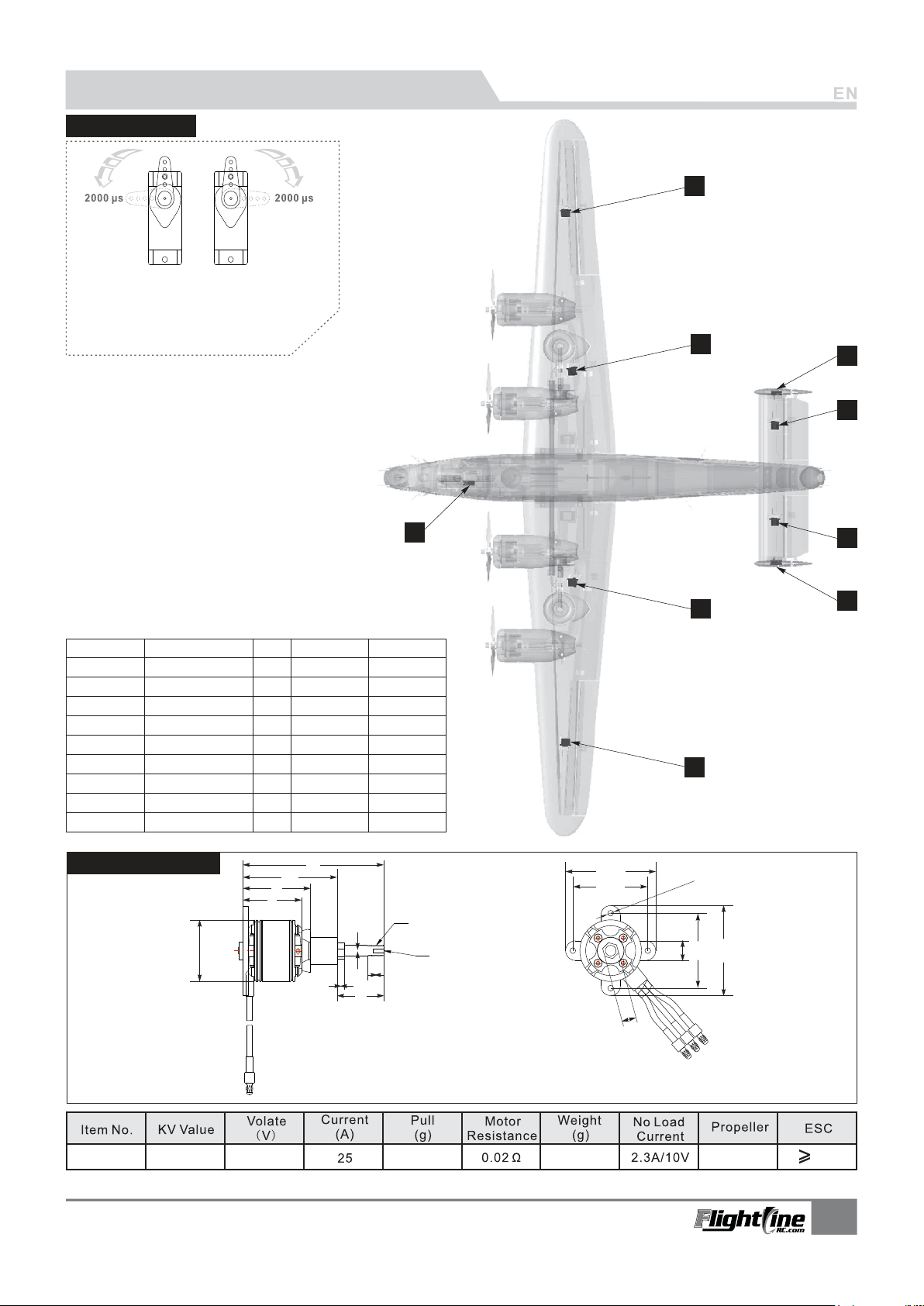
Pre-Installed Component Overview
Servo Direction
A servo or reversed servo is defined as follows:
When the servo input signal changes from
1000ųs to 2000ųs, if the servo arm rotates
clockwise, it's a positive servo.
If it rotates counter clockwise, it's a
reversed servo.
2
4
8
6
1
Note: If you choose not to use the factory servos, the servos you
choose may be a different size. Use the following chart to ensure
that the servos you choose are compatible with this airplane.
Position
Nos e gear
ste ering s ervo
Aileron(L)
Aileron(R)
Flap(L)
Flap(R)
Elevator(L)
Elevator(R)
Rudder(L)
Rudder(R)
Servo regulation
9g Digital-MG
9g Digital-MG
9g Digital-MG
9g Digital-MG
9g Digital-MG
9g Digital-MG
9g Digital-MG
9g Digital-MG
9g Digital-MG
Motor Specifications
Ø35
No.
1
2
3
4
5
6
7
8
9
33
38
Pos./Rev.
53
Positive
Positive
Positive
Positive
Positive
Positive
Positive
Positive
Positive
79
4
Cable length
400mm
750mm
750mm
250mm
250mm
850mm
850mm
950mm
950mm
Ø6
9.0
26
M6
M2.5
51. 5
41. 5
7
5
9
3
4-Ø3,2
11
41. 5
51. 5
7.9
860RPM/V
B-24 LIBERATOR
Ite n No.:
14.81350
106
3530-860KV
Units:mm
3-Blade 9.5x7
30A
8
Page 10
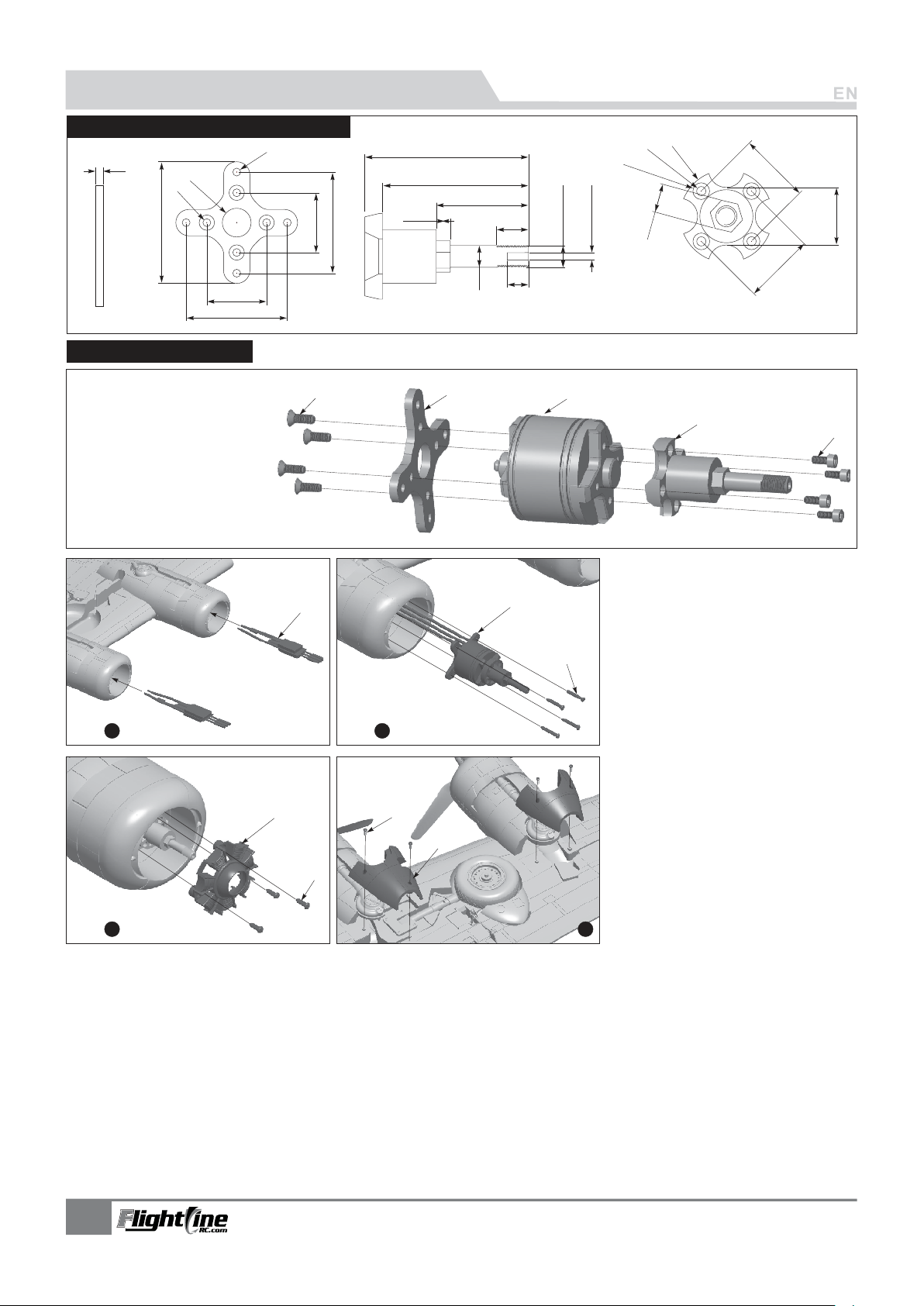
Pre-Installed Component Overview
X-Shaped Motor Mount & Propeller Shaft
25.0
41.5
Ø3.2
25.0
41.5
3.0
51.5
Ø3.2
Ø12.0
Power system Installation
A-
B-
C-
D-
E-
(PM3x6)
Screws
Motor Mount
3530-860KV out-runner motor
Prop shaft adapter
Cup head screws
(M2.5x6)
A
A
Step
1
Step
Ø26
46
41
26
4
9.0
Ø6
B
M6 External thread
M2.5 Internal thread
6
C
Ø4.7
Ø2.6
20
16
7.9
20
Units:mm
D
E
Refer to the left diagrams 1 and
2 to install the ESC's and
B
C
2
Motors.
A-
ESC
Motor
B-
C-
Screws (PA3x15 16pcs)
D-
Engine cowl
E-
Screws
F-
Engine Pod cover
Screws
G-
(PA2.3x6 12pcs)
(PA2.3x6 8pcs)
Step
Refer to the left diagrams 3 and
4 to install the dummy radial engines
D
G
and engine pod covers.
F
E
3
Step
4
9
B-24 LIBERATOR
Ite n No.:
Page 11
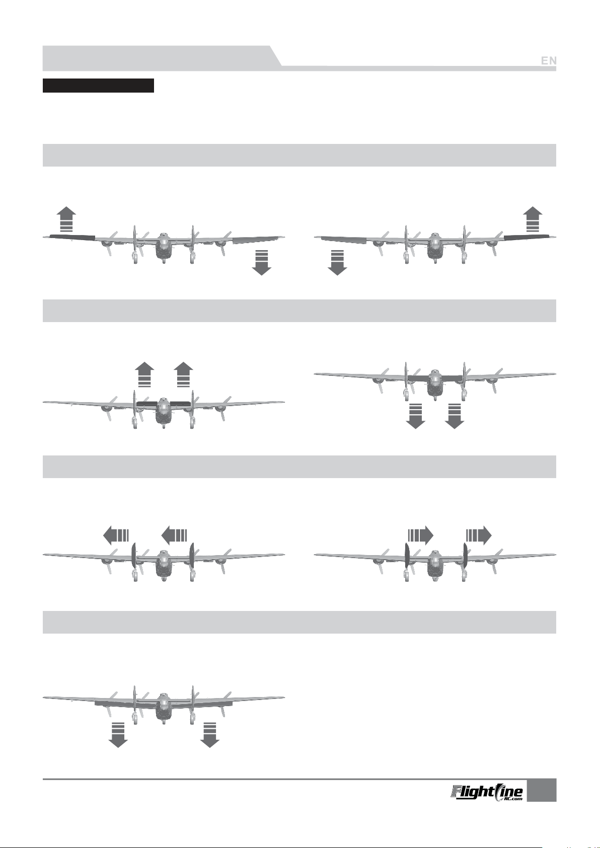
Control Setup Instructions
Control Direction Test
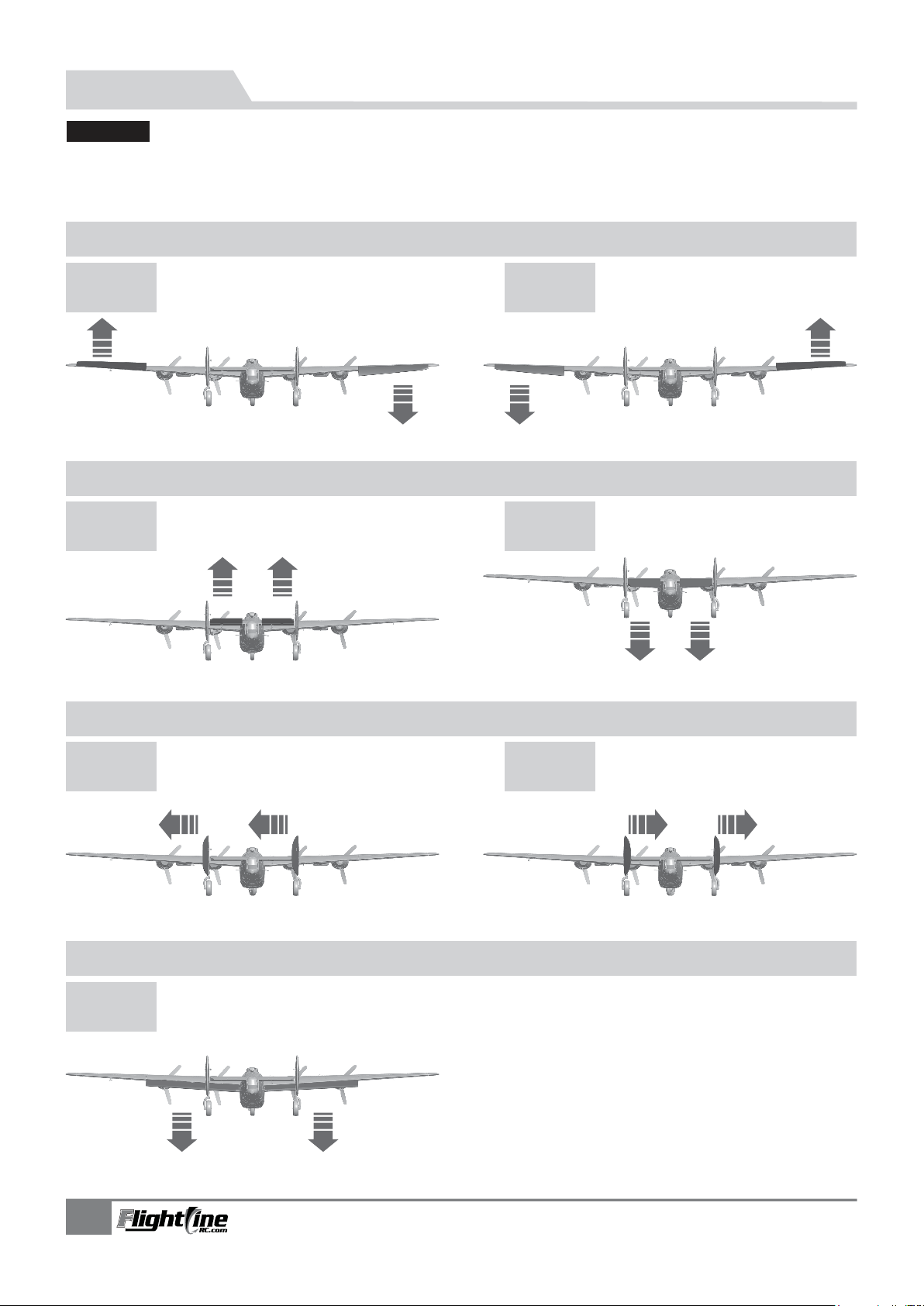
After the build is complete but with the propellers removed, power up the radio and connect two fully charged
batteries to the ESC's. Use the radio to ensure correct control direction.
Aileron
Stick LeftStick Right
Elevator
Stick Back Stick Forward
Rudder
Stick LeftStick Right
Flaps
Flaps down
B-24 LIBERATOR
Ite n No.:
10
Page 12
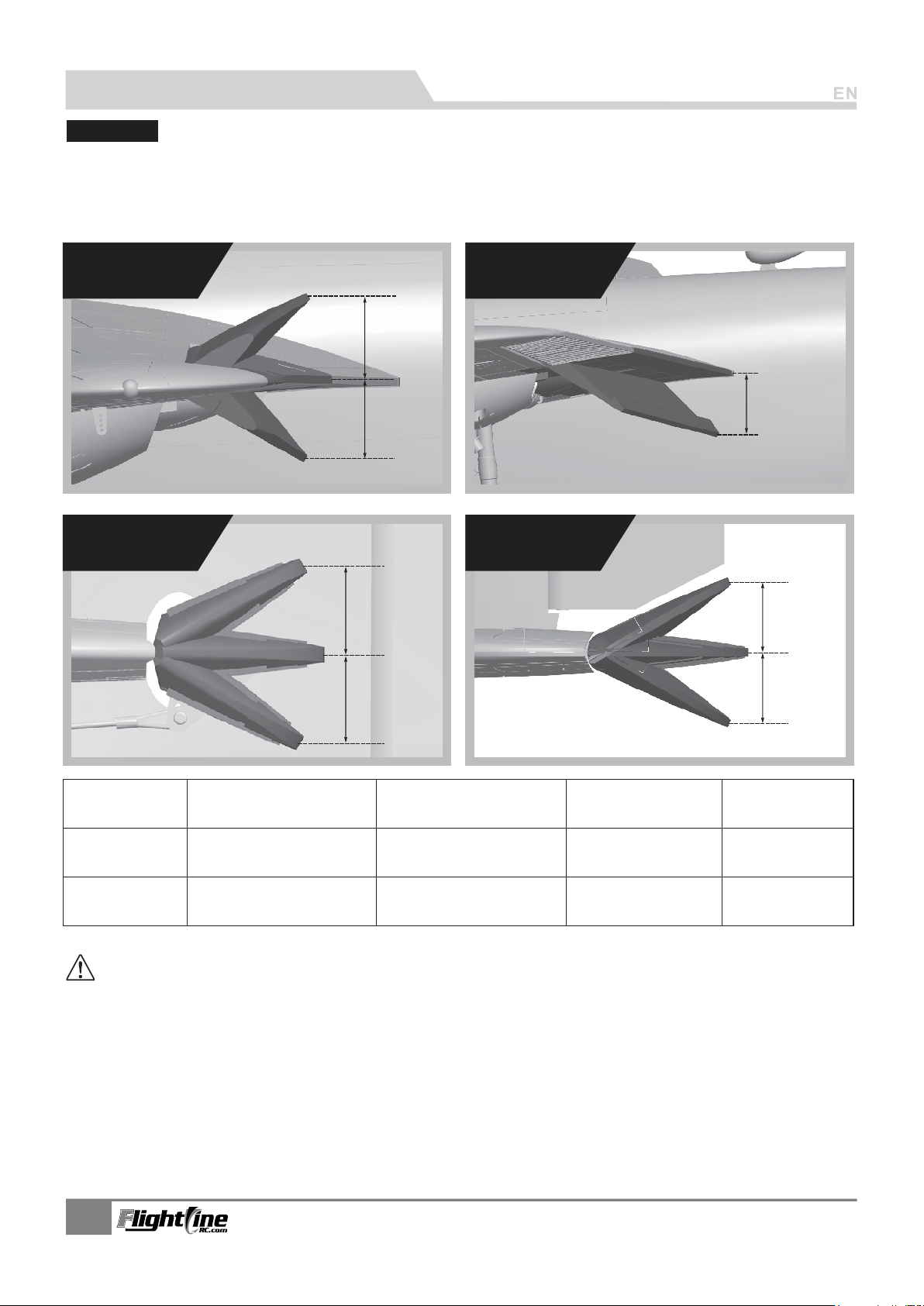
Control Setup Instructions
Dual Rates
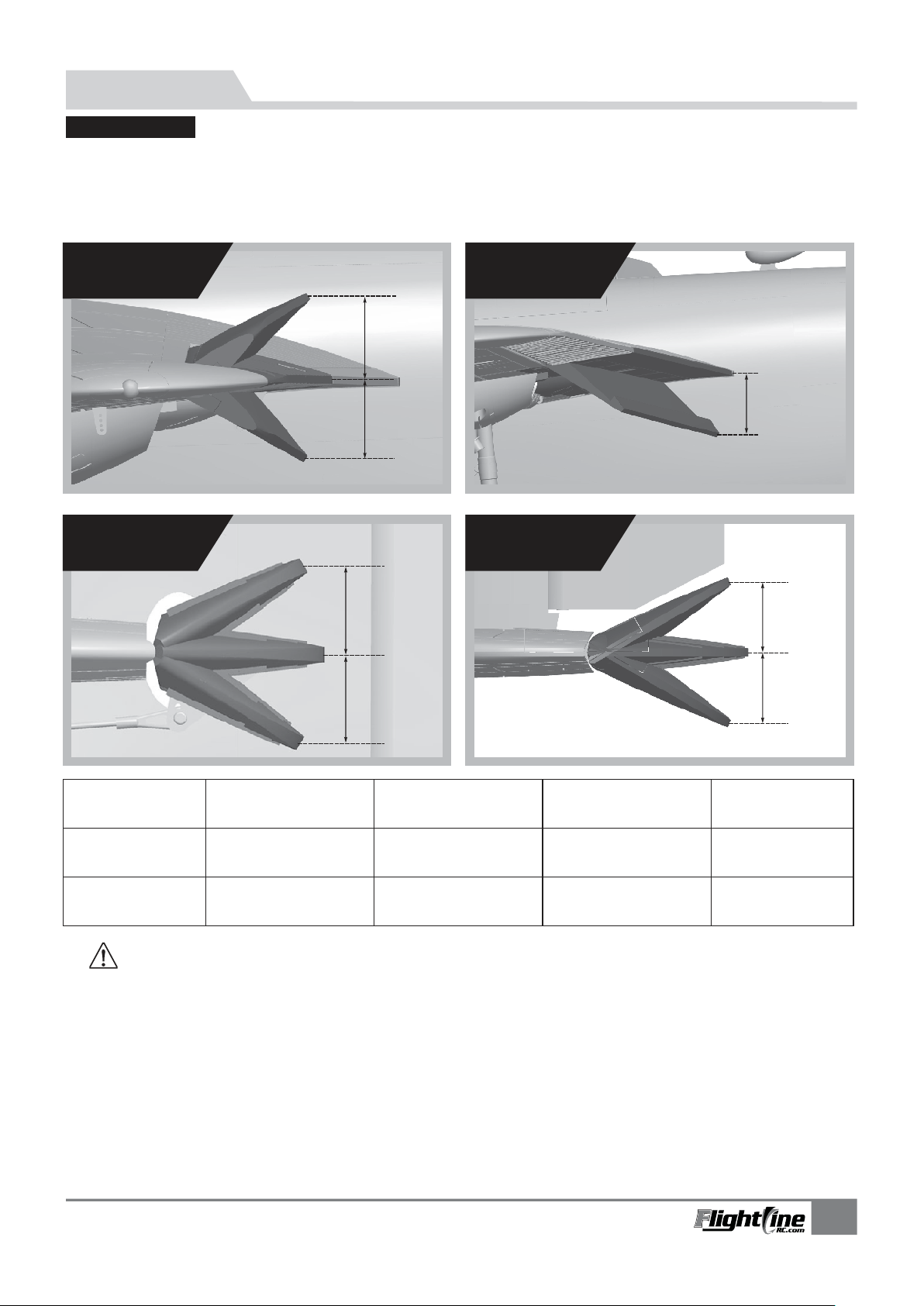
With reference to our Flight Test data, we recommend the following parameters to set the Aileron/
Elevator Rate. Program your preferred Exponential % in your radio transmitter. We recommend using High Rates
for the first flight, and switching to Low Rates if you desire a lower sensitivity. On successive flights, adjust the
Rates and Expo to suit your preference.
AileronFlaps
H1
H2
ElevatorRudder
H1
H2
Elevator(measured closest
to the fuselage)
H1/H2 18mm/18mm
D/R Rate:75%
Low Rate
Aileron(measured closest
to the fuselage)
H1/H2 20mm/20mm
D/R Rate:85%
Rudder(Measured
from the bottom)
H1/H2 15mm/15mm
D/R Rate:80%
H1
H1
H2
Flaps
H1 13mm
High Rate
IMPORTANT:
Throttle Calibration
Before your first flight, remove the propellers and calibrate your ESC pairs and verify that all four motors are synchronized.
Reinstall the propellers and taxi test the model to check for synchronous thrust.
Flap Mixing and Tips
1 - A Flap-to-Elevator Mix is required to maintain level flight when the flaps are deployed. With 13mm of flaps(Low Rate),
mix 1.5mm of Down Elevator. With 29mm of flaps (High Rate), mix 3mm to Down Elevator.
2 - When flaps are deployed, do not advance the throttle very quickly. The B-24 is intended to be flown as a scale bomber,
with moderate throttle advance. Add rudder input to flatten turns for more scale appearance.
Elevator Neutral Position
1. Before your first flight, mechanically set the Elevator's Neutral Position to 1.5mm Up.
H1/H2 22mm/22mm
D/R Rate:100%
H1/H2 23mm/23mm
D/R Rate:100%
11
H1/H2 19mm/19mm
D/R Rate:100%
B-24 LIBERATOR
H1 29mm
Ite n No.:
Page 13
PNP 组装说明
舵面 测试
中文版中文版
当您按前面的步骤组装好飞机后,在飞行前,我们需要用一块充饱电的电池,连接到电调。用遥控
器测试每个舵面的工作情况,检查是否正常!
副翼
副翼摇杆
向左运动
升降舵
升降摇杆
向下运动
方向舵
副翼摇杆
向右运动
升降摇杆
向上运动
方向摇杆
向左运动
襟翼
襟翼放下
方向摇杆
向右运动
21
B-24 LIBERATOR
Ite n No.:
Page 14
PNP 组装说明
大、 小舵参数
中文版中文版
根据我们的测试经验,我们认为,按以下参数来设置大小舵量,将有助于飞行。小舵量
飞机的操纵会笨拙些,大舵量飞机的操纵会灵敏些,我们建议初次飞行使用大舵量起飞,然
后视操纵习惯选用小舵量或者大舵量飞行。
副翼
升降舵
H1
H2
襟翼
H1
H1
H2
方向舵
H1
H2
副翼(内侧)
小舵量
大舵量
特别注意事项:
前检测:飞行
第一次飞行此产品或者更换遥控器后,必须校准油门,这样才能保持4套动力产生的拉力一致,具体校正方法见
电调说明书。
飞行前设定:
1. 降落开襟翼飞机抬头比较明显,需要混控点降舵才能很好降落,小舵量襟翼需要1.5mm降舵,大舵量襟翼需
要3mm降舵
2. 升降舵调平飞机飞行会有比较明显的低头现象,这样需要1.5-2mm升舵飞机就能够很好的平飞;
3. 放下襟翼飞行时,我们需要较柔和的增加油门,不能瞬间加大油门量,否则会出现飞机突然向下飞行,容易
造成飞机坠毁事故.
B-24 LIBERATOR
Ite n No.:
H1/H2 20mm/20mm
舵量比率:85%
H1/H2 22mm/22mm
舵量比率:100%
升降舵(内侧)
H1/H2 18mm/18mm
舵量比率:75%
H1/H2 23mm/23mm
舵量比率:100%
方向舵(下端)
H1/H2 15mm/15mm
舵量比率:80%
H1/H2 19mm/19mm
舵量比率:100%
襟翼
H1 13mm
H1 29mm
22
Page 15

R
Dongguan Freewing Electronic Technology Ltd
HK Freewing Model International Limited
Add.:FeiYi Building,face to Labor Bureau, Fumin Middle Road, Dalang Town,
Dongguan City,Guangdong Province, China
Web: http://www.sz-freewing.com
Email:[email protected]
Tel: 86-769-82669669 Fax:86-769-82033233
东莞市飞翼电子科技有限公司
香港飞翼模型国际有限公司
地址: 广东省东莞市大朗镇富民中路402-408号飞翼楼四楼
Web: http://www.sz-freewing.com
Email:[email protected]
Tel: 86-769-82669669 Fax:86-769-82033233
 Loading...