

Page 1

www.sz-freewing .com
EN
1 ~ 12
中
13 ~ 24
Spitfire MK IXc
SUPERMARINE
User Manual
Wingspan : 1200mm
Item No.: FLW203
MADE IN C HI NA
D
E 25 ~ 42
Page 2

1
Spitf ireMK.IX c
It emNo. :FLW 203
Index
Page
2- Introduction
3- Product Basic Information Package List
4- Assembly: Main Wing Servos and Wing Installation
5- Assembly: Tail Wheel Gear, Elevator, Rudder
6- Assembly: Elevator and Rudder pushrods
Assembly: Installing Radiators, machine guns, mirror,
antenna and Air Intake Scoop. Main Landing Gear
2- Servo Introduction, Battery Installation
3- Power System/ Propeller/ ESC Installation
4- Motor Parameters/ Center of Gravity
5- Control Direction Setup
6- Dual Rates/ Installing optional plastic hinges
7- Build Notes
Page 3
2
Spitf ireMK.IX c
It emNo. :FLW 203
Introducing FlightLineRC, the new brand from Freewing Models! FlightLineRC will bring you a
new series of propeller driven aircraft at the same level of quality and value you trust
from Freewing. Flightline brings to you the outstanding innovation, exquisite design, high quality,
unbeatable value, and dependable performance you come to expect from Freewing. Thank you for
purchasing the FlightLineRC 1200mm Spitfire Mk. IXc!
Overview:
The Supermarine Spitfire is one of the most popular warbirds in history. This British singleseat fighter was used by the Royal Air Force and the Allies, earning distinction during the
Battle of Britain and throughout World War II. Over 20,300 aircraft were produced with more than
24 variants. The Spitfire's versatility and maneuverability made it a lethal aircraft against Axis forces,
such as the Focke Wulf FW-190. The Spitfire continues to fly in modern times as a tribute to
aviation history and military veterans.
Features:
FlightLineRC's Spitfire is the popular Mk. IXc variant. Over 5,000 of this variant were built
in World War II. The classic Spitfire colors are factory painted and included with the kit are two
decal sets so you can choose which scheme you want to install on your Spitfire. The first decal set
is for MK392, flown by the RAF Ace, James Edgar “Johnnie” Johnson in August 1944. The
second decal set is for MJ586, flown by the French Ace, Pierre Clostermann in October 1943.
This Spitfire Mk. IXc is approximately 1/9.5 scale, with a 1200mm wingspan. Molded
from EPO foam, the main wing and horizontal tail are attached with screws, allowing these
parts to be easily removed for transport. Only a few parts require glue and assembly is less
than one hour! The battery bay is large and uses a magnetic hatch to close it securely.
Servos are easily accessible for maintenance or replacement and proper
ventilation has been designed to keep the electronics cool. The electronic retracts
use metal reinforcement plates and the split flaps, plastic parts, and surface details give
your Spitfire lots of scale realism.
Power System:
The stock PNP version is equipped with a 3748-580KV brushless outrunner motor and scale 4-
blade propeller. W ith the recommended 4s 14.8v 4000mAh lipo battery, the Spitfire Mk. I Xc is very
agile and has a level top speed of 135kph / 83mph. An optional “High Power Upgrade Set” can be
purchased separately t o obtain a level top speed of 1 50kph/93mph. This Upgrade Set includes one
3648-880KV motor, a 1 2x8 2 -blade propeller, and a 2-blade spinner.
( Conversion kit is sold separately, please contact MotionRC.com)
1. This is not a toy! Operators should have some basic experience. Beginners should operate only under the guidance of a
professional instructor.
2. Before beginning assembly, please read through the instructions and carefully follow them through the build.
3. Freewing and it's vendors will not be held responsible for any losses due to improper assembly and operation.
4. Model airplane operators must be at least 14 years of age.
5. This airplane is made of EPO foam material, covered with surface spray paint. Don't use chemicals to clean as it may cause
damage.
6. You should avoid flying in areas such as public places, areas with high viltage power lines, nearby highways or airports or an
other areas where laws and regulations clearly prohibit flight.
7. Do not fly in bad weather conditions, including thunderstorms, snow, etc...
8. Lipo batteries should be properly stored in a fire safe container and be kept at a minimum of 2M distance away from
flammable or explosive materials.
9. Damaged or scrap batteries must be properly discharged before disposal or recycling to avoid spontaneous combustion and
fire.
10. At the Flying Field, properly dispose of any waste you have created, don't leave or burn your waste.. Ensure that your throttle
is in the low position and that your radio is turned on before connecting the Lipo battery.
11. Do not try to catch the airplane when flying low or landing. Wait for the airplane and its propeller to come to a complete stop.
Page 4
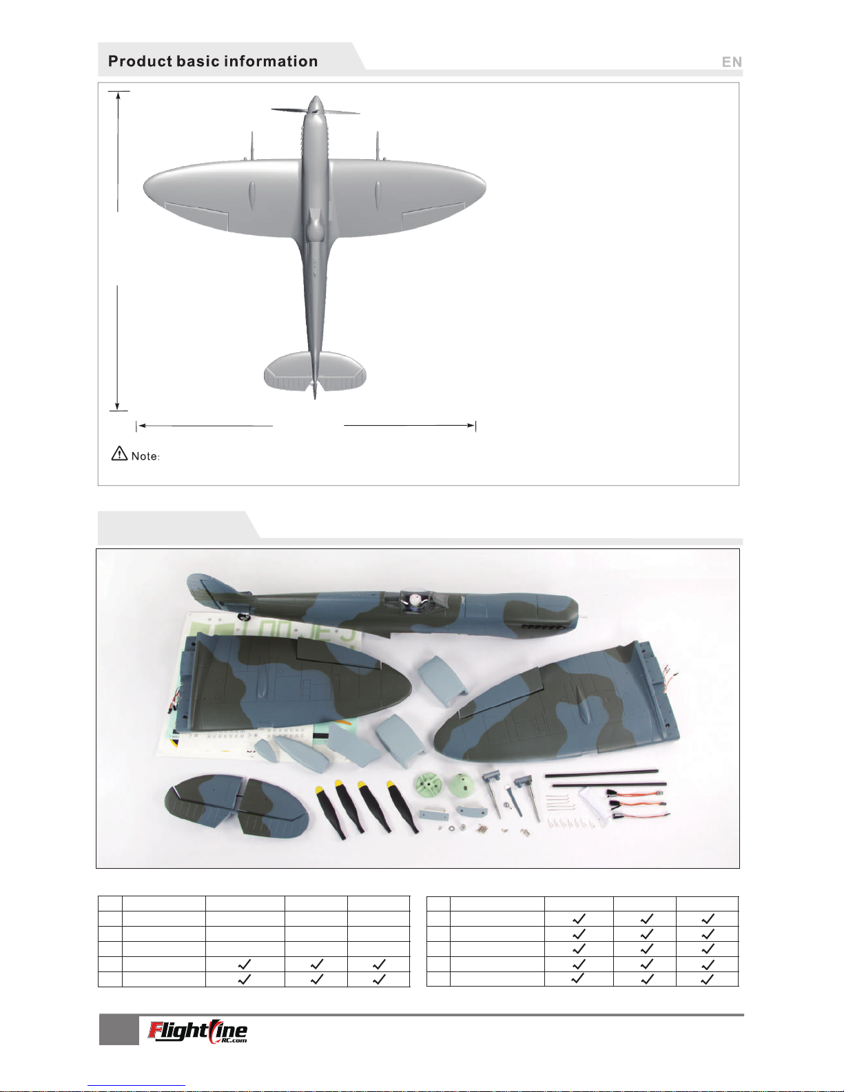
1085 mm
1200 mm
(47- 1/ 4")
(42- 1 / 2")
Wing loading:68g/dm²
Motor:3748-580KV brushless mo tor
Propeller:4-blade 12×7
ESC: 60A brushless ESC
Servo:9g MG×2, 9g plastic×4
Weight: 1400g (w/o battery)
Aileron: Yes
Elevator: Yes
Rudder: Yes
Flap: Yes
Landing gear: retract landing gear
Cabin door
Material: EPO
(The following is DIY sp ar e-pa rt, please contact
distributor to pu rchase s ep arat ely.)
2-blade propeller spinner
2-blade propeller fixed plate
3648-880KV brushless moto r
2-blade 12×8 propeller
High speed DIY spare-part
Package list
Different equipment include differ en t sp ar ep ar ts. Pl ease refer t o the following conten ts t o check your s pa re pa rt list.
Fuselage
Main wing
Tail wing set
Foam parts
"Y" wire
No.
Name
No el ectronic
equipment
Pre-i nstalled al l
elect ronic parts
Pre -installe d
servo
PNP
ARF Plus
ARF
ARF Plus
ARF
1
2
3
4
5
No el ectronic
equipment
Pre-i nstalled al l
elect ronic parts
Pre -installe d
servo
No el ectronic
equipment
Pre-i nstalled al l
elect ronic parts
Pre -installe d
servo
No.
Name
PNP
6
7
8
9
10
Propeller
Spinner & fixed part
Installed part & screw
Fiberglass tube & glue
Manual
3
Spitfir e MK.IXc
It em N o.: FLW203
The parameters stated here are derived from test results using our accessories.If you use other
accessories, the test results will differ. We cannot provide technical support if you have a problem
when using other accessories.
Page 5

Fiberglass tube size:Ø8mm×280mm (2 pcs)
5
1.
2.
3.
Use a servo tester or radio to center the
serv o.
Use glue to install the servo and aileron
horn on the main wing.
Feed the servo wires into the slot, after
installing all the servos, apply the decal
over the wire slot.
4.Insert one side of the pushrod into the
servo arm, adjust its length. And insert the
clevis to the aileron horn. Slide the rubber
retainer over the clevis
5.Repeat the above four steps for the other
wing aileron and flap servos
.
Assembly
Installing main wing servos
A - 9g servo
B - Main wing pu sh ro d
C - Aileron horn
D - Main wing servo wire slot
Main wing
Step 1
Use glue to attach the part A to the fuselage.
Installing the main wing
Step 2
Use gl ue to attac h left/ right mai n wing.
Step 3
Use gl ue to attac h the mai n
wing f ixed pl astic par t B,C on
the ma in wing .
Step 4
Use 4p cs scre ws to fix the
main w ing.
Note: There is EPO glue in the kit,
please use it for assembly. For best
results, glue should be
spread evenly,
then wait for 90 seconds before joining.
Aileron push ro d si ze
Flap pushrod s iz e
Aileron push ro d mo un ti ng h ol e
Flap pushrod m ou nt in g ho le
Pushrod diameter : Ø 1.2mm Pushrod diameter : Ø 1.2mm
B
C
A
D
A
PA3×10m m
4
Spitf ireMK.IX c
It emNo. :FLW 203
55m m
(2- 1/5")
68m m
(2- 4/ 5")
Page 6

A
B
C
D
-
-
-
-
(Ø35× 10 mm )
A
B
C
D
1
2
3
(Ø5×Ø 2m m)
(PA1 .6 ×6 mm)
Ø4 mm ×2 50m m
(KA3×mm )
A - Tail steering arm
B - Rear ge ar f ix ed p lasti c pa rt
C - Tail gear set
D - Screw
Install the tail wheel gear assembly
1.Refer to the photo at right, for proper
tail wheel assembly installation.
2.Insert the tail gear set C to the fixed
plastic part B, then insert tail steering arm A
3. Use screw D to fix the
tail steering arm.
Rear whe el
Rear gea r su pp or ti ng r od
Rear whe el s ha ft
E-buck le
1. Use servo tester or radio to center the
servo.
2.Use screw A to fix the 9g servo to the
wooden piece.
3.Insert the servo cable under the wooden
piece, and feed it to the battery
compartment.
Elevator, Rudder
Install the Elevator/rudder servos.
Note: If you choose not to use the factory servo,
the chosen servo may be larger. If that is the case, you
need to remove the fixed wooden piece and glue the
servo into position in the fuselage.
A - Fiberglass tube
B - Screws
Install elevator
Assembly
A
B
C
D
A
B
PWA 2×8mm
B
A
1. Referring to the above photo, install the left/right elevator on the tail of t he fuselage.
2.Turn
the fuselage over, and use
4 screws to secure the elevator.
5
Spitf ireMK.IX c
It emNo. :FLW 203
Page 7
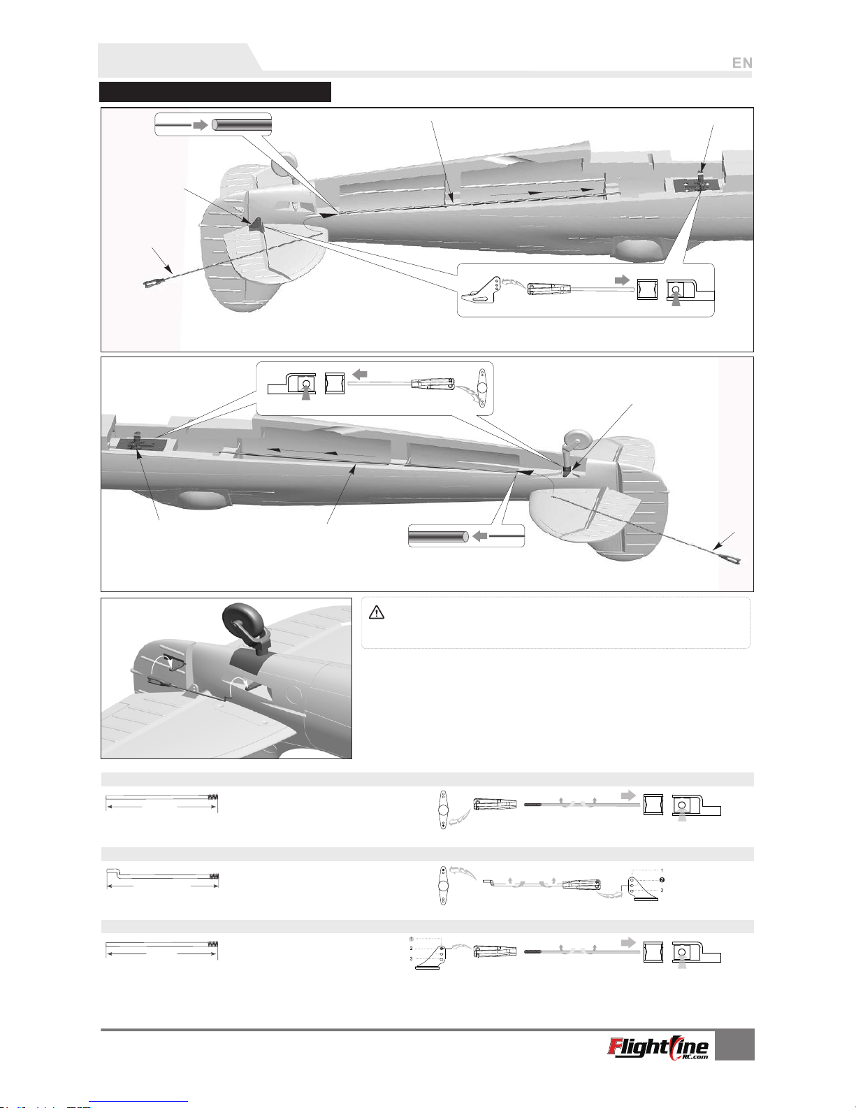
Install elevator/rudder pushrods
Note: When installing the rudder pushrod, make sure the tail gear is
centered, then install the rudder pushrod and adjust the plastic clevis to center
the rudder.
1. Use g lue to att ach the rudder ho rn on the ru dder.( as the
le ft photo s hown).
2. Use r udder p ushro d to conne ct the ta il gear st eering arm
an d r udder h orn.
Elevator p us hr od s iz e
Rudder pushr od s iz e
Elevator p us hr od m ou nt in g ho le
Rudder pushr od m ou nt in g ho le
Steering p us hr od s iz e Steering p us hr od m ou nt in g ho le
Pushrod diameter : Ø 1.2mm
Pushrod diameter : Ø 1.2mm
Pushrod diameter : Ø 1.2mm
Assembly
A
B
C
D
A
B
C
D
1. Insert one side of elevator pushrod A ,through plastic tube B, to
the servo arm C.
2.Snap the clevis of elevator pushrod to the rudder horn D.
1. Insert one side of rudder pushrod A ,through plastic tube B, to the servo arm C.
2.Snap the clevis of rudder pushrod to the rudder horn D.
6
Spitf ireMK.IX c
It emNo. :FLW 203
68m m
(2- 4/5")
545 mm
(21 -1/2" )
597 mm
(23 -1/2" )
Page 8
7
Spitf ireMK.IX c
It emNo. :FLW 203
A
B
C
D
E
F
G
H
-
-
-
-
-
-
-
-
(M3×3 mm )
(PB2. 3× 4m m)
(Ø65× 16 mm )
1
1
2
3
3
4
5
5
A
B
C
D
E
F
G
H
(Ø5.5 ×Ø 4. 2m m)
(M3×3 mm )
A
B
C
D
-
-
-
-
Screw
(KA2.6×12mm)
Landing gear strengthening p
late
Landing gear
Landing gear mount
Acce ssories
Main landing gear supporting rod
Wheel
Wheel locks
Jimi screw
Main gear door
Screw
Retract servo
Jimi screw
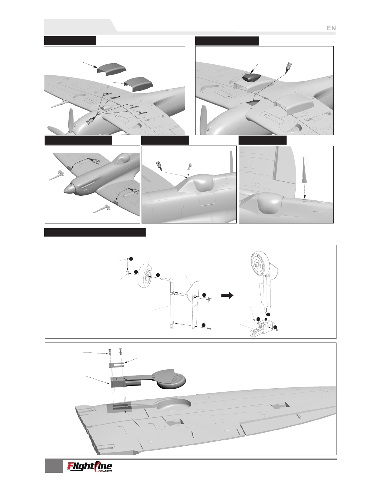
Main Landing Gear Assembly
Follow the diagram to assemble/disassemble the landing gear.
Assembly
A
B
C
D
A - Engi ne intake m anifo ld
A
A - Radia to r
B - Radia to r
B
Glue the Radiator A and B to the main wing surfaces, as
shown.
Use the glue to secure the engine intake manifold (A), and
affix it to the lower surface of the main wing of the shaded
area.
A
Use the glue to attach the Mirror , and
affix it to the transparent cockpit canopy.
Install mirr ors
Installmach ine guns
Glue the machine
guns to the main wing , as shown.
Install the intake scoop.
Install radi ators
Install ante nna
Page 9
1
2
3
4
5
6
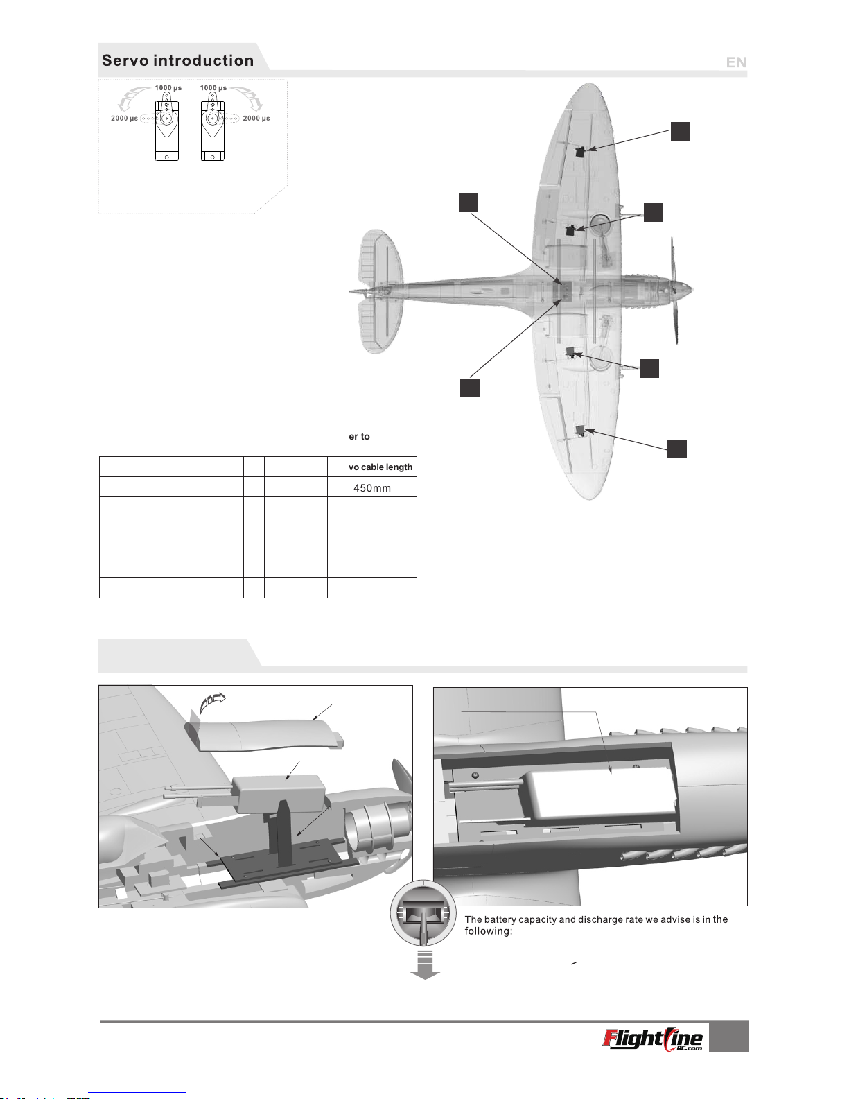
450mm
450mm
250mm
250mm
200mm
200mm
If you want to use another brand of servo, please refer to
the following list to choose correct size.
Posit iv e
Posit iv e
Rever se
Posit iv e
Posit iv e
Posit iv e
Servo installing position
No.
Pos./ Re v.
Servo cable length
Aileron servo (Left 9g plastic)
Aileron servo (Right 9g plastic)
Flap servo (Left 9g plasti c)
Flap servo (Right 9g plast ic)
Rudder servo (9g MG)
Elevator servo (9g MG)
Se rvo con nect ion
1.
2.
3.
Use a Y-cable to connect these two servos, then insert the cable end
into the aileron channel in the receiver.
Use a Y-cable to connect these two servos, and insert the cable end
into the flap channel in receiver.
Use a Y-cable to connect the left/right landing gear, and insert the
cable into the landing gear channel in receiver.
Before connecting the battery to the ESC, please power
up the transmitter and make sure the throttle stick is in the
lowest position.
Once the battery is connected and signal is confirmed,
make sure there is nothing in front of the airplane or within
the diameter of the propeller to avoid accidents and injury.
Lift up using the tape and
remove the battery
compartment hatch
Battery compartment hatch
Batte ry t ra y
Install the battery in the front of fuselage,
and use the Velcro strap to secure it.
Battery Ca bi n Si ze:2 05 ×8 0×45mm
4S 1 4. 8V 25 00mAh ~ 4 S 14 .8 V 400 0m Ah
Discharg e ra te o f C > 30 C
Velcro
Battery
1
3
2
4
5
6
8
Spitf ireMK.IX c
It emNo. :FLW 203
A servo or reversed servo is defined as follows:
When the servo input signal changes from 1000ųs
to 2000ųs, The servo arm rotates clockwise, its a
positive servo. If it rotates counter clockwise, its a
reversed servo
Installing a Battery
Page 10
9
Spitf ireMK.IX c
It emNo. :FLW 203
F
G
A
B
C
D
E
A
B
C
D
E
-
-
-
-
-
(HM2.5×10mm 4pcs)
(KM3×5mm 4pcs)
A
B
C
D
E
A
B
C
D
E
-
-
-
-
-
A
B
C
D
-
-
-
-
(PM3×8mm 1pcs)
(Ф14×1.5×Ф6.2mm)
A
B
C
D
E
F
G
-
-
-
-
-
-
-
(12×8)
A
B
C
D
-
-
-
-
(PWA3×8mm 4pcs)
(PA3×10mm 4pcs)
(Ф14×1.5×Ф6.2mm)
(PA2.3×16mm 8pcs)
(PM3×8mm 1pcs)
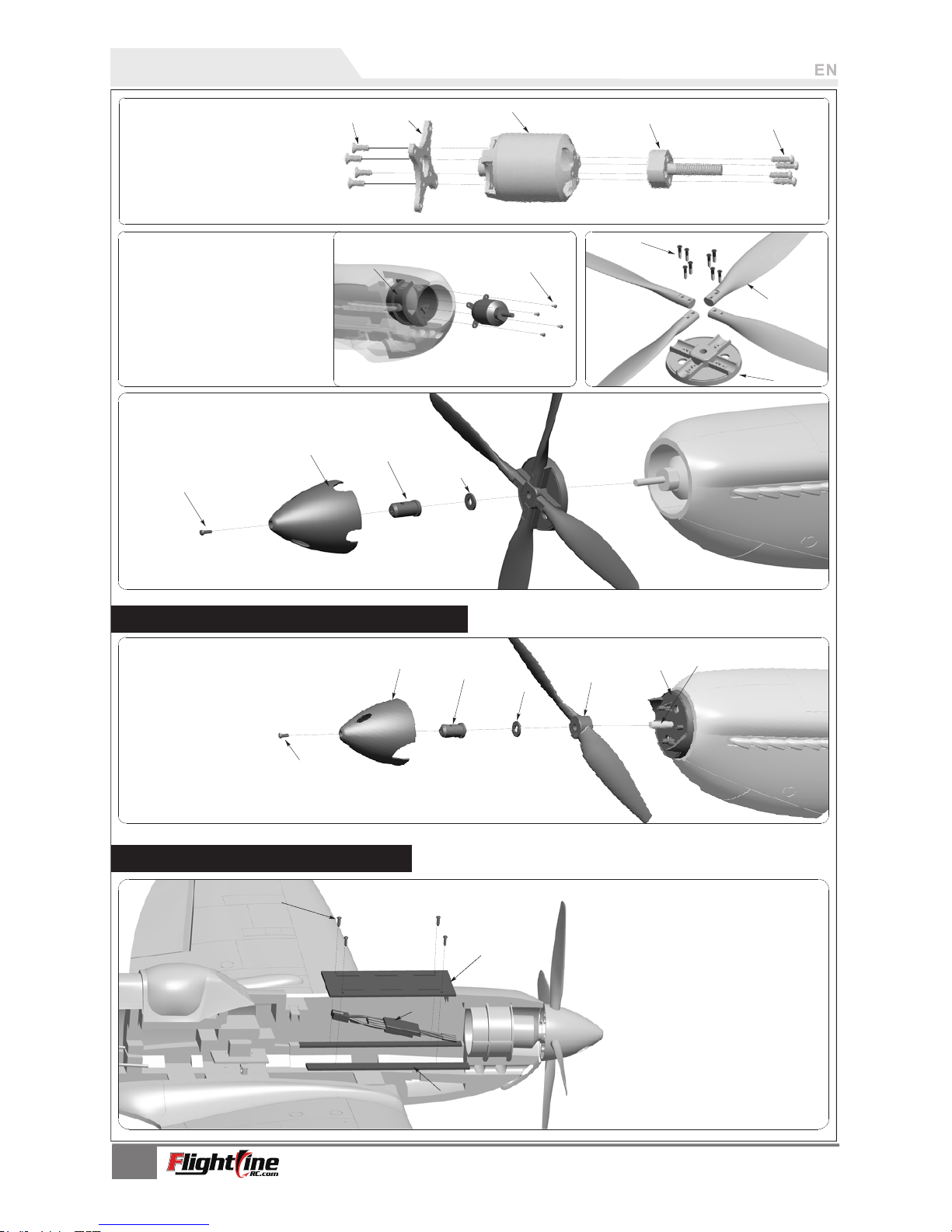
Put the ESC under the battery tray There are
specially designed ventilation ducts that will
cool the electric equipment effectively.
P
ower System Installation
Screw
Motor X-fi xe d ba se
3748-5 80 KV o ut -r un ne r motor
Propel le r fo ld er
Screw
Motor fixe d mo un t
Screw
Screw
Scale pr op el le r (1 2x 7, 4 -blade )
Scale pr op el le r fi xe d pl ate
Screw
Spinne r (s ca le 4 -b la de s pinner)
Propel le r fi xi ng b ol t
Was he r
Install 2-blade propelle r hig h pow er system
Screw
2-blade spinner
Propeller fixing bolt
Washer
2-blade propeller
2-blade propeller fixed plate
3648-880KV brushless motor
We prepared a 2-blade high power system for this
airplane, it can improve its power and flight speed, reduce the propeller
replacement cost! You can contact our distributor to purchase its high power
system.
Installing the ESC
Screw
Battery tr ay
ESC
Tra y ho ld er
A
B
C
D
E
A
B
C
D
A
B
C
D
Page 11
18.0
24.0
11.0
8.8
12.5
3.0
11.5
53.0
∅12.0
4-M3.0
47
2.3
5
25
4- M2.5
12 .5
Ø9 .0
Ø3 7. 5
Ø9 .6
Ø9 .0
Ø6 .0
4-Ø2.6
Ø2 0
4-Ø 3.2
4-Ø 3.2
43
.5
25
4- M2.5
12 .5
Ø9 .0
Ø3 6. 5
3748- 580KV /3648-88 0KV 3748- 580KV 3648- 880KV
ESC
Item No.
KV
Value
Volate
(V)
Curren t
(A)
Pull
(g)
Motor
Resist an ce
Weight
(g)
No Load
Curren t
580 RPM/V
14.8
41
2500
0.02
170
2.3A/1 0V
60A
MO13748 1
Propel le r
880 RPM/V
14.8
53
2600
0.02
165
2.3A/1 0V
60A
MO13648 4
4-Blade12×7
2-Blade12×8
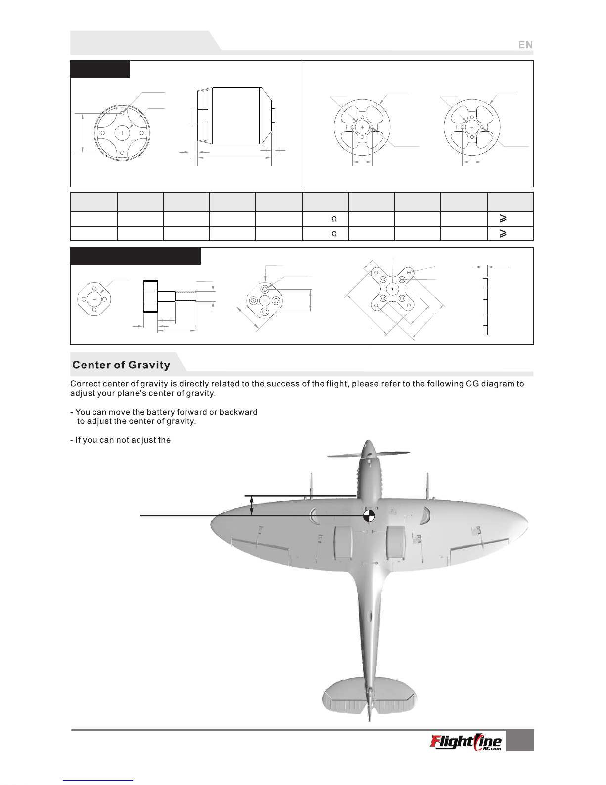
Motor Parameters
Unit: mm
Motor size
Motor shaft, X-fix ed ba se
Unit: mm
Unit: mm
73mm
(2-7/8")
10
Spitf ireMK.IX c
It emNo. :FLW 203
CG by moving the battery, you can also use an alternate material such as sticky
backed lead weight to achieve the CG.
Page 12
11
Spitf ireMK.IX c
It emNo. :FLW 203
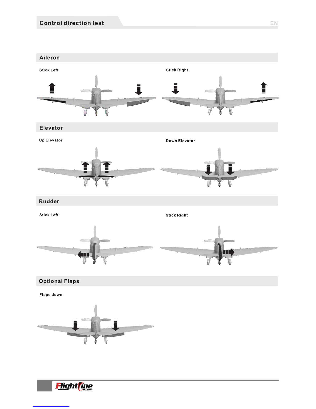
After the build is complete with the propeller removed, power up the radio and connect a fully charged battery to the
ESC. Use the radio to ensure proper control direction as shown in the diagrams below:
Page 13
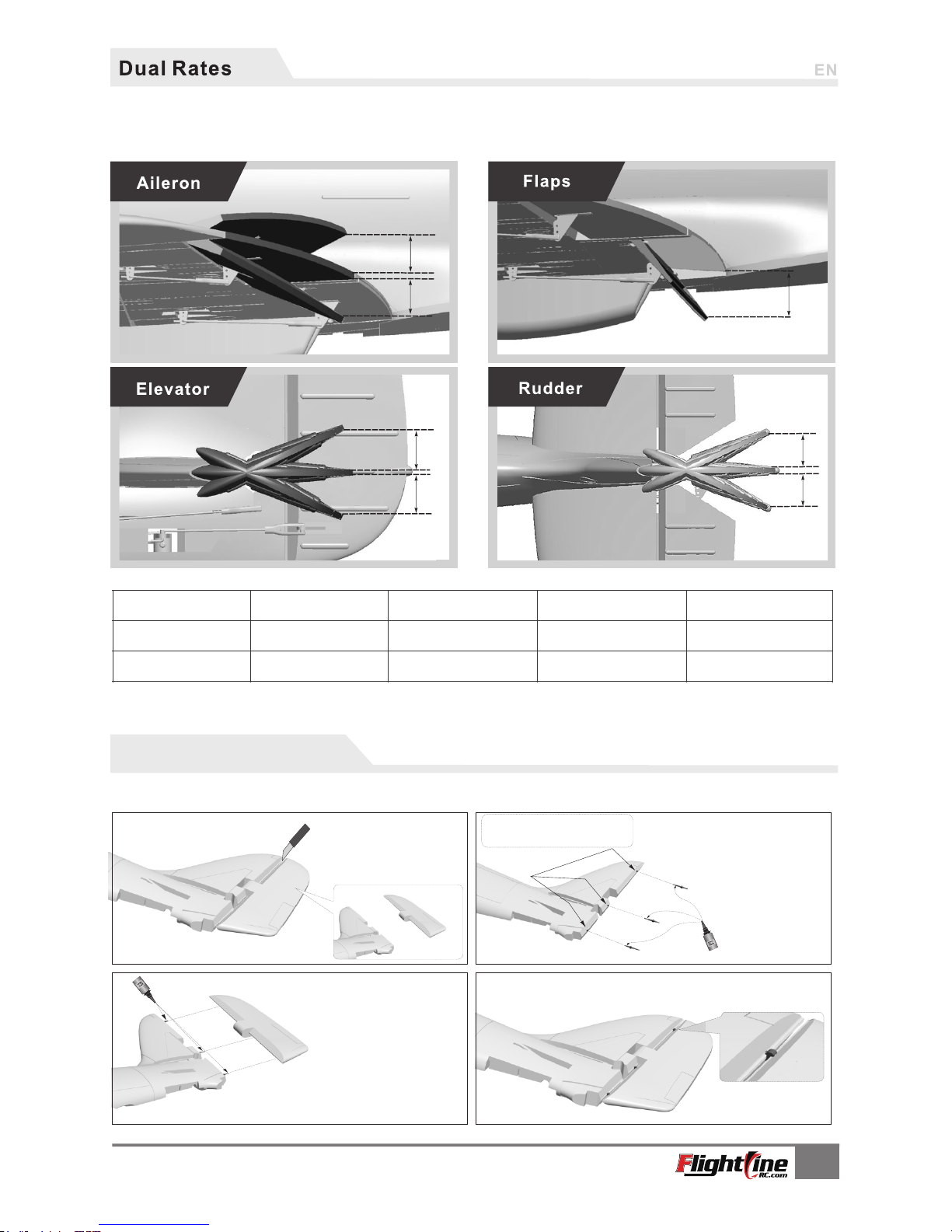
H1
H2
H1
H1
H2
H1
H2
H1/H2 18mm/ 18mm
H1/H2 18mm/18mm
H1/H2 13mm/13mm
H1/H2 22mm/22mm
H1/H2 15mm/15mm
H1 28mm
H1 15mm
H1/H2 28mm/ 28mm
Aileron
Elevator Rudder
Flaps
Low Ra te
High R ate
D/ R Rate:100% D/ R Rate:100% D/ R Rate:100%
D/ R Rate:65% D/ R Rate:65% D/ R Rate:65%
Select an appropriate location and
mark them . Make sure the three
points are in the middle of the
attachment point.
Installing Plastic Hinges
The control surfaces of this airplane use a no-hinge connection design. Although proven reliable, these type of hinges can be damaged due to
errors, causing the control surface to become loose or separate. Included with this kit is a set of plastic hinges if you wish to use them as an
alternate or for repair.
Step one
Use a knife to remove
the control surface
Step two
As shown in the diagram, choose
three attachment points, apply
glue to the long end of hinge, and
insert them into the three points.
Step three
As shown in the diagram,
apply glue to the other end of
the hinge and attach it to the
control surface.
12
Spitf ireMK.IX c
It emNo. :FLW 203
According to our test results, the following rates proved to be a good starting point. Low rates are good for initial
flights or less experienced pilots. Adjust rates to suit you own style.
Page 14

Build Notes
Hey guys!
I've taken the time to check out both the build video and the Flight Video by Ryan
Ramsay of Motion R/C as well as go through the posts on Hobby Squawk to try to
gather any build/ flight tips that may help you get through both successfully, with a
minimum of trouble.
First off, most people, including Ryan are using the recommended factory CG and
seem to be happy with it. The go to battery would seem to fall between 3600 and 4000
positioned all the way forward. When using a different battery, always check the
airplane out on a CG machine to ensure that the CG hasn't changed. Also, ensure that
your control surfaces are neutral. Being off even a bit will cause the plane to pitch or
roll.
When building the airplane, it is recommended that you skip steps one and two until
the wing is secured to the fuselage. Also, bind the receiver to the radio and set your
rudder and elevator neutral positions before installing the wing. It has been noted on
Hobby Squawk that the radiators and guns are side specific, so ensure that you have
the correct gun and radiator for the correct side before gluing. It's also recommended
that you use 30% expo for the first flight and then adjust to your personal taste.
For the build video, go to:
https://www.youtube.com/watch?v=FwdesiWtOSU&feature=youtu.be
and check out Hobby Squawk for the latest updates.
Happy Landings!
Dan
13
Page 15

Add.:FeiYi Building,face to Labor Bureau, Fumin Middle Road, Dalang Town,
Dongguan City,Guangdong Province, China
HK Freewing Model International Limited
R
东莞市飞翼电子 科技 有限 公司
香 港 飞 翼 模 型 国 际 有 限 公 司
地址: 广 东 省 东莞 市大 朗镇 富民 中路4 02- 408号飞翼 楼 四楼
Web: http://www.sz-freewing.com
Email:[email protected]
Tel: 86-769-82669669 Fax:86-769-82033233
Web: http://www.sz-freewing.com
Email:[email protected]
Tel: 86-769-82669669 Fax:86-769-82033233
Dongguan Freewing Electronic Technology Ltd
 Loading...