

Flightline FL-M1000A, FL-M1000E Instruction Manual
VHF AIR BAND TRANSCEIVER
FL-M1000A/FL-M1000E
Instruction Manual

2
ATTENTION
READ ME FIRST
FCC WARNING
Changes or modifications not expressly
approved by the party responsible for
compliance could void the user’s authority
to operate the equipment.
NOTICE:
This equipment has been tested and
found to comply with the limits for a Class
A digital device, pursuant to part 15 of
the FCC Rules. These limits are designed
to provide reasonable protection against
harmful interference when the equipment
is operated in a commercial environment.
This equipment generates, uses and
can radiate radio frequency energy and,
if not installed and used in accordance
with the instructions, may cause harmful
interference to radio communications.
Operation of this equipment in a
residential area is likely to cause harmful
interference in which case the user will be
required to correct the interference at his
own expense.
• Properly shielded a grounded cables
and connectors must be used for
connection to host computer and /
or peripherals in order to meet FCC
emission limits. (AC adaptor) with ferrite
core must be used for RF interference
suppression.
Notes to the Installer /
User.
• This is a 13.8-volt or 26.4-volt DC radio,
voltages greater than 33 volts DC or AC
voltage will severely damage it.
• When making adjustments to the
transmitter, ensure that you are not on
an occupied channel.
• Do not transmit on 121.500MHz, as this
is the international distress frequency.
• Do not transmit into an unterminated
antenna line as a suitable antenna must
be connected. Transmitting without
being connected to an antenna may
damage the radio.
• Ensure that the supply voltage is
regulated and does not fall below 11.7
volts DC or exceed 31 volts DC.
• The transceiver is not waterproof. Do
not allow it to get wet.
• Speaker impedance must be either 4 or
8 ohms (4 ohms preferred) at 10 watts.
• Use of electret microphones highly
recommended.
About this document.
Due to our policy of continuous
improvement to our products and
services, technical specifications and
claims are correct at time of going to
printing, however they are subject to
change without notice.
Flightline does not accept liability for any
error or omission.
This manual remains the copyright of
Flightline.

3
CONTENTS
INTRODUCTION ......................................4
Introduction ...............................................4
Part names and functions ........................5
MP-1000 microphone ...............................7
Display ......................................................8
Recalling the Pri channel ........................10
BASIC OPERATION ..............................
11
Basic usage ............................................11
Turning the power on or off ....................12
Adjusting the audio volume ....................12
Adjusting the squelch level .....................13
Changing the channel .............................14
Change mHz/kHz for variable
frequency .............................................14
Dimmer ....................................................15
Transmitting ............................................15
MEMORY AND SCAN OPERATION .....
16
Scanning the VFO frequencies ...............16
Scanning the memory.............................16
Scanning with the priority channel .........17
Priority watch ..........................................18
Other memory operations ......................19
MEMORY OPERATIONS ......................
20
Memorizing a frequency .........................20
Switching the VFO and
memory mode .....................................20
Erasing a memory ...................................21
Setting the priority memory ....................21
Recalling the priority channel ................ 22
Naming the memory channel
(Memory tag) .......................................23
Setting the lockout memory channel .....24
ADVANCED OPERATION
..................... 25
Emergency call .......................................25
Changing the settings .............................25
Changing the each settings ....................26
APPENDIX ............................................. 27
Connecting ..............................................27
Mounting ................................................ 29
Optional headset adapter ...................... 30
Specifications ........................................ 32
Frequency list (Example of frequency
versus display when using 8.33 Khz
step) .................................................... 33
Supplied accessories ............................ 34

4
INTRODUCTION
Introduction
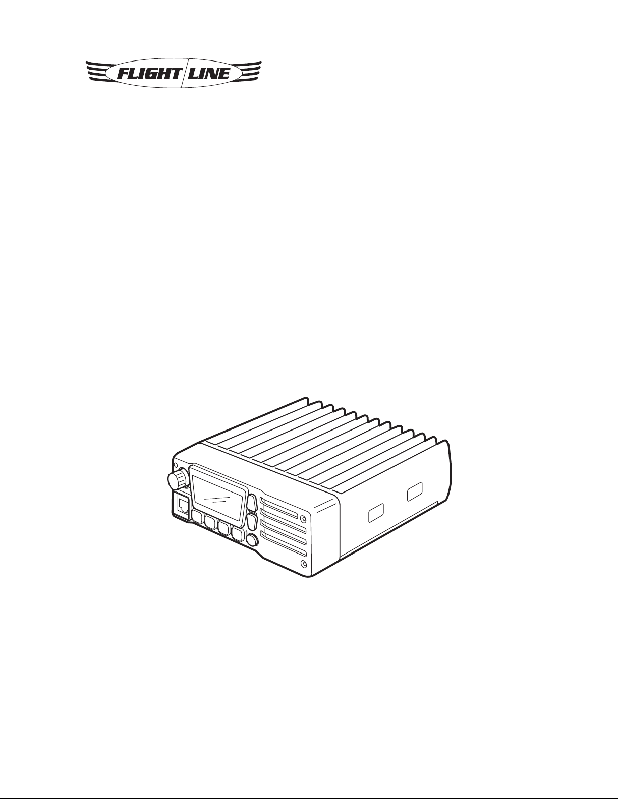
Thank you for purchasing this quality
product from Flightline.
This transceiver has been designed and
manufactured in Japan. This is the best
product for vehicle working in the Airport.
Ease of operation was another primary
achievement.
Please follow this manual closely to
ensure optimum performance, we do
hope you have many hours of trouble free
communication.
Installation instructions
This manual contains all of the necessary
instructions for installation and operation.
After installation please keep this manual
in a safe place for future reference.
Installation considerations
As with all air Air Band radios, successful
communications start with the installation.
After unpacking the transceiver verify all
parts against the parts list. The Display
provides a 30-degrees field of view
from right and left, and from upper side.
However from the down side, it is out of
guarantee.
Please be careful when install this
product.
The use of aviation quality shielded cable
is recommended at all times.
Avoid running or wrapping other wires
around the antenna lead and keep lengths
as short as reasonably possible. Ensure
that the radio is not exposed to direct rain
or moisture (we do not accept liability for
water damage).
Make sure the transceiver is connected
to a 11.7-16.8 volt or 23-31 volt battery
system.
Do not use AC volts from a Rotax lighting
coil.
About this product
This product is Air Band Land Mobile
Radio designed for vehicle, not for
Aircraft.
The radio can be operated with Hand
Microphone or Headset. You can choose
audio output from External Speaker and/
or Headphone.
The radio has various built-in Scan
function.
5
INTRODUCTION
Part Names and Functions
Front panel
kHz
FL-M1000
PWR
SQL
V/M
SCAN
PRI
: @ ;.
8 2 > B =
q
TX/RX indicator
• Indicate Red in transmission, Green in
Receiving.
w
Rotary Encoder
• Change the operating Frequency or
Memory Channel.
• Turning this Encoder while pausing
scan resumes the Scan mode.
• LCD Backlight will be ON by short
press.
• Available to change the tuning range by
Long Press.
e
Volume button
• The audio volume will be up or down.
r
Internal Speaker
• Internal Speaker.
• The audio output is available to change
to Headphone.
t
PWR button
• Short press: indicates voltage of power
source.
• Long press: turn the radio ON/OFF.
y
SQL button
• Available to change the Squelch setting.
u
PRI button
• Short Press: recall the Priority Channel.
• Long Press: recall the Emergency
Channel..
i
SCAN button
• Short Press: start SCAN function.
• Long Press: start Dual Watch function.
o
V/M button
• Short Press: switch between Memory
mode and VFO mode.
• Long Press: Add memory current
channel.

6
INTRODUCTION
!0
Microphone connecter
• Connect the supplied Microphone
(do not connect other microphone to
prevent trouble)
7
INTRODUCTION
MP-1000 Microphone
=
;
@
B
.
:
q
Volume UP/DOWN
• Decrease audio volume by press the v
button, and increase by c button
w
Monitor Button
• Press the button makes the radio in
monitor mode.
e
PTT (Push To Talk)
• Press the button makes the radio to
transmit mode, and release to receive
mode.
r
Microphone
• Speak into the circled area when
talking.
Note:
There is a microphone element in the
circled area. The sound becomes
unclear if it doesn’t speak toward the
circled part.
t
Busy Indicator (Green)
• It will become Green while somebody is
talking, or squelch is open.
y
Hanger
• It is a metal hanger to hook the
microphone.
8
INTRODUCTION
Display
> 2 8
=;.@:
B
q
Low battery indicator
• The “L” will indicate when the voltage of
power source becomes less than 11.7
Volt.
w
Busy indicator
• The Busy icon will indicate when
receiving.
e
Emergency indicator
• The “EMG” icon will indicate when
recall the Emergency channel.
r
Priority Watch indicator
• The “P” icon will indicate when the
radio is in Priority Scan or Priority watch
mode.
t
Scan indicator
• The “SCAN” icon will indicate when the
radio is in SCAN mode.
y
Memory indicator
• The “MR” icon will indicate when the
radio is displaying a memory channel.
u
LOCKOUT indicator
• The “LOCKOUT” icon will indicate when
the channel is not in the SCAN LIST.
i
Setting mode indicator
• The “SET” icon will indicate when the
radio is in SETTING mode.
o
Volume level indicator
• It indicates the Audio Volume Level.
!0
Memory number indicator
• It shows memory number or “Pr” as
priority.
!1
Main indicator
• It shows frequency and/or setting etc..
!2
Decimal point indicator
• It indicates “dot” at decimal point.
9
INTRODUCTION
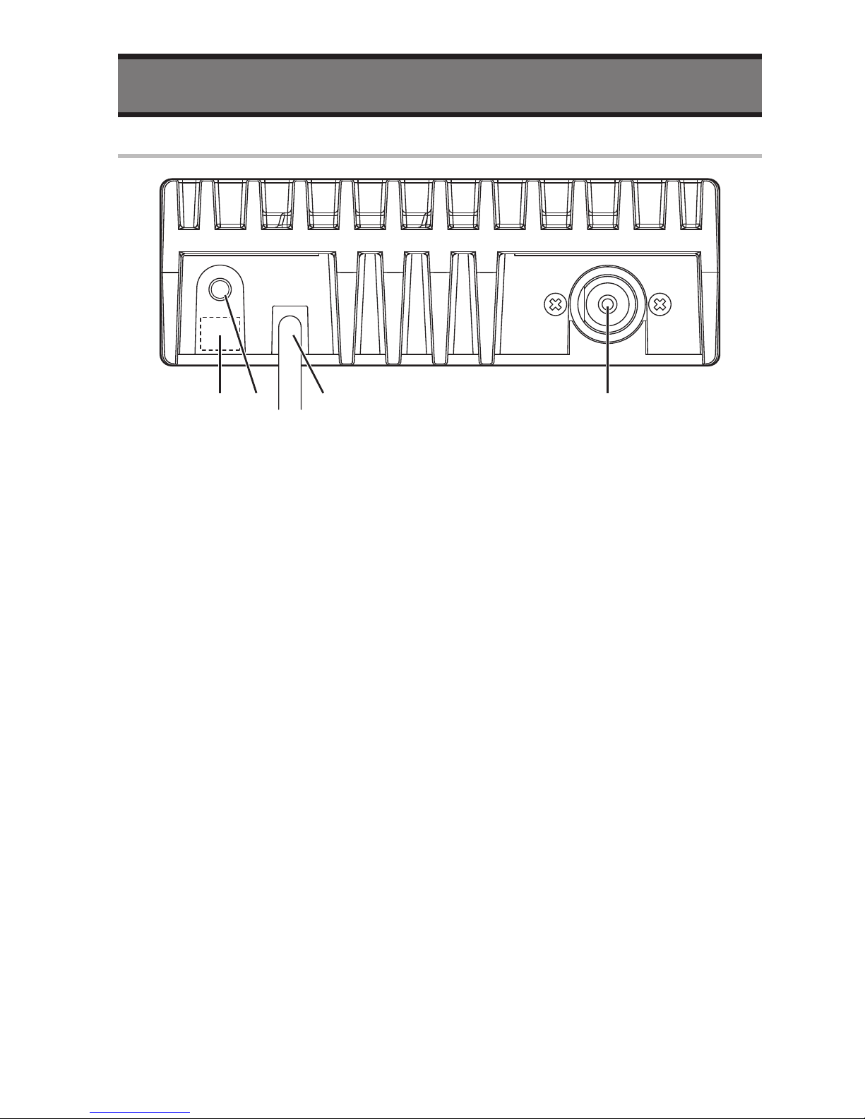
Rear panel
:@; .
q
Antenna Connector
• Connect an Antenna with PL-259 type
(50 ohms, SWR: less than 3.0)
w
Power Cable
• Connect a Battery (12 V or 24 V). Do not
connect the other type.
e
External Speaker Jack
• Connect a Speaker with more than 10 W,
8 ohms.
r
Optional Jack
• Connect a Headset (supplied by 3rd
party)
Please contact your dealer if you have any
question.

10
INTRODUCTION
Recalling the Pri Channel
You can recall a Priority Channel by
pressing the PRI button when the radio
is in VFO mode or in Memory Channel
mode.
1
Press the PRI button
• The channel will be changed to
Priority Channel and the “Pr” will be
displayed instead of memory channel
number.
2
Press the PRI button again to return
to previous channel
11
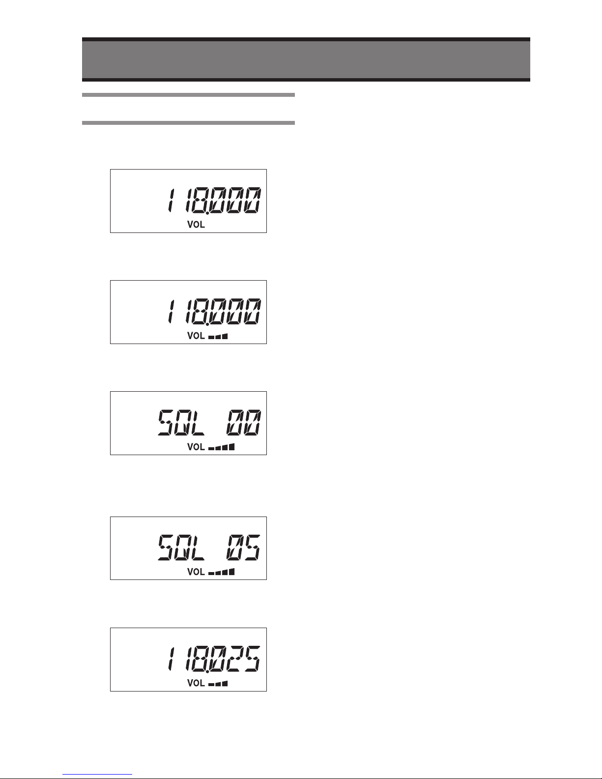
BASIC OPERATION
Basic Usage
1
Press the PWR button more than
two seconds.
2
Adjust the audio level by Volume
button.
3
Press the SQL button to adjust the
Squelch level.
4
Turn the Rotary Knob slowly
direction to clockwise until noise
disappear.
5
Press the SQL button to save and
exit the adjustment.
6
Turn the Rotary Knob to select
desired frequency.
• The TX/RX Indicator will become
Green if the radio receives a signal.
7
Wait a signal from transmitting your
partner.
8
Monitor the frequency is not busy
before transmission.
9
Hold the microphone about 1 to
3cm away from your mouth.
10
Speak slowly and clearly into the
microphone with press and hold
the PTT switch.
• The TX/RX Indicator on the radio will
become Red while transmitting.
 Loading...