

FLIGHT LINE FL-760 series Installation & Operation Manual
Page 0
FL
FLFL
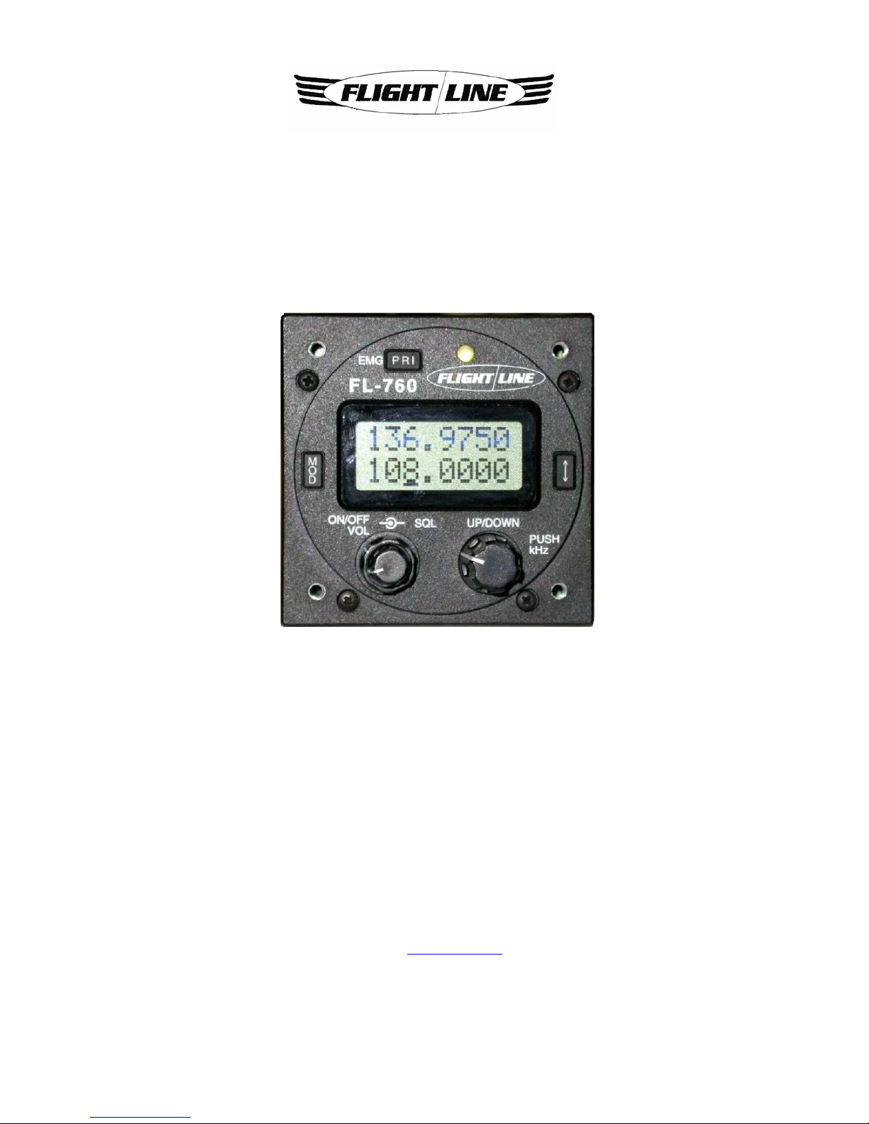
FL----760
760760
760
VHF
VHFVHF
VHF Aircraft
AircraftAircraft
Aircraft Transceiver
TransceiverTransceiver
Transceiver
Installation / Operation
Installation / OperationInstallation / Operation
Installation / Operations Manual
s Manuals Manual
s Manual
FL
FLFL
FL----760 series
760 series760 series
760 series
Flightline
FlightlineFlightline
Flightline
12830 E. Mirabeau Parkway
12830 E. Mirabeau Parkway 12830 E. Mirabeau Parkway
12830 E. Mirabeau Parkway
Spokane Valley, WA 99216
Spokane Valley, WA 99216Spokane Valley, WA 99216
Spokane Valley, WA 99216
Toll free
Toll freeToll free
Toll free tel.
tel. tel.
tel.: 1
: 1: 1
: 1----800
800800
800----235
235235
235----3300
33003300
3300
Toll free fax
Toll free faxToll free fax
Toll free fax: 1
: 1: 1
: 1----800
800800
800----828
828828
828----0623
06230623
0623
http://
http:// http://
http://
www.edmo.com
www.edmo.comwww.edmo.com
www.edmo.com
VHF AM Aircraft R
VHF AM Aircraft RVHF AM Aircraft R
VHF AM Aircraft Raaaadio
diodio
dio
FCC ID:
FCC ID: FCC ID:
FCC ID: VOSFL760 A
VOSFL760 AVOSFL760 A
VOSFL760 A

Page 1
AT TENTION
AT TE NTION AT TE NTION
AT TE NTION
READ ME FIRST
READ ME FIRSTREAD ME FIRST
READ ME FIRST
FCC WARNING
FCC WARNING FCC WARNING
FCC WARNING
Changes or modifications not expressly approved by the party responsible for compliance could void the
user’s authority to operate the equipment.
NOTICE
This equipment has been tested and found to comply with the limits for a Class A digital device,
pursuant to part 15 of the FCC Rules. These limits are designed to provide reasonable protection
against harmful interference when the equipment is operated in a commercial environment.
This equipment generates, uses and can radiate radio frequency energy and, if not installed and used
in accordance with the instructions, may cause harmful interference to radio communications.
Operation of this equipment in a residential area is likely to cause harmful interference in which case
the user will be required to correct the interference at his own expense.
Properly shielded a grounded cables and connectors must be used for connection to host computer and /
or peripherals in order to meet FCC emission limits.
(AC adaptor) with ferrite core must be used for RF interference suppression.
The Flight
The FlightThe Flight
The Flightline transceiver has been factory preset and in most cases the transmitted audio should
line transceiver has been factory preset and in most cases the transmitted audio shouldline transceiver has been factory preset and in most cases the transmitted audio should
line transceiver has been factory preset and in most cases the transmitted audio should
be correct. A 15 pin connector is supplied for connection to the electrical sy
be correct. A 15 pin connector is supplied for connection to the electrical sybe correct. A 15 pin connector is supplied for connection to the electrical sy
be correct. A 15 pin connector is supplied for connection to the electrical system and
stem andstem and
stem and
microphone/speaker.
microphone/speaker.microphone/speaker.
microphone/speaker.
Notes
NotesNotes
Notes to the installer / user.
to the installer / user. to the installer / user.
to the installer / user.
・ This is a 14-volt or 28-volt DC radio, voltages greater than 33 volts DC or AC voltage will
severely damage it.
・ When making adjustments to the transmitter, ensure that you are not on an occupied channel.
・ Do not transmit on 121.500MHz, as this is the international distress frequency.
・ Do not transmit into an unterminated antenna line as a suitable antenna must be connected.
Transmitting without being connected to an antenna may damage the radio.
・ Ensure that the supply voltage is regulated and does not fall below 11.7 volts DC or exceed 31
volts DC.
・ The transceiver is not waterproof. Do not allow it to get wet.
・ Speaker impedance must be either 4 or 8 ohms (4 ohms preferred) at 5 watts.
・ Use of electret microphones highly recommended.
About this document.
Due to our policy of continuous improvement to our products and services, technical specifications
and claims are correct at time of going to printing, however they are subject to change without
notice.
Flightline does not accept liability for any error or omission.
This manual remains the copyright of Flightline.

Page 2
TABLE OF CONTENTS
TABLE OF CONTENTSTABLE OF CONTENTS
TABLE OF CONTENTS
SECTION Page
ATTEN TI ON
ATTEN TI ONATTE NTION
ATTEN TI ON---- READ ME FIRST
READ ME F IRST READ ME F IRST
READ ME F IRST …………… …………
……………… ……………… …………… …
……………… ………………… ………………
……………… ………………………… …………
……………… ………… ....1111
TA BL E O F CONT ENTS
TA BL E O F CONT ENTSTA BL E O F CONT ENTS
TA BL E O F CONT ENTS… …… …………… …… …… …… …… …… ……………
…… …… …… ……… …… …… …… …… …… ……………… …… …… ……… …… …… …… …… …… …………
…… …… …… ……… …… …… …… …… …… …………2222
1 IN TRO DU CTI ON
1 IN TRO DU CTI ON1 IN TRO DU CTION
1 IN TRO DU CTI ON ……… …………… …… ……… …………… …………… …
…………… …………… …… ……… …………… …… ………………… …………… …… ……… …………… …… ……
…………… …………… …… ……… …………… …… …….. 3
.. 3.. 3
.. 3
2 INST
2 INST2 INST
2 INSTAAAALLATION IN STRUCTION S
LLATION INSTRUCTIONSLLATION INSTRUCTIONS
LLATION INSTRUCTIONS ……………………………………………
…………………………………………………………………………………………
……………………………………………. 3
. 3. 3
. 3
3 INST
3 INST3 INST
3 INSTAAAALLATION CONSIDERATIONS
LLATION CONSI DERATIONSLLATION CONSI DERATIONS
LLATION CONSI DERATIONS …………………………………………
………………………………… ………………………………………… ………
………………………………… ……….3
.3.3
.3
4 GENE RAL
4 GENE RAL4 GENE RAL
4 GENE RAL …… …… …… …… …… …… ……………………… …… …… …… …
…… …… …… …… …… …… …… …… …… ………………… …… ……… …… …… …… …… …… …… …… …… ………………… …… …
…… …… …… …… …… …… …… …… …… ………………… …… … .4
.4.4
.4
4.1 Sailplanes
4.1 Sailplanes 4.1 Sailplanes
4.1 Sailplanes
………………………………………………………………………………………………
…………………………………………………………………………………………………………………………………………………………………………
……………………………………………………………………………………
4444
4.2 Ultralight
4.2 Ultralight4.2 Ultralight
4.2 Ultralightssss ………….
. .
.
………
………………
…………………………………………………………………………………
……………………………………………………………………………………………………………………………………………………
…………………………………………………………………………
4444
4.3
4.34.3
4.3 Microlight / Homebuilt / G.A.
Microlight / Homebuilt / G.A. Microlight / Homebuilt / G.A.
Microlight / Homebuilt / G.A. ……………………………………………………
…………………………………………………………………………………………………………
……………………………………………………..
....
..4444
5 BEFORE BEGINNING
5 BEFORE BEGINNING5 BEFORE BEGINNING
5 BEFORE BEGINNING INST
INST INST
INSTAAAALLATION
LLATIONLLATION
LLATION………………………………………
………………………………………………………………………………
………………………………………..
....
..…………....……
…………
……5555
5.1 Installation parts
5.1 Installation parts 5.1 Installation parts
5.1 Installation parts identification..
identification..identification..
identification..………………………
………………………………………………
………………………..
....
..…………………………………
………………………………………………
………………………....
........
....5555
5.2 Transceiver installation and removal
5.2 Transceiver installation and removal5.2 Transceiver installation and removal
5.2 Transceiver installation and removal ……
…………
……..
....
..………………………………………
………………………………………………………………………………
………………………………………...
......
... 5555
5.3
5.3 5.3
5.3 General
GeneralGeneral
General..
....
..……………………………………………………………………………
…………………………………………………………………………………………………………………………………………………………
……………………………………………………………………………..
....
..……
…………
……5555
5.4 Pin connections
5.4 Pin connections5.4 Pin connections
5.4 Pin connections ...
... ...
...……………………………………………………………
…………………………………………………………………………………………………………………………
……………………………………………………………....…………
……………………
………….
. .
. 5555
5.5 Mechanical installation
5.5 Mechanical installation5.5 Mechanical installation
5.5 Mechanical installation ...
... ...
...……………………………………………………………
…………………………………………………………………………………………………………………………
……………………………………………………………....…………5555
5.6
5.6 5.6
5.6 El
ElEl
Electrical installation
ectrical installationectrical installation
ectrical installation ……………………………………………………………………
…………………………………………………………………………………………………………………………………………
……………………………………………………………………6666
5.7 Antenna
5.7 Antenna5.7 Antenna
5.7 Antenna iiiinstallation..
nstallation.. nstallation..
nstallation..
………..............................................................
………..............................................................………..............................................................
………..........................................................................................
........................................................
............................
7777
5.
5.5.
5.8888 Tuning
Tuning Tuning
Tuning ………………………………………………………………………………………………
………………………………………………………………………………………………………………………………………………………………………………………………
………………………………………………………………………………………………....
7777
5.
5.5.
5.9999 On air testing
On air testing On air testing
On air testing …………………………………
……………………………………………………………………
………………………………………………………………………………………
…………………………………………………………………………………………………………
……………………………………………………
7777
6 OPERATION OF EQUIPMENT
6 OPERATION OF EQUIPMENT6 OPERATION OF EQUIPMENT
6 OPERATION OF EQUIPMENT ……………………………………………………………
…………………………………………………………………………………………………………………………
……………………………………………………………8888
6.1 General
6.1 General6.1 General
6.1 General …………………………………………………………………………………
……………………………………………………………………………………………………………………………………………………………………
…………………………………………………………………………………..
....
.....8
...8...8
...8
6.2 Control d
6.2 Control d6.2 Control d
6.2 Control description
escriptionescription
escription …………………………………………………………………
……………………………………………………………………………………………………………………………………
…………………………………………………………………..
....
..…………8888
6.3 Memory programming
6.3 Memory programming6.3 Memory programming
6.3 Memory programming ……………………………………
…………………………………………………………………………
………………………………………………………………………
………………………………………………
…………………………………10
1010
10
6.4 Memory delete
6.4 Memory delete6.4 Memory delete
6.4 Memory delete ……………………………
…………………………………………………………
…………………………………………………………………………
…………………………………………………………………………………………
……………………………………………. 10
. 10. 10
. 10
6.5 Operation of intercom
6.5 Operation of intercom6.5 Operation of intercom
6.5 Operation of intercom ……………………………………………………………
…………………………………………………………………………………………………………………………
……………………………………………………………. 10
. 10. 10
. 10
6.6 User setting
6.6 User setting6.6 User setting
6.6 User setting …………………………………………………………………………
……………………………………………………………………………………………………………………………………………………
…………………………………………………………………………. 10
. 10. 10
. 10
6.7
6.7 6.7
6.7 Music
MusicMusic
Music input
input input
input ……
…………
……
……………………………………………………………………
…………………………………………………………………………………………………………………………………………
………………………………………………………………………………..
....
..
11111111
7 SPECIFICATIONS
7 SPECIFICATIONS7 SPECIFICATIONS
7 SPECIFICATIONS …………………………………………………………………………
……………………………………………………………………………………………………………………………………………………
………………………………………………………………………… 12
12 12
12
8 HELPFUL HINTS
8 HELPFUL HINTS8 HELPFUL HINTS
8 HELPFUL HINTS ……………………………………
…………………………………………………………………………
…………………………………………………………………………
…………………………………………………………………………
……………………………………. 13
. 13. 13
. 13
WARR
WARRWARR
WARRANTY
ANTYANTY
ANTY
EEEEXTERNAL CONNECTIONS
XTERNAL CONNECTIONSXTERNAL CONNECTIONS
XTERNAL CONNECTIONS

Page 3
1 INTRODUCTION
1 INTRODUCTION1 INTRODUCTION
1 INTRODUCTION
Thank you for purchasing this quality product from Flightline.
This transceiver has been designed and manufactured in Japan specifically for Ultralights,
Gliders and General Aviation Aircraft and Helicopters with size and power consumption as the
main considerations. Ease of operation was another primary achievement.
Please follow this manual closely to ensure optimum performance, we do hope you have many
hours of trouble free communication and safe flying.
2 INST
2 INST2 INST
2 INSTAAAALLATION INSTRUCTIONS
LLATION INSTRUCTIONSLLATION INSTRUCTIONS
LLATION INSTRUCTIONS
This manual contains all of the necessary instructions for installation and operation. After
installation please keep this manual in a safe place for future reference.
3 INST
3 INST3 INST
3 INSTAAAALLATION CONSIDERATIONS
LLATION CONSIDERATIONSLLATION CONSIDERATIONS
LLATION CONSIDERATIONS
As with all aircraft radios, successful communications start with the installation. After unpacking
the transceiver verify all parts against the parts list. Select a suitable mounting area within a
maximum 30 degree viewing angle and select a suitable location for operation of ancillary controls,
backlight, intercom etc.
The use of aviation quality shielded cable is recommended at all times.
Avoid running or wrapping other wires around the antenna lead and keep lengths as short as
reasonably possible. Ensure that the radio is not exposed to direct rain or moisture (we do not
accept liability for water damage).
Make sure the transceiver is connected to a 11.7-16.8 volt or 23-33 volt battery system.
Do not use AC volts from a Rotax lighting coil.

Page 4
4 GENERAL
4 GENERAL4 GENERAL
4 GENERAL
The following section is a guide for individual types of aircraft installations.
4.1 Sailplanes
4.1 Sailplanes4.1 Sailplanes
4.1 Sailplanes
Due to the inherent space restriction on most glider instrument panels the FL-760’s 57-mm front
panel makes it an excellent choice for confined spaces. Generally the radio is mounted at the
bottom of the panel with essential instruments at the top. Location of the ancillary switches
should be convenient to the pilot.
The Press to Talk (PTT) can be a normally open push-button located on the control column or a
handheld microphone.
Speakers are normally located at the rear of the pilot’s head.
If not using a handheld microphone, then a boom mike with an electret microphone is preferred.
If this radio is to be installed in a motor glider then ensure that the ignition leads are shielded.
This will reduce ignition noise considerably. The FL-760 has noise limiting circuitry incorporated
and works well in most cases but two stroke interference can be difficult to suppress.
4.2 Ultralight
4.2 Ultralight4.2 Ultralight
4.2 Ultralight
Most ultralights like sailplanes suffer from space restriction. Locate the transceiver with a good
viewing angle. Ensure that it is protected from rain (No liability is accepted for water damage).
Use shielded aviation quality wire for the headphones, microphone, and speaker.
As nearly all Ultralights use two-stroke engines ignition noise can be a problem. Again ensure
that all engine high voltage cabling is shielded and grounded. There is almost certainly some
background ignition noise with these engines, however, the FL-760 noise limiter will eliminate
nearly all of the noise (except for levels around 5
uV).
In tandem or side by side seating, use of the intercom provided will work well providing you switch
it on. The intercom uses the side-tone feature of the radio and therefore may pick-up some
ambient noise.
Another feature is the fitting of the external memory toggle switch which when fitted (normally on
the control column) allows the pilot to scroll through the memory channels and select scan without
reaching for the main channel controls on the radio. This is particularly useful for the rear pilot or
instructor in tandem Ultralights or for Helicopter/Gyroplane pilots.
4.3 Microlight / Home built / G.A.
4.3 Microlight / Home built / G.A.4.3 Microlight / Home built / G.A.
4.3 Microlight / Home built / G.A.
In general the same as for ultralights with particular care taken for ignition screening and
exposure to rain.
 Loading...