

Flightline B-24 LIBERATOR User Manual
EN
1~11
中
12~22
WINGSPAN:2000MM(78.7in.)
LENGTH:1230MM(48.4in.)
WEIGHT:2190G (W/O BATTERY)
U S E R M A N UAL
B-24 LIBERATOR
1
B-24 LIBERATO R
Ite n No.:
Th e fa med B-24 L ibera tor is o ne o f the most rec ogniz able WWII air craft of a ll t ime. Serv ing in every t heate r of
that glo bal confl ict, the B-24 fought to bring its br ave crews hom e th rough uni magin able dang er. With humi lity and
reve rence , Flig htLin eRC and M otion RC are pr oud to intro duce the world ’s first foam ele ctric PNP B-24 Liberator, in
reme mbran ce of the c rews wh o gave th e ultim ate sac rific e and tho se who ca rry on it s memor y.
Th e F light LineR C B -24 i s a pprox imate ly 1/10 scale , w ith a 2000mm win gspan an d 1 230mm leng th. Cons truct ed
from EPO fo am and reinf orced with integr ated alumin um, ca rbon, and plastic structu res, the B-2 4 deli vers the
ulti mate a ll aroun d experi ence for pilot s s eekin g the ultim ate foam PNP bomber replica . A ma gneti c nose sectio n
allo ws owners to swa p betw een two B- 24 var iants , the -D (” Green house ” nose), a nd the -J ( ”Emer son tu rret” nose) .
The Upper Turr et on both variant s and the Nose Turr et on the -J variant can be panne d with an o ption al servo.
Stee rable t iller s are pre -inst alled , inclu ding sp ecial p rovis ions to f it FPV ca meras i nside .
The Fli ghtLi neRC B-24 us es fou r 3530 -860K V brushl ess outr unner mo tors and fo ur 30A ESC s. A q uick
disc onnec t rib bon wire h arnes s con solid ates wirin g int o a centra l cir cuit board in the fuselage. T he re comme nded
pair of 4s 14.8V 2800-4 000mA h lip o bat terie s 2pcs can power the aircraft in exc ess of 110kph/70mph, for 4-10
minu tes base d on a pilot ’s th rottl e management. The out board mo tor pair and inbo ard moto r pair ar e run from
sepa rate fligh t batte ries, allowi ng for power ed la nding s in th e event of one b atter y fai ling. A 7 0mm tall nos e whe el
and 85mm tail main wheel s pro vide stabl e ope ratio n grass runways, and o ption al su spens ion s truts are av ailab le.
Asse mbly is c ompri sed of on ly 12 scr ews and g luing o n exter nal det ails su ch as ant ennas .
1.Th is is not a t oy! Ope rater s hould h ave a cer tain experienc e, begi nners s hould o perat e under t he guid ance of
prof essio nal pla yers.
2.Be fore in stall , pleas e read th rough t he instruction s caref ully an d opera te stri ctly un der ins truct ions.
3.Ca use of wr ong ope ratio n,Fre ewing a nd its vendors will not be he ld resp onsib le for an y losse s.
4.Mo del pla nes’ player s must be o n the age o f 14 year s old.
5.Th is plan e used th e EPO mat erial w ith sur face spray paint , don’ t use chem ical to c lean, o therw ise it wi ll dama ge.
6.You shoul d be care ful to av oid flyi ng in are as such a s public places,high- volta ge-in tensi ve area s,nea r the hig hway,
near t he airp ort or an y other p lace wh ere law s and regulation clearl y prohi bit.
7.You canno t fly in bad w eathe r condi tions s uch as th understorms, snows ....
8.Mo del pla ne’s batt ery, don’t a llowe d to put in e verywhere. Sto rage mu st ensu re that t here is n o inflam mable
and ex plosi ve mate rials i n the rou nd of 2M ra nge.
9.Da maged o r scrap b atter y shoul d be prop erly recycled, it can’t d iscar d to avoi d spont aneou s combu stion
and fir e.
10.I n flying fi eld, th e waste a fter fly ing sho uld be properly handled ,it can ’t be aba ndone d or burn ed.
11.In any c ase, yo u must en sure th at the th rottle is in the low p ositi on and tr ansmi tter sw itch on , then it c an conn ect
the li po-ba ttery i n aircr aft.
12.D o not try t o take pl anes by h and whe n flying o r slow landing process. You must wai t for lan ding st op, the n carry i t.
Catalog
Pushrod instructions
Control board connection diagram
Battery Size
Center of Gravity
Servo Direction
Motor Specification
X-Mount & Motor shaft
Install power system
Control Direction Test
Dual Rates and Flight Attention
5
6
7
7
8
8
9
9
10
11
Introduction
Basic Product Information
Package List
PNP Assembly Instructions
Wire Pull-Through Tool I nst ruction
Install Horizontal Stabilizer/Vertical Stabilizer
Install the Propellers
Install Main Wing
Install Magnetic nose cone
Install Scale Accessories
1
2
2
3
3
3
4
4
5
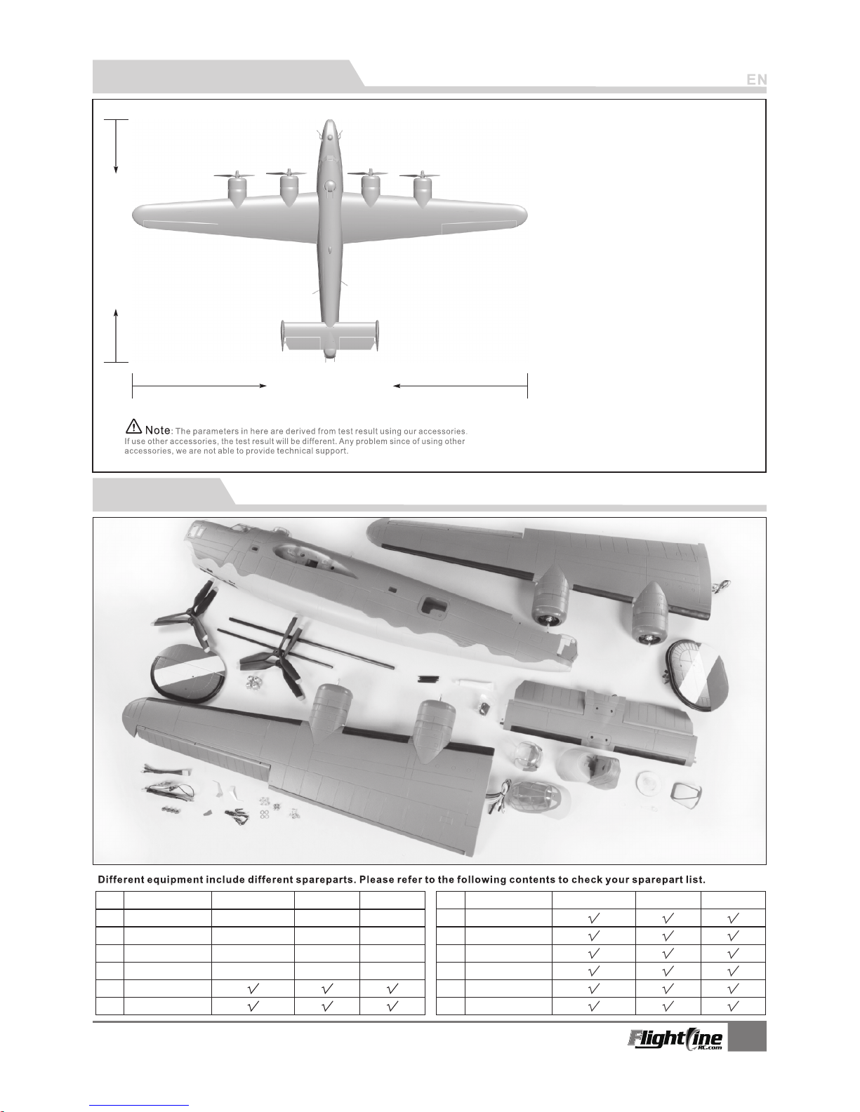
Product basic information
1230mm(4 8.4 in.)
Wing loa di ng 100g /d m²:
Wing :35dm ² area
Motor: 3 53 0-860KV
brushl es s ou tr unner motor (4p cs)
r -Bla de P opel le r : 3 9.5x 7
(4Pi ec s St andard/Re ve rs e)
ESC : 30 A(4p cs)
Servo : 9g d ig it al metal gear s er vo (9pcs)
Flight s pe ed 110KPH/70MP H:
Empty Weight : 291 0g(without ba tt er y)
5400 gPull :
Materi al:E PO
Ailero n: Yes
Flaps: Yes
Elevat or : Yes
Rudder : Yes
Landin g ge ar : Retractable , Su sp en sion
Scale Pi lo t fi gure
Batter y: 4 S 28 00-4000mAh (2 pc s)
2000mm(7 8.7 in.)
2
B-24 LIBERATO R
Ite n No.:
Package list
No. Name
No. Name
1
2
3
4
5
6
7
8
9
10
11
12
Glue & No n- slip ma t
Car bon tub e & Screw
Manual & Decals
PNP
ARF Pl us
Airf ra me
PNP
ARF Pl us
Airf ra me
Fuse la ge
Main w in g
Hori zo nt al tail
Verti ca l ta il
Pre -inst alled a ll
ele ctron ic part s
Pre -inst alled a ll
ele ctron ic part s
Pre -inst alled a ll
ele ctron ic part s
Pre -inst alled a ll
ele ctron ic part s
Pre -inst alled
ser vo
Pre -inst alled
ser vo
Pre -inst alled
ser vo
Pre -inst alled
ser vo
No el ectro nic
equ ipmen t
No el ectro nic
equ ipmen t
No el ectro nic
equ ipmen t
No el ectro nic
equ ipmen t
Prope ll er & Spin ne r
Nose Tur re t & Nose
Scale Ac ce ssori es
ESC wi re
Link ag e Se t
4
Step
2
Step
E
F
ABCDEF-
Rudd er
Elev ator
Serv o cable
Elev ator wi re chan nel
Scre w (PA3x 8 4p cs)
Scre w (PA3x 8 4p cs)
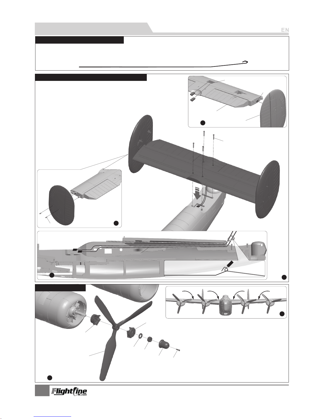
As shown in the photo below:
1.Fix the propeller on the motor.。
2.As the photo show, install the left/right propeller.
ABCDEFG-
Scre w (PM2.5x6 4 pc s)
Spin ner
Scre w nut
Was her
Prop eller f ixing b olt A
Scal e prope lle
Prop eller f ixing b olt B
3
B-24 LIBERATO R
Ite n No.:
1
Step
As sho wn in the p hoto be low:
1.In sert th e left/ right r udder s ervo ca ble int o the tro ugh of th e
hori zonta l tail, a nd pull t he cabl es from t he gap of h orizo ntal ta il.
2.Se cure th e left/ right v ertic al stab ilize r to the ho rizon tal tai l
with 4 pcs PA3x8 sc rews.
3.As t he phot o shows , bundl e the rud der/e levat or cabl es and us e the
Wire P ull-T hroug h Tool t o carry c ables t o the bat tery co mpart ment.
4.Fi nally, ins tall th e horiz ontal t ail on th e fusel age
and se cure it w ith 4pc s PA3 x8 scre ws.
A
B
C
D
Tra ction s teel wi re
Batt ery com partm ent
3
Step
Elev ator/ Rudde r servo c able
A
B
C
D
E
F
G
1
Step
2
Step
To minim ize ser vo conn ectio ns, the E levat or and Ru dder se rvos’ wires e ach rea ch from t he serv o itsel f direc tly to
the re ceive r. A rigid ste el wire h ook is in clude d in the bo x to allo w you to pu ll the se rvo wir es thro ugh the m odel’s
inte rnal fu selag e.
PNP lns tal lat ion Instructions
Wire P ull-T hroug h Tool In struc tions
Inst all Hor izont al Stab ilize r/Vert ical St abili zer
Inst all the P ropel ler
4
B-24 LIBERATO R
Ite n No.:
2
Step
3
Step
1
Step
Carb on tube A
(Ø10x500 mm )
C Barbo n tube
(Ø8x360m m)
3
3
1
6
5
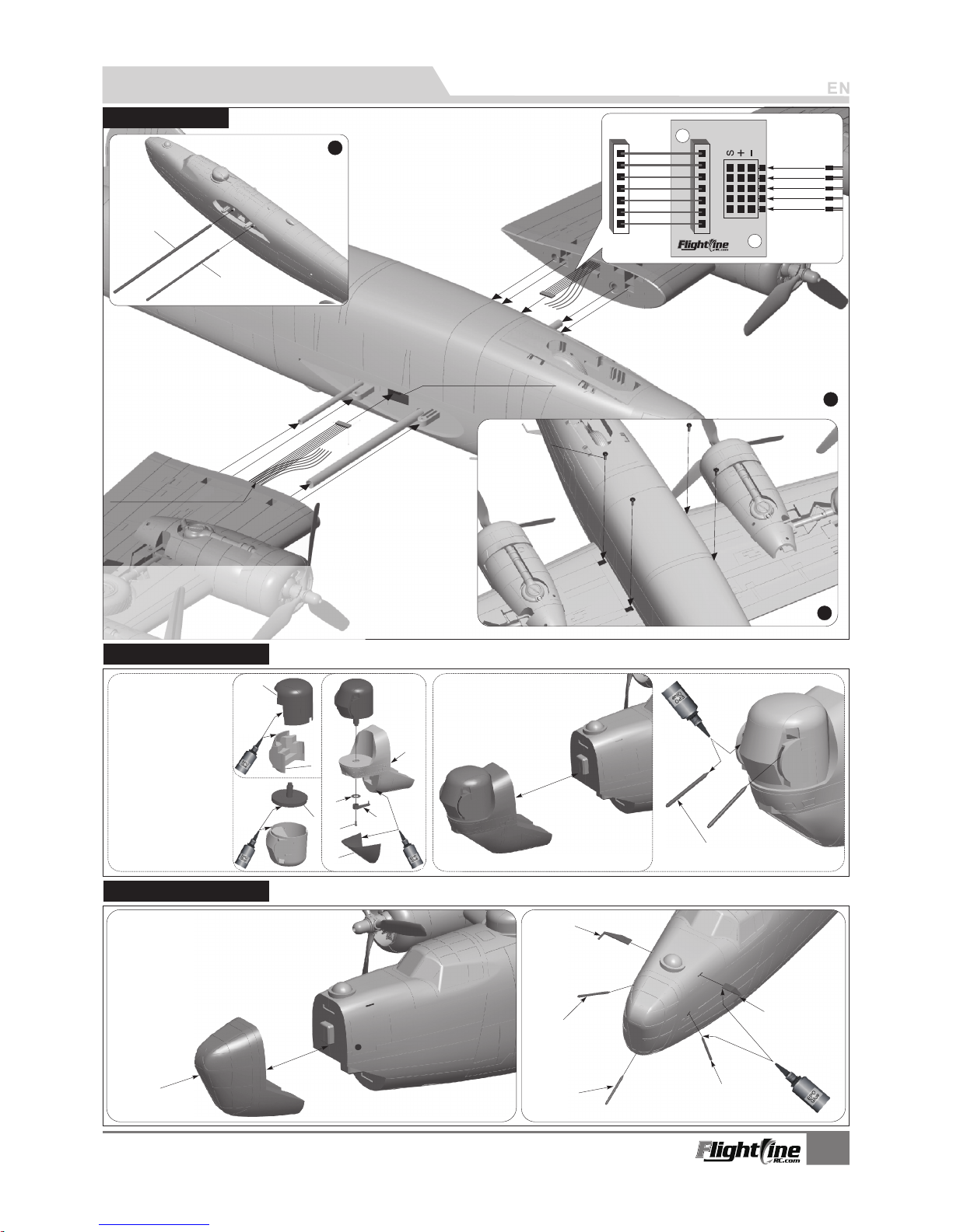
1.Insert carbon tube A and B into the fuselage.
2.Pull the ESC wire and Ribbo n wire through the hole.
3.Insert the left/right main wing on th e fusela ge .
4.Use 4pcs PWM4x8 screws to sec ur e the main wing.
Scre w
(PWM 4x 8 4p cs )
Main w ing wir e hole
A
B
C
C1
C2
B1
(PNP in cl ud es t wo o pt io na l fo rward nose sections for t he B -2 4- D (” Gr ee nh ou se ”) and B-24-J (”Emerson Tu rr et ”)
ABC-
Gree nhous e for -D Varia nt
Ante nnas
Gun Ba rrels
I
Mag
ne
t
A
B
C
D
E
F
G
H
PNP lns tal lat ion Instructions
Inst allMai n Wing
ESC wire & R ib bo n wire
Mag
n
e
t
Inst all Nos e Secti on -J
ABCD-
EF GHI -
Nose Turret A
Nose Turret B
Nose Turret Base
B-24-J
Variant Foam Nose
Washer
Tiller
Screw (PA2.3x8)
Lower Windshield
Gun Barrels
Inst all Nos e Secti on -D
Thr ottle
Thr ottle
Ail eron
Fla p
Lan ding ge ar
 Loading...